EP3780558B1 - Adressierung von slave-vorrichtungen mittels iterativer leistungsaktivierung - Google Patents
Adressierung von slave-vorrichtungen mittels iterativer leistungsaktivierung Download PDFInfo
- Publication number
- EP3780558B1 EP3780558B1 EP19306012.6A EP19306012A EP3780558B1 EP 3780558 B1 EP3780558 B1 EP 3780558B1 EP 19306012 A EP19306012 A EP 19306012A EP 3780558 B1 EP3780558 B1 EP 3780558B1
- Authority
- EP
- European Patent Office
- Prior art keywords
- index
- slave device
- slave
- master device
- power line
- Prior art date
- Legal status (The legal status is an assumption and is not a legal conclusion. Google has not performed a legal analysis and makes no representation as to the accuracy of the status listed.)
- Active
Links
Images


Classifications
-
- H—ELECTRICITY
- H04—ELECTRIC COMMUNICATION TECHNIQUE
- H04L—TRANSMISSION OF DIGITAL INFORMATION, e.g. TELEGRAPHIC COMMUNICATION
- H04L67/00—Network arrangements or protocols for supporting network services or applications
- H04L67/01—Protocols
- H04L67/12—Protocols specially adapted for proprietary or special-purpose networking environments, e.g. medical networks, sensor networks, networks in vehicles or remote metering networks
-
- G—PHYSICS
- G06—COMPUTING OR CALCULATING; COUNTING
- G06F—ELECTRIC DIGITAL DATA PROCESSING
- G06F13/00—Interconnection of, or transfer of information or other signals between, memories, input/output devices or central processing units
- G06F13/14—Handling requests for interconnection or transfer
- G06F13/36—Handling requests for interconnection or transfer for access to common bus or bus system
- G06F13/362—Handling requests for interconnection or transfer for access to common bus or bus system with centralised access control
-
- G—PHYSICS
- G06—COMPUTING OR CALCULATING; COUNTING
- G06F—ELECTRIC DIGITAL DATA PROCESSING
- G06F11/00—Error detection; Error correction; Monitoring
- G06F11/07—Responding to the occurrence of a fault, e.g. fault tolerance
- G06F11/0703—Error or fault processing not based on redundancy, i.e. by taking additional measures to deal with the error or fault not making use of redundancy in operation, in hardware, or in data representation
- G06F11/0766—Error or fault reporting or storing
- G06F11/0772—Means for error signaling, e.g. using interrupts, exception flags, dedicated error registers
-
- G—PHYSICS
- G06—COMPUTING OR CALCULATING; COUNTING
- G06F—ELECTRIC DIGITAL DATA PROCESSING
- G06F11/00—Error detection; Error correction; Monitoring
- G06F11/30—Monitoring
- G06F11/3058—Monitoring arrangements for monitoring environmental properties or parameters of the computing system or of the computing system component, e.g. monitoring of power, currents, temperature, humidity, position, vibrations
-
- G—PHYSICS
- G06—COMPUTING OR CALCULATING; COUNTING
- G06F—ELECTRIC DIGITAL DATA PROCESSING
- G06F13/00—Interconnection of, or transfer of information or other signals between, memories, input/output devices or central processing units
- G06F13/14—Handling requests for interconnection or transfer
- G06F13/36—Handling requests for interconnection or transfer for access to common bus or bus system
- G06F13/368—Handling requests for interconnection or transfer for access to common bus or bus system with decentralised access control
- G06F13/37—Handling requests for interconnection or transfer for access to common bus or bus system with decentralised access control using a physical-position-dependent priority, e.g. daisy chain, round robin or token passing
-
- H—ELECTRICITY
- H04—ELECTRIC COMMUNICATION TECHNIQUE
- H04L—TRANSMISSION OF DIGITAL INFORMATION, e.g. TELEGRAPHIC COMMUNICATION
- H04L61/00—Network arrangements, protocols or services for addressing or naming
- H04L61/50—Address allocation
-
- H—ELECTRICITY
- H04—ELECTRIC COMMUNICATION TECHNIQUE
- H04L—TRANSMISSION OF DIGITAL INFORMATION, e.g. TELEGRAPHIC COMMUNICATION
- H04L61/00—Network arrangements, protocols or services for addressing or naming
- H04L61/50—Address allocation
- H04L61/5038—Address allocation for local use, e.g. in LAN or USB networks, or in a controller area network [CAN]
Definitions
- the present invention relates to network systems comprising serial bus slave devices controlled by a master device.
- it concerns allocation of addresses to the slave devices during a configuration phase, such as during start-up of the network system for example.
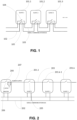
- slave devices 101.1, 101.2 and 101.3 of a network system there are shown slave devices 101.1, 101.2 and 101.3 of a network system according to the prior art.
- the slave devices 101 are connected via a communication bus comprising two communication lines 102 and 103. Each slave device 101 also comprises respective switches 104 and 105 to disconnect the next slave device from each of the communications lines 102 and 103.
- the bus switching mechanism is implemented on the communication bus itself.
- US 5,814,771 A , US 2018/219582 A1 and EP 3 454 532 A1 also disclose slave devices connected to form Daisy chains and methods for assigning unique addresses to each slave device.
- a first aspect of the invention concerns a method for addressing a slave device in a network system comprising a master device and a plurality of slave devices, as stated in claim 1.
- Such an iterative process allows addressing one unaddressed slave device at a time, which allows efficiently detecting and activating the slave devices. Indeed, at each iteration, there is only one unaddressed slave device in the network. It also makes it easy to detect a faulty slave device.
- the method comprises measuring a value of a current consumption on the power line, and, based on a comparison between the measured value and a previous value, determining whether the slave device of index k is correctly activated or not.
- the detection of a fault is performed efficiently and at a lower cost, as it only requires measuring the current drawn on the power line at each iteration.
- the command to change the common default address of the slave device of index k may be sent if the difference between the measured value and the previous value is substantially different from zero.
- the command to change the common default address of the slave device of index k may be sent if the difference between the measured value and the previous value is within a predetermined range, else the master device issues an error message.
- the method may comprise the following operations:
- the command to change the common default address of the slave device of index k may be sent if an acknowledgment has been received from the slave device of index k-1 following the instruction sent on the communication line.
- the method may further comprise sending a presence query to the unique address of index k, and, upon receiving of an acknowledgment to the presence query from the slave device of index k, repeating the operations of the method for the slave device of index k+1.
- the unique address of index k may be a code determined based on index k.
- a second aspect of the invention concerns a non-transitory computer readable storage medium, with a computer program stored thereon, the computer program comprising instructions for, when executed by a processor, carrying out the steps of a method according to the first aspect of the invention.
- a third aspect of the invention a master device for addressing a slave device in a network system comprising the master device and a plurality of slave devices, wherein the slave devices have a common default address in an unaddressed state, the master device comprising:
- a fourth aspect of the invention concerns a system comprising a master device according to the third aspect and a plurality of slave devices connected in chain to the master device.
- FIG. 2 there is shown a network system according to some embodiments of the invention.
- the network system comprises a master device 200 and a plurality of N slave devices 201.1, 201.k-1, 201.k, ... 201.N, N being an integer greater than or equal to 2, and k being an index varying between 1 and N.
- the slave devices 201 are thereby forming a " Daisy " chain.
- the master device 200 is connected to the chain of slave devices 201 via a communication line 202 and a power line 203.
- the communication line 202 may comprise several unidirectional lines as shown on Figure 2 , or alternatively only one bidirectional line.
- the master device may comprise an activation circuit 206 and a sensing circuit 207.
- the activation circuit 206 is configured for activating/deactivating the power line 203.
- the activation circuit 206 may be a switch placed between a power source (not represented on Figure 1 ) and the slave devices 201.
- Each slave device 201.k of index k also comprises a circuit 205 for connecting/disconnecting a slave device of index k+1 (the next one in the Daisy chain).
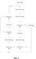
- Figure 3 is a diagram showing the steps of a method according to some embodiments of the invention.
- all the slave devices have a common default address, such as 0*FE for example.
- the master device 200 activates the power line 203 using the activation circuit 206.
- the circuit 206 may comprise a switch between the power source and the slave devices 201.
- N represents the number of slave devices 201 in the network system. N is not known in advance by the master device 200 and is only determined once the method according to the invention is terminated.
- the master device 200 optionally measures the power consumed on the power line 203.
- the master device 200 measures the current drawn on the power line 203.
- the current drawn on the power line 203 may then be stored in a memory of the master device 200. This measure can be subsequently used to detect a fault in a slave device, according to optional embodiments.
- the master device 200 sends an instruction, via the communication line 202, to the slave device of index k-1 to enable the power line 203 of the slave device of index k, via the communication line 202.
- the master device 200 activates its activation circuit 206 to activate the slave device 201.1 without the need to send any instruction.
- the master device 200 optionally waits until the measures performed by the sensing unit are stabilized. Indeed, once the slave device k-1 is connected to the power line 203, it increases the current drawn on the power line 203 and the current may be stabilized after a certain amount of time.
- the master device 200 measures the power drawn on the power line 203, such as for example the current drawn on the power line 203.
- the master device 200 compares the measurement performed at step 306 with the measurement performed at step 301 or alternatively with the measurement performed at step 306 for the previous iteration k-1.
- the master device 200 checks whether the measurements at iterations k and k-1 are substantially the same (their difference is substantially equal to 0). If so, then the method can be terminated at step 305: it is concluded that there is no slave device of index k and that N is equal to k-1. Else, the method goes to step 308.
- the master devices 200 checks whether the difference between the compared measurements is below a predetermined threshold.
- the threshold is representative of a current that can be normally drawn by a slave device. If not (if the difference is above the predetermined threshold), then the method terminates at step 305: it is concluded that the slave device 201.k is faulty. An error message/alarm can be issued at step 305.
- the master device 200 sends a command to change the common default address of the slave device of index k to a unique address of index k, via the communication line 202.
- the command is intended to the common default address, as the slave device of index k is the only slave device that is active and that has the common default address (the other slave devices have been previously addressed with unique addresses), such as 0*FE.
- the common default address can be put in a recipient field of the command (depending on the communication protocol used on the communication line 202).
- the unique address can have the same format as the common default address (a digit and two letters for example) and may code the index k of the slave device 201.k.
- the address of the first slave device of index 1 can be 0*AA or 0*01 for example.
- the unique address of index k can be included in a payload of the command.
- the master device optionally checks whether a response to the command is received from slave device 201.k. If not, the method terminates at step 305: it is concluded that the unique address of index k has not been correctly assigned.
- the method is iterated with next index k+1 and goes back to step 301.
- a query can be sent to the unique address of index k, to check whether the slave device 201.k is properly configured.
- step 312 If a response is received at step 312, the method is iterated with next index k+1 and goes back to step 301.
- step 312 If no response is received at step 312, the method terminates at step 305: it is concluded that slave device 201.k is not enrolled.
- the method provides the advantage to easily measure the current consumption of the devices in the Daisy chain, allowing the master device 200 to determine whether a slave device 201 is behaving within its operating conditions. It can also differentiate between a slave device being absent, operating faulty or normally.
- Figure 4 shows a structure of a master device 200 according to some embodiments of the invention.
- the master device 200 comprises a memory 401 such as a Read Only Memory, ROM, a Random-Access Memory, RAM, a flash memory or any other type of memory, and a processor 400 that is configured for performing the steps illustrated on Figure 3 .
- the processor 400 may be replaced by an electronic circuit such as a microcontroller that is configured for performing the steps illustrated on Figure 3 .
- the master device 200 may further comprise a communication interface 402 for communicating via the communication line 202 and a power interface 403 between the activation circuit 206 and the slave devices 201.
- the master device 200 further comprises a sensing circuit 207 configured for measuring the power drawn on the power line 203.
- FIG. 5 there is shown a structure of the circuit 205 of a slave device 201. This structure is given for illustrative purposes only.
- the structure of the circuit 205 comprises:
- a signal UC_OK is received from the master device 200 to enable/disable the next slave device.
- FIG. 6 there is shown a structure of the sensing circuit 207 according to some embodiments of the invention. This structure is given for illustrative purposes only.
- the circuit of the sensing circuit 207 comprises:
- a sensed current signal I_SENSE is sent to the processor 400 of the master device 200.
Landscapes
- Engineering & Computer Science (AREA)
- Theoretical Computer Science (AREA)
- General Engineering & Computer Science (AREA)
- General Physics & Mathematics (AREA)
- Physics & Mathematics (AREA)
- Computer Networks & Wireless Communication (AREA)
- Signal Processing (AREA)
- Quality & Reliability (AREA)
- Computing Systems (AREA)
- Health & Medical Sciences (AREA)
- Medical Informatics (AREA)
- General Health & Medical Sciences (AREA)
- Small-Scale Networks (AREA)
Claims (9)
- Verfahren zum Adressieren einer Slave-Vorrichtung in einem Netzwerksystem, welches eine Master-Vorrichtung (200) und eine Mehrzahl von Slave-Vorrichtungen (201.1-201.k) umfasst, wobei die Slave-Vorrichtungen in einem nicht-adressierten Zustand eine gemeinsame Standardadresse aufweisen und wobei die Master-Vorrichtung und die Mehrzahl von Slave-Vorrichtungen über eine Stromversorgungsleitung (203) und eine Kommunikationsleitung (202) in einer Daisy-Chain verbunden sind,wobei jede Slave-Vorrichtung durch einen Index indexiert ist, welcher größer oder gleich 1 ist, wobei die Slave-Vorrichtung (201.1) mit Index 1 mit der Master-Vorrichtung (200) verbunden ist und die Slave-Vorrichtung mit Index k+1 in der Daisy-Chain die Nächste nach der Slave-Vorrichtung (201.k) mit Index k ist,wobei jede Slave-Vorrichtung (201 .k) mit Index k einen Schalter (205) zum Verbinden/Trennen der Slave-Vorrichtung mit Index k+1 umfasst,wobei in einem Schritt 300 die Master-Vorrichtung (200) unter Verwendung einer Aktivierungsschaltung (206) der Master-Vorrichtung die Stromversorgungsleitung (203) aktiviert,wobei, um die Slave-Vorrichtung (201.k) mit Index k zu adressieren, wobei k gleich wie oder größer als 2 ist, das Verfahren die folgenden Vorgänge einer Iteration k umfasst, welche durch die Master-Vorrichtung (200) durchgeführt werden, um den Index k zu erhöhen:- optionaler Schritt 301: Messen des auf der Stromversorgungsleitung (203) gezogenen Stroms;- Schritt 302: Anweisen, über die Kommunikationsleitung (202), der Slave-Vorrichtung (201.k-1) mit Index k-1, über die Stromversorgungsleitung (203) die Stromversorgung der Slave-Vorrichtung (201.k) mit Index k zu aktivieren;- Schritt 306: Messen eines Werts eines Stromverbrauchs auf der Stromversorgungsleitung (203);- Schritt 307: Bestimmen einer Differenz zwischen dem in Schritt 306 mit Iteration k gemessenen Wert und eines in Schritt 301 mit k oder in Schritt 306 mit Iteration k-1 gemessenen vorherigen Werts und Beenden des Verfahrens, wenn die Differenz im Wesentlichen gleich Null ist, da geschlussfolgert wird, dass es keine Slave-Vorrichtung mit Index k gibt;- Schritt 308: Prüfen, ob die Differenz unterhalb eines vorbestimmten Schwellenwerts liegt, und falls nicht, Beenden des Verfahrens, da geschlussfolgert wird, dass die Slave-Vorrichtung mit Index k fehlerhaft ist; und- Schritt 309: Senden, auf der Kommunikationsleitung an die gemeinsame Standardadresse, eines Befehls, die gemeinsame Standardadresse der Slave-Vorrichtung (201.k) mit Index k in eine eindeutige Adresse mit Index k zu ändern.
- Verfahren nach Anspruch 1, wobei, wenn die Differenz zwischen dem in Schritt 306 gemessenen Wert und dem vorherigen Wert nicht innerhalb eines vorbestimmten Bereichs liegt, die Master-Vorrichtung (200) eine Fehlermeldung ausgibt.
- Verfahren nach Anspruch 1 oder 2, wobei, für die Slave-Vorrichtung (201.1) mit Index 1, das Verfahren die folgenden Vorgänge umfasst:- Messen (301) des Stromverbrauchs auf der Stromversorgungsleitung (203) und Speichern des Stromverbrauchs als den vorherigen Wert;- Aktivieren (302) der Slave-Vorrichtung (201.1) mit Index 1 über die Stromversorgungsleitung (203); und- Messen (306) des Stromverbrauchs auf der Stromversorgungsleitung, nachdem die Slave-Vorrichtung (201.1) mit Index 1 aktiviert worden ist.
- Verfahren nach einem der Ansprüche 1-2, wobei der Befehl, die gemeinsame Standardadresse der Slave-Vorrichtung (201.k) mit Index k zu ändern, gesendet wird, wenn, auf die auf der Kommunikationsleitung (202) gesendete Anweisung folgend, eine Bestätigung von der Slave-Vorrichtung (201.k-1) mit Index k-1 empfangen worden ist.
- Verfahren nach einem der Ansprüche 1-2, ferner umfassend ein Senden (311) einer Anwesenheitsabfrage an die eindeutige Adresse mit Index k und, auf ein Empfangen (312) einer Bestätigung für die Anwesenheitsabfrage von der Slave-Vorrichtung (200.k) mit Index k hin, ein Wiederholen der Vorgänge des Verfahrens für die Slave-Vorrichtung (200.k+1) mit Index k+1.
- Verfahren nach einem der Ansprüche 1-2, wobei die eindeutige Adresse mit Index k ein basierend auf Index k bestimmter Code ist.
- Nicht-transitorisches computerlesbares Speichermedium mit einem darauf gespeicherten Computerprogramm, wobei das Computerprogramm Anweisungen zum Durchführen, wenn es durch einen Prozessor ausgeführt wird, der Schritte eines Verfahrens nach einem der Ansprüche 1 bis 6 umfasst.
- Master-Vorrichtung (200) zum Adressieren einer Slave-Vorrichtung in einem Netzwerksystem, welches die Master-Vorrichtung und eine Mehrzahl von Slave-Vorrichtungen (201.1-201.k) umfasst, wobei die Slave-Vorrichtungen in einem nicht-adressierten Zustand eine gemeinsame Standardadresse aufweisen, wobei die Master-Vorrichtung umfasst:eine erste Schnittstelle (403), um auf eine Stromversorgungsleitung (203) zur Stromversorgung der Slave-Vorrichtungen (201.1-201.k) zuzugreifen;eine zweite Schnittstelle (402) zum Kommunizieren mit den Slave-Vorrichtungen (201.1-201.k) über eine Kommunikationsleitung (202);wobei jede Slave-Vorrichtung (201.1-201.k) durch einen Index indexiert ist, welcher größer oder gleich 1 ist, wobei die Master-Vorrichtung (200) mit der Slave-Vorrichtung (200.1) mit Index 1 verbunden ist,wobei die Master-Vorrichtung (200) einen Prozessor (400) umfasst, welcher das Verfahren nach Anspruch 1 implementiert.
- System, umfassend eine Master-Vorrichtung nach Anspruch 8 und eine Mehrzahl von Slave-Vorrichtungen (201.1-201.k), welche verkettet mit der Master-Vorrichtung (200) verbunden sind.
Priority Applications (4)
| Application Number | Priority Date | Filing Date | Title |
|---|---|---|---|
| EP19306012.6A EP3780558B1 (de) | 2019-08-14 | 2019-08-14 | Adressierung von slave-vorrichtungen mittels iterativer leistungsaktivierung |
| US16/942,056 US11232055B2 (en) | 2019-08-14 | 2020-07-29 | Addressing of slave devices using interative power activation |
| CN202010799889.XA CN112398961B (zh) | 2019-08-14 | 2020-08-11 | 使用迭代电力激活对从设备寻址 |
| JP2020136798A JP7521967B2 (ja) | 2019-08-14 | 2020-08-13 | 反復型電源起動を使用したスレーブ・デバイスのアドレス指定 |
Applications Claiming Priority (1)
| Application Number | Priority Date | Filing Date | Title |
|---|---|---|---|
| EP19306012.6A EP3780558B1 (de) | 2019-08-14 | 2019-08-14 | Adressierung von slave-vorrichtungen mittels iterativer leistungsaktivierung |
Publications (2)
| Publication Number | Publication Date |
|---|---|
| EP3780558A1 EP3780558A1 (de) | 2021-02-17 |
| EP3780558B1 true EP3780558B1 (de) | 2025-02-19 |
Family
ID=67981998
Family Applications (1)
| Application Number | Title | Priority Date | Filing Date |
|---|---|---|---|
| EP19306012.6A Active EP3780558B1 (de) | 2019-08-14 | 2019-08-14 | Adressierung von slave-vorrichtungen mittels iterativer leistungsaktivierung |
Country Status (4)
| Country | Link |
|---|---|
| US (1) | US11232055B2 (de) |
| EP (1) | EP3780558B1 (de) |
| JP (1) | JP7521967B2 (de) |
| CN (1) | CN112398961B (de) |
Families Citing this family (3)
| Publication number | Priority date | Publication date | Assignee | Title |
|---|---|---|---|---|
| JP2021150732A (ja) * | 2020-03-17 | 2021-09-27 | キヤノン株式会社 | マスタスレーブ通信システム、電子デバイス、マスタスレーブ通信システムの制御方法、電子デバイスの制御方法 |
| EP4175238B1 (de) * | 2021-10-27 | 2026-02-18 | Schneider Electric Industries SAS | Konfiguration von slave-vorrichtungen in einem industriellen netzwerksystem |
| CN114035524B (zh) * | 2021-11-11 | 2025-01-21 | 成都卡诺普机器人技术股份有限公司 | 控制方法和自动控制系统 |
Family Cites Families (32)
| Publication number | Priority date | Publication date | Assignee | Title |
|---|---|---|---|---|
| CA1338639C (en) * | 1989-09-26 | 1996-10-08 | Seiichi Kubo | Communication control device |
| JPH0818597A (ja) * | 1994-07-01 | 1996-01-19 | Yamatake Honeywell Co Ltd | アドレス設定方法および装置 |
| US5814771A (en) * | 1996-02-16 | 1998-09-29 | Structural Instrumentation, Inc. | On-board microprocessor controlled load weighing system |
| DE19647668A1 (de) * | 1996-11-19 | 1998-05-28 | Bosch Gmbh Robert | Slavestation, Masterstation, BUS-System und Verfahren zum Betreiben eines BUS-Systems |
| JP3565200B2 (ja) * | 2001-11-08 | 2004-09-15 | 株式会社デンソー | 車両用障害物検知装置 |
| US20030065730A1 (en) * | 2001-09-28 | 2003-04-03 | Jones Kevin M. | Method for determining a primary communication module |
| DE10215720A1 (de) | 2002-04-10 | 2003-10-30 | Philips Intellectual Property | Datenbus-Netzwerk |
| EP1627831B1 (de) * | 2004-08-17 | 2007-10-10 | Dematic S.r.l. | Sortier- und Verteilsystem sowie ein Verfahren zur Energie- und Datenübertragung |
| US7532956B1 (en) * | 2004-08-24 | 2009-05-12 | Pelaez Jr Pedro | Distributed power and protection system |
| JP2006165957A (ja) | 2004-12-07 | 2006-06-22 | Victor Co Of Japan Ltd | シリアル通信システム及びアドレス設定方法 |
| US7518894B2 (en) * | 2005-03-31 | 2009-04-14 | Silicon Laboratories Inc. | Distributed power supply system having reassignable master |
| US7631110B2 (en) * | 2006-05-03 | 2009-12-08 | Standard Microsystems Corporation | Address assignment through device ID broadcast |
| US8433874B2 (en) * | 2006-12-06 | 2013-04-30 | Mosaid Technologies Incorporated | Address assignment and type recognition of serially interconnected memory devices of mixed type |
| US8122159B2 (en) * | 2009-01-16 | 2012-02-21 | Allegro Microsystems, Inc. | Determining addresses of electrical components arranged in a daisy chain |
| US8296488B2 (en) | 2009-04-27 | 2012-10-23 | Abl Ip Holding Llc | Automatic self-addressing method for wired network nodes |
| EP2425238B1 (de) * | 2009-05-01 | 2018-10-17 | Analog Devices, Inc. | Ansteuerbarer integrierter schaltkreis und verfahren dafür |
| US9184987B2 (en) * | 2011-02-23 | 2015-11-10 | Tyco Fire & Security Gmbh | System and method for automatic configuration of master/slave devices on a network |
| US9003096B2 (en) * | 2011-03-16 | 2015-04-07 | Texas Instruments Incorporated | Serial interface |
| JP5457480B2 (ja) * | 2012-02-14 | 2014-04-02 | アンリツ株式会社 | 移動体通信用試験装置及び試験方法 |
| GB201214859D0 (en) * | 2012-08-20 | 2012-10-03 | Control Tech Ltd | Node address allocation |
| JP5987758B2 (ja) * | 2013-04-04 | 2016-09-07 | 株式会社デンソー | プログラム及び制御装置 |
| US9519278B2 (en) * | 2014-06-09 | 2016-12-13 | Richard J. Petrocy | Modularized self-addressing apparatus and method |
| DE102015113491A1 (de) * | 2015-08-14 | 2017-02-16 | Ebm-Papst Mulfingen Gmbh & Co. Kg | Dynamikadressierung |
| FR3040845B1 (fr) | 2015-09-04 | 2018-05-18 | Schneider Electric Industries Sas | Methode d'adressage automatique dans une architecture de communication ethernet |
| US9990316B2 (en) * | 2015-09-21 | 2018-06-05 | Qualcomm Incorporated | Enhanced serial peripheral interface |
| DE102016214416A1 (de) * | 2016-08-04 | 2018-02-08 | Continental Automotive Gmbh | Verfahren zur Vergabe von Adressen durch eine Master-Einheit an eine Anzahl von Slave-Einheiten |
| US10715350B2 (en) * | 2016-09-19 | 2020-07-14 | Simmonds Precision Products, Inc. | Automatic addressing of networked nodes |
| US10120829B2 (en) * | 2016-11-23 | 2018-11-06 | Infineon Technologies Austria Ag | Bus device with programmable address |
| US10122412B2 (en) * | 2017-01-30 | 2018-11-06 | Abl Ip Holding, Llc | Power line communication system and method of auto-commissioning system nodes |
| US10725949B2 (en) * | 2018-08-28 | 2020-07-28 | Qualcomm Incorporated | Slave-to-slave direct communication |
| US20200125520A1 (en) * | 2018-10-23 | 2020-04-23 | Astronics Advanced Electronic Systems Corp. | Methods and Systems for Assigning Addresses to Devices That Use Master / Slave Communication Protocols |
| CA3121568A1 (en) * | 2018-11-29 | 2020-06-04 | Grote Industries, Inc. | Smart cable system for a truck trailer |
-
2019
- 2019-08-14 EP EP19306012.6A patent/EP3780558B1/de active Active
-
2020
- 2020-07-29 US US16/942,056 patent/US11232055B2/en active Active
- 2020-08-11 CN CN202010799889.XA patent/CN112398961B/zh active Active
- 2020-08-13 JP JP2020136798A patent/JP7521967B2/ja active Active
Also Published As
| Publication number | Publication date |
|---|---|
| EP3780558A1 (de) | 2021-02-17 |
| JP7521967B2 (ja) | 2024-07-24 |
| CN112398961A (zh) | 2021-02-23 |
| CN112398961B (zh) | 2024-09-20 |
| US11232055B2 (en) | 2022-01-25 |
| JP2021044798A (ja) | 2021-03-18 |
| US20210049121A1 (en) | 2021-02-18 |
Similar Documents
| Publication | Publication Date | Title |
|---|---|---|
| US11232055B2 (en) | Addressing of slave devices using interative power activation | |
| CN110851392B (zh) | 基于Modbus RTU协议的通讯方法及通讯系统 | |
| WO2016081759A1 (en) | DETECTING GROUND ISOLATION FAULT IN ETHERNET PoDL SYSTEM | |
| CN109445375B (zh) | Plc冗余系统和plc冗余方法 | |
| US20180210854A1 (en) | Bus system | |
| CN107959599A (zh) | 一种Bus_Off故障测试系统及测试方法 | |
| CN110287135B (zh) | 一种总线轮询方法和装置 | |
| US20140143588A1 (en) | Instant Communication Error Indication From Slave | |
| CN104796306A (zh) | 一种端口模式协商方法和设备 | |
| CN109217922B (zh) | 一种光模块上报接收信号丢失告警的方法及装置 | |
| WO2018125761A1 (en) | Method and apparatus for automatic detection and selection of power over ethernet and power over powered data lines | |
| JP2005277978A (ja) | 識別番号自動設定方法及び識別番号自動設定装置 | |
| CN102147783B (zh) | 主从设备通信电路 | |
| CN115913884A (zh) | 通信方法、EtherCAT系统、通信装置及存储介质 | |
| US9425994B2 (en) | Discovering devices in a network | |
| CN112118163B (zh) | 在自动化系统中进行能量传输和数据传输的系统和方法 | |
| CN207652457U (zh) | 一种Bus_Off故障测试系统 | |
| CN111382018A (zh) | 串行通信的故障检测方法及装置、可读存储介质 | |
| US20220021555A1 (en) | Decentralised communication system and corresponding control method | |
| US20250126012A1 (en) | Network node for a multidrop single pair ethernet and corresponding method | |
| CN104202443A (zh) | 对ip地址冲突进行容灾处理的方法和装置、以及相应设备 | |
| US20030021390A1 (en) | Device for connection of a device on a telephone line | |
| WO2026081659A1 (en) | Management method and apparatus for ethernet protocol categories of apl device, and load cell | |
| CN101677288B (zh) | 因特网的远程通讯方法及其系统 | |
| CN119544669A (zh) | 一种基于电阻压降来自动分配从机地址的方法 |
Legal Events
| Date | Code | Title | Description |
|---|---|---|---|
| PUAI | Public reference made under article 153(3) epc to a published international application that has entered the european phase |
Free format text: ORIGINAL CODE: 0009012 |
|
| STAA | Information on the status of an ep patent application or granted ep patent |
Free format text: STATUS: THE APPLICATION HAS BEEN PUBLISHED |
|
| AK | Designated contracting states |
Kind code of ref document: A1 Designated state(s): AL AT BE BG CH CY CZ DE DK EE ES FI FR GB GR HR HU IE IS IT LI LT LU LV MC MK MT NL NO PL PT RO RS SE SI SK SM TR |
|
| AX | Request for extension of the european patent |
Extension state: BA ME |
|
| STAA | Information on the status of an ep patent application or granted ep patent |
Free format text: STATUS: REQUEST FOR EXAMINATION WAS MADE |
|
| 17P | Request for examination filed |
Effective date: 20210810 |
|
| RBV | Designated contracting states (corrected) |
Designated state(s): AL AT BE BG CH CY CZ DE DK EE ES FI FR GB GR HR HU IE IS IT LI LT LU LV MC MK MT NL NO PL PT RO RS SE SI SK SM TR |
|
| STAA | Information on the status of an ep patent application or granted ep patent |
Free format text: STATUS: EXAMINATION IS IN PROGRESS |
|
| 17Q | First examination report despatched |
Effective date: 20221208 |
|
| REG | Reference to a national code |
Ref country code: DE Free format text: PREVIOUS MAIN CLASS: H04L0029120000 Ref legal event code: R079 Ref document number: 602019066106 Country of ref document: DE Ipc: H04L0061503800 |
|
| GRAP | Despatch of communication of intention to grant a patent |
Free format text: ORIGINAL CODE: EPIDOSNIGR1 |
|
| STAA | Information on the status of an ep patent application or granted ep patent |
Free format text: STATUS: GRANT OF PATENT IS INTENDED |
|
| INTG | Intention to grant announced |
Effective date: 20240924 |
|
| RIC1 | Information provided on ipc code assigned before grant |
Ipc: H04L 67/12 20220101ALI20240913BHEP Ipc: H04L 61/5038 20220101AFI20240913BHEP |
|
| RIN1 | Information on inventor provided before grant (corrected) |
Inventor name: PLESSIS, BENJAMIN Inventor name: CASERAS, LOIC Inventor name: MOLINA, GREGORY Inventor name: GARCIA VIANO, PABLO Inventor name: CASTILLO BUENAVENTURA, FELIPE |
|
| GRAS | Grant fee paid |
Free format text: ORIGINAL CODE: EPIDOSNIGR3 |
|
| GRAA | (expected) grant |
Free format text: ORIGINAL CODE: 0009210 |
|
| STAA | Information on the status of an ep patent application or granted ep patent |
Free format text: STATUS: THE PATENT HAS BEEN GRANTED |
|
| AK | Designated contracting states |
Kind code of ref document: B1 Designated state(s): AL AT BE BG CH CY CZ DE DK EE ES FI FR GB GR HR HU IE IS IT LI LT LU LV MC MK MT NL NO PL PT RO RS SE SI SK SM TR |
|
| REG | Reference to a national code |
Ref country code: GB Ref legal event code: FG4D |
|
| REG | Reference to a national code |
Ref country code: CH Ref legal event code: EP |
|
| REG | Reference to a national code |
Ref country code: DE Ref legal event code: R096 Ref document number: 602019066106 Country of ref document: DE |
|
| REG | Reference to a national code |
Ref country code: IE Ref legal event code: FG4D |
|
| REG | Reference to a national code |
Ref country code: NL Ref legal event code: MP Effective date: 20250219 |
|
| PG25 | Lapsed in a contracting state [announced via postgrant information from national office to epo] |
Ref country code: RS Free format text: LAPSE BECAUSE OF FAILURE TO SUBMIT A TRANSLATION OF THE DESCRIPTION OR TO PAY THE FEE WITHIN THE PRESCRIBED TIME-LIMIT Effective date: 20250519 |
|
| PG25 | Lapsed in a contracting state [announced via postgrant information from national office to epo] |
Ref country code: FI Free format text: LAPSE BECAUSE OF FAILURE TO SUBMIT A TRANSLATION OF THE DESCRIPTION OR TO PAY THE FEE WITHIN THE PRESCRIBED TIME-LIMIT Effective date: 20250219 |
|
| PG25 | Lapsed in a contracting state [announced via postgrant information from national office to epo] |
Ref country code: PL Free format text: LAPSE BECAUSE OF FAILURE TO SUBMIT A TRANSLATION OF THE DESCRIPTION OR TO PAY THE FEE WITHIN THE PRESCRIBED TIME-LIMIT Effective date: 20250219 |
|
| PG25 | Lapsed in a contracting state [announced via postgrant information from national office to epo] |
Ref country code: ES Free format text: LAPSE BECAUSE OF FAILURE TO SUBMIT A TRANSLATION OF THE DESCRIPTION OR TO PAY THE FEE WITHIN THE PRESCRIBED TIME-LIMIT Effective date: 20250219 |
|
| REG | Reference to a national code |
Ref country code: LT Ref legal event code: MG9D |
|
| PG25 | Lapsed in a contracting state [announced via postgrant information from national office to epo] |
Ref country code: NO Free format text: LAPSE BECAUSE OF FAILURE TO SUBMIT A TRANSLATION OF THE DESCRIPTION OR TO PAY THE FEE WITHIN THE PRESCRIBED TIME-LIMIT Effective date: 20250519 Ref country code: IS Free format text: LAPSE BECAUSE OF FAILURE TO SUBMIT A TRANSLATION OF THE DESCRIPTION OR TO PAY THE FEE WITHIN THE PRESCRIBED TIME-LIMIT Effective date: 20250619 |
|
| PG25 | Lapsed in a contracting state [announced via postgrant information from national office to epo] |
Ref country code: NL Free format text: LAPSE BECAUSE OF FAILURE TO SUBMIT A TRANSLATION OF THE DESCRIPTION OR TO PAY THE FEE WITHIN THE PRESCRIBED TIME-LIMIT Effective date: 20250219 |
|
| PG25 | Lapsed in a contracting state [announced via postgrant information from national office to epo] |
Ref country code: HR Free format text: LAPSE BECAUSE OF FAILURE TO SUBMIT A TRANSLATION OF THE DESCRIPTION OR TO PAY THE FEE WITHIN THE PRESCRIBED TIME-LIMIT Effective date: 20250219 |
|
| PG25 | Lapsed in a contracting state [announced via postgrant information from national office to epo] |
Ref country code: LV Free format text: LAPSE BECAUSE OF FAILURE TO SUBMIT A TRANSLATION OF THE DESCRIPTION OR TO PAY THE FEE WITHIN THE PRESCRIBED TIME-LIMIT Effective date: 20250219 Ref country code: PT Free format text: LAPSE BECAUSE OF FAILURE TO SUBMIT A TRANSLATION OF THE DESCRIPTION OR TO PAY THE FEE WITHIN THE PRESCRIBED TIME-LIMIT Effective date: 20250620 |
|
| PG25 | Lapsed in a contracting state [announced via postgrant information from national office to epo] |
Ref country code: GR Free format text: LAPSE BECAUSE OF FAILURE TO SUBMIT A TRANSLATION OF THE DESCRIPTION OR TO PAY THE FEE WITHIN THE PRESCRIBED TIME-LIMIT Effective date: 20250520 Ref country code: BG Free format text: LAPSE BECAUSE OF FAILURE TO SUBMIT A TRANSLATION OF THE DESCRIPTION OR TO PAY THE FEE WITHIN THE PRESCRIBED TIME-LIMIT Effective date: 20250219 |
|
| PG25 | Lapsed in a contracting state [announced via postgrant information from national office to epo] |
Ref country code: SE Free format text: LAPSE BECAUSE OF FAILURE TO SUBMIT A TRANSLATION OF THE DESCRIPTION OR TO PAY THE FEE WITHIN THE PRESCRIBED TIME-LIMIT Effective date: 20250219 |
|
| PG25 | Lapsed in a contracting state [announced via postgrant information from national office to epo] |
Ref country code: SM Free format text: LAPSE BECAUSE OF FAILURE TO SUBMIT A TRANSLATION OF THE DESCRIPTION OR TO PAY THE FEE WITHIN THE PRESCRIBED TIME-LIMIT Effective date: 20250219 |
|
| PG25 | Lapsed in a contracting state [announced via postgrant information from national office to epo] |
Ref country code: DK Free format text: LAPSE BECAUSE OF FAILURE TO SUBMIT A TRANSLATION OF THE DESCRIPTION OR TO PAY THE FEE WITHIN THE PRESCRIBED TIME-LIMIT Effective date: 20250219 |
|
| PGFP | Annual fee paid to national office [announced via postgrant information from national office to epo] |
Ref country code: DE Payment date: 20250827 Year of fee payment: 7 |
|
| PGFP | Annual fee paid to national office [announced via postgrant information from national office to epo] |
Ref country code: IT Payment date: 20250825 Year of fee payment: 7 |
|
| PGFP | Annual fee paid to national office [announced via postgrant information from national office to epo] |
Ref country code: FR Payment date: 20250825 Year of fee payment: 7 Ref country code: AT Payment date: 20250819 Year of fee payment: 7 |
|
| PGFP | Annual fee paid to national office [announced via postgrant information from national office to epo] |
Ref country code: CH Payment date: 20250901 Year of fee payment: 7 |
|
| PG25 | Lapsed in a contracting state [announced via postgrant information from national office to epo] |
Ref country code: EE Free format text: LAPSE BECAUSE OF FAILURE TO SUBMIT A TRANSLATION OF THE DESCRIPTION OR TO PAY THE FEE WITHIN THE PRESCRIBED TIME-LIMIT Effective date: 20250219 Ref country code: CZ Free format text: LAPSE BECAUSE OF FAILURE TO SUBMIT A TRANSLATION OF THE DESCRIPTION OR TO PAY THE FEE WITHIN THE PRESCRIBED TIME-LIMIT Effective date: 20250219 |
|
| PG25 | Lapsed in a contracting state [announced via postgrant information from national office to epo] |
Ref country code: RO Free format text: LAPSE BECAUSE OF FAILURE TO SUBMIT A TRANSLATION OF THE DESCRIPTION OR TO PAY THE FEE WITHIN THE PRESCRIBED TIME-LIMIT Effective date: 20250219 |
|
| PG25 | Lapsed in a contracting state [announced via postgrant information from national office to epo] |
Ref country code: SK Free format text: LAPSE BECAUSE OF FAILURE TO SUBMIT A TRANSLATION OF THE DESCRIPTION OR TO PAY THE FEE WITHIN THE PRESCRIBED TIME-LIMIT Effective date: 20250219 |
|
| REG | Reference to a national code |
Ref country code: DE Ref legal event code: R097 Ref document number: 602019066106 Country of ref document: DE |
|
| PLBE | No opposition filed within time limit |
Free format text: ORIGINAL CODE: 0009261 |
|
| STAA | Information on the status of an ep patent application or granted ep patent |
Free format text: STATUS: NO OPPOSITION FILED WITHIN TIME LIMIT |
|
| 26N | No opposition filed |
Effective date: 20251120 |
|
| PG25 | Lapsed in a contracting state [announced via postgrant information from national office to epo] |
Ref country code: MC Free format text: LAPSE BECAUSE OF FAILURE TO SUBMIT A TRANSLATION OF THE DESCRIPTION OR TO PAY THE FEE WITHIN THE PRESCRIBED TIME-LIMIT Effective date: 20250219 |
|
| PG25 | Lapsed in a contracting state [announced via postgrant information from national office to epo] |
Ref country code: LU Free format text: LAPSE BECAUSE OF NON-PAYMENT OF DUE FEES Effective date: 20250814 |
|
| REG | Reference to a national code |
Ref country code: AT Ref legal event code: UEP Ref document number: 1769434 Country of ref document: AT Kind code of ref document: T Effective date: 20250219 |