EP3780585A1 - Dispositif de traitement de signal, procédé de traitement d'informations, et programme - Google Patents
Dispositif de traitement de signal, procédé de traitement d'informations, et programme Download PDFInfo
- Publication number
- EP3780585A1 EP3780585A1 EP19774697.7A EP19774697A EP3780585A1 EP 3780585 A1 EP3780585 A1 EP 3780585A1 EP 19774697 A EP19774697 A EP 19774697A EP 3780585 A1 EP3780585 A1 EP 3780585A1
- Authority
- EP
- European Patent Office
- Prior art keywords
- picture
- section
- compensation coefficient
- processing apparatus
- degradation compensation
- Prior art date
- Legal status (The legal status is an assumption and is not a legal conclusion. Google has not performed a legal analysis and makes no representation as to the accuracy of the status listed.)
- Withdrawn
Links
Images





Classifications
-
- H—ELECTRICITY
- H04—ELECTRIC COMMUNICATION TECHNIQUE
- H04N—PICTORIAL COMMUNICATION, e.g. TELEVISION
- H04N9/00—Details of colour television systems
- H04N9/77—Circuits for processing the brightness signal and the chrominance signal relative to each other, e.g. adjusting the phase of the brightness signal relative to the colour signal, correcting differential gain or differential phase
-
- H—ELECTRICITY
- H04—ELECTRIC COMMUNICATION TECHNIQUE
- H04N—PICTORIAL COMMUNICATION, e.g. TELEVISION
- H04N9/00—Details of colour television systems
- H04N9/12—Picture reproducers
- H04N9/31—Projection devices for colour picture display, e.g. using electronic spatial light modulators [ESLM]
- H04N9/3179—Video signal processing therefor
- H04N9/3182—Colour adjustment, e.g. white balance, shading or gamut
-
- G—PHYSICS
- G03—PHOTOGRAPHY; CINEMATOGRAPHY; ANALOGOUS TECHNIQUES USING WAVES OTHER THAN OPTICAL WAVES; ELECTROGRAPHY; HOLOGRAPHY
- G03B—APPARATUS OR ARRANGEMENTS FOR TAKING PHOTOGRAPHS OR FOR PROJECTING OR VIEWING THEM; APPARATUS OR ARRANGEMENTS EMPLOYING ANALOGOUS TECHNIQUES USING WAVES OTHER THAN OPTICAL WAVES; ACCESSORIES THEREFOR
- G03B21/00—Projectors or projection-type viewers; Accessories therefor
- G03B21/14—Details
-
- G—PHYSICS
- G06—COMPUTING OR CALCULATING; COUNTING
- G06T—IMAGE DATA PROCESSING OR GENERATION, IN GENERAL
- G06T5/00—Image enhancement or restoration
- G06T5/90—Dynamic range modification of images or parts thereof
- G06T5/92—Dynamic range modification of images or parts thereof based on global image properties
-
- G—PHYSICS
- G09—EDUCATION; CRYPTOGRAPHY; DISPLAY; ADVERTISING; SEALS
- G09G—ARRANGEMENTS OR CIRCUITS FOR CONTROL OF INDICATING DEVICES USING STATIC MEANS TO PRESENT VARIABLE INFORMATION
- G09G5/00—Control arrangements or circuits for visual indicators common to cathode-ray tube indicators and other visual indicators
-
- G—PHYSICS
- G09—EDUCATION; CRYPTOGRAPHY; DISPLAY; ADVERTISING; SEALS
- G09G—ARRANGEMENTS OR CIRCUITS FOR CONTROL OF INDICATING DEVICES USING STATIC MEANS TO PRESENT VARIABLE INFORMATION
- G09G5/00—Control arrangements or circuits for visual indicators common to cathode-ray tube indicators and other visual indicators
- G09G5/10—Intensity circuits
-
- H—ELECTRICITY
- H04—ELECTRIC COMMUNICATION TECHNIQUE
- H04N—PICTORIAL COMMUNICATION, e.g. TELEVISION
- H04N9/00—Details of colour television systems
- H04N9/12—Picture reproducers
- H04N9/31—Projection devices for colour picture display, e.g. using electronic spatial light modulators [ESLM]
- H04N9/3191—Testing thereof
-
- H—ELECTRICITY
- H04—ELECTRIC COMMUNICATION TECHNIQUE
- H04N—PICTORIAL COMMUNICATION, e.g. TELEVISION
- H04N9/00—Details of colour television systems
- H04N9/12—Picture reproducers
- H04N9/31—Projection devices for colour picture display, e.g. using electronic spatial light modulators [ESLM]
- H04N9/3191—Testing thereof
- H04N9/3194—Testing thereof including sensor feedback
-
- G—PHYSICS
- G06—COMPUTING OR CALCULATING; COUNTING
- G06T—IMAGE DATA PROCESSING OR GENERATION, IN GENERAL
- G06T2207/00—Indexing scheme for image analysis or image enhancement
- G06T2207/20—Special algorithmic details
- G06T2207/20021—Dividing image into blocks, subimages or windows
Definitions
- the present technology relates to the technical field of signal processing apparatuses, information processing methods, and programs. More particularly, the technology relates to a signal processing apparatus, an information processing method, and a program for applying an appropriate picture filter to a picture input signal.
- the contrast of a picture projected to a screen becomes lower than that of an input picture.
- Such a reduction of contrast may be incurred not only by the conditions of the screen but also by the scattering of light inside the picture projection apparatus.
- PTL 1 discloses techniques for extending gradations based on simple features such as an average or the standard deviation of an entire picture in carrying out qualitative correction.
- the method described in PTL 1 does not involve optimizing the projected picture with respect to the input picture. That means the projected picture may not have the same luminance as the input picture. There is a possibility that a picture different from the intended picture may be projected.
- the signal processing apparatus, the picture processing method, and the program according to the present technology are aimed at optimizing the luminance of the projected picture with respect to the input picture and thereby suppressing the reduction of contrast in the projected picture.
- a signal processing apparatus including a compensation coefficient application section configured to apply a posterior degradation compensation coefficient to a picture input signal input to a picture projection section, the posterior degradation compensation coefficient being based on scattered light caused by the picture projection section in a picture projected by the picture projection section.
- the projected picture having been compensated is given an appropriate contrast.
- the signal processing apparatus above may further include a compensation coefficient selection section configured to select the posterior degradation compensation coefficient applied by the compensation coefficient application section in accordance with the positions of lenses provided in the picture projection section, the lens positions determining a zoom mode, a shift mode, and a focus mode with respect to the projected picture.
- a compensation coefficient selection section configured to select the posterior degradation compensation coefficient applied by the compensation coefficient application section in accordance with the positions of lenses provided in the picture projection section, the lens positions determining a zoom mode, a shift mode, and a focus mode with respect to the projected picture.
- the posterior degradation compensation coefficient corresponding to the lens position is acquired and applied.
- the compensation coefficient selection section may select a posterior degradation compensation coefficient calculated using a plurality of the posterior degradation compensation coefficients established in accordance with the lens positions.
- the signal processing apparatus above may further include a storage section configured to store the posterior degradation compensation coefficient.
- the appropriate posterior degradation compensation coefficient is acquired from the storage section.
- the signal processing apparatus above may further include a test pattern generation section configured to generate a test pattern for calculating the posterior degradation compensation coefficient.
- the test pattern may be a picture pattern in which only one pixel is lit.
- the test pattern may be a picture pattern in which a predetermined proportion of pixels are lit in the projected picture starting from an outer circumference of the projected picture.
- This type of test pattern is used to simplify the processing involved.
- the compensation coefficient application section may apply the posterior degradation compensation coefficient calculated using a linear first approximation equation based on a distance between a scatter source pixel originating the scattered light and a scatter destination pixel affected by the scattered light.
- the compensation coefficient application section may apply the posterior degradation compensation coefficient calculated by measuring a luminance value of a specific region instead of the posterior degradation compensation coefficient calculated by measuring luminance values of all pixels included in the projected picture.
- This type of measuring method is used to simplify the processing involved.
- the compensation coefficient application section may divide one frame of the picture input signal into units of a sub-region including a plurality of pixels in the projected picture, the compensation coefficient application section further applying the corresponding posterior degradation compensation coefficient to each of the sub-regions.
- the signal processing apparatus above may further include the picture projection section that functions as a projector apparatus.
- the signal processing apparatus allows the projector apparatus to internally perform a process of generating a corrected picture input signal at the time of picture projection.
- H(X) denotes a transfer function of the projected picture
- an inverse function of the transfer function H(X) may be used as a posterior degradation compensation function whose elements are the posterior degradation compensation coefficients.
- the signal processing apparatus above may further include a coefficient acquisition section configured to acquire the posterior degradation compensation coefficient.
- an information processing method including causing an information processing apparatus to perform a compensation coefficient application procedure that applies a posterior degradation compensation coefficient to a picture input signal input to a picture projection section, the posterior degradation compensation coefficient being based on scattered light caused by the picture projection section in a picture projected by the picture projection section.
- the present technology it is possible to optimize the luminance of the projected picture with respect to the input picture and thereby to suppress the reduction of contrast in the projected picture.
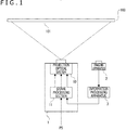
- FIG. 1 is an example of picture projection display that uses a picture projection system embodying the present technology.
- the picture projection system includes a projector 1, an imaging apparatus 2, and an information processing apparatus 3.
- FIG. 1 depicts a state in which a picture projected by the projector 1 is displayed as a projected picture 101 on a screen 100.
- the projector 1 includes a projection optical system 10 and a signal processing section 11.
- a picture signal PS sent from an external apparatus acting as a picture source is input to the signal processing section 11 of the projector 1.
- the signal processing section 11 performs various processes such as diverse correction processing, gamma processing, color processing, luminance processing, contrast adjustment, sharpness adjustment, input picture clipping for display picture generation, and scaling. In so doing, the signal processing section 11 supplies R (red), G (green), and B (blue) picture signals to the projection optical system 10.
- correction processing performed by the signal processing section 11 includes correction processes which, as will be discussed later, constitute part of the contrast adjustment.
- the R signal, G signal, and B signal as picture signals having undergone diverse corrections are supplied to the projection optical system 10.
- the projection optical system 10 includes a light source section, a light modulation section, and a projection lens system, for example. On the basis of the R, G, and B picture signals, the projection optical system 10 performs picture projection to display pictures on the screen 100.
- Any one of diverse light sources such as an LED (Light Emitting Diode), a laser light source, a xenon lamp, and a mercury lamp can be adopted as the light source section in the projection optical system 10.
- LED Light Emitting Diode
- a laser light source a laser light source
- a xenon lamp a xenon lamp
- a mercury lamp a mercury lamp
- the light modulation section of the projection optical system 10 may utilize R, G, and B liquid crystal light valves, for example. That is, the projection optical system 10 receives R, G and B picture data from the signal processing section 11; generates an R picture signal, a G picture signal, and a B picture signal as liquid crystal drive signals based on the received picture data; and supplies the generated picture signals to the R, G, and B liquid crystal light valves to display red, green, and blue pictures.
- R, G, and B liquid crystal light valves for example. That is, the projection optical system 10 receives R, G and B picture data from the signal processing section 11; generates an R picture signal, a G picture signal, and a B picture signal as liquid crystal drive signals based on the received picture data; and supplies the generated picture signals to the R, G, and B liquid crystal light valves to display red, green, and blue pictures.
- the light from the light source section is divided into R light, G light, and B light that pass through the R, G, and B liquid crystal light values, respectively, to form projection light of red, green, and blue pictures. These pictures are combined and projected by the projection lens system to the screen 100 for display as a color picture thereon.
- the projection lens system carries out focus adjustment, picture size adjustment, and projection accuracy adjustment on the projected picture.
- the projection lens system includes various lenses including a zoom lens and a focus lens, and drives these lenses to perform zoom operation, focus operation, or lens shift operation.
- the projection lens system further carries out picture size adjustment and projection angle adjustment.
- a transmissive liquid crystal projector is used as the projector 1 of the picture projection system.
- a reflective liquid crystal projector may be adopted as the projector 1.
- the imaging apparatus 2 is positioned in such a manner as to image the picture 101 projected on the screen 100.
- the imaging apparatus 2 is not necessary for the imaging apparatus 2 to be fixedly arranged.
- the imaging apparatus 2 is only required to be installed as needed when posterior degradation compensation coefficients, to be discussed later, are to be obtained.
- the imaging apparatus 2 may be configured for an operator to manually operate to image the projected picture 101 on the screen 100.
- the information processing apparatus 3 or some other control apparatus may be configured to automatically control the angle of view, imaging direction, and release timing of the imaging apparatus 2 so as to image pictures needed to calculate the posterior degradation compensation coefficient, to be discussed later.
- the information processing apparatus 3 uses the pictures imaged by the imaging apparatus 2, the information processing apparatus 3 performs calculations necessary for suppressing the reduction of contrast in the projector 1. Specifically, the posterior degradation compensation coefficient (posterior degradation compensation function) is calculated.
- the above-described information processing apparatus 3 may be either configured as a dedicated device in the picture projection system of this embodiment, or implemented using a general-purpose computer. As another alternative, the information processing apparatus 3 may be implemented using a mobile terminal apparatus such as a smartphone. In any case, an apparatus capable of arithmetic processing can be adopted as the information processing apparatus 3.
- an arithmetic processing unit such as a microcomputer performs processing based on predetermined software to obtain information necessary for executing correction operations on the projector 1 of the picture projection system.
- the information processing apparatus 3 may be either connected online continuously with the projector 1, or disconnected from networks and connected individually with only one of the components of the picture projection system. Alternatively, the information processing apparatus 3 may be temporarily connected with one of the components of the picture projection system. The information processing apparatus 3 may be further configured to exchange information with one of the components of the picture projection system via recording media.
- the picture projection system as the embodiment depicted in FIG. 1 is only an example.
- the picture projection system may be an all-in-one projector 1A including the projection optical system 10, the signal processing section 11, an imaging apparatus 2A (another form of the imaging apparatus 2), and an information processing apparatus 3A (another form of the information processing apparatus 3).
- the information processing apparatus 3A is implemented using a microcomputer, a CPU (Central Processing Unit), or a DSP (Digital Signal Processor) incorporated in the projector 1A.
- a signal processing section that performs processes, to be discussed later, for contrast adjustment may be provided outside the projector 1.
- Such a signal processing section and the information processing apparatus 3 may be integrally configured.
- the information processing apparatus 3 includes a CPU 151, a ROM (Rea Only Memory) 152, and a RAM (Random Access Memory) 153.
- the CPU 151 performs various processes in accordance with programs stored in the ROM 152 or loaded into the RAM 153 from a storage section 159.
- the RAM 153 further stores, as needed, the data necessary for the CPU 151 to execute diverse processes.
- the CPU 151, the ROM 152, and the RAM 153 are interconnected via a bus 154.
- the bus 154 is also connected with an input/output interface 155.
- the input/output interface 155 can be connected with a display 156 configured with a liquid crystal panel or an organic EL (Electroluminescence) panel, an input section 157 configured with a keyboard and a mouse, speakers 158, a storage section 159 configured with an HDD (Hard Disk Drive), and a communication section 160.
- a display 156 configured with a liquid crystal panel or an organic EL (Electroluminescence) panel
- an input section 157 configured with a keyboard and a mouse
- speakers 158 configured with a keyboard and a mouse
- a storage section 159 configured with an HDD (Hard Disk Drive)
- HDD Hard Disk Drive
- the display 156 may be either integrated with the information processing apparatus 3 or formed as a separate device.
- the display 156 displays imaged pictures, calculation results, and operation menus.
- the input section 157 is meant as an input device for use by the user who operates the information processing apparatus 3 (e.g., an operator adjusting the picture projection system).
- the communication section 160 performs wired or wireless communication with peripheral devices.
- the communication section 160 may be configured to download necessary software and to transmit diverse information by carrying out communication processing via networks including the Internet.
- the input/output interface 155 is further connected with a drive 161 as needed.
- a memory card 162 can be attached to the drive 161.
- Computer programs, for example, are read from the memory card 162 and installed into the storage section 159 as needed.
- the data processed by the CPU 151 may be stored into the memory card 162.
- the drive 161 may be a recording/reproduction drive that handles removable recording media such as magnetic disks, optical disks, and magneto-optical disks.
- the information processing apparatus 3 has a hardware configuration of a computer apparatus.
- the information processing apparatus 3 of this embodiment is not limited to the hardware configuration with a single computer apparatus as depicted in FIG. 3A .
- a plurality of computer apparatuses may be formed into a system.
- the plurality of computer apparatuses may be configured into a system via a LAN (Local Area Network).
- the plurality of computer apparatuses may be remotely located when formed into a system via VPN (Virtual Private Network) using the Internet, for example.
- the DSP may be utilized in place of the CPU 151.
- the display 156 may be provided as a simplified display attached to the projector 1A to display menu screens for selecting various functions of the projector 1A. As another alternative, the display 156 may be omitted altogether.
- the signal processing section 11 includes an arithmetic section 171, a storage section 172, and an input/output interface 173, for example.
- the arithmetic section 171 is connected with the input/output interface 173.
- the arithmetic section 171 receives data input from the outside via the input/output interface 173. Specifically, the arithmetic section 171 receives the R picture signal, G picture signal, and B picture signal.
- the arithmetic section 171 After performing predetermined processes on the RGB picture signals, the arithmetic section 171 outputs the processed picture signals to the projection optical system 10 via the input/output interface 173.
- the arithmetic section 171 uses the storage section 172 as an input buffer when receiving the RGB picture signals and as an output buffer when transmitting the processed signals.
- the storage section 172 may store the posterior degradation compensation coefficients (or function), to be discussed later.
- FIG. 4 depicts how the projection optical system 10 is configured with a light source 10a, a panel 10b acting as the light modulation section, and a projection lens 10c.
- the panel 10b as the light modulation section is implemented using LCoS (Liquid crystal on silicon: registered trademark), LCD (Liquid Crystal Display), or DLP (Digital Light Processing), for example.
- LCoS Liquid crystal on silicon: registered trademark
- LCD Liquid Crystal Display
- DLP Digital Light Processing
- the panel 10b is actually provided for each of the R, G, and B colors. In each subfigure of FIG. 4 , one of the three panels 10b is depicted.
- FIG. 4A depicts a route of light emitted from the light source 10a to pass through the panels 10b to generate R, G, and B pictures (red picture, green picture, and blue picture) that in turn transmit through the projection lens 10c to reach the screen 100.
- R, G, and B pictures red picture, green picture, and blue picture
- the light past the panels 10b and before transmitting through the projection lens 10c is indicated as an original picture X (e.g., an original red picture).
- the light past the projection lens 10c is indicated as direct light A(X).
- the original picture X differs from the direct light A(X) typically due to the scattering of light caused by the projection lens 10c.
- the direct light A(X) corresponds to the original picture X.
- FIG. 4B depicts a route of light emitted from the light source 10a to pass through the panels 10b to generate R, G, and B pictures that are scattered by the projection lens 10c and return to the panel 10b, before transmitting again through the projection lens 10c to reach the screen 100.
- the light past the projection lens 10c is indicated as scattered light B(X).
- the R light, G light, and B light can each generate scattered light.
- the scattered light B(X) corresponds to the original picture X.
- FIG. 4C depicts both the direct light A(X) and the scattered light B(X). As illustrated, the picture 101 projected on the screen 100 has the direct light A(X) and the scattered light B(X) added up altogether.
- H(X) above is a transfer function for deriving the picture 101 actually projected on the screen 100 (projected picture Y) when the picture that ought to be originally projected is the picture X.
- the correction formula H -1 (X) is implemented when appropriately set as an inverse function of the transfer function H.
- the correction formula H -1 (X) is referred to as the "posterior degradation compensation function.”
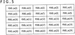
- the original picture X and the projected picture Y are each assumed to be constituted with 25 pixels, i.e., with 5 pixels in the vertical direction and 5 pixels in the horizontal direction (see FIG. 5 ), for example.
- each of the pixels is designated by a reference number as illustrated. Specifically, the pixel in the top leftmost position is indicated as “pixel px(0),” and the pixel immediately to the right thereof as “pixel px(1).”
- a pixel acting as a source of scattered light is indicated as a "scatter source pixel” and a pixel affected by scattering as a “scatter destination pixel.”
- a scatter source pixel a pixel affected by scattering
- scatter destination pixel a pixel affected by scattering
- the term yo denotes the component of light (luminance value) projected ultimately to the pixel px(0) on the screen 100 as the direct light or scattered light.
- ⁇ 0,0 is a coefficient representing the ratio of the light that ought to be projected to the pixel px(0) on the screen 100 but which is actually projected thereto without being scattered.
- ⁇ 0,1 is a coefficient representing the ratio of the light that ought to be projected to the pixel px(1) on the screen 100 but which is instead scattered and projected to the pixel px(0) on the screen 100. Thus, appear the scatter source pixel px(1) and the scatter destination pixel px(0).
- x 0 denotes the light emitted from the pixel px(0) of the panel 10b. That is, this light is the component which, of a picture signal input as the original picture X, corresponds to the pixel px(0).
- the above-mentioned coefficients ⁇ and ⁇ can be calculated with a lens design simulator using the ray tracing method, for example.
- a projector section 200 includes a test pattern generation section 200a and a projection section 200b.
- the projector section 200 is implemented with the projector 1 (see FIG. 1 ) or with the projector 1A (see FIG. 2 ), for example.
- the projection section 200b includes the projection optical system 10 and the signal processing section 11, for example.
- the test pattern generation section 200a may be in the signal processing section 11, or may be installed outside the projector section 200.
- a camera section 201 includes an imaging section 201a and a transfer function coefficient calculation section 201b.
- the camera section 201 further includes a storage section 201c that stores the coefficient ⁇ of direct light and the coefficient ⁇ of scattered light.
- the imaging section 201a is implemented with the imaging apparatus 2 or with the imaging apparatus 2A, for example.
- the transfer function coefficient calculation section 201b is implemented with the information processing apparatus 3 or with the information processing apparatus 3A.
- the picture 101 projected from the projection section 200b to the screen 100 is imaged by the imaging section 201a of the camera section 201.
- the projected picture 101 having been imaged is used to calculate the coefficients ( ⁇ and ⁇ ) of the transfer function H(X).
- the projector section 200 performs processes to project a test pattern in which only one of the 25 pixels is lit.
- the pixel to be lit is assumed to be a pixel px(j).
- step S101 the projector section 200 assigns 0 to a variable j.
- step S102 the projector section 200 performs a branching process reflecting whether or not the variable j is smaller than 25.
- step S103 the projector section 200 goes to step S103 and initializes x 0 through x 24 to 0.
- step S104 the projector section 200 performs a process of setting 1 to X j .
- step S105 the projector section 200 projects the test pattern.
- step S106 the camera section 201 images the projected picture 101 and acquires the luminance value of each pixel therein.
- the luminance value of the pixel px(0) is yo.
- the camera section 201 performs processes to calculate the coefficients ⁇ and ⁇ .
- the camera section 201 performs a process of setting 0 to a variable i in step S107.
- the variable i represents the pixel targeted (indicated as the target pixel px(i)) in a subsequent process.
- step S108 the camera section 201 determines whether or not the variable i and the variable j have the same value.
- the luminance value acquired in step 106 belongs entirely to leak light stemming from scattered light.
- the camera section 201 goes to step S109 and sets the luminance value y i acquired in step S106 to a coefficient ⁇ i, j .
- the luminance value acquired in step S106 includes not only the component of scattered light but also the component of direct light.
- the value of the coefficient ⁇ i, j is to be set appropriately in a subsequent process.
- the camera section 201 After setting the value to the coefficient ⁇ i,j in accordance with the variables i and j, the camera section 201 goes to step S111 and increments the variable i by 1. In step S112, the camera section 201 determines whether or not the variable i is smaller than 25.
- the camera section 201 repeats the processes of steps S108 to S112. On the other hand, in the case where the variable i is 25 or larger, the camera section 201 goes to the process of step S113.
- step S113 the camera section 201 performs a process of setting an appropriate value to ⁇ i, j . Specifically, the camera section 201 calculates, from the coefficient ⁇ of surrounding pixels, the component of leak light with respect to the pixel px(j).
- the camera section 201 calculates an average of coefficients ⁇ 1,0 and ⁇ 5,0 of scattered light set for the surrounding pixels px(1) and px(5) (see FIG. 5 ), and sets the average as a leak light component ⁇ 0,0 for the pixel px(0).
- the camera section 201 calculates an average of coefficients ⁇ 1, 2 , ⁇ 4, 2 and ⁇ 7, 2 of scattered light set for the surrounding pixels px(1), px(4) and px(7) (see FIG. 5 ), and sets the average as the leak light component for the pixel px(2).
- the camera section 201 calculates an average of coefficients ⁇ ,6, ⁇ 5,6, ⁇ 7,6 and ⁇ 11, 6 of scattered light set for the surrounding pixels px(1), px(5), px(7) and pixel px(11) (see FIG. 5 ), and sets the average as the leak light component for the pixel px(6).
- step S114 the camera section 201 performs a process of setting a coefficient ⁇ j,j of direct light for the pixel px(j).
- the camera section 201 subtracts the component of scattered light (i.e., coefficient ⁇ j,j ) set in step S113 above from the luminance value acquired in step S106 with respect to the pixel px(j). What is left from the subtraction is set as the component of direct light (i.e., coefficient ⁇ j,j ).
- step S102 to step S114 Every time the series of the processes from step S102 to step S114 is carried out, the coefficients ⁇ 0,j to ⁇ 24, j of scattered light and the coefficient ⁇ j, j of direct light for a given variable j are set.
- the processes of steps S102 to S114 are repeated as many times as the number that can be taken by the variable j so as to set a series of coefficients ⁇ 0,0 to ⁇ 24,24 of scattered light and a series of coefficients ⁇ 0,0 to ⁇ 24,24 of direct light.
- the camera section 201 increments the variable j by 1 in step S115 and determines whether or not the variable j is smaller than 25 in step S102.
- the camera section 201 repeats the processes of steps S103 to S115. In the case where the variable j has reached 25, the camera section 201 terminates the series of the processes depicted in FIG. 7 .
- the transfer function H(X) varies with the positions of each lens in the projector 1, the lens positions determining a zoom mode, a shift mode, and a focus mode with respect to the picture projected by the projector 1.
- each element w of the posterior degradation compensation function H -1 (X) is referred to as the posterior degradation compensation coefficient.
- the posterior degradation compensation coefficients w are obtained by calculating an inverse matrix of the matrix that includes the coefficients ⁇ and ⁇ acquired in the series of the processes in FIG. 7 .
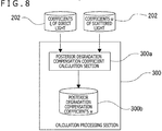
- FIG. 8 is a block diagram of a calculation processing section 300 for calculating the posterior degradation compensation coefficients w.
- the calculation processing section 300 includes a posterior degradation compensation coefficient calculation section 300a that calculates the posterior degradation compensation coefficients by acquiring relevant coefficients from the storage section 201c storing the coefficients ⁇ of direct light and the coefficients ⁇ of scattered light calculated by the camera section 201, and a storage section 300b that stores the calculated posterior degradation compensation coefficients.
- the calculation processing section 300 may be the information processing apparatus 3 depicted in FIG. 1 or the information processing apparatus 3A in FIG. 2 .
- calculation processing section 300 may be provided as part of the camera section 201 depicted in FIG. 6 or as part of the projector section 200.
- the projected picture Y' coincides with the original picture X input as the uncorrected picture signal PS.
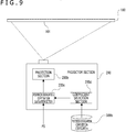
- FIG. 9 is a block diagram of the projector section 200 that applies the posterior degradation compensation function.
- the projector section 200 includes the projection section 200b, a posterior degradation compensation calculation section 200c, and a coefficient selection section 200d.
- the coefficient selection section 200d acquires the lens position of each of the lenses furnished in the projector 1, and obtains the appropriate posterior degradation compensation coefficient w corresponding to each lens position from the storage section 300b that stores the posterior degradation compensation coefficients w. Instead of acquiring the lens positions, the coefficient selection section 200d may receive a control signal from a control section such as the CPU of the projector 1 that keeps tabs on the lens positions, the coefficient selection section 200d acquiring the posterior degradation compensation coefficients w in accordance with the control signal.
- a control section such as the CPU of the projector 1 that keeps tabs on the lens positions
- the posterior degradation compensation calculation section 200c calculates the corrected picture signal PS' from the picture signal PS and from the posterior degradation compensation coefficients w.
- the projector section 200 is implemented with the projector 1 (see FIG. 1 ) or with the projector 1A (see FIG. 2 ).
- the posterior degradation compensation calculation section 200c and the coefficient selection section 200d may be provided outside the projector section 200.
- the projector 1 or 1A may be configured with the projector section 200 that includes the posterior degradation compensation calculation section 200c and the coefficient selection section 200d, as well as with the storage section 300b that stores the posterior degradation compensation coefficients w.
- the projector 1 or 1A may include the calculation processing section 300 depicted in FIG. 8 .
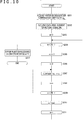
- the processes depicted in FIG. 10 are performed for each frame picture.
- the processes in FIG. 10 are carried out 30 times per second.
- step S201 the projector section 200 performs a process of acquiring a posterior degradation compensation coefficient w i,j .
- this process involves acquiring the appropriate coefficient corresponding to the lens position in the projector 1.
- the projector section 200 may acquire an appropriate posterior degradation compensation coefficient w by selecting, from among the lens positions stored in the storage section 300b, the lens position closest to the current lens position in the projector 1.
- it is possible to acquire the most appropriate posterior degradation compensation coefficient w by selecting a plurality of lens positions close to the current lens position in the projector 1 and by performing a linear interpolation on the selected lens positions.
- step S202 the projector section 200 acquires the pixel elements (X 0 ' to X 24 ') of the uncorrected picture signal PS.
- the projector section 200 proceeds to initialize a variable m to 0 (step S203), before performing a process of determining whether or not the variable m is smaller than 25.
- the variable m is used to identify the pixel to be targeted for the upcoming correction process.
- the projector section 200 performs processes of calculating an element X m ' of the corrected picture signal PS' corresponding to the calculation target pixel px(m), in step S205 and the subsequent steps.
- the projector section 200 initializes a variable sum to 0 in step S205.
- the variable sum is used when the scattered light components from different pixels are added up.
- the variable sum to which the scattered light components are added is used in ultimately calculating the element X m ' .
- step S206 the projector section 200 initializes a variable n to 0.
- the variable n is used to identify the scatter source pixel.
- the projector section 200 performs a process of adding up the scattered light components. Specifically, the projector section 200 in step S207 multiplies a posterior degradation compensation coefficient W m,n by an element X n of the uncorrected picture signal PS, and updates the variable sum by adding the product of the multiplication thereto.
- step S208 the projector section 200 increments the variable n by 1.
- step S209 the projector section 200 determines whether or not the variable n is smaller than 25. In the case where the variable n is smaller than 25, the projector section 200 repeats the processes of steps S207 to S209.
- the scattered light component of each pixel is added up to 25 or more.
- the variable n and the variable m have the same value, it means that the posterior degradation compensation coefficient w includes the component of direct light.
- the direct light component is also added up (see Math. 6).
- the projector section 200 After completing the process of adding up the direct light and the scattered light components, the projector section 200 goes to step S210 and assigns the variable sum to the element X m ' of the corrected picture signal PS'. In this manner, one element of the corrected picture signal PS' is calculated.
- step S211 the projector section 200 increments the variable m by 1, before going to step S204 to repeat the process thereof. That is, as the variable m is incremented by 1 starting from 0 up to 24, the processes of steps S204 to S211 are carried out 25 times. In this manner, the elements of the corrected picture signal PS' (X 0 ' to X 24 ') are calculated.
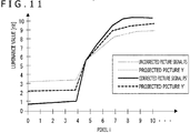
- FIG. 11 is a diagram plotting the luminance values [nit] of an uncorrected picture signal PS (original picture X), a corrected picture signal PS' (corrected picture X'), a projected picture Y, and a projected picture Y'.
- the difference in magnitude between the plotted values of the projected picture Y is smaller than that of the uncorrected picture signal PS (thin solid line). This means that in the case where the original picture X is input as the picture signal PS and projected without undergoing the above-described correction, the projected picture Y has a lower contrast than the original picture X.
- the uncorrected picture signal PS is corrected to become the corrected picture signal PS' (thick solid line) of which the difference in magnitude between the plotted values is made larger than that of the uncorrected picture signal PS (thin solid line)
- the difference in magnitude between the plotted values of the corrected projected picture Y' is made approximately the same as that of the original picture X (thin solid line).
- the above-described method of calculating the transfer function H(X) involves, for example, executing the test pattern with only one pixel lit therein as many times as the number of pixels in the picture. Specifically discussed above is the example of 25 pixels constituted with 5 pixels in the vertical direction and 5 pixels in the horizontal direction. Thus, the example involves having 25 test patterns generated and projected to the screen 100 and getting the projected test patterns imaged.
- the values u c and v c are calculated for each test pattern and can be uniquely determined by the test pattern. That is, these values may be calculated without actually projecting the test patterns.
- the unknowns are calculated by solving three simultaneous equations that include the numbers ⁇ c,c , a c , and b c .
- a test pattern TP1 is a pattern such that the ratio of white-lit pixels to unlit black pixels is 0:10. That is, all pixels are unlit.
- a test pattern TP2 is a pattern with its outer circumference lit in such a manner that the ratio of white-lit pixels to unlit black pixels is 1:9.
- a test pattern TP3 is a pattern with its outer circumference lit in such a manner that the ratio of white-lit pixels to unlit black pixels is 2:8.
- test pattern TP4 (lit/unlit ratio is 3:7)
- a test pattern TP5 (lit/unlit ratio is 4:6)
- a test pattern TP6 (lit/unlit ratio is 5:5)
- a test pattern TP7 (lit/unlit ratio is 6:4)
- a test pattern TP8 (lit/unlit ratio is 7:3)
- a test pattern TP9 (lit/unlit ratio is 8:2)
- a test pattern TP10 (lit/unlit ratio is 9:1).
- test patterns are projected to the screen 100. That is, the test pattern for use in step S105 in FIG. 7 is selected from the above-described 10 test patterns. The processes of steps S106 to S114 are then performed on the selected test pattern.
- steps S106 to S114 are performed 10 times in a loop.
- This provides 10 formulas, which are used to calculate the unknown numbers ⁇ c,c , a c , and b c .
- steps S107 to S112 are carried out in a loop as many times as the number of pixels in the picture, with the variable i incremented successively.
- the processes need to be performed approximately 8 million times in a loop.
- the target pixel px(i) in the preceding example is replaced, in this example of simplification, with a sub-region as a target region I including a plurality of pixels including the pixel px(i).
- An average of the luminance values of the target region I (average luminance value Y I ) is then calculated.
- a given pixel px(c) is regarded as the target pixel, so that the target sub-region is a target region C as a sub-region including the given pixel px(c).
- the value Y c, 10% is a luminance value measured by use of the test pattern TP2 in which the lit pixels constitute a 10% region.
- the values u c, 10% and v c, 10% are values that can be calculated beforehand for the test pattern TP2. It is to be noted that the term e 10% represents an error term.
- the three unknown numbers ( ⁇ c,c , a c , b c ) are calculated by solving 10 simultaneous equations indicated as Math. 10 above.
- the three unknowns may be calculated more accurately by use of the least-square method.
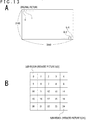
- the picture based on the uncorrected picture signal PS (original picture) is divided into a plurality of sub-regions.
- the picture derived from each sub-region is indicated as a reduced picture.
- FIG. 13A depicts an original picture constituted with 2,160 pixels in the vertical direction and 3,840 pixels in the horizontal direction amounting to approximately 8 million pixels.
- the posterior degradation compensation coefficient w of the pixel px(n) as one of the pixels in a reduced picture S(k) is approximated using the following mathematical formula: w c , n
- W c,k is regarded as the posterior degradation compensation coefficient corresponding to the reduced picture.
- a picture X i based on the reduced picture is known to be obtained quickly using the Integral Image technique, for example.
- the terms ⁇ c and W c,k obtained here are used in conjunction with 1+g coefficients and Math. 17 above to rapidly calculate the element x i ' of each pixel in the corrected picture signal PS'.
- the present technology permits suppression of the reduction of contrast due to the scattered light stemming from signal processing. Besides that, the technology improves the picture quality by suppressing ghost components. Further, the technology suppresses the mixing of colors (so as to improve color reproducibility).
- the present technology can be used for preventing diverse kinds of degradation in the case where pictures are projected to a curved surface such as a dome-shaped surface.
- the present technology can be applied to cases in which the components of light to be projected to other pixels affect these pixels due to light reflection in the room.
- the present technology can be applied to all kinds of displays where scattered light can occur, as in the case of LCDs with their backlight reflection.
- a signal processing apparatus of the embodiment e.g., an apparatus equipped with the signal processing section 11 depicted in FIG. 1 or 2 , such as the projector 1 or 1A
- the signal processing apparatus includes a coefficient acquisition section (coefficient selection section 200d) that acquires a posterior degradation compensation coefficient for compensating the degradation due to scattered light in the picture 101 projected by the picture projection section (projection section 200b), the scattered light being caused by the picture projection section; and a compensation coefficient application section (posterior degradation compensation calculation section 200c) that applies the posterior degradation compensation coefficient to the picture input signal (picture signal PS) input to the picture projection section that in turn outputs projection light.
- coefficient acquisition section coefficient selection section 200d
- projection section 200b posterior degradation compensation coefficient for compensating the degradation due to scattered light in the picture 101 projected by the picture projection section
- compensation section 200c compensation coefficient application section that applies the posterior degradation compensation coefficient to the picture input signal (picture signal PS) input to the picture projection section that in turn outputs projection light.
- the coefficient acquisition section acquires a posterior degradation compensation coefficient such as to compensate the reduction of contrast due to the occurrence of scattered light, for example, and the compensation coefficient application section applies the posterior degradation compensation coefficient to the picture signal PS.
- the compensated projected picture is given an appropriate contrast and thereby made equivalent to the picture to be originally projected (original picture X).
- the signal processing apparatus of the embodiment includes the compensation coefficient selection section (coefficient selection section 200d) that selects the posterior degradation compensation coefficient applied by the compensation coefficient application section (posterior degradation compensation calculation section 200c) in accordance with the positions of lenses in the picture projection section (projection section 200b), the lens positions determining zoom mode, shift mode, and focus mode with respect to the projected picture 101.
- coefficient selection section 200d that selects the posterior degradation compensation coefficient applied by the compensation coefficient application section (posterior degradation compensation calculation section 200c) in accordance with the positions of lenses in the picture projection section (projection section 200b), the lens positions determining zoom mode, shift mode, and focus mode with respect to the projected picture 101.
- the model of scattered light attributable to the lens may become a different scattered light model due to a different lens position.
- the signal processing apparatus acquires and applies the posterior degradation compensation coefficient corresponding to the lens position, it is possible to perform an optimum compensation process on the picture signal PS and thereby to optimize the projected picture 101.
- the compensation coefficient selection section may select the posterior degradation compensation coefficient calculated using a plurality of posterior degradation compensation coefficients established with respect to the lens positions.
- this configuration permits calculation of the posterior degradation compensation coefficient corresponding to the lens position for implementing 2.5x zoom mode from both the posterior degradation compensation coefficient corresponding to the lens position for implementing 2x zoom mode and the posterior degradation compensation coefficient corresponding to the lens position for implementing 3x zoom mode.
- the newly calculated posterior degradation compensation coefficient is selected by the compensation coefficient selection section.
- the signal processing apparatus of the embodiment may include the storage section 172 that stores the posterior degradation compensation coefficients.
- the storage section 172 storing the posterior degradation compensation coefficients When the storage section 172 storing the posterior degradation compensation coefficients is included in the signal processing apparatus, there is no need for the signal processing apparatus to conduct communications to acquire the posterior degradation compensation coefficients. With appropriate posterior degradation compensation coefficients acquired from the storage section 172, the processing is performed smoothly.
- the signal processing apparatus of the embodiment may include the test pattern generation section 200a for generating test patterns used to calculate the posterior degradation compensation coefficients.
- test pattern generation section 200a there is no need to acquire test patterns from the outside.
- the projector 1 or 1A equipped with the signal processing apparatus of the embodiment has the posterior degradation compensation coefficients calculated beforehand at the factory or at the installation site and stored in the storage section. That is, adjustment steps are provided in which the posterior degradation compensation coefficients are calculated and stored prior to actual operation.
- having the test pattern generation section 200a included in the projector 1 or 1A eliminates the need for an external terminal in the adjustment steps at the factory or at the installation site. That is, the adjustment steps are simplified.
- the test pattern may be a picture pattern in which only one pixel is lit.
- the work of projecting the picture pattern in which only one pixel is lit may be performed as many times as the number of pixels in the picture, the lit pixel being changed every time. This makes it possible to acquire the posterior degradation compensation coefficients for implementing the most powerful correction process. Such a procedure is effective, for example, in the case where an extended time can be allocated to the work of acquiring posterior degradation compensation coefficients in the adjustment steps.
- the test pattern may be a picture pattern in which a predetermined proportion of the pixels are lit starting from the outer circumference of the projected picture 101.
- the compensation coefficient application section may apply the posterior degradation compensation coefficient calculated using a linear first approximation equation based on the distance (d i,j ) between the scatter source pixel px(j) originating scattered light and the scatter destination pixel px(i) affected by the scattered light.
- the compensation coefficient application section may apply the posterior degradation compensation coefficient calculated by measuring the luminance value of a specific region (target sub-region), instead of the posterior degradation compensation coefficient calculated by measuring the luminance values of all pixels included in the projected picture 101.
- the adjustment steps can be shortened in the case where the posterior degradation compensation coefficients are calculated in these steps.
- the compensation coefficient application section may divide one frame of the picture input signal (picture signal PS) into units of a sub-region including a plurality of pixels in the projected picture, the compensation coefficient application section further applying the corresponding posterior degradation compensation coefficient to each of the sub-regions.
- the processing load on the arithmetic section 171 is alleviated. This reduces generation of heat from the arithmetic section 171.
- the amount of calculation for obtaining the corrected picture signal PS' is increased. In some cases, the number of times the frame update is performed per second is required to be limited depending on the amount of calculation.
- the limit on the frame update count can still be reduced by simplifying the application of the posterior degradation compensation function to the picture signal using this configuration.
- the signal processing apparatus of the embodiment may include the picture projection section (projection section 200b) so as to function as the projector apparatus (projector 1 or 1A).
- the signal processing apparatus acts as the projector apparatus that internally performs the process of generating the corrected picture signal PS' at the time of picture projection. That is, the corrected picture signal PS' can be generated without recourse to an external apparatus.
- the posterior degradation compensation coefficients stored in an internal storage area of the projector apparatus there is no need to rely on an external apparatus for the process of acquiring these coefficients. This eliminates the constraints, imposed by use of an external apparatus, on the operating environment of the projector apparatus.
- the imaging apparatus 2 or 2A and the information processing apparatus 3 or 3A are configured with the projector apparatus as depicted in FIG. 2
- the projector apparatus alone can take over the projection and imaging of test patterns and the calculation of posterior degradation compensation coefficients. This optimizes the adjustment steps.
- H(X) denotes the transfer function of the projected picture 101
- an inverse function of the transfer function H(X) may be used as the posterior degradation compensation function of which the elements are the posterior degradation compensation coefficients.
- a program of the embodiment causes the arithmetic section 171 to perform a compensation coefficient application process that applies a posterior degradation compensation coefficient to a picture input signal (picture signal PS) input to a picture projection section (projection section 200b), the posterior degradation compensation coefficient being based on scattered light caused by the picture projection section in a picture projected by the picture projection section.
- the program of the embodiment may cause the arithmetic section 171 to perform a coefficient acquisition process that acquires a posterior degradation compensation coefficient for compensating the degradation due to scattered light in the picture 101 projected by the picture projection section (projection section 200b), the scattered light being caused by the picture projection section, the program further causing the arithmetic section 171 to perform a compensation coefficient application process that applies the posterior degradation compensation coefficient to the picture input signal (picture signal PS) input to the picture projection section that in turn outputs projection light.
- a compensation coefficient application process that applies the posterior degradation compensation coefficient to the picture input signal (picture signal PS) input to the picture projection section that in turn outputs projection light.
- the program causes the arithmetic section 171 to perform the processes of steps S201 to S211 in FIG. 10 .
- These processes may be replaced with those explained above in connection with the simplification of application of the posterior degradation compensation function to the picture signal.
- Such a program may be stored beforehand on an HDD as a storage medium incorporated in equipment such as a computer apparatus, or in a ROM in a microcomputer furnished with a CPU.
- the program may be held (stored) temporarily or permanently on removable recording media such as a semiconductor memory, a memory card, an optical disk, a magneto-optical disk, or a magnetic disk.
- removable storage media may be offered as what is called packaged software.
- the program may be downloaded from a download site via networks such as a LAN or the Internet.
- the present technology may be implemented preferably in the following configurations:
Landscapes
- Engineering & Computer Science (AREA)
- Multimedia (AREA)
- Signal Processing (AREA)
- Physics & Mathematics (AREA)
- General Physics & Mathematics (AREA)
- Theoretical Computer Science (AREA)
- Computer Hardware Design (AREA)
- Transforming Electric Information Into Light Information (AREA)
- Controls And Circuits For Display Device (AREA)
- Projection Apparatus (AREA)
Applications Claiming Priority (2)
| Application Number | Priority Date | Filing Date | Title |
|---|---|---|---|
| JP2018064442 | 2018-03-29 | ||
| PCT/JP2019/001067 WO2019187511A1 (fr) | 2018-03-29 | 2019-01-16 | Dispositif de traitement de signal, procédé de traitement d'informations, et programme |
Publications (2)
| Publication Number | Publication Date |
|---|---|
| EP3780585A1 true EP3780585A1 (fr) | 2021-02-17 |
| EP3780585A4 EP3780585A4 (fr) | 2021-05-26 |
Family
ID=68058098
Family Applications (1)
| Application Number | Title | Priority Date | Filing Date |
|---|---|---|---|
| EP19774697.7A Withdrawn EP3780585A4 (fr) | 2018-03-29 | 2019-01-16 | Dispositif de traitement de signal, procédé de traitement d'informations, et programme |
Country Status (5)
| Country | Link |
|---|---|
| US (1) | US20210051305A1 (fr) |
| EP (1) | EP3780585A4 (fr) |
| JP (1) | JPWO2019187511A1 (fr) |
| CN (1) | CN111903120A (fr) |
| WO (1) | WO2019187511A1 (fr) |
Cited By (1)
| Publication number | Priority date | Publication date | Assignee | Title |
|---|---|---|---|---|
| US20230025629A1 (en) * | 2021-07-26 | 2023-01-26 | Seiko Epson Corporation | Method of controlling projector and projector |
Families Citing this family (4)
| Publication number | Priority date | Publication date | Assignee | Title |
|---|---|---|---|---|
| JP2020150303A (ja) * | 2019-03-11 | 2020-09-17 | ソニー株式会社 | 画像処理装置、画像処理方法、およびプログラム |
| TWI759669B (zh) * | 2019-12-23 | 2022-04-01 | 中強光電股份有限公司 | 顯示畫面檢測方法與顯示畫面檢測系統 |
| JP7468133B2 (ja) * | 2020-05-18 | 2024-04-16 | セイコーエプソン株式会社 | 投写光学装置、プロジェクター、および投写光学装置の制御方法 |
| JP2025525461A (ja) * | 2022-06-30 | 2025-08-05 | フライトセイフティ・インターナショナル・インコーポレイテッド | 画像処理のシステム、方法、および装置 |
Family Cites Families (11)
| Publication number | Priority date | Publication date | Assignee | Title |
|---|---|---|---|---|
| JP3960142B2 (ja) | 2002-06-24 | 2007-08-15 | セイコーエプソン株式会社 | 画像表示装置、プロジェクタ、プログラム及び記憶媒体 |
| JP4591751B2 (ja) * | 2004-06-10 | 2010-12-01 | ソニー株式会社 | 画像投射システム及び画像投射装置 |
| US20070115440A1 (en) * | 2005-11-21 | 2007-05-24 | Microvision, Inc. | Projection display with screen compensation |
| JP5140869B2 (ja) * | 2007-08-06 | 2013-02-13 | 株式会社リコー | 画像投影方法および画像投影装置 |
| US8106949B2 (en) * | 2009-03-26 | 2012-01-31 | Seiko Epson Corporation | Small memory footprint light transport matrix capture |
| JP5407623B2 (ja) * | 2009-07-16 | 2014-02-05 | 富士通セミコンダクター株式会社 | マスクパターン評価方法、マスクパターン補正方法及びマスクパターン発生装置 |
| US20120200673A1 (en) * | 2010-06-15 | 2012-08-09 | Junichi Tagawa | Imaging apparatus and imaging method |
| JP6361111B2 (ja) * | 2013-10-31 | 2018-07-25 | 株式会社Jvcケンウッド | 画像処理装置、画像処理方法および投射装置 |
| JP6071974B2 (ja) * | 2014-10-21 | 2017-02-01 | キヤノン株式会社 | 画像処理方法、画像処理装置、撮像装置および画像処理プログラム |
| JP6469130B2 (ja) * | 2014-11-10 | 2019-02-13 | マクセル株式会社 | プロジェクタ及び映像表示方法 |
| WO2016157671A1 (fr) * | 2015-03-27 | 2016-10-06 | ソニー株式会社 | Dispositif de traitement d'informations, procédé de traitement d'informations, programme, et dispositif d'affichage d'image |
-
2019
- 2019-01-16 US US16/982,253 patent/US20210051305A1/en not_active Abandoned
- 2019-01-16 WO PCT/JP2019/001067 patent/WO2019187511A1/fr not_active Ceased
- 2019-01-16 CN CN201980021189.3A patent/CN111903120A/zh not_active Withdrawn
- 2019-01-16 JP JP2020509696A patent/JPWO2019187511A1/ja active Pending
- 2019-01-16 EP EP19774697.7A patent/EP3780585A4/fr not_active Withdrawn
Cited By (2)
| Publication number | Priority date | Publication date | Assignee | Title |
|---|---|---|---|---|
| US20230025629A1 (en) * | 2021-07-26 | 2023-01-26 | Seiko Epson Corporation | Method of controlling projector and projector |
| US11778152B2 (en) * | 2021-07-26 | 2023-10-03 | Seiko Epson Corporation | Method of controlling projector and projector |
Also Published As
| Publication number | Publication date |
|---|---|
| JPWO2019187511A1 (ja) | 2021-04-15 |
| WO2019187511A1 (fr) | 2019-10-03 |
| EP3780585A4 (fr) | 2021-05-26 |
| US20210051305A1 (en) | 2021-02-18 |
| CN111903120A (zh) | 2020-11-06 |
Similar Documents
| Publication | Publication Date | Title |
|---|---|---|
| EP3780585A1 (fr) | Dispositif de traitement de signal, procédé de traitement d'informations, et programme | |
| US6704008B2 (en) | Non-uniformity correction for displayed images | |
| CN113724652B (zh) | OLED显示面板Mura的补偿方法、装置及可读介质 | |
| JP7660348B2 (ja) | 投影システム及びその映像均一度補償方法 | |
| JP5603014B2 (ja) | 超解像表示の補正 | |
| JP2015097350A (ja) | 画像処理装置およびマルチプロジェクションシステム | |
| JP2003295812A (ja) | 映像の輝度変更方法及びその装置 | |
| JP2012123085A (ja) | マルチ画面表示装置 | |
| CN116442523B (zh) | 一种光均匀性调节方法、装置、设备和存储介质 | |
| JP6794983B2 (ja) | 情報処理装置、情報処理方法、プログラム、及び画像表示装置 | |
| JP2016075883A (ja) | 投影システム、投影装置、投影方法、及びプログラム | |
| EP1699035A1 (fr) | Systeme d'affichage | |
| JP2005150779A (ja) | 画像表示装置の表示特性補正データ算出方法、表示特性補正データプログラム、表示特性補正データ算出装置 | |
| US10948809B2 (en) | Image projection apparatus, its control method, and storage medium | |
| US20020180765A1 (en) | Image signal processing apparatus, image display apparatus, multidisplay apparatus, and chromaticity adjustment method for use in the multidisplay apparatus | |
| US20070297689A1 (en) | Integrated histogram auto adaptive contrast control (ACC) | |
| JP2007081611A (ja) | 表示画面補正パラメータ設定方法 | |
| JP2025002778A (ja) | 投射型表示装置及び映像補正方法 | |
| US11138702B2 (en) | Information processing apparatus, information processing method and non-transitory computer readable storage medium | |
| JP2021157070A (ja) | 画像表示装置および画像表示装置の制御方法 | |
| CN119649735B (zh) | 一种显示面板补偿方法、装置、终端设备及计算机程序产品 | |
| CN117524136B (zh) | 用于显示面板补偿的图像的获取方法及图像获取装置 | |
| JP2019082509A (ja) | 画像表示装置および画像表示装置の制御方法 | |
| JP2005157260A (ja) | 輝度調整方法 | |
| JP2024158324A (ja) | 画像処理装置、画像処理装置の制御方法、およびプログラム |
Legal Events
| Date | Code | Title | Description |
|---|---|---|---|
| STAA | Information on the status of an ep patent application or granted ep patent |
Free format text: STATUS: THE INTERNATIONAL PUBLICATION HAS BEEN MADE |
|
| PUAI | Public reference made under article 153(3) epc to a published international application that has entered the european phase |
Free format text: ORIGINAL CODE: 0009012 |
|
| STAA | Information on the status of an ep patent application or granted ep patent |
Free format text: STATUS: REQUEST FOR EXAMINATION WAS MADE |
|
| 17P | Request for examination filed |
Effective date: 20200906 |
|
| AK | Designated contracting states |
Kind code of ref document: A1 Designated state(s): AL AT BE BG CH CY CZ DE DK EE ES FI FR GB GR HR HU IE IS IT LI LT LU LV MC MK MT NL NO PL PT RO RS SE SI SK SM TR |
|
| AX | Request for extension of the european patent |
Extension state: BA ME |
|
| A4 | Supplementary search report drawn up and despatched |
Effective date: 20210422 |
|
| RIC1 | Information provided on ipc code assigned before grant |
Ipc: H04N 5/74 20060101AFI20210416BHEP Ipc: G03B 21/14 20060101ALI20210416BHEP Ipc: G09G 5/00 20060101ALI20210416BHEP Ipc: G09G 5/10 20060101ALI20210416BHEP Ipc: H04N 9/31 20060101ALI20210416BHEP |
|
| DAV | Request for validation of the european patent (deleted) | ||
| DAX | Request for extension of the european patent (deleted) | ||
| RAP3 | Party data changed (applicant data changed or rights of an application transferred) |
Owner name: SONY GROUP CORPORATION |
|
| STAA | Information on the status of an ep patent application or granted ep patent |
Free format text: STATUS: THE APPLICATION HAS BEEN WITHDRAWN |
|
| 18W | Application withdrawn |
Effective date: 20220816 |