EP3780762A1 - Procédé de configuration de canal de commande de liaison descendante physique, équipement utilisateur et dispositif côté réseau - Google Patents
Procédé de configuration de canal de commande de liaison descendante physique, équipement utilisateur et dispositif côté réseau Download PDFInfo
- Publication number
- EP3780762A1 EP3780762A1 EP19776447.5A EP19776447A EP3780762A1 EP 3780762 A1 EP3780762 A1 EP 3780762A1 EP 19776447 A EP19776447 A EP 19776447A EP 3780762 A1 EP3780762 A1 EP 3780762A1
- Authority
- EP
- European Patent Office
- Prior art keywords
- dci format
- pdcch
- serving cell
- schedule
- search space
- Prior art date
- Legal status (The legal status is an assumption and is not a legal conclusion. Google has not performed a legal analysis and makes no representation as to the accuracy of the status listed.)
- Granted
Links
Images


Classifications
-
- H—ELECTRICITY
- H04—ELECTRIC COMMUNICATION TECHNIQUE
- H04L—TRANSMISSION OF DIGITAL INFORMATION, e.g. TELEGRAPHIC COMMUNICATION
- H04L5/00—Arrangements affording multiple use of the transmission path
- H04L5/003—Arrangements for allocating sub-channels of the transmission path
- H04L5/0053—Allocation of signalling, i.e. of overhead other than pilot signals
-
- H—ELECTRICITY
- H04—ELECTRIC COMMUNICATION TECHNIQUE
- H04L—TRANSMISSION OF DIGITAL INFORMATION, e.g. TELEGRAPHIC COMMUNICATION
- H04L5/00—Arrangements affording multiple use of the transmission path
- H04L5/0091—Signalling for the administration of the divided path, e.g. signalling of configuration information
- H04L5/0094—Indication of how sub-channels of the path are allocated
-
- H—ELECTRICITY
- H04—ELECTRIC COMMUNICATION TECHNIQUE
- H04W—WIRELESS COMMUNICATION NETWORKS
- H04W72/00—Local resource management
- H04W72/20—Control channels or signalling for resource management
- H04W72/23—Control channels or signalling for resource management in the downlink direction of a wireless link, i.e. towards a terminal
-
- H—ELECTRICITY
- H04—ELECTRIC COMMUNICATION TECHNIQUE
- H04W—WIRELESS COMMUNICATION NETWORKS
- H04W52/00—Power management, e.g. Transmission Power Control [TPC] or power classes
- H04W52/02—Power saving arrangements
- H04W52/0209—Power saving arrangements in terminal devices
-
- H—ELECTRICITY
- H04—ELECTRIC COMMUNICATION TECHNIQUE
- H04W—WIRELESS COMMUNICATION NETWORKS
- H04W52/00—Power management, e.g. Transmission Power Control [TPC] or power classes
- H04W52/02—Power saving arrangements
- H04W52/0209—Power saving arrangements in terminal devices
- H04W52/0212—Power saving arrangements in terminal devices managed by the network, e.g. network or access point is leader and terminal is follower
- H04W52/0216—Power saving arrangements in terminal devices managed by the network, e.g. network or access point is leader and terminal is follower using a pre-established activity schedule, e.g. traffic indication frame
-
- H—ELECTRICITY
- H04—ELECTRIC COMMUNICATION TECHNIQUE
- H04W—WIRELESS COMMUNICATION NETWORKS
- H04W52/00—Power management, e.g. Transmission Power Control [TPC] or power classes
- H04W52/02—Power saving arrangements
- H04W52/0209—Power saving arrangements in terminal devices
- H04W52/0225—Power saving arrangements in terminal devices using monitoring of external events, e.g. the presence of a signal
- H04W52/0229—Power saving arrangements in terminal devices using monitoring of external events, e.g. the presence of a signal where the received signal is a wanted signal
-
- H—ELECTRICITY
- H04—ELECTRIC COMMUNICATION TECHNIQUE
- H04W—WIRELESS COMMUNICATION NETWORKS
- H04W52/00—Power management, e.g. Transmission Power Control [TPC] or power classes
- H04W52/02—Power saving arrangements
- H04W52/0209—Power saving arrangements in terminal devices
- H04W52/0261—Power saving arrangements in terminal devices managing power supply demand, e.g. depending on battery level
- H04W52/0274—Power saving arrangements in terminal devices managing power supply demand, e.g. depending on battery level by switching on or off the equipment or parts thereof
- H04W52/028—Power saving arrangements in terminal devices managing power supply demand, e.g. depending on battery level by switching on or off the equipment or parts thereof switching on or off only a part of the equipment circuit blocks
-
- Y—GENERAL TAGGING OF NEW TECHNOLOGICAL DEVELOPMENTS; GENERAL TAGGING OF CROSS-SECTIONAL TECHNOLOGIES SPANNING OVER SEVERAL SECTIONS OF THE IPC; TECHNICAL SUBJECTS COVERED BY FORMER USPC CROSS-REFERENCE ART COLLECTIONS [XRACs] AND DIGESTS
- Y02—TECHNOLOGIES OR APPLICATIONS FOR MITIGATION OR ADAPTATION AGAINST CLIMATE CHANGE
- Y02D—CLIMATE CHANGE MITIGATION TECHNOLOGIES IN INFORMATION AND COMMUNICATION TECHNOLOGIES [ICT], I.E. INFORMATION AND COMMUNICATION TECHNOLOGIES AIMING AT THE REDUCTION OF THEIR OWN ENERGY USE
- Y02D30/00—Reducing energy consumption in communication networks
- Y02D30/70—Reducing energy consumption in communication networks in wireless communication networks
Definitions
- Embodiments of the present disclosure relate to the field of communications technologies, and in particular, to a method for configuring a physical downlink control channel (Physical Downlink Control Channel, PDCCH), user equipment, and a network side device.
- PDCCH Physical Downlink Control Channel
- different monitoring periods can be configured for different PDCCH search spaces (Search Space, SS), and configurable monitoring periods include one slot, two slots, four slots, five slots, eight slots, ten slots, sixteen slots, and twenty slots.
- Services of user equipment (User Equipment, UE) are random. For example, at some moments, there are many downlink services, and downlink data packets also arrive frequently. In this case, the UE needs to frequently monitor a PDCCH on which downlink scheduling (scheduling of a PDSCH) is performed, to receive the downlink data packets.
- DCI formats for example, a DCI format 0_1 and a DCI format 1_1
- DCI format 0_1 and a DCI format 1_1 are configured with a same monitoring period. If the configured monitoring period is ten slots, the UE needs to monitor the DCI format 0_1 and the DCI format 1_1 every ten slots.
- control channel element control channel element, CCE
- Aggregation Level, AL are configured with a same monitoring period, and therefore the UE monitors unnecessary DCI formats or CCE aggregation levels.
- a control resource set (CORESET) of a PDCCH to be monitored by the user equipment a search space of the to-be-monitored PDCCH, a DCI format in the search space of the to-be-monitored PDCCH, a CCE aggregation level in the search space of the to-be-monitored PDCCH, an association relationship between the search space of the to-be-monitored PDCCH and the CORESET of the to-be-monitored PDCCH, and the like, are configured by using RRC signaling.
- a latency of the RRC signaling is relatively high, and the RRC signaling only supports a semi-static change in the above configuration parameters, and cannot quickly change the above configuration parameters.
- An objective of embodiments of the present disclosure is to provide a method for monitoring a physical downlink control channel, user equipment, and a network side device, to reduce unnecessary PDCCH monitoring.
- a method for monitoring a physical downlink control channel is provided, and the method is applied to user equipment and includes:
- a method for monitoring a physical downlink control channel is further provided, and the method is applied to user equipment and includes:
- a method for configuring a physical downlink control channel is further provided, and the method is applied to a network side device and includes: sending physical layer signaling or media access control (MAC) layer signaling to user equipment, where the physical layer signaling or the media access control (MAC) layer signaling is used by the user equipment to determine a first parameter related to a PDCCH monitoring behavior of a serving cell, and the first parameter includes at least one of the following:
- a method for configuring a physical downlink control channel is further provided, and the method is applied to a network side device and includes: sending RRC signaling to user equipment, where the RRC signaling is used by the user equipment to determine a monitoring parameter, and the monitoring parameter is associated with at least one of a downlink control information (DCI) format of a PDCCH to be monitored by the user equipment, a control channel element (CCE) aggregation level of the to-be-monitored PDCCH, and a CCE aggregation level of the DCI format of the to-be-monitored PDCCH.
- DCI downlink control information
- CCE control channel element
- user equipment including:
- user equipment including:
- a network side device including: a first sending module, configured to send physical layer signaling or media access control (MAC) layer signaling to user equipment, where the physical layer signaling or the media access control (MAC) layer signaling is used by the user equipment to determine a first parameter related to a PDCCH monitoring behavior of a serving cell, and the first parameter includes at least one of the following:
- a network side device including: a third sending module, configured to send RRC signaling to user equipment, where the RRC signaling is used by the user equipment to determine a monitoring parameter, and the monitoring parameter is associated with at least one of a downlink control information (DCI) format of a PDCCH to be monitored by the user equipment, a control channel element (CCE) aggregation level of the to-be-monitored PDCCH, and a CCE aggregation level of the DCI format of the to-be-monitored PDCCH.
- DCI downlink control information
- CCE control channel element
- user equipment including: a processor, a memory, and a computer program that is stored in the memory and configured to run on the processor, where the computer program, when executed by the processor, implements steps of the method for monitoring a PDCCH in the first aspect or the second aspect.
- a network side device including: a processor, a memory, and a computer program that is stored in the memory and configured to run on the processor, where the computer program, when executed by the processor, implements steps of the method for configuring a PDCCH in the third aspect or the fourth aspect.
- a computer readable storage medium stores a computer program, and the computer program, when executed by a processor, implements steps of the method for monitoring or configuring a PDCCH in the first aspect, the second aspect, the third aspect, or the fourth aspect.
- the word such as “exemplary” or “example” is used to represent giving an example, an illustration, or a description. Any embodiment or design scheme described as an “exemplary” or “example” in the embodiments of the present disclosure should not be explained as being more preferred or having more advantages than another embodiment or design scheme. Exactly, use of the word such as “exemplary” or “example” is intended to present a concept in a specific manner.
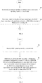
- FIG. 1 is a schematic structural diagram of a wireless communications system according to an embodiment of the present disclosure.
- the wireless communications system may include a network side device 10 and user equipment.
- the user equipment is denoted as UE 11, and the UE 11 may be connected to the network side device 10.
- a connection between the devices is a wireless connection.
- solid lines are used for illustration in FIG. 1 .
- the above communications system may include a plurality of UEs, and the network side device may communicate with the plurality of UEs (transmit signaling or data).
- the network side device 10 provided in this embodiment of the present disclosure may be a base station, and the base station may be a commonly used base station, or may be an evolved node base station (evolved node base station, eNB), or may be a device such as a network side device in a 5G system (for example, a next generation node base station (next generation node base station, gNB) or a transmission and reception point (transmission and reception point, TRP)).
- eNB evolved node base station
- gNB next generation node base station
- TRP transmission and reception point
- the user equipment provided in this embodiment of the present disclosure may be a mobile phone, a tablet computer, a notebook computer, an ultra-mobile personal computer (Ultra-Mobile Personal Computer, UMPC), a netbook, a personal digital assistant (Personal Digital Assistant, PDA), or the like.
- UMPC Ultra-Mobile Personal Computer
- PDA Personal Digital Assistant
- FIG. 2 shows a procedure of a method for monitoring a PDCCH according to an embodiment of the present disclosure. The method is performed by UE, and specific steps are as follows:
- the first parameter related to the PDCCH monitoring behavior of the serving cell includes at least one of the following:
- the search space may be a common search space or a UE-specific search space.
- the UE can dynamically disable or configure or reconfigure one or more search spaces or CORESETs by receiving a media access control control element or DCI, thereby avoiding unnecessary monitoring of a plurality of search spaces or CORESETs of different reception points by the UE when there are fewer services.
- RRC Radio Resource Control
- the method further includes: determining a monitoring parameter based on the physical layer signaling or the MAC layer signaling, where the monitoring parameter is associated with at least one of a downlink control information (DCI) format of a PDCCH to be monitored by the user equipment, a control channel element (CCE) aggregation level of the to-be-monitored PDCCH, and a CCE aggregation level of the DCI format of the to-be-monitored PDCCH, for example, there is a one-to-one correspondence between the monitoring parameter and the at least one of the downlink control information (DCI) format of the PDCCH to be monitored by the user equipment, the control channel element (CCE) aggregation level of the to-be-monitored PDCCH, and the CCE aggregation level of the DCI format of the to-be-monitored PDCCH.
- DCI downlink control information
- CCE control channel element
- the UE may monitor the PDCCH based on the monitoring parameter.
- the method further includes: receiving radio resource control (RRC) signaling sent by the network side; and determining, based on the RRC signaling, a second parameter related to the PDCCH monitoring behavior of the serving cell, where the second parameter includes at least one of the following: the control resource set (CORESET) of the to-be-monitored PDCCH; the search space of the to-be-monitored PDCCH; the DCI format in the search space of the to-be-monitored PDCCH; the CCE aggregation level in the search space of the to-be-monitored PDCCH; and the association relationship between the search space of the to-be-monitored PDCCH and the CORESET of the to-be-monitored PDCCH.
- RRC radio resource control
- the DCI format includes at least one of the following:
- the DCI format in this embodiment of the present disclosure is the DCI format 0_1 and the DCI format 1_1 of the UE-specific search space
- different monitoring parameters may be configured for the DCI format 0_1 and the DCI format 1_1. For example, at least one of monitoring periods, monitoring offsets, and monitoring patterns within a slot configured for the DCI format 0_1 and the DCI format 1_1 may be different.
- the monitoring parameter includes at least one of the following: a monitoring period, a monitoring offset, and a monitoring pattern within a slot, where the monitoring pattern within a slot is used to indicate one or more time-domain symbols in a CORESET for PDCCH monitoring in a slot.
- a monitoring period a monitoring offset
- a monitoring pattern within a slot is used to indicate one or more time-domain symbols in a CORESET for PDCCH monitoring in a slot.
- a unit of the monitoring period may be a slot or milliseconds (ms), or the like.
- the slot in this specification may be a normal slot, for example, the normal slot includes fourteen time-domain symbols, or the slot may be a mini slot, and the mini slot includes less than fourteen time-domain symbols, for example, two, four, or seven time-domain symbols form one mini slot.
- the CCE aggregation level includes at least one of the following: one CCE, two CCEs, four CCEs, eight CCEs, and sixteen CCEs.
- the present disclosure is not limited thereto.
- FIG. 3 shows a procedure of a method for monitoring a PDCCH according to an embodiment of the present disclosure. The method is performed by UE, and specific steps are as follows:
- the UE may monitor the PDCCH based on the monitoring parameter.
- the DCI format includes at least one of the following:
- the DCI format in this embodiment of the present disclosure is the DCI format 0_1 and the DCI format 1_1 of the UE-specific search space
- different monitoring parameters may be configured for the DCI format 0_1 and the DCI format 1_1. For example, at least one of monitoring periods, monitoring offsets, and monitoring patterns within a slot configured for the DCI format 0_1 and the DCI format 1_1 may be different.
- the monitoring parameter includes at least one of the following: a monitoring period, a monitoring offset, and a monitoring pattern within a slot, where the monitoring pattern within a slot is used to indicate one or more time-domain symbols in a CORESET for PDCCH monitoring in a slot.
- a monitoring period a monitoring offset
- a monitoring pattern within a slot is used to indicate one or more time-domain symbols in a CORESET for PDCCH monitoring in a slot.
- a unit of the monitoring period may be a slot or milliseconds (ms), or the like.
- the slot in this specification may be a normal slot, for example, the normal slot includes fourteen time-domain symbols, or the slot may be a mini slot, and the mini slot includes less than fourteen time-domain symbols, for example, two, four, or seven time-domain symbols form one mini slot.
- the CCE aggregation level includes at least one of the following: one CCE, two CCEs, four CCEs, eight CCEs, and sixteen CCEs.
- the present disclosure is not limited thereto.
- a monitoring parameter for example, there is a one-to-one correspondence between a monitoring parameter and a CCE aggregation level of a search space.
- some search spaces are configured with only a low CCE aggregation level, for example, one CCE, two CCEs, or four CCEs, and some search spaces are configured with only a high CCE aggregation level, for example, eight CCEs or sixteen CCEs.
- a CCE aggregation level corresponding to the UE is relatively stable, and the UE can preferentially perform blind detection in a search space corresponding to the CCE aggregation level of the UE, thereby reducing a total quantity of blind detections.
- FIG. 4 shows a procedure of a method for configuring a PDCCH according to an embodiment of the present disclosure.
- the method is performed by a network side device, and specific steps are as follows: Step 401: Send physical layer signaling or media access control (MAC) layer signaling to user equipment, where the physical layer signaling or the media access control (MAC) layer signaling is used by the user equipment to determine a first parameter related to a PDCCH monitoring behavior of a serving cell.
- MAC media access control
- the first parameter includes at least one of the following:
- the physical layer signaling or the MAC layer signaling is further used by the UE to determine a monitoring parameter configured by a network side for the PDCCH, and the monitoring parameter is associated with at least one of a downlink control information (DCI) format of a PDCCH to be monitored by the user equipment, a control channel element (CCE) aggregation level of the to-be-monitored PDCCH, and a CCE aggregation level of the DCI format of the to-be-monitored PDCCH.
- DCI downlink control information
- CCE control channel element
- the search space may be a common search space or a UE-specific search space.
- the UE can dynamically disable or configure one or more search spaces or CORESETs by receiving a media access control control element or DCI, thereby avoiding unnecessary monitoring of a plurality of search spaces or CORESETs of different reception points by the UE when there are fewer services.
- the 3GPP R15 protocol only semi-static configuration of a search space or CORESET through RRC signaling is supported, but dynamic disabling or configuration of one or more search spaces or CORESETs through receiving of a media access control control element or DCI is not supported.
- Step 402 Send RRC signaling to the user equipment, where the RRC signaling is used by the user equipment to determine a second parameter related to the PDCCH monitoring behavior of the serving cell, and the second parameter includes at least one of the following:
- the DCI format includes at least one of the following:
- the CCE aggregation level includes at least one of the following: one CCE, two CCEs, four CCEs, eight CCEs, and sixteen CCEs.
- the monitoring parameter includes at least one of the following: a monitoring period, a monitoring offset, and a monitoring pattern within a slot, where the monitoring pattern within a slot is used to indicate one or more time-domain symbols in a CORESET for PDCCH monitoring in a slot.
- FIG. 5 shows a procedure of a method for configuring a PDCCH according to an embodiment of the present disclosure.
- the method is performed by a network side device, and specific steps are as follows: Step 501: Send RRC signaling to user equipment, where the RRC signaling is used by the user equipment to determine a monitoring parameter, and the monitoring parameter is associated with at least one of a downlink control information (DCI) format of a PDCCH to be monitored by the user equipment, a control channel element (CCE) aggregation level of the to-be-monitored PDCCH, and a CCE aggregation level of the DCI format of the to-be-monitored PDCCH.
- DCI downlink control information
- CCE control channel element
- the DCI format includes at least one of the following:
- the CCE aggregation level includes at least one of the following: one CCE, two CCEs, four CCEs, eight CCEs, and sixteen CCEs.
- the monitoring parameter includes at least one of the following: a monitoring period, a monitoring offset, and a monitoring pattern within a slot, where the monitoring pattern within a slot is used to indicate one or more time-domain symbols in a CORESET for PDCCH monitoring in a slot.
- An embodiment of the present disclosure further provides user equipment. Because a problem-solving principle of the user equipment is similar to that of a method for monitoring a PDCCH in the embodiments of the present disclosure, reference may be made to implementation of the method for implementation of the user equipment, and no repeated description is provided.
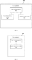
- FIG. 6 shows a structure of user equipment 600, and the user equipment 600 includes:
- the user equipment 600 further includes: a second determining module 603, configured to determine a monitoring parameter based on the physical layer signaling or the MAC layer signaling, where the monitoring parameter is associated with at least one of a downlink control information (DCI) format of a PDCCH to be monitored by the user equipment, a control channel element (CCE) aggregation level of the to-be-monitored PDCCH, and a CCE aggregation level of the DCI format of the to-be-monitored PDCCH.
- DCI downlink control information
- CCE control channel element
- the DCI format includes at least one of the following:
- the CCE aggregation level includes at least one of the following: one CCE, two CCEs, four CCEs, eight CCEs, and sixteen CCEs.
- the monitoring parameter includes at least one of the following: a monitoring period, a monitoring offset, and a monitoring pattern within a slot, where the monitoring pattern within a slot is used to indicate one or more time-domain symbols in a CORESET for PDCCH monitoring in a slot.
- the user equipment further includes:
- FIG. 7 shows a structure of user equipment 700, and the user equipment 700 includes:
- the DCI format includes at least one of the following:
- the CCE aggregation level includes at least one of the following: one CCE, two CCEs, four CCEs, eight CCEs, and sixteen CCEs.
- the monitoring parameter includes at least one of the following: a monitoring period, a monitoring offset, and a monitoring pattern within a slot, where the monitoring pattern within a slot is used to indicate one or more time-domain symbols in a CORESET for PDCCH monitoring in a slot.
- the user equipment provided in this embodiment of the present disclosure may perform the foregoing method embodiment.
- An implementation principle and a technical effect of the user equipment are similar to those of the method embodiment, and details are not described again in this embodiment.
- An embodiment of the present disclosure further provides a network side device. Because a problem-solving principle of the network side device is similar to that of a method for monitoring a PDCCH in the embodiments of the present disclosure, reference may be made to implementation of the method for implementation of the network side device, and no repeated description is provided.
- FIG. 8 shows a structure of a network side device 800, and the network side device 800 includes: a first sending module 801, configured to send physical layer signaling or media access control (MAC) layer signaling to user equipment, where the physical layer signaling or the media access control (MAC) layer signaling is used by the user equipment to determine a first parameter related to a PDCCH monitoring behavior of a serving cell, and the first parameter includes at least one of the following:
- the DCI format includes at least one of the following:
- the CCE aggregation level includes at least one of the following: one CCE, two CCEs, four CCEs, eight CCEs, and sixteen CCEs.
- the monitoring parameter includes at least one of the following: a monitoring period, a monitoring offset, and a monitoring pattern within a slot, where the monitoring pattern within a slot is used to indicate one or more time-domain symbols in a CORESET for PDCCH monitoring in a slot.
- the network side device 800 further includes: a second sending module 802, configured to send RRC signaling to the user equipment, where the RRC signaling is used by the user equipment to determine a second parameter related to the PDCCH monitoring behavior of the serving cell, and the second parameter includes at least one of the following:
- FIG. 9 shows a structure of a network side device 900
- the network side device 900 includes: a third sending module 901, configured to send RRC signaling to user equipment, where the RRC signaling is used by the user equipment to determine a monitoring parameter, and the monitoring parameter is associated with at least one of a downlink control information (DCI) format of a PDCCH to be monitored by the user equipment, a control channel element (CCE) aggregation level of the to-be-monitored PDCCH, and a CCE aggregation level of the DCI format of the to-be-monitored PDCCH.
- DCI downlink control information
- CCE control channel element
- the DCI format includes at least one of the following:
- the CCE aggregation level includes at least one of the following: one CCE, two CCEs, four CCEs, eight CCEs, and sixteen CCEs.
- the monitoring parameter includes at least one of the following: a monitoring period, a monitoring offset, and a monitoring pattern within a slot, where the monitoring pattern within a slot is used to indicate one or more time-domain symbols in a CORESET for PDCCH monitoring in a slot.
- the network side device provided in this embodiment of the present disclosure may perform the foregoing method embodiment.
- An implementation principle and a technical effect of the network side device are similar to those of the method embodiment, and details are not described again in this embodiment.
- user equipment 1000 shown in FIG. 10 includes: at least one processor 1001, a memory 1002, at least one network interface 1004, and a user interface 1003. All components of the user equipment 1000 are coupled by using the bus system 1005. It may be understood that the bus system 1005 is configured to implement a connection and communication between these components. In addition to a data bus, the bus system 1005 may include a power bus, a control bus, and a status signal bus. However, for clarity of description, various buses are marked as the bus system 1005 in FIG. 10 .
- the user interface 1003 may include a display, a keyboard, or a clicking device, for example, a mouse, a trackball, a touch panel, or a touchscreen.
- the memory 1002 in this embodiment of the present disclosure may be a volatile memory or a nonvolatile memory, or may include both a volatile memory and a nonvolatile memory.
- the nonvolatile memory may be a read-only memory (Read-Only Memory, ROM), a programmable read-only memory (Programmable ROM, PROM), an erasable programmable read-only memory (Erasable PROM, EPROM), an electrically erasable programmable read-only memory (Electrically EPROM, EEPROM), or a flash memory.
- the volatile memory may be a random access memory (Random Access Memory, RAM), used as an external cache.
- RAMs may be used, for example, a static random access memory (Static RAM, SRAM), a dynamic random access memory (Dynamic RAM, DRAM), a synchronous dynamic random access memory (Synchronous DRAM, SDRAM), a double data rate synchronous dynamic random access memory (Double Data Rate SDRAM, DDR SDRAM), an enhanced synchronous dynamic random access memory (Enhanced SDRAM, ESDRAM), a synch link dynamic random access memory (Synch link DRAM, SLDRAM), and a direct rambus random access memory (Direct Rambus RAM, DRRAM).
- Static RAM, SRAM static random access memory
- DRAM dynamic random access memory
- DRAM synchronous dynamic random access memory
- SDRAM double data rate synchronous dynamic random access memory
- Enhanced SDRAM, ESDRAM enhanced synchronous dynamic random access memory
- Synch link DRAM, SLDRAM synch link dynamic random access memory
- Direct Rambus RAM Direct Rambus RAM
- the memory 1002 stores the following element: an executable module or a data structure, a subset of an executable module or a data structure, or an extended set of an executable module or a data structure: an operating system 10021 and an application program 10022.
- the operating system 10021 includes various system programs, for example, a framework layer, a kernel library layer, and a driver layer, and is configured to implement various basic services and process hardware-based tasks.
- the application program 10022 includes various application programs, for example, a media player (Media Player), and a browser (Browser), and is configured to implement various application services.
- a program for implementing the method in the embodiments of the present disclosure may be included in the application program 10022.
- a program or an instruction stored in the memory 1002 when a program or an instruction stored in the memory 1002 is invoked, that is, when a program or an instruction stored in the application program 10022 is executed, the following steps are implemented: receiving physical layer signaling or media access control (MAC) layer signaling sent by a network side; and determining, based on the physical layer signaling or the MAC layer signaling, a first parameter related to a PDCCH monitoring behavior of a serving cell, where the first parameter includes at least one of the following: a control resource set (CORESET) of a to-be-monitored PDCCH; a search space of the to-be-monitored PDCCH; a DCI format in the search space of the to-be-monitored PDCCH; a CCE aggregation level in the search space of the to-be-monitored PDCCH; and an association relationship between the search space of the to-be-monitored PDCCH and the CORESET of the to-be-monitored PDCCH
- the following step may be further implemented: determining a monitoring parameter based on the physical layer signaling or the MAC layer signaling, where the monitoring parameter is associated with at least one of a downlink control information (DCI) format of a PDCCH to be monitored by the user equipment, a control channel element (CCE) aggregation level of the to-be-monitored PDCCH, and a CCE aggregation level of the DCI format of the to-be-monitored PDCCH.
- DCI downlink control information
- CCE control channel element
- a program or an instruction stored in the memory 1002 when a program or an instruction stored in the memory 1002 is invoked, that is, when a program or an instruction stored in the application program 10022 is executed, the following steps are implemented: receiving RRC signaling sent by a network side; and determining a monitoring parameter based on the RRC signaling, where the monitoring parameter is associated with at least one of a downlink control information (DCI) format of a PDCCH to be monitored by the user equipment, a control channel element (CCE) aggregation level of the to-be-monitored PDCCH, and a CCE aggregation level of the DCI format of the to-be-monitored PDCCH.
- DCI downlink control information
- CCE control channel element
- the user equipment provided in this embodiment of the present disclosure may perform the foregoing method embodiment.
- An implementation principle and a technical effect of the user equipment are similar to those of the method embodiment, and details are not described again in this embodiment.
- an embodiment of the present disclosure provides another network side device 1100, including: a processor 1101, a transceiver 1102, a memory 1103, a user interface 1104, and a bus interface.
- the processor 1101 may be responsible for managing the bus architecture and general processing.
- the memory 1103 may store data used by the processor 1101 when the processor 1101 performs an operation.
- the network side device 1100 may further include a computer program that is stored in the memory 1103 and configured to run on the processor 1101, where the computer program, when executed by the processor 1101, implements the following step: sending physical layer signaling or media access control (MAC) layer signaling to user equipment, where the physical layer signaling or the media access control (MAC) layer signaling is used by the user equipment to determine a first parameter related to a PDCCH monitoring behavior of a serving cell, and the first parameter includes at least one of the following: a control resource set (CORESET) of a to-be-monitored PDCCH; a search space of the to-be-monitored PDCCH; a DCI format in the search space of the to-be-monitored PDCCH; a CCE aggregation level in the search space of the to-be-monitored PDCCH; and an association relationship between the search space of the to-be-monitored PDCCH and the CORESET of the to-be-monitored P
- the following step may be further implemented: sending RRC signaling to the user equipment, where the RRC signaling is used by the user equipment to determine a parameter related to the PDCCH monitoring behavior of the serving cell, and the parameter includes at least one of the following: the control resource set (CORESET) of the to-be-monitored PDCCH; the search space of the to-be-monitored PDCCH; the DCI format in the search space of the to-be-monitored PDCCH; the CCE aggregation level in the search space of the to-be-monitored PDCCH; and the association relationship between the search space of the to-be-monitored PDCCH and the CORESET of the to-be-monitored PDCCH.
- CORESET control resource set
- the network side device 1100 may further include: a computer program that is stored in the memory 1103 and configured to run on the processor 1101, where the computer program, when executed by the processor 1101, implements the following step: sending RRC signaling to user equipment, where the RRC signaling is used by the user equipment to determine a monitoring parameter, and the monitoring parameter is associated with at least one of a downlink control information (DCI) format of a PDCCH to be monitored by the user equipment, a control channel element (CCE) aggregation level of the to-be-monitored PDCCH, and a CCE aggregation level of the DCI format of the to-be-monitored PDCCH.
- DCI downlink control information
- CCE control channel element
- a bus architecture may include any quantity of interconnected buses and bridges. Specifically, various circuits of one or more processors represented by the processor 1101 and a memory represented by the memory 1103 are interconnected. The bus architecture may further link various other circuits such as a peripheral device, a voltage regulator, and a power management circuit. These are well known in the art, and therefore are not further described in the embodiments of the present disclosure.
- a bus interface provides an interface.
- the transceiver 1102 may be a plurality of components. To be specific, the transceiver 1102 includes a transmitter and a receiver, and provides a unit configured to communicate with various other apparatuses on a transmission medium.
- Method or algorithm steps described in combination with the content disclosed in the present disclosure may be implemented by hardware, or may be implemented by a processor by executing a software instruction.
- the software instruction may be formed by a corresponding software module.
- the software module may be stored in a RAM, a flash memory, a ROM, an EPROM, an EEPROM, a register, a hard disk, a removable hard disk, a read-only compact disc, or a storage medium of any other form known in the art.
- a storage medium is coupled to the processor, so that the processor can read information from the storage medium or write information into the storage medium.
- the storage medium may be a component of the processor.
- the processor and the storage medium may be located in the ASIC.
- the ASIC may be located in a core network interface device.
- the processor and the storage medium may exist in the core network interface device as discrete components.
- the computer readable medium includes a computer storage medium and a communications medium, where the communications medium includes any medium that enables a computer program to be transmitted from one place to another.
- the storage medium may be any available medium accessible to a general-purpose or dedicated computer.
- the embodiments of the present disclosure may be provided as a method, a system, or a computer program product. Therefore, the embodiments of the present disclosure may use a form of hardware only embodiments, software only embodiments, or embodiments with a combination of software and hardware. Moreover, the embodiments of the present disclosure may use a form of a computer program product that is implemented on one or more computer-usable storage media (including but not limited to a magnetic disk memory, a CD-ROM, an optical memory, and the like) that include computer-usable program code.
- computer-usable storage media including but not limited to a magnetic disk memory, a CD-ROM, an optical memory, and the like
- These computer program instructions may be provided for a general-purpose computer, a dedicated computer, an embedded processor, or a processor of any other programmable data processing device to generate a machine, so that the instructions executed by a computer or a processor of any other programmable data processing device generate an apparatus for implementing a specific function in one or more processes in the flowcharts and/or in one or more blocks in the block diagrams.
- These computer program instructions may be alternatively stored in a computer readable memory that can instruct a computer or another programmable data processing device to work in a specific manner, so that the instructions stored in the computer readable memory generate an artifact that includes an instruction apparatus.
- the instruction apparatus implements a specific function in one or more processes in the flowcharts and/or in one or more blocks in the block diagrams.
- These computer program instructions may be alternatively loaded onto a computer or another programmable data processing device, so that a series of operations and steps are performed on the computer or the another programmable device, thereby generating computer-implemented processing. Therefore, the instructions executed on the computer or the another programmable device provide steps for implementing a specific function in one or more processes in the flowcharts and/or in one or more blocks in the block diagrams.
Landscapes
- Engineering & Computer Science (AREA)
- Signal Processing (AREA)
- Computer Networks & Wireless Communication (AREA)
- Mobile Radio Communication Systems (AREA)
Applications Claiming Priority (2)
| Application Number | Priority Date | Filing Date | Title |
|---|---|---|---|
| CN201810265749.7A CN110324883B (zh) | 2018-03-28 | 2018-03-28 | 配置物理下行控制信道的方法、用户设备和网络侧设备 |
| PCT/CN2019/077790 WO2019184696A1 (fr) | 2018-03-28 | 2019-03-12 | Procédé de configuration de canal de commande de liaison descendante physique, équipement utilisateur et dispositif côté réseau |
Publications (3)
| Publication Number | Publication Date |
|---|---|
| EP3780762A1 true EP3780762A1 (fr) | 2021-02-17 |
| EP3780762A4 EP3780762A4 (fr) | 2021-04-07 |
| EP3780762B1 EP3780762B1 (fr) | 2024-10-16 |
Family
ID=68060896
Family Applications (1)
| Application Number | Title | Priority Date | Filing Date |
|---|---|---|---|
| EP19776447.5A Active EP3780762B1 (fr) | 2018-03-28 | 2019-03-12 | Procédé de configuration de canal de commande de liaison descendante physique, équipement utilisateur et dispositif côté réseau |
Country Status (5)
| Country | Link |
|---|---|
| US (1) | US11937250B2 (fr) |
| EP (1) | EP3780762B1 (fr) |
| CN (1) | CN110324883B (fr) |
| ES (1) | ES2993021T3 (fr) |
| WO (1) | WO2019184696A1 (fr) |
Families Citing this family (5)
| Publication number | Priority date | Publication date | Assignee | Title |
|---|---|---|---|---|
| CN112788625B (zh) * | 2019-11-08 | 2024-04-19 | 联发科技股份有限公司 | 用于动态控制信号监测的方法及装置 |
| EP4072213A4 (fr) * | 2019-12-30 | 2022-12-07 | Huawei Technologies Co., Ltd. | Procédé et appareil de communication |
| WO2021098052A1 (fr) * | 2020-02-14 | 2021-05-27 | Zte Corporation | Procédés de surveillance de canal de commande |
| CN113300789B (zh) * | 2020-02-21 | 2022-09-23 | 大唐移动通信设备有限公司 | 信道监听及其控制方法及装置 |
| KR102951180B1 (ko) | 2020-03-26 | 2026-04-09 | 광동 오포 모바일 텔레커뮤니케이션즈 코포레이션 리미티드 | 물리적 채널 모니터링 방법 및 단말 기기 |
Family Cites Families (29)
| Publication number | Priority date | Publication date | Assignee | Title |
|---|---|---|---|---|
| CN101998429A (zh) * | 2009-08-13 | 2011-03-30 | 大唐移动通信设备有限公司 | 载波聚合系统中cce聚合长度指示方法、获取方法和设备 |
| CN102036346B (zh) * | 2009-09-30 | 2015-06-03 | 中兴通讯股份有限公司 | 一种调度信息传输的方法及系统 |
| CN102244885B (zh) * | 2010-05-10 | 2015-03-11 | 中国移动通信集团公司 | 一种控制信道盲检测方法及其装置 |
| CN102469048B (zh) * | 2010-11-18 | 2015-04-01 | 中兴通讯股份有限公司 | 一种确定下行控制信道搜索空间的方法及系统 |
| US8879667B2 (en) * | 2011-07-01 | 2014-11-04 | Intel Corporation | Layer shifting in open loop multiple-input, multiple-output communications |
| CN102891728B (zh) * | 2011-07-20 | 2016-06-08 | 华为技术有限公司 | 一种物理下行控制信道发送和盲检测方法、设备 |
| CN106059738B (zh) * | 2012-05-10 | 2019-11-26 | 华为终端有限公司 | 在增强型物理下行控制信道上传输信息的方法及设备 |
| CN103686772A (zh) * | 2012-09-20 | 2014-03-26 | 中兴通讯股份有限公司 | 增强型下行控制信道的配置、检测方法及装置、基站、终端 |
| CN103906244B (zh) * | 2012-12-28 | 2017-09-29 | 电信科学技术研究院 | 一种信息传输的方法、系统和设备 |
| WO2014107088A1 (fr) * | 2013-01-07 | 2014-07-10 | 엘지전자 주식회사 | Procédé et appareil d'émission/réception de signaux |
| US20160295597A1 (en) | 2013-07-26 | 2016-10-06 | Intel IP Corporation | Signaling interference information for user equipment assistance |
| CN103716823B (zh) * | 2013-12-23 | 2017-06-27 | 上海无线通信研究中心 | Lte/lte‑a系统中下行控制信息盲检指示发送及下行控制信息盲检方法 |
| CN104936206A (zh) * | 2014-03-20 | 2015-09-23 | 中兴通讯股份有限公司 | 控制信道的配置、检测方法、装置及系统 |
| WO2016072220A1 (fr) * | 2014-11-06 | 2016-05-12 | 株式会社Nttドコモ | Terminal d'utilisateur, station de base sans fil, et procédé de communications sans fil |
| CN106301671B (zh) * | 2015-05-15 | 2021-01-22 | 中兴通讯股份有限公司 | 下行控制信道的传输方法、配置方法及终端、基站 |
| CN106559161B (zh) | 2015-09-24 | 2019-01-04 | 株式会社Kt | 传输和接收下行控制信息的方法及其装置 |
| WO2017065666A1 (fr) * | 2015-10-13 | 2017-04-20 | Telefonaktiebolaget Lm Ericsson (Publ) | Modifications d'espace de recherche dynamique |
| CN107404365B (zh) | 2016-05-20 | 2022-08-19 | 中兴通讯股份有限公司 | 发送和接收控制信息的方法及装置 |
| CN106454901A (zh) | 2016-11-04 | 2017-02-22 | 维沃移动通信有限公司 | 下行控制信道的检测方法、指示方法、终端及网络侧设备 |
| EP3566381B1 (fr) * | 2017-02-06 | 2022-06-08 | Samsung Electronics Co., Ltd. | Structures et formats de transmission pour canaux de commande de liaison descendante |
| JP6861891B2 (ja) * | 2017-09-11 | 2021-04-21 | エルジー エレクトロニクス インコーポレイティド | 無線通信システムにおけるダウンリンク制御情報を送信する方法及び装置 |
| JP7079583B2 (ja) * | 2017-09-15 | 2022-06-02 | シャープ株式会社 | 端末装置、および、通信方法 |
| JP7007399B2 (ja) * | 2017-11-16 | 2022-01-24 | 株式会社Nttドコモ | 端末、無線通信方法、基地局及びシステム |
| US10638507B2 (en) * | 2017-11-16 | 2020-04-28 | Sharp Kabushiki Kaisha | User equipments, base stations and methods |
| US20190158205A1 (en) * | 2017-11-17 | 2019-05-23 | Sharp Laboratories Of America, Inc. | User equipments, base stations and methods |
| US10826758B2 (en) * | 2018-02-14 | 2020-11-03 | Asustek Computer Inc. | Method and apparatus for control resource monitoring considering beam failure recovery in a wireless communication system |
| US11297674B2 (en) * | 2018-02-14 | 2022-04-05 | Samsung Electronics Co., Ltd. | Method and apparatus for power savings at a user equipment |
| US20190254073A1 (en) * | 2018-02-15 | 2019-08-15 | Sharp Laboratories Of America, Inc. | User equipments, base stations and methods |
| JP2019169918A (ja) * | 2018-03-26 | 2019-10-03 | シャープ株式会社 | 端末装置、基地局装置、および、通信方法 |
-
2018
- 2018-03-28 CN CN201810265749.7A patent/CN110324883B/zh active Active
-
2019
- 2019-03-12 EP EP19776447.5A patent/EP3780762B1/fr active Active
- 2019-03-12 ES ES19776447T patent/ES2993021T3/es active Active
- 2019-03-12 WO PCT/CN2019/077790 patent/WO2019184696A1/fr not_active Ceased
-
2020
- 2020-09-28 US US17/035,116 patent/US11937250B2/en active Active
Non-Patent Citations (3)
| Title |
|---|
| "6 Random access procedure", 14 November 2017 (2017-11-14), XP051368737, Retrieved from the Internet <URL:http://www.3gpp.org/ftp/tsg%5Fran/WG1%5FRL1/TSGR1%5F90b/Docs/> [retrieved on 20171114] * |
| See also references of WO2019184696A1 * |
| VIVO: "Remaining details on NR-PDCCH search space", vol. RAN WG1, no. Reno, USA; 20171127 - 20171201, 18 November 2017 (2017-11-18), XP051369524, Retrieved from the Internet <URL:http://www.3gpp.org/ftp/tsg%5Fran/WG1%5FRL1/TSGR1%5F91/Docs/> [retrieved on 20171118] * |
Also Published As
| Publication number | Publication date |
|---|---|
| WO2019184696A1 (fr) | 2019-10-03 |
| US20210014885A1 (en) | 2021-01-14 |
| CN110324883A (zh) | 2019-10-11 |
| EP3780762B1 (fr) | 2024-10-16 |
| US11937250B2 (en) | 2024-03-19 |
| EP3780762A4 (fr) | 2021-04-07 |
| ES2993021T3 (en) | 2024-12-20 |
| CN110324883B (zh) | 2021-04-27 |
Similar Documents
| Publication | Publication Date | Title |
|---|---|---|
| US11937250B2 (en) | Method for configuring physical downlink control channel, user equipment and network side device | |
| US12432747B2 (en) | Frequency domain resource assignment method and device | |
| US11665685B2 (en) | Method for data processing, user equipment, and network-side device | |
| US20220360364A1 (en) | Method for detecting pdcch and terminal | |
| JP7053883B2 (ja) | 物理下りリンク制御チャネルのモニタリング方法、ユーザ機器及びネットワーク側機器 | |
| EP3735068B1 (fr) | Procédés et dispositifs de configuration et de détection de canal de commande, programme, et support | |
| US11510141B2 (en) | Method, user equipment and network side device for monitoring physical downlink control channel | |
| CN109802789B (zh) | 传输公共控制信息的时频域资源的配置方法和设备 | |
| CN110831159B (zh) | 一种信息传输方法和装置 | |
| EP3198961B1 (fr) | Procédé et station de base pour planification d'équipement utilisateur, et procédé et équipement utilisateur pour transmission harq | |
| JP7018504B2 (ja) | マルチスロット伝送方法および機器 | |
| JP2022062253A (ja) | 伝送方向及び伝送チャネルの決定方法及び装置、コンピュータ記憶媒体 |
Legal Events
| Date | Code | Title | Description |
|---|---|---|---|
| STAA | Information on the status of an ep patent application or granted ep patent |
Free format text: STATUS: THE INTERNATIONAL PUBLICATION HAS BEEN MADE |
|
| PUAI | Public reference made under article 153(3) epc to a published international application that has entered the european phase |
Free format text: ORIGINAL CODE: 0009012 |
|
| STAA | Information on the status of an ep patent application or granted ep patent |
Free format text: STATUS: REQUEST FOR EXAMINATION WAS MADE |
|
| 17P | Request for examination filed |
Effective date: 20201014 |
|
| AK | Designated contracting states |
Kind code of ref document: A1 Designated state(s): AL AT BE BG CH CY CZ DE DK EE ES FI FR GB GR HR HU IE IS IT LI LT LU LV MC MK MT NL NO PL PT RO RS SE SI SK SM TR |
|
| AX | Request for extension of the european patent |
Extension state: BA ME |
|
| A4 | Supplementary search report drawn up and despatched |
Effective date: 20210309 |
|
| RIC1 | Information provided on ipc code assigned before grant |
Ipc: H04L 5/00 20060101ALI20210302BHEP Ipc: H04W 52/02 20090101AFI20210302BHEP |
|
| DAV | Request for validation of the european patent (deleted) | ||
| DAX | Request for extension of the european patent (deleted) | ||
| GRAP | Despatch of communication of intention to grant a patent |
Free format text: ORIGINAL CODE: EPIDOSNIGR1 |
|
| STAA | Information on the status of an ep patent application or granted ep patent |
Free format text: STATUS: GRANT OF PATENT IS INTENDED |
|
| INTG | Intention to grant announced |
Effective date: 20240517 |
|
| GRAS | Grant fee paid |
Free format text: ORIGINAL CODE: EPIDOSNIGR3 |
|
| GRAA | (expected) grant |
Free format text: ORIGINAL CODE: 0009210 |
|
| STAA | Information on the status of an ep patent application or granted ep patent |
Free format text: STATUS: THE PATENT HAS BEEN GRANTED |
|
| AK | Designated contracting states |
Kind code of ref document: B1 Designated state(s): AL AT BE BG CH CY CZ DE DK EE ES FI FR GB GR HR HU IE IS IT LI LT LU LV MC MK MT NL NO PL PT RO RS SE SI SK SM TR |
|
| REG | Reference to a national code |
Ref country code: GB Ref legal event code: FG4D |
|
| REG | Reference to a national code |
Ref country code: CH Ref legal event code: EP |
|
| REG | Reference to a national code |
Ref country code: IE Ref legal event code: FG4D |
|
| REG | Reference to a national code |
Ref country code: DE Ref legal event code: R096 Ref document number: 602019060526 Country of ref document: DE |
|
| REG | Reference to a national code |
Ref country code: NL Ref legal event code: FP |
|
| REG | Reference to a national code |
Ref country code: ES Ref legal event code: FG2A Ref document number: 2993021 Country of ref document: ES Kind code of ref document: T3 Effective date: 20241220 |
|
| REG | Reference to a national code |
Ref country code: LT Ref legal event code: MG9D |
|
| REG | Reference to a national code |
Ref country code: AT Ref legal event code: MK05 Ref document number: 1733933 Country of ref document: AT Kind code of ref document: T Effective date: 20241016 |
|
| PG25 | Lapsed in a contracting state [announced via postgrant information from national office to epo] |
Ref country code: PT Free format text: LAPSE BECAUSE OF FAILURE TO SUBMIT A TRANSLATION OF THE DESCRIPTION OR TO PAY THE FEE WITHIN THE PRESCRIBED TIME-LIMIT Effective date: 20250217 Ref country code: HR Free format text: LAPSE BECAUSE OF FAILURE TO SUBMIT A TRANSLATION OF THE DESCRIPTION OR TO PAY THE FEE WITHIN THE PRESCRIBED TIME-LIMIT Effective date: 20241016 Ref country code: IS Free format text: LAPSE BECAUSE OF FAILURE TO SUBMIT A TRANSLATION OF THE DESCRIPTION OR TO PAY THE FEE WITHIN THE PRESCRIBED TIME-LIMIT Effective date: 20250216 |
|
| PG25 | Lapsed in a contracting state [announced via postgrant information from national office to epo] |
Ref country code: FI Free format text: LAPSE BECAUSE OF FAILURE TO SUBMIT A TRANSLATION OF THE DESCRIPTION OR TO PAY THE FEE WITHIN THE PRESCRIBED TIME-LIMIT Effective date: 20241016 |
|
| PG25 | Lapsed in a contracting state [announced via postgrant information from national office to epo] |
Ref country code: BG Free format text: LAPSE BECAUSE OF FAILURE TO SUBMIT A TRANSLATION OF THE DESCRIPTION OR TO PAY THE FEE WITHIN THE PRESCRIBED TIME-LIMIT Effective date: 20241016 |
|
| PG25 | Lapsed in a contracting state [announced via postgrant information from national office to epo] |
Ref country code: NO Free format text: LAPSE BECAUSE OF FAILURE TO SUBMIT A TRANSLATION OF THE DESCRIPTION OR TO PAY THE FEE WITHIN THE PRESCRIBED TIME-LIMIT Effective date: 20250116 |
|
| PG25 | Lapsed in a contracting state [announced via postgrant information from national office to epo] |
Ref country code: GR Free format text: LAPSE BECAUSE OF FAILURE TO SUBMIT A TRANSLATION OF THE DESCRIPTION OR TO PAY THE FEE WITHIN THE PRESCRIBED TIME-LIMIT Effective date: 20250117 Ref country code: AT Free format text: LAPSE BECAUSE OF FAILURE TO SUBMIT A TRANSLATION OF THE DESCRIPTION OR TO PAY THE FEE WITHIN THE PRESCRIBED TIME-LIMIT Effective date: 20241016 Ref country code: LV Free format text: LAPSE BECAUSE OF FAILURE TO SUBMIT A TRANSLATION OF THE DESCRIPTION OR TO PAY THE FEE WITHIN THE PRESCRIBED TIME-LIMIT Effective date: 20241016 |
|
| PG25 | Lapsed in a contracting state [announced via postgrant information from national office to epo] |
Ref country code: PL Free format text: LAPSE BECAUSE OF FAILURE TO SUBMIT A TRANSLATION OF THE DESCRIPTION OR TO PAY THE FEE WITHIN THE PRESCRIBED TIME-LIMIT Effective date: 20241016 |
|
| PG25 | Lapsed in a contracting state [announced via postgrant information from national office to epo] |
Ref country code: RS Free format text: LAPSE BECAUSE OF FAILURE TO SUBMIT A TRANSLATION OF THE DESCRIPTION OR TO PAY THE FEE WITHIN THE PRESCRIBED TIME-LIMIT Effective date: 20250116 |
|
| PG25 | Lapsed in a contracting state [announced via postgrant information from national office to epo] |
Ref country code: SM Free format text: LAPSE BECAUSE OF FAILURE TO SUBMIT A TRANSLATION OF THE DESCRIPTION OR TO PAY THE FEE WITHIN THE PRESCRIBED TIME-LIMIT Effective date: 20241016 |
|
| PG25 | Lapsed in a contracting state [announced via postgrant information from national office to epo] |
Ref country code: DK Free format text: LAPSE BECAUSE OF FAILURE TO SUBMIT A TRANSLATION OF THE DESCRIPTION OR TO PAY THE FEE WITHIN THE PRESCRIBED TIME-LIMIT Effective date: 20241016 |
|
| PGFP | Annual fee paid to national office [announced via postgrant information from national office to epo] |
Ref country code: ES Payment date: 20250414 Year of fee payment: 7 |
|
| REG | Reference to a national code |
Ref country code: DE Ref legal event code: R097 Ref document number: 602019060526 Country of ref document: DE |
|
| PG25 | Lapsed in a contracting state [announced via postgrant information from national office to epo] |
Ref country code: EE Free format text: LAPSE BECAUSE OF FAILURE TO SUBMIT A TRANSLATION OF THE DESCRIPTION OR TO PAY THE FEE WITHIN THE PRESCRIBED TIME-LIMIT Effective date: 20241016 |
|
| PG25 | Lapsed in a contracting state [announced via postgrant information from national office to epo] |
Ref country code: RO Free format text: LAPSE BECAUSE OF FAILURE TO SUBMIT A TRANSLATION OF THE DESCRIPTION OR TO PAY THE FEE WITHIN THE PRESCRIBED TIME-LIMIT Effective date: 20241016 |
|
| PG25 | Lapsed in a contracting state [announced via postgrant information from national office to epo] |
Ref country code: SK Free format text: LAPSE BECAUSE OF FAILURE TO SUBMIT A TRANSLATION OF THE DESCRIPTION OR TO PAY THE FEE WITHIN THE PRESCRIBED TIME-LIMIT Effective date: 20241016 |
|
| PG25 | Lapsed in a contracting state [announced via postgrant information from national office to epo] |
Ref country code: CZ Free format text: LAPSE BECAUSE OF FAILURE TO SUBMIT A TRANSLATION OF THE DESCRIPTION OR TO PAY THE FEE WITHIN THE PRESCRIBED TIME-LIMIT Effective date: 20241016 |
|
| PG25 | Lapsed in a contracting state [announced via postgrant information from national office to epo] |
Ref country code: IT Free format text: LAPSE BECAUSE OF FAILURE TO SUBMIT A TRANSLATION OF THE DESCRIPTION OR TO PAY THE FEE WITHIN THE PRESCRIBED TIME-LIMIT Effective date: 20241016 |
|
| PLBE | No opposition filed within time limit |
Free format text: ORIGINAL CODE: 0009261 |
|
| STAA | Information on the status of an ep patent application or granted ep patent |
Free format text: STATUS: NO OPPOSITION FILED WITHIN TIME LIMIT |
|
| PG25 | Lapsed in a contracting state [announced via postgrant information from national office to epo] |
Ref country code: SE Free format text: LAPSE BECAUSE OF FAILURE TO SUBMIT A TRANSLATION OF THE DESCRIPTION OR TO PAY THE FEE WITHIN THE PRESCRIBED TIME-LIMIT Effective date: 20241016 |
|
| 26N | No opposition filed |
Effective date: 20250717 |
|
| PG25 | Lapsed in a contracting state [announced via postgrant information from national office to epo] |
Ref country code: MC Free format text: LAPSE BECAUSE OF FAILURE TO SUBMIT A TRANSLATION OF THE DESCRIPTION OR TO PAY THE FEE WITHIN THE PRESCRIBED TIME-LIMIT Effective date: 20241016 |
|
| REG | Reference to a national code |
Ref country code: CH Ref legal event code: H13 Free format text: ST27 STATUS EVENT CODE: U-0-0-H10-H13 (AS PROVIDED BY THE NATIONAL OFFICE) Effective date: 20251023 |
|
| PG25 | Lapsed in a contracting state [announced via postgrant information from national office to epo] |
Ref country code: LU Free format text: LAPSE BECAUSE OF NON-PAYMENT OF DUE FEES Effective date: 20250312 |
|
| REG | Reference to a national code |
Ref country code: BE Ref legal event code: MM Effective date: 20250331 |
|
| PG25 | Lapsed in a contracting state [announced via postgrant information from national office to epo] |
Ref country code: BE Free format text: LAPSE BECAUSE OF NON-PAYMENT OF DUE FEES Effective date: 20250331 |
|
| PG25 | Lapsed in a contracting state [announced via postgrant information from national office to epo] |
Ref country code: CH Free format text: LAPSE BECAUSE OF NON-PAYMENT OF DUE FEES Effective date: 20250331 |
|
| PG25 | Lapsed in a contracting state [announced via postgrant information from national office to epo] |
Ref country code: IE Free format text: LAPSE BECAUSE OF NON-PAYMENT OF DUE FEES Effective date: 20250312 |
|
| PGFP | Annual fee paid to national office [announced via postgrant information from national office to epo] |
Ref country code: NL Payment date: 20260213 Year of fee payment: 8 |
|
| PGFP | Annual fee paid to national office [announced via postgrant information from national office to epo] |
Ref country code: GB Payment date: 20260202 Year of fee payment: 8 |
|
| PGFP | Annual fee paid to national office [announced via postgrant information from national office to epo] |
Ref country code: DE Payment date: 20260128 Year of fee payment: 8 |
|
| PGFP | Annual fee paid to national office [announced via postgrant information from national office to epo] |
Ref country code: FR Payment date: 20260209 Year of fee payment: 8 |