EP3780767A1 - Procédé et appareil de réduction de la consommation d'énergie d'un terminal dans un système de communication sans fil - Google Patents
Procédé et appareil de réduction de la consommation d'énergie d'un terminal dans un système de communication sans fil Download PDFInfo
- Publication number
- EP3780767A1 EP3780767A1 EP19788011.5A EP19788011A EP3780767A1 EP 3780767 A1 EP3780767 A1 EP 3780767A1 EP 19788011 A EP19788011 A EP 19788011A EP 3780767 A1 EP3780767 A1 EP 3780767A1
- Authority
- EP
- European Patent Office
- Prior art keywords
- saving mode
- power saving
- terminal
- base station
- psr
- Prior art date
- Legal status (The legal status is an assumption and is not a legal conclusion. Google has not performed a legal analysis and makes no representation as to the accuracy of the status listed.)
- Pending
Links
Images








Classifications
-
- H—ELECTRICITY
- H04—ELECTRIC COMMUNICATION TECHNIQUE
- H04W—WIRELESS COMMUNICATION NETWORKS
- H04W52/00—Power management, e.g. Transmission Power Control [TPC] or power classes
- H04W52/02—Power saving arrangements
- H04W52/0209—Power saving arrangements in terminal devices
-
- H—ELECTRICITY
- H04—ELECTRIC COMMUNICATION TECHNIQUE
- H04W—WIRELESS COMMUNICATION NETWORKS
- H04W52/00—Power management, e.g. Transmission Power Control [TPC] or power classes
- H04W52/02—Power saving arrangements
- H04W52/0209—Power saving arrangements in terminal devices
- H04W52/0225—Power saving arrangements in terminal devices using monitoring of external events, e.g. the presence of a signal
- H04W52/0229—Power saving arrangements in terminal devices using monitoring of external events, e.g. the presence of a signal where the received signal is a wanted signal
- H04W52/0235—Power saving arrangements in terminal devices using monitoring of external events, e.g. the presence of a signal where the received signal is a wanted signal where the received signal is a power saving command
-
- H—ELECTRICITY
- H04—ELECTRIC COMMUNICATION TECHNIQUE
- H04W—WIRELESS COMMUNICATION NETWORKS
- H04W52/00—Power management, e.g. Transmission Power Control [TPC] or power classes
- H04W52/02—Power saving arrangements
- H04W52/0209—Power saving arrangements in terminal devices
- H04W52/0225—Power saving arrangements in terminal devices using monitoring of external events, e.g. the presence of a signal
- H04W52/0229—Power saving arrangements in terminal devices using monitoring of external events, e.g. the presence of a signal where the received signal is a wanted signal
-
- H—ELECTRICITY
- H04—ELECTRIC COMMUNICATION TECHNIQUE
- H04W—WIRELESS COMMUNICATION NETWORKS
- H04W52/00—Power management, e.g. Transmission Power Control [TPC] or power classes
- H04W52/02—Power saving arrangements
- H04W52/0209—Power saving arrangements in terminal devices
- H04W52/0251—Power saving arrangements in terminal devices using monitoring of local events, e.g. events related to user activity
-
- H—ELECTRICITY
- H04—ELECTRIC COMMUNICATION TECHNIQUE
- H04W—WIRELESS COMMUNICATION NETWORKS
- H04W52/00—Power management, e.g. Transmission Power Control [TPC] or power classes
- H04W52/02—Power saving arrangements
- H04W52/0209—Power saving arrangements in terminal devices
- H04W52/0261—Power saving arrangements in terminal devices managing power supply demand, e.g. depending on battery level
-
- H—ELECTRICITY
- H04—ELECTRIC COMMUNICATION TECHNIQUE
- H04W—WIRELESS COMMUNICATION NETWORKS
- H04W72/00—Local resource management
- H04W72/20—Control channels or signalling for resource management
- H04W72/23—Control channels or signalling for resource management in the downlink direction of a wireless link, i.e. towards a terminal
- H04W72/231—Control channels or signalling for resource management in the downlink direction of a wireless link, i.e. towards a terminal the control data signalling from the layers above the physical layer, e.g. RRC or MAC-CE signalling
-
- H—ELECTRICITY
- H04—ELECTRIC COMMUNICATION TECHNIQUE
- H04W—WIRELESS COMMUNICATION NETWORKS
- H04W8/00—Network data management
- H04W8/22—Processing or transfer of terminal data, e.g. status or physical capabilities
- H04W8/24—Transfer of terminal data
-
- Y—GENERAL TAGGING OF NEW TECHNOLOGICAL DEVELOPMENTS; GENERAL TAGGING OF CROSS-SECTIONAL TECHNOLOGIES SPANNING OVER SEVERAL SECTIONS OF THE IPC; TECHNICAL SUBJECTS COVERED BY FORMER USPC CROSS-REFERENCE ART COLLECTIONS [XRACs] AND DIGESTS
- Y02—TECHNOLOGIES OR APPLICATIONS FOR MITIGATION OR ADAPTATION AGAINST CLIMATE CHANGE
- Y02D—CLIMATE CHANGE MITIGATION TECHNOLOGIES IN INFORMATION AND COMMUNICATION TECHNOLOGIES [ICT], I.E. INFORMATION AND COMMUNICATION TECHNOLOGIES AIMING AT THE REDUCTION OF THEIR OWN ENERGY USE
- Y02D30/00—Reducing energy consumption in communication networks
- Y02D30/70—Reducing energy consumption in communication networks in wireless communication networks
Definitions
- the disclosure relates to a method and apparatus for reducing power consumption of a terminal in a wireless communication system.
- the 5G or pre-5G communication system is also called a beyond 4th-generation (4G) network communication system or post long term evolution (LTE) system.
- 4G millimeter wave
- GHz giga hertz
- an advanced coding modulation e.g., hybrid frequency-shift keying (FSK) and quadrature amplitude modulation (QAM) modulation(FQAM), sliding window superposition coding(SWSC), and an advanced access technology, e.g., filter bank multi carrier(FBMC), non-orthogonal multiple access(NOMA), sparse code multiple access(SCMA) are being developed.
- ACM advanced coding modulation
- FQAM quadrature amplitude modulation
- SWSC sliding window superposition coding
- FBMC filter bank multi carrier
- NOMA non-orthogonal multiple access
- SCMA sparse code multiple access
- IoT Internet of Things
- M2M Machine to Machine
- MTC Machine Type Communication
- IoT intelligent Internet Technology (IT) services that create new values for human life by collecting and analyzing data generated from connected things may be provided.
- IoT may be applied to a variety of areas, such as smart home, smart building, smart city, smart car or connected car, smart grid, health care, smart home appliances and advanced medical services through convergence and combination between existing Information Technologies (IT) and various industrial applications.
- Embodiments of the disclosure provide an apparatus and method for effectively providing a service in a mobile communication system.
- the disclosure relates to a method and apparatus for reducing power consumption of a terminal in a wireless communication system, and an operation method, performed by a terminal, for reducing power consumption of the terminal in a wireless communication system according to an embodiment of the disclosure includes transmitting a power saving mode request (PSR) message requesting a power saving mode to a base station and receiving configuration information or indicator information relating to the power saving mode from the base station.
- PSR power saving mode request
- services may be effectively provided in a mobile communication system.
- an operation method, performed by a terminal, for reducing power consumption of the terminal in a wireless communication system includes transmitting a power saving mode request (PSR) message requesting a power saving mode to a base station and receiving configuration information or indicator information relating to the power saving mode from the base station.
- PSR power saving mode request
- the PSR message may include at least one or more of a power saving mode request indicator, a maximum bandwidth for a bandwidth part, a minimum value of a physical downlink control channel (PDCCH) monitoring periodicity, a maximum value of a number of PDCCH candidates, and a maximum value of a number of layers.
- a power saving mode request indicator e.g., a power saving mode request indicator, a maximum bandwidth for a bandwidth part, a minimum value of a physical downlink control channel (PDCCH) monitoring periodicity, a maximum value of a number of PDCCH candidates, and a maximum value of a number of layers.
- PDCCH physical downlink control channel
- the transmitting of the PSR message requesting the power saving mode to the base station may include transmitting the PSR message to the base station through at least one or more signaling among higher layer signaling or L1 signaling.
- the L1 signaling may include at least one or more of a physical uplink control channel (PUCCH), a physical uplink shared channel (PUSCH), or a dedicated physical layer channel for transmitting the PSR message.
- a physical uplink control channel PUCCH
- PUSCH physical uplink shared channel
- dedicated physical layer channel for transmitting the PSR message.
- the receiving of the configuration information or the indicator information relating to the power saving mode from the base station may include receiving the configuration information relating to the power saving mode through higher layer signaling, and receiving the indicator information relating to the power saving mode through L1 signaling.
- the configuration information relating to the power saving mode may include at least one or more of a bandwidth part, a PDCCH monitoring periodicity, a number of PDCCH candidates, and a number of layers.
- the indicator information relating to the power saving mode may include at least one or more of a change in a bandwidth part and a change in a number of layers.
- the method may further include transmitting a power saving mode release request (PSR2) message requesting release of the power saving mode to the base station.
- PSR2 power saving mode release request
- an operation method, performed by a base station, for reducing power consumption of a terminal in a wireless communication system includes receiving a PSR message requesting a power saving mode from the terminal, and transmitting configuration information or indicator information relating to the power saving mode to the terminal in response to the PSR message.
- the PSR message may include at least one or more of a power saving mode request indicator, a maximum bandwidth for a bandwidth part, a minimum value of a PDCCH monitoring periodicity, a maximum value of a number of PDCCH candidates, and a maximum value of a number of layers.
- the receiving of the PSR message requesting the power saving mode from the terminal may include receiving the PSR message from the terminal through at least one or more signaling among higher layer signaling or L1 signaling.
- the L1 signaling may include at least one or more of a PUCCH, a PUSCH, and a dedicated physical layer channel for transmitting the PSR message.
- the transmitting of the configuration information or the indicator information relating to the power saving mode to the terminal in response to the PSR message may include transmitting the configuration information relating to the power saving mode through higher layer signaling, and transmitting the indicator information relating to the power saving mode through L1 signaling.
- the configuration information relating to the power saving mode may include at least one or more of a bandwidth part, a PDCCH monitoring periodicity, a number of PDCCH candidates, and a number of layers.
- the indicator information relating to the power saving mode may include at least one or more of a change in a bandwidth part and a change in a number of layers.
- the operation method may further include receiving a PSR2 message requesting release of the power saving mode from the terminal and freely operating parameters related to data transmission or reception, in response to the PSR2 message.
- a terminal for reducing power consumption in a wireless communication system includes a transceiver, at least one or more memories storing a program for reducing power consumption, and at least one or more processors configured to execute the program to control a PSR message requesting a power saving mode to be transmitted to a base station, and configuration information or indicator information relating to the power saving mode to be received from the base station.
- a base station for reducing power consumption of a terminal in a wireless communication system includes a transceiver, at least one or more memories storing a program for reducing power consumption, and at least one or more processors configured to execute the program to control a PSR message requesting a power saving mode to be received from the terminal, and configuration information or indicator information relating to the power saving mode to be transmitted to the terminal, in response to the PSR message.
- an operation method, performed by a terminal, for reducing power consumption of the terminal in a wireless communication system includes receiving configuration information about a maximum number of layers or a maximum number of DMRS ports for a PDSCH from a base station, and activating antennas based on the maximum number of layers or the maximum number of DMRS ports.
- the configuration information about the maximum number of layers or the maximum number of DMRS ports may be received through L1 signaling.
- an operation method, performed by a terminal, for reducing power consumption of the terminal in a wireless communication system includes receiving configuration information about a number of layers or a number of DMRS ports for a PDSCH from a base station, determining whether the number of layers or the number of DMRS ports is less than a preset threshold, determining whether a time gap between a starting time of the PDSCH and a time at which the PDCCH is received is greater than a transition time T gap required to change an extent of antenna activation when the number of layers or the number of DMRS ports is less than the preset threshold, and activating only some of antennas based on the configuration information after T gap when the time gap between the starting time of the PDSCH and the time at which the PDCCH is received is greater than the transition time T gap required to change the extent of antenna activation.
- the operation method may further include activating all of the antennas to receive the PDSCH when the number of layers or the number of DMRS ports is greater than the preset threshold.
- the operation method may further include activating all of the antennas to receive the PDSCH when the time gap between the starting time of the PDSCH and the time at which the PDCCH is received is less than the transition time T gap required to change the extent of antenna activation.
- each blocks and combination of the blocks of a flowchart may be performed by computer program instructions.
- the computer program instructions may be loaded on a processor of a universal computer, a special-purpose computer, or other programmable data processing equipment, and thus they generate means for performing functions described in the block(s) of the flowcharts when executed by the processor of the computer or other programmable data processing equipment.
- the computer program instructions may also be stored in computer-usable or computer-readable memories oriented for computers or other programmable data processing equipment, so it is possible to manufacture a product that contains instruction means for performing functions described in the block(s) of the flowchart.
- the computer program instructions may also be loaded on computers or programmable data processing equipment, so it is possible for the instructions to generate a process executed by the computer or the other programmable data processing equipment to provide steps for performing functions described in the block(s) of the flowchart.
- each block may represent a part of a module, segment, or code including one or more executable instructions to perform particular logic function(s). It is noted that the functions described in the blocks may occur out of order in some alternate embodiments of the disclosure. For example, two successive blocks may be performed substantially at the same time or in reverse order.
- module refers to a software or hardware component, such as field programmable gate array (FPGA) or application specific integrated circuit (ASIC), which performs some functions.
- the module is not limited to software or hardware.
- the module may be configured to be stored in an addressable storage medium, or to execute one or more processors.
- the modules may include components, such as software components, object-oriented software components, class components and task components, processes, functions, attributes, procedures, subroutines, segments of program codes, drivers, firmware, microcodes, circuits, data, databases, data structures, tables, arrays, and variables. Functions served by components and modules may be combined into a less number of components and modules, or further divided into a more number of components and modules.
- the components and modules may be implemented to execute one or more central processing units (CPUs) in a device or security multimedia card.
- the module may include one or more processors.
- Wireless communication systems are evolving from early systems that provide voice-oriented services to broadband wireless communication systems that provide high data rate and high quality packet data services such as 3GPP high speed packet access (HSPA), long term evolution (LTE) or evolved universal terrestrial radio access (E-UTRA), LTE-advanced (LTE-A), 3GPP2 high rate packet data (HRPD), ultra mobile broadband (UMB), and IEEE 820.16e communication standards.
- HSPA high speed packet access
- LTE long term evolution
- E-UTRA evolved universal terrestrial radio access
- LTE-advanced LTE-A
- 3GPP2 high rate packet data HRPD
- UMB ultra mobile broadband
- IEEE 820.16e communication standards IEEE 820.16e communication standards.
- a 5G or new radio (NR) communication system is required to freely reflect various requirements of users and service providers.
- NR new radio
- the services considered for the 5G or NR communication system may include enhanced Mobile Broadband (eMBB), massive Machine Type Communication (mMTC), Ultra Reliability Low Latency Communication (URLLC), etc.
- eMBB enhanced Mobile Broadband
- mMTC massive Machine Type Communication
- URLLC Ultra Reliability Low Latency Communication
- the eMBB is aimed at providing more enhanced data rates than the existing LTE, LTE-A or LTE-Pro system may support.
- the eMBB is required to provide 20 Gbps peak data rate in DL and 10 Gbps peak data rate in UL in light of a single base station.
- the 5G or NR communication system needs to provide increasing user perceived data rate while providing the peak data rate.
- enhancement of various technologies for transmission or reception including multiple-input multiple-output (MIMO) transmission technologies is required.
- MIMO multiple-input multiple-output
- the 5G or NR communication system may use frequency bandwidth wider than 20 MHz in the 3 to 6 GHz band or in the 6 GHz or higher band, thereby satisfying the data rate required by the 5G or NR communication system.
- mMTC is considered to support an application service such as Internet of Things (loT).
- LoT Internet of Things
- the loT is equipped in various sensors and devices to provide communication functions, it may be supposed to support a large number of terminals in a cell (e.g., 1,000,000 terminals/km 2 ).
- a terminal supporting the mMTC is more likely to be located in a shadow area, such as underground of a building, which might not be covered by a cell by the nature of the service, so the mMTC requires an even larger coverage than expected for other services provided by the 5G or NR communication system.
- the terminal supporting the mMTC needs to be a low-cost terminal, and requires quite long battery life time such as 10 to 15 years because the battery in the terminal is hard to be changed frequently.
- URLLC is a mission critical cellular-based wireless communication service.
- the URLLC may provide services used for remote control over robots or machinery, industrial automation, unmanned aerial vehicle, remote health care, emergency alert, etc.
- communication offered by the URLLC requires very low latency and very high reliability.
- URLCC services need to satisfy sub-millisecond (less than 0.5 millisecond) air interface latency and simultaneously require error rates lower than 1 packet loss in 10 -5 packets.
- the 5G or NR system needs to provide a smaller transmit time interval (TTI) than for other services, and simultaneously requires a design that allocates a wide range of resources for a frequency band to secure reliability of the communication link.
- TTI transmit time interval
- Those three services in the 5G or NR communication system, eMBB, URLLC, and mMTC may be multiplexed in a single system for transmission.
- different transmission or reception schemes and parameters may be used between the services.
- Embodiments of the disclosure will be described in conjunction with accompanying drawings. Although the following embodiments of the disclosure will focus on the 5G or NR system as an example, they may be equally applied to other communication systems with similar technical backgrounds or channel types. For example, they may be applied to LTE or LTE-A mobile communication and future mobile communication technologies beyond 5G. Furthermore, embodiments of the disclosure will also be applied to other communication systems through some modifications to an extent that does not significantly deviate from the scope of the disclosure when judged by those of ordinary skill in the art.
- terminals that are going to perform low-power communication may request a power saving mode directly from a base station.
- the base station may perform wake-up signal configuration, bandwidth part configuration having narrow bandwidth, long monitoring periodicity configuration for downlink control channel, single layer transmission configuration for the corresponding terminal, etc. Accordingly, the terminal is able to communicate with the base station in the power saving mode.
- the base station may configure the maximum number of transmission layers for the terminal.
- the terminal may expect that no layer beyond the maximum number of transmission layers would not be transmitted, and may operate a number of transmit or receive antenna ports equal to or less than the maximum number of transmission layers.
- the terminal may report back to the base station and update a capability for the number of layers that the terminal is able to support.
- the terminal may activate only some of antennas based on downlink control information received on a downlink control channel.
- FIG. 1 illustrates a basic structure of the time-frequency domain, which is a radio resource region of a 5G or NR system.
- the horizontal axis represents the time domain
- the vertical axis represents the frequency domain
- a basic resource unit in the time and frequency domain is a resource element (RE) 101, which may be defined as an Orthogonal Frequency Division Multiplexing (OFDM) symbol 102 on the time axis and a subcarrier 103 on the frequency axis.
- OFDM Orthogonal Frequency Division Multiplexing
- NscRB e.g., 12
- successive REs may constitute a single resource block (RB) 104.
- FIG. 2 illustrates a frame, subframe, and slot structures in a 5G or NR system.
- the one frame 200 may be defined to have a length of 10 ms.
- the one subframe 201 may be defined to have a length of 1 ms, and thus a total of 10 subframes 201 may constitute the 1 frame 200.
- the one slot 202 or 203 may be defined to have 14 OFDM symbols (i.e., the number of symbols per 1 slot N symb slot is 14).
- the one subframe 201 may include one or more slots 202 and 203, and the number of slots 202 and 203 per 1 subframe may vary depending on subcarrier spacing configuration values ⁇ 204 and 205.
- N slot subframe , ⁇ and N slot frame , ⁇ depending on the subcarrier spacing setting value ⁇ may be defined as in the following Table 1. [Table 1] ⁇ N symb slot N slot frame , ⁇ N slot subframe , ⁇ 0 14 10 1 1 14 20 2 2 14 40 4 3 14 80 8 4 14 160 16 5 14 320 32
- DCI downlink control information
- scheduling information for uplink data (or physical uplink shared channel (PUSCH)) or downlink data (or physical downlink shared channel (PDSCH)) is transmitted from the base station to the terminal in the DCI.
- the terminal may monitor a fallback DCI format and a non-fallback DCI format for PUSCH or PDSCH.
- the fallback DCI format may include a fixed field predefined between the base station and the terminal, and the non-fallback DCI format may include a configurable field.
- the DCI may be transmitted on the physical downlink control channel (PDCCH) after going through channel coding and modulation processes.
- Cyclic redundancy check (CRC) may be appended to a DCI message payload, and the CRC may be scrambled by a radio network temporary identifier (RNTI) that corresponds to identity of the terminal (or UE).
- RNTI radio network temporary identifier
- RNTI radio network temporary identifier
- the RNTI is transmitted not explicitly but in a CRC calculation process.
- the UE On reception of the DCI message transmitted on the PDCCH, the UE may check CRC with an allocated RNTI, and determine that the DCI message is transmitted to the UE when the CRC check result is correct.
- DCI that schedules a PDSCH for system information may be scrambled by an SI-RNTI.
- DCI that schedules a PDSCH for a random access response (RAR) message may be scrambled by an RA-RNTI.
- DCI that schedules a PDSCH for a paging message may be scrambled by a P-RNTI.
- DCI that notifies a slot format indicator (SFI) may be scrambled by an SFI-RNTI.
- DCI that notifies a transmit power control (TPC) may be scrambled by a TPC-RNTI.
- DCI that schedules UE-specific PDSCH or PUSCH may be scrambled by a Cell RNTI (C-RNTI).
- C-RNTI Cell RNTI
- DCI format 0_0 may be used for the fallback DCI that schedules the PUSCH, in which case the CRC may be scrambled by a C-RNTI.
- the DCI format 0_0 with the CRC scrambled by C-RNTI may include e.g., the following information.
- DCI format 0_1 may be used for the non-fallback DCI that schedules the PUSCH, in which case the CRC may be scrambled by a C-RNTI.
- the DCI format 0_1 with the CRC scrambled by the C-RNTI may include e.g., the following information.
- DCI format 1_0 may be used for the fallback DCI that schedules the PDSCH, in which case the CRC may be scrambled by a C-RNTI.
- the DCI format 1_0 with the CRC scrambled by the C-RNTI may include e.g., the following information.
- DCI format 1_1 may be used for the non-fallback DCI that schedules the PDSCH, in which case the CRC may be scrambled by a C-RNTI.
- the DCI format 1_1 with the CRC scrambled by the C-RNTI may include e.g., the following information.
- FIG. 3 is a diagram for describing configuration of bandwidth parts in a 5G or NR system.
- UE bandwidth 300 is configured with two bandwidth part (BWPs), BWP#1 301 and BWP#2 302.
- a base station may configure the UE with one or more BWPs, and set the following information for each BWP.
- various parameters related to the BWP may be configured for the UE.
- These pieces of configuration information may be transmitted by the base station to the UE through higher layer signaling, e.g., RRC signaling.
- RRC signaling e.g., RRC signaling.
- At least one of the configured one or more BWPs may be activated. Whether to activate the configured BWP may be notified by the base station to the UE semi-statically through RRC signaling or dynamically through an MAC CE or DCI.
- Configuration of the BWP supported by the 5G or NR system may be used for various purposes.
- the UE when the bandwidth supported by the UE is less than the system bandwidth, the UE may be supported through BWP configuration.
- BWP configuration For example, in Table 6, a frequency location of the BWP (configuration information 2) is configured for the UE, thereby allowing the UE to transmit or receive data at a particular frequency location in the system bandwidth.
- the base station may configure multiple BWPs for the UE. For example, to support data transmission and reception using both a subcarrier spacing of 15 KHz and a subcarrier spacing of 30 KHz for a UE, two BWPs may be configured with subcarrier spacing of 15 KHz and 30 KHz, respectively.
- the different BWPs may be frequency division multiplexed, and for data transmission and reception with particular subcarrier spacing, a BWP configured with the subcarrier spacing may be activated.
- the BS may configure BWPs with different sizes of bandwidth for the UE. For example, when the UE supports very large bandwidth, e.g., 100 MHz bandwidth, and always transmits or receives data in the bandwidth, the UE may consume very large power. In a situation where there is no traffic in particular, monitoring unnecessary downlink control channel in the large 100 MHz bandwidth is very inefficient in terms of power consumption.
- the base station may configure a BWP with relatively small bandwidth, e.g., a 20 MHz BWP, for the UE. In the situation that there is no traffic, the UE may perform monitoring in the 20 MHz BWP, and when data occurs, the UE may transmit or receive the data in an 100 MHz BWP under instructions from the base station.
- UEs may receive configuration information for an initial BWP in a master information block (MIB) in an initial access process before being RRC connected.
- the UE may be configured with a control resource set (CORESET) for a downlink control channel on which DCI may be transmitted to schedule a system information block (SIB) from the MIB of a physical broadcast channel (PBCH).
- CORESET control resource set
- SIB system information block
- PBCH physical broadcast channel
- Bandwidth of the control resource set configured in the MIB may be regarded as the initial BWP, and the UE may receive a PDSCH on which the SIB is transmitted in the initial BWP.
- the initial BWP may also be used for other system information (OSI), paging, or random access apart from reception of the SIB.
- OSI system information
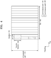
- FIG. 4 is a diagram for describing configuration of control resource sets of a downlink control channel in a 5G or NR system.
- control resource sets in which a downlink control channel is transmitted in the 5G or NR communication system is shown.
- a BWP 410 of a UE on the frequency axis and two control resource sets (CORESET #1 401 and CORESET #2 402) in a slot 420 on the time axis are configured.
- the control resource sets 401 and 402 may be configured in a particular frequency resource 403 in the entire UE BWP 410 on the frequency axis.
- One or more OFDM symbols may be configured on the time axis, and defined as control resource set duration 404.
- CORESET #1 401 is configured to have the control resource set duration of two symbols
- CORESET #2 402 is configured to have the control resource set duration of one symbol.
- the control resource set may be configured by the base station for the UE through higher layer signaling, e.g., system information (SI), master information block (MIB), or radio resource control (RRC) signaling.
- SI system information
- MIB master information block
- RRC radio resource control
- Configuring the UE with the control resource set refers to providing the UE with information such as control resource set identity, a frequency location of the control resource set, length of symbols of the control resource set, etc.
- the control resource set configuration information may include the following information:
- FIG. 5 illustrates a structure of a downlink control channel in a 5G or NR system.
- a basic unit of time and frequency resource that forms a control channel is referred to as a resource element group (REG) 503, and the REG 503 may be defined by one OFDM symbol 501 on the time axis and one physical resource block (PRB) 502, i.e., 12 subcarriers on the frequency axis.
- REGs 503 may be successively arranged into a downlink control channel allocation unit.
- the one CCE 504 may be comprised of a plurality of REGs 503.
- the REG 503 may include 12 REs
- the one CCE 504 may include 72 REs.
- the downlink control resource set may include multiple CCEs 504, and a particular downlink control channel may be transmitted by being mapped to one or more CCEs 504 based on an aggregation level (AL) in the control resource set.
- the CCEs 504 in the control resource set may be distinguished by numbers, in which case, the numbers may be given in a logical mapping method.
- the basic unit of the downlink control channel as shown in FIG. 5 i.e., the REG 503, may include both REs to which DCI is mapped and a region to which a DMRS 505 that is a reference signal for decoding them is mapped. As shown in FIG. 5 , three DMRSs 505 may be transmitted in one REG 503.
- the number of CCEs required to transmit a PDCCH may be 1, 2, 4, 8, or 16 depending on the aggregation level (AL), and a different number of CCEs may be used to implement link adaptation of the downlink control channel.
- AL aggregation level
- a single downlink control channel may be transmitted in L CCEs.
- the UE needs to detect a signal without knowing of information about the downlink control channel, and search space representing a set of CCEs may be defined for the blind decoding.
- the search space may be a set of downlink control channel candidates including CCEs to be attempted by the UE for decoding at a given aggregation level.
- the UE has a plurality of search spaces.
- a search space set may be defined as a set of search spaces at all set aggregation levels.
- the search spaces may be classified into common search spaces and UE-specific search spaces.
- a certain group of UEs or all the UEs may check into a common search space of the PDCCH to dynamically schedule the system information or receive common control information in the cell, such as a paging message.
- PDSCH scheduling allocation information for transmitting an SIB that includes cell operator information or the like may be received by checking into the common search space of the PDCCH.
- the common search space a certain group of UEs or all the UEs need to receive the PDCCH, so the common search space may be defined as a set of pre-appointed CCEs.
- UE-specific PDSCH or PUSCH scheduling allocation information may be received by checking into the UE-specific search space of the PDCCH.
- the UE-specific search space may be UE-specifically defined as a function of various system parameters and identity of the UE.
- parameters of the search space of the PDCCH may be configured by the base station for the UE in higher layer signaling (e.g., SIB, MIB, or RRC signaling).
- the base station may configure the number of PDCCH candidates at each aggregation level L, monitoring periodicity for the search space, monitoring occasion in symbols in the slot for the search space, a type of the search space (common search space or UE-specific search space), a combination of a DCI format to be monitored in the search space and an RNTI, a control resource set index to monitor the search space, etc., for the UE.
- the configuration information may include the following information:
- the base station may configure the UE with one or more search space sets. For example, the base station may configure the UE with search space set 1 and search space set 2, configure the UE to monitor DCI format A scrambled by an X-RNTI in the search space set 1 in the common search space and monitor DCI format B scrambled by a Y-RNTI in the search space set 2 in the UE-specific search space.
- the configuration information may indicate that there is one or more search space sets in the common or UE-specific search space.
- search space set #1 and search space set #2 may be configured as the common search space
- search space set #3 and search space set #4 may be configured as the UE-specific search space.
- the following combinations of DCI formats and RNTIs may be monitored.
- RNTIs as described above may follow the following definitions and uses.
- DCI formats may conform to the following definitions.
- [Table 9] DCI format Usage 0_0 Scheduling of PUSCH in one cell 0 1 Scheduling of PUSCH in one cell 1_0 Scheduling of PDSCH in one cell 1_1 Scheduling of PDSCH in one cell 2_0 Notifying a group of UEs of the slot format 2_1 Notifying a group of UEs of the PRB(s) and OFDM sy mbol(s) where UE may assume no transmission is inten ded for the UE 2_2 - Transmission of TPC commands for PUCCH and PUSC H 2_3 Transmission of a group of TPC commands for SRS tra nsmissions by one or more UEs
- a search space at aggregation level L may be expressed as in the following equation.
- a value of Y_(p,n ⁇ s,f ) may correspond to 0 for the common search space.
- a value of Y_(p,n ⁇ s,f ) may correspond to a value that changes according to UE identity (C-RNTI or ID configured by a base station for the UE) and time index for the UE-specific search space.
- a physical uplink control channel (PUCCH) in the 5G communication system will now be described in detail with reference to accompanying drawings.
- FIG. 6 illustrates a structure of an uplink control channel in a 5G or NR system.
- a long PUCCH and a short PUCCH are multiplexed in the frequency domain (FDM) 600 or in the time domain (TDM) 601 are shown.
- FDM frequency domain
- TDM time domain
- 620 and 621 show slots (various terms such as subframes or transmission time intervals (TTIs) may be used.
- TTIs transmission time intervals
- the basic transmission unit is termed a slot) which are basic transmission units in the 5G or NR system, in which uplink is mainly used, i.e., UL centric slots.
- the UL centric slots are an occasion when the most number of OFDM symbols are used for uplink, or all the OFDM symbols may be used for uplink transmission or some OFDM symbols may be used for downlink, and in a case that both downlink and uplink are present in one slot, there may be a gap between the two.
- the first OFDM symbol is used for downlink transmission, e.g., downlink control channel transmission 602 and OFDM symbols from the third OFDM symbol are used for uplink transmission.
- the second OFDM symbol is used as a transmission gap.
- uplink transmission uplink data channel transmission and uplink control channel transmission are possible.
- a control channel having a long transmission period As a control channel having a long transmission period is used for enlarging cell coverage, it may be transmitted in a discrete Fourier transform (DFT) spread (S) OFDM (DFT-S-OFDM) method, which is a single carrier transmission rather than an OFDM transmission.
- DFT-S-OFDM discrete Fourier transform
- S discrete Fourier transform
- an uplink control channel having a long transmission period is configured at separated positions such as in 608 and 609.
- a separation distance in frequency 605 needs to be less than the bandwidth supported by the UE, in which case transmission in a front portion of the slot is performed using PRB-1 as in 608 while transmission in a rear portion of the slot is performed using PRB-2 as in 609.
- a PRB is a physical resource block referring to a minimum transmission unit in frequency, and may be defined with e.g., 12 subcarriers. Accordingly, frequency ranges of the PRB-1 and PRB-2 need to be less than a maximum bandwidth supported by the UE, and the maximum bandwidth supported by the UE may be equal to or less than bandwidth 606 supported by the system.
- the frequency resources PRB-1 and PRB-2 may be configured for the UE by a higher signal, in which case, the frequency resources are mapped by the higher signal to bit fields, and which frequency resources may be used may be indicated by the bit fields included in a downlink control channel to the UE.
- a control channel transmitted in the front portion of the slot in 608 and a control channel transmitted in the rear portion of the slot in 609 are each configured with uplink control information (UCI) 610 and a UE reference signal 611, and the two signals are assumed to be separated in time and transmitted in different OFDM symbols.
- UCI uplink control information
- the long PUCCH 603 supports transmission formats such as PUCCH format 1, PUCCH format 3, and PUCCH format 4 depending on the number of control information bits that may be supported and whether to support UE multiplexing through Pre-DFT OCC support at a front stage of inverse fast Fourier transform (IFFT).
- the PUCCH format 1 is a DFT-S-OFDM based long PUCCH format that may support up to 2-bit control information.
- the control information may be configured with a combination or each of HARQ-ACK and a scheduling request (SR).
- the PUCCH format 1 is configured repeatedly with OFDM symbols including a demodulation reference signal DMRS and OFDM symbols including uplink control information (UCI).
- the PUCCH format 1 when the PUCCH format 1 has 8 transmission symbols, it is configured with a DMRS symbol, a UCI symbol, a DMRS symbol, a UCI symbol, a DMRS symbol, a UCI symbol, a DMRS symbol, and a UCI symbol in sequence from the first starting symbol.
- the DMRS symbol has a structure of spreading a sequence as long as 1 RB on the frequency axis using an orthogonal code (or an orthogonal sequence or a spreading code w_i(m)) on the time axis, and performing IFFT and transmission.
- the UCI symbol has a structure of generating d(0) by BPSK modulation for 1-bit control information and QPSK modulation for 2-bit control information, scrambling the d(0) by multiplying the d(0) by a sequence as long as 1 RB on the frequency axis, spreading the scrambled sequence using an orthogonal code (or an orthogonal sequence or a spreading code w_i(m)) on the time axis, and performing IFFT and transmission.
- the UE generates a sequence based on group hoping configured by a higher signal from a base station or sequence hoping configuration and configured ID, and generates a sequence as long as 1 RB by cyclic-shifting a sequence generated with an initial cyclic shift (CS) value indicated.
- CS cyclic shift
- w_i(m) is given as follows according to length N SF of a spreading code. i refers to an index of the spreading code itself, and m refers to indexes of elements of the spreading code.
- the PUCCH format 3 is a DFT-S-OFDM based long PUCCH format that may support control information in more than 2 bits.
- the control information may be configured with a combination or each of HARQ-ACK, channel state information (CSI), and an SR.
- the DMRS symbol position is presented in the following Table 11 depending on whether frequency hopping exists and whether an additional DMRS symbol is configured.
- the DMRS is transmitted in the first and fifth symbols of the 8 symbols starting with a first starting symbol 0.
- Table 11 may be equally applied to DMRS symbol positions of the PUCCH format 4.
- the PUCCH format 4 is a DFT-S-OFDM based long PUCCH format that may support control information in more than 2 bits.
- the control information may be configured with a combination or each of HARQ-ACK, channel state information (CSI), and an SR.
- a difference between the PUCCH format 4 and the PUCCH format 3 is that the PUCCH format 4 may multiplex the PUCCH format 4 of various UEs in one RB. It is possible to multiplex the PUCCH format 4 of a plurality of UEs through application of Pre-DFT OCC to the control information at a front stage of IFFT. However, the number of control information symbols available for transmission in a UE is reduced based on the number of UEs to be multiplexed.
- the short PUCCH 618 may be transmitted in both the downlink centric slot and the uplink centric slot, and generally transmitted in the last symbol of the slot or an OFDM symbol in a rear portion of the slot (e.g., the last OFDM symbol or the second last OFDM symbol or the last two OFDM symbols).
- the short PUCCH may be transmitted using an OFDM symbol, two OFDM symbols, or a plurality of OFDM symbols. In FIG. 6 , the short PUCCH 618 is transmitted in the last symbol of the slot.
- Radio resources for the short PUCCH are allocated in PRBs on the frequency axis, in which case one or a plurality of successive PRBs may be allocated or a plurality of PRBs separated in the frequency domain may be allocated.
- the allocated PRBs need to be included in a band equal to or less than a frequency band 607 supported by the UE.
- the plurality of PRBs, which are the allocated frequency resources may be configured for the UE by a higher signal, in which case, the frequency resources are mapped by the higher signal to bit fields, and which frequency resources may be used may be indicated by the bit fields included in a downlink control channel to the UE.
- the uplink control information 620 and the demodulation reference signal 621 in a PRB need to be multiplexed in a frequency band, and there may be a method of transmitting the demodulation reference signal on one subcarrier per every two symbols as in 612, a method of transmitting the demodulation reference signal on one subcarrier per every three symbols as in 613, or a method of transmitting the demodulation reference signal on one subcarrier per every four symbols as in 614. Which one of the methods of transmitting the demodulation reference signal as in 612, 613, and 614 may be configured by a higher signal.
- mapping methods are defined in a standard, and the UE transmits the short PUCCH according to the mapping method and the base station demodulates the short PUCCH according to the mapping method. Or the UE multiplexes and transmits the demodulation reference signal and the uplink control information as in the method indicated through reception of a higher signal. Or a method of transmitting the demodulation reference signal may be determined according to the number of bits of the uplink control information 620. For example, when the number of bits of the uplink control information is small, the UE may perform transmission through multiplexing of the demodulation reference signal and the uplink control information as in 612.
- the UE may perform transmission through multiplexing of the demodulation reference signal and the uplink control information as in 614.
- the number of bits of the uplink control information is large, many resources for transmission of the uplink control information need to be used to reduce the transmission code rate
- the short PUCCH 618 supports transmission formats such as the PUCCH format 0 and the PUCCH format 2 depending on the number of bits of the control information that may be supported.
- the PUCCH format 0 is a cyclic prefix (CP) OFDM (CP-OFDM) based short PUCCH format that may support up to 2-bit control information.
- the control information may be configured with a combination or each of HARQ-ACK and an SR.
- the PUCCH format 0 has a structure of transmitting not a DMRS but only a sequence mapped to 12 subcarriers on the frequency axis in one OFDM symbol.
- the UE generates a sequence based on group hoping configured by a higher signal from a base station or sequence hoping configuration and configured ID, and cyclically shifts a sequence generated with a final cyclic shift (CS) value resulting from addition of a different CS value depending on whether it is ACK or NACK to an indicated initial CS value, maps the sequence to 12 subcarriers, and transmits the mapped sequence.
- CS cyclic shift
- the final CS value is generated by adding 6 to an initial CS value for ACK and 0 to the initial CS value for NACK as in the following Table 12.
- the CS value 0 for NACK and the CS value 6 for ACK are defined in a standard, and the UE may always generate the PUCCH format 0 based on the corresponding value to transmit 1-bit HARQ-ACK.
- 1-bit HARQ-ACK NACK ACK Final CS (Initial CS + 0) mod 12 Initial CS Initial CS mod 12
- HARQ-ACK is in 2 bits
- 0 is added to the initial CS value
- 3 is added to the initial CS value
- 6 is added to the initial CS value
- 9 is added to the initial CS value.
- the CS values 0, 3, 6, and 9 for (NACK, NACK), (NACK, ACK), (ACK, ACK), and (ACK, NACK), respectively, are defined in a standard, and the UE always generates the PUCCH format 0 based on the corresponding value and transmits 2-bit HARQ-ACK.
- the PUCCH format 2 is a CP-OFDM based short PUCCH format that may support control information in more than 2 bits.
- the control information may be configured with a combination or each of HARQ-ACK, CSI, and an SR.
- subcarrier positions at which the DMRS is transmitted in one OFDM symbol are fixed to subcarriers having indexes #1, #4, #7, and #10 given that the first subcarrier index is #0 as in 614 of FIG. 6 .
- the control information is mapped to all subcarriers but the subcarriers where the DMRS is positioned, through a modulation process after channel coding.
- a short PUCCH refers to the PUCCH format 0 or the PUCCH format 2 unless otherwise specified
- a long PUCCH refers to the PUCCH format 1, the PUCCH format 3, or the PUCCH format 4 unless otherwise specified.
- transmitting in a PUCCH format X means transmission is performed using a PUCCH resource for the PUCCH format X obtained in the method of the disclosure e.g., by being indicated or induced by the base station, unless otherwise specified.
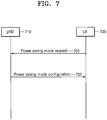
- FIG. 7 illustrates how to reduce power consumption of a terminal in a wireless communication system, according to an embodiment of the disclosure.
- FIG. 7 illustrates an operation procedure between a base station (gNB) 710 and a user equipment (UE) 720 based on power saving mode operations of the UE.
- gNB base station
- UE user equipment
- the UE 720 may transmit a message requesting a power saving mode (in the disclosure, it is called a power saving mode request (PSR)) to the gNB 710.
- PSR power saving mode request
- the UE 720 may notify the gNB 710 of the PSR message through higher layer signaling (e.g., medium access control (MAC) control element (CE) or remote radio control (RRC) signaling) or L1 signaling (e.g., a PUCCH, a PUSCH, or a physical layer channel on which a PSR may be transmitted).
- higher layer signaling e.g., medium access control (MAC) control element (CE) or remote radio control (RRC) signaling
- L1 signaling e.g., a PUCCH, a PUSCH, or a physical layer channel on which a PSR may be transmitted.
- the gNB 710 may transmit configuration information or an indicator related to the power saving mode to the UE 720.
- the configuration information relating to the power saving mode may be notified to the UE 720 from the gNB 710 through higher layer signaling (e.g., MAC CE or RRC signaling), and the indicator related to the power saving mode may be notified to the UE 720 from the gNB 710 through L1 signaling (e.g., DCI).
- higher layer signaling e.g., MAC CE or RRC signaling
- L1 signaling e.g., DCI
- the PSR message may include one or more of the following pieces of information.
- the UE may transmit the PSR message to the gNB by using a PUCCH.
- the gNB may pre-configure a PUCCH resource on which to transmit the PSR message to the UE.
- the UE may transmit the PSR message on the PUCCH resource configured for the PSR message.
- the PSR message may be multiplexed with a PUCCH on which other UCI (e.g., a scheduling request (SR), HARQ-ACK, channel quality information (CQI), etc.) is transmitted and then transmitted.
- UCI e.g., a scheduling request (SR), HARQ-ACK, channel quality information (CQI), etc.
- the UE may transmit the PSR message to the gNB by using a PUSCH.
- a resource region in the PUSCH on which the PSR message is transmitted may be predefined or determined by a length of the other UCI message (e.g., SR, HARQ-ACK, CQI, etc.).
- the UE may transmit the PSR message to the gNB by using a physical layer channel dedicated to the PSR message (referred to as a PSRCH).
- the gNB may notify the UE of configuration information for the PSRCH through higher layer signaling, e.g., RRC signaling.
- the configuration information for the PSRCH may include one or more of the following pieces of information.
- the UE may transmit the PSR message to the gNB by higher layer signaling, e.g., MAC CE or RRC signaling.
- higher layer signaling e.g., MAC CE or RRC signaling.
- the gNB may configure all or part of the following contents for the UE through higher layer signaling (e.g., MAC CE or RRC signaling).
- higher layer signaling e.g., MAC CE or RRC signaling.
- the gNB may further configure a bandwidth part having narrow bandwidth (e.g., bandwidth equal to or less than X1 RBs) for the UE.
- the UE is configured to operate in a very narrow bandwidth part having X1 or less bandwidth, thereby significantly reducing power consumed at a radio frequency (RF) stage of the UE.
- the value X1 may be predefined.
- the value X1 may correspond to a size equal to an initial bandwidth part or the value X1 may be reported by the UE to the gNB in a UE capability.
- the value X1 may be notified by the UE to the gNB by higher layer signaling, e.g., in an MAC CE or RRC message.
- the value X1 may be notified by the UE to the gNB through L1 signaling, e.g., a PUCCH, a PUSCH, or a physical layer channel on which a PSR may be transmitted.
- the gNB may configure a configuration value of a monitoring periodicity to be a value equal to or greater than X2 among search space related configuration information (Table 8) for the PDCCH for the UE.
- search space related configuration information Table 8
- the value X2 may be predefined.
- the value X2 may be reported by the UE to the gNB in a UE capability.
- the value X2 may be notified by the UE to the gNB by higher layer signaling, e.g., in an MAC CE or RRC message.
- the value X2 may be notified by the UE to the gNB through L1 signaling, e.g., a PUCCH, a PUSCH, or a physical layer channel on which a PSR may be transmitted.
- the gNB may configure a value of the number of PDCCH candidates so that a total sum of the number of PDCCH candidates to be monitored for overall slots to have a value equal to or less than X3 among the search space related configuration information (Table 8) for the PDCCH for the UE.
- X3 may be predefined. Or the value X3 may be reported by the UE to the gNB in a capability.
- the subcarrier spacing may be defined to be 15 ⁇ 2 ⁇ kHz.
- the gNB may always configure the UE to perform transmission or reception only with X4 or less layers (or equally configure the UE to use always X4 or less DMRS ports) in transmitting or receiving a data channel, i.e., a PDSCH or a PUSCH.
- a data channel i.e., a PDSCH or a PUSCH.
- the UE may only assume a small number of layers for data transmission or reception, the UE may keep the number of active antennas small, thereby significantly reducing power consumption from this.
- the value X4 may be predefined (e.g., X4 may correspond to 1 or 2). Or the value X4 may be reported by the UE to the gNB in a UE capability.
- the value X4 may be notified by the UE to the gNB by higher layer signaling, e.g., in an MAC CE or RRC message. Or the value X4 may be notified by the UE to the gNB through L1 signaling, e.g., a PUCCH, a PUSCH, or a physical layer channel on which a PSR may be transmitted.
- L1 signaling e.g., a PUCCH, a PUSCH, or a physical layer channel on which a PSR may be transmitted.
- the gNB may indicate all or part of the following contents to the UE through L1 signaling (e.g., DCI).
- the gNB may indicate a change in bandwidth part to a bandwidth part corresponding to narrow bandwidth in DCI to the UE. For example, when a bandwidth part #1 corresponding to 100 MHz and a bandwidth part #2 corresponding to 10 MHz are configured for the UE and a currently active bandwidth part corresponds to the bandwidth part #1, the BS may transmit DCI indicating a change to the bandwidth part #2 to the UE.
- the UE may operate in a bandwidth part corresponding to narrow bandwidth and thus, significantly reduce power consumption at an RF stage of the UE.
- the gNB may schedule a data channel, a PDSCH or a PUSCH always with Y1 or less layers.
- the UE that has transmitted the PSR may expect that the data channel is scheduled with Y1 or less layers.
- the UE may activate a fewer number of antennas to be operated, thereby reducing power consumption.
- the value Y1 may be predefined (e.g., Y1 may correspond to 1 or 2). Or the value Y1 may be reported by the UE to the gNB in a UE capability.
- the value Y1 may be notified by the UE to the gNB by higher layer signaling, e.g., in an MAC CE or RRC message. Or the value Y1 may be notified by the UE to the gNB through L1 signaling, e.g., a PUCCH, a PUSCH, or a physical layer channel on which a PSR may be transmitted.
- L1 signaling e.g., a PUCCH, a PUSCH, or a physical layer channel on which a PSR may be transmitted.
- the UE that has transmitted the PSR message and operated in the power saving mode may release the power saving mode through additional signaling.
- the UE may transmit a message corresponding to power saving mode release (referred to as a power saving mode release request (PSR2)) to the gNB.
- PSR2 power saving mode release request
- the UE may notify the PSR2 message to the gNB through higher layer signaling (e.g., MAC CE or RRC signaling) or L1 signaling (e.g., a PUCCH, a PUSCH, or a physical layer channel on which a PSR may be transmitted or a physical layer channel on the PSR2 may be transmitted).
- higher layer signaling e.g., MAC CE or RRC signaling
- L1 signaling e.g., a PUCCH, a PUSCH, or a physical layer channel on which a PSR may be transmitted or a physical layer channel on the PSR2 may be transmitted.
- the gNB having received the power saving mode release request message, i.e., the PSR2 message, from the UE does not need to necessarily notify configuration information or an indicator related to the power saving mode defined for the UE, and may freely operate parameters related to data transmission or reception.
- FIG. 8 is a flowchart illustrating an operation method, performed by a terminal, for reducing power consumption of the terminal in a wireless communication system, according to an embodiment.
- a terminal transmits a power saving mode request (PSR) message requesting a power saving mode to a base station.
- the terminal may need to operate in the power saving mode for various reasons. For example, the terminal may request the power saving mode from the base station for such reasons as having little battery left, having requirement for reducing power consumption as much as possible at a user's request, etc.
- the terminal may transmit the PSR message to the base station according to a preset reference or an input from the user.
- the terminal receives configuration information or indicator information relating to the power saving mode from the base station.
- the terminal may operate in the power saving mode by operating to reflect the configuration information or the indicator information.
- the configuration information or the indicator information relating to the power saving mode may include configuration information or indicator information based on information included in the PSR message in operation 810.
- FIG. 9 is a flowchart illustrating an operation method, performed by a base station, for reducing power consumption of a terminal in a wireless communication system, according to an embodiment.
- a base station receives a PSR message requesting the power saving mode from a terminal.
- the PSR message may include various information according to settings of the terminal.
- the base station transmits configuration information or indicator information relating to the power saving mode to the terminal in response to the PSR message.
- the configuration information or the indicator information may be transmitted to the terminal.
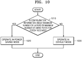
- FIG. 10 is a flowchart illustrating a method of reducing power consumption of a terminal in a wireless communication system, according to another embodiment.
- the terminal In a 5G or NR system, it is recommended for the terminal to operate 4 receive antenna ports as default. When the terminal operates at least 4 receive antenna ports, an amount of power consumption of the terminal may significantly increase. In the disclosure, a method by which power consumption of the terminal may be reduced by allowing the terminal to operate with less than 4 antenna ports according to a configuration of the base station in a situation where the terminal operates with at least 4 receive antenna ports is described.
- the base station may configure the maximum number X of layers for a PDSCH for the terminal.
- X may have a value of 1 or 2.
- the base station may always schedule and transmit only a PDSCH corresponding to X or less layers, and notify the terminal of the corresponding scheduling information in DCI.
- the terminal may not expect transmission of the PDSCH with X or more layers. Accordingly, the terminal may operate as many antenna ports as it may receive X layers.
- the base station may configure the maximum number Y of DMRS ports for a PDSCH for the terminal.
- Y may have a value of 1 or 2.
- the base station may always use DMRSs corresponding to X or less DMRS ports for transmission, and notify the terminal of the corresponding DMRS information in DCI.
- the terminal may not expect transmission of the PDSCH with Y or more DMRS ports. Accordingly, the terminal may operate as many antenna ports as it may operate Y DMRS ports.
- the terminal may determine whether the terminal has received configuration information about the maximum number of layers or maximum number of DMRS ports for the PDSCH from the base station, in operation 1010.
- the terminal may proceed to operation 1020 to operate in the power saving mode.
- the power saving mode may correspond to an operation to activate antennas as little as possible, which are required to support e.g., the maximum number of layers or DMRS ports configured from the base station.
- the terminal may proceed to operation 1030 to operate in a default mode.
- the default mode may correspond to an operation to activate antennas required to support e.g., the number of layers or DMRS ports corresponding to a UE capability.
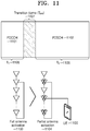
- FIG. 11 illustrates how to reduce power consumption of a terminal in a wireless communication system, according to another embodiment.
- the terminal In a 5G or NR system, it is recommended for the terminal to operate 4 receive antenna ports as default. When the terminal operates with at least 4 receive antenna ports, an amount of power consumption of the terminal may significantly increase as physical antennas corresponding to the corresponding antenna ports need to be all activated.
- a method by which a terminal partially activates and operates antenna ports or physical antennas corresponding to the antenna ports to receive a PDSCH based on scheduling information for the PDSCH indicated in DCI is described.
- a terminal (UE) 1100 may activate (1103) all of the antennas (or equally, physical antennas for reception through at least 4 receive antenna ports) for reception for a period of time T1 (1105) to receive and monitor a PDCCH 1101.
- the UE 1100 may receive DCI including scheduling information for a PDSCH 1102 from the PDCCH 1101.
- the UE 1100 may receive the PDSCH 1102 by only activating some of antennas (or equally, physical antennas for reception with less than 4 antenna ports) for a period of time T2 (1106) to receive and decode the PDSCH.
- the transition time 1107 required to deactivate some of the entire antennas and activate only the other antennas may be a transition time 1107 required to deactivate some of the entire antennas and activate only the other antennas.
- the transition time 1107 required to change the extent of antenna activation is defined as T gap .
- the UE 1100 may have a power saving effect from the antenna deactivation by activating some of antennas (1104) while receiving the PDSCH 1102.
- FIG. 12 is a flowchart illustrating a method of reducing power consumption of a terminal in a wireless communication system, according to another embodiment.
- a terminal may activate all of the antennas (or equally, physical antennas for reception with at least 4 receive antenna ports) to monitor a PDCCH, in operation 1210. Subsequently, the terminal may obtain scheduling DCI for a PDSCH, in operation 1220. In an embodiment, the terminal may receive configuration information about the number of layers or DMRS ports for the PDSCH. For example, the terminal may obtain the following pieces of information as some of the scheduling information for the PDSCH from the DCI. [Table 15] resource allocation information on time axis - 1, 2, 3, or 4 bits (index of slot in which PDSCH is scheduled, starting symbol position, symbol length, PDSCH mapping type, etc.) - antenna port information - 4. 5 or 6 bits (number of DMRS CDM groups, DMRS port number, the number of symbols of front-load DMRS, etc.)
- the terminal may determine whether the number of layers or DMRS ports obtained from antenna port information for the PDSCH is less than X, in operation 1230.
- X may correspond to a threshold value predefined for determination to activate some of antennas, e.g., X may be 3 or 4.
- the terminal may proceed to operation 1240 to determine whether a time gap between a starting time of the PDSCH obtained from resource allocation information on the time axis for the PDSCH and a time at which a PDCCH is received is greater than T gap .
- the terminal may proceed to operation 1260 to receive the scheduled PDSCH by activating only some of antennas after the time T gap .
- the terminal may proceed to operation 1250 to receive the scheduled PDSCH by activating all of the antennas.
- the terminal may proceed to operation 1250 to activate all of the antennas and receive the scheduled PDSCH.
- FIG. 13 is a block diagram of an internal structure of a terminal, according to an embodiment.
- a terminal 1300 may include a transceiver 1310, a memory 1320, and a processor 1330.
- the transceiver 1310, the memory 1320, and the processor 1330 of the terminal 1300 may operate according to the aforementioned communication method of the terminal 1300. Elements of the terminal 1300 are not, however, limited thereto. For example, the terminal 1300 may include more or fewer elements than described above.
- the transceiver 1310, the memory 1320, and the processor 1330 may be implemented in a single chip.
- the transceiver 1310 may transmit or receive signals to or from a base station.
- the signals may include control information and data.
- the transceiver 1310 may include an RF transmitter for up-converting the frequency of a signal to be transmitted and amplifying the signal and an RF receiver for low-noise amplifying a received signal and down-converting the frequency of the received signal. It is merely an example of the transceiver 1310, and the elements of the transceiver 1310 are not limited to the RF transmitter and RF receiver.
- the transceiver 1310 may receive a signal on a wireless channel and output the signal to the processor 1330, or transmit a signal output from the processor 1330 on a wireless channel.
- the memory 1320 may store a program and data required for operation of the terminal 1300. Furthermore, the memory 1320 may store control information or data included in a signal obtained by the terminal 1300.
- the memory 1320 may include a storage medium such as a ROM, a RAM, a hard disk, a CD-ROM, and a DVD, or a combination of storage mediums. Moreover, the memory 1320 may be in the plural. In an embodiment, the memory 1320 may store a program to support beam based cooperative communication.
- the processor 1330 may control a series of processes for the terminal 1300 to be operated according to the aforementioned embodiments. For example, it may control operations to transmit or receive an up/downlink control channel and a data channel in consideration of a PSR message transmission method, a power saving mode operation method, some of antenna activation method, etc., in accordance with embodiments.
- the processor 1330 may be in the plural.
- the processor 1330 may execute the program stored in the memory 1320 to control a PSR message requesting the power saving mode to be transmitted to the base station and configuration information or indicator information relating to the power saving mode to be received from the base station.
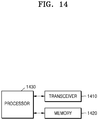
- FIG. 14 is a block diagram of an internal structure of a base station, according to an embodiment.
- a base station 1400 may include a transceiver 1410, a memory 1420, and a processor 1430.
- the transceiver 1410, the memory 1420, and the processor 1430 of the base station 1400 may operate according to the aforementioned communication method of the base station 1400. Elements of the base station1400 are not, however, limited thereto.
- the base station 1400 may include more or fewer elements than described above.
- the transceiver 1410, the memory 1420, and the processor 1430 may be implemented in a single chip.
- the transceiver 1410 may transmit or receive signals to or from a terminal.
- the signals may include control information and data.
- the transceiver 1410 may include an RF transmitter for up-converting the frequency of a signal to be transmitted and amplifying the signal and an RF receiver for low-noise amplifying a received signal and down-converting the frequency of the received signal. It is merely an example of the transceiver 1410, and the elements of the transceiver 1410 are not limited to the RF transmitter and RF receiver.
- the transceiver 1410 may receive a signal on a wireless channel and output the signal to the processor 1430, or transmit a signal output from the processor 1430 on a wireless channel.
- the memory 1420 may store a program and data required for operation of the base station 1400. Furthermore, the memory 1420 may store control information or data included in a signal obtained by the base station 1400.
- the memory 1420 may include a storage medium such as a ROM, a RAM, a hard disk, a CD-ROM, and a DVD, or a combination of storage mediums. Moreover, the memory 1420 may be in the plural. In an embodiment, the memory 1420 may store a program to support beam based cooperative communication.
- the processor 1430 may control a series of processes for the base station 1400 to operate in accordance with the embodiments of the present disclosure. For example, it may control operations to transmit or receive an up/downlink control channel and a data channel in consideration of a PSR message transmission resource configuration method, a power saving mode configuration method, a DMRS port number configuration method, etc., in accordance with embodiments of the disclosure.
- the processor 1330 may be in the plural.
- the processor 1430 may execute the program stored in the memory 1420 to control a PSR message requesting the power saving mode to be received from the terminal and configuration information or indicator information relating to the power saving mode to be transmitted to the terminal in response to the PSR message.
- a computer-readable storage medium storing one or more programs (software modules) may be provided.
- the one or more programs stored in the computer-readable storage medium are configured for execution by one or more processors in an electronic device.
- the one or more programs may include instructions that cause the electronic device to perform the methods in accordance with the claims of the disclosure or the embodiments described in the specification.
- the programs may be stored in a random access memory (RAM), a non-volatile memory including a flash memory, a read only memory (ROM), an electrically erasable programmable ROM (EEPROM), a magnetic disc storage device, a compact disc-ROM (CD-ROM), a digital versatile disc (DVD) or other types of optical storage device, and/or a magnetic cassette.
- RAM random access memory
- ROM read only memory
- EEPROM electrically erasable programmable ROM
- magnetic disc storage device a compact disc-ROM (CD-ROM), a digital versatile disc (DVD) or other types of optical storage device, and/or a magnetic cassette.
- CD-ROM compact disc-ROM
- DVD digital versatile disc
- the programs may be stored in a memory including a combination of some or all of them. There may be a plurality of memories.
- the program may also be stored in an attachable storage device that may be accessed over a communication network including the Internet, an intranet, a LAN, a wide LAN (WLAN), or a storage area network (SAN), or a combination thereof.
- the storage device may be connected to an apparatus performing the embodiments of the disclosure through an external port.
- an extra storage device in the communication network may access a device that performs the embodiments of the disclosure.
- a component is represented in a singular or plural form. It should be understood, however, that the singular or plural representations are selected appropriately according to the situations presented for convenience of explanation, and the disclosure is not limited to the singular or plural form of the component. Further, the component expressed in the plural form may also imply the singular form, and vice versa.
Landscapes
- Engineering & Computer Science (AREA)
- Computer Networks & Wireless Communication (AREA)
- Signal Processing (AREA)
- Databases & Information Systems (AREA)
- Mobile Radio Communication Systems (AREA)
Applications Claiming Priority (2)
| Application Number | Priority Date | Filing Date | Title |
|---|---|---|---|
| KR1020180044119A KR102464908B1 (ko) | 2018-04-16 | 2018-04-16 | 무선 통신 시스템에서 단말의 전력 소모 감소를 위한 방법 및 장치 |
| PCT/KR2019/004567 WO2019203530A1 (fr) | 2018-04-16 | 2019-04-16 | Procédé et appareil de réduction de la consommation d'énergie d'un terminal dans un système de communication sans fil |
Publications (2)
| Publication Number | Publication Date |
|---|---|
| EP3780767A1 true EP3780767A1 (fr) | 2021-02-17 |
| EP3780767A4 EP3780767A4 (fr) | 2021-05-26 |
Family
ID=68239184
Family Applications (1)
| Application Number | Title | Priority Date | Filing Date |
|---|---|---|---|
| EP19788011.5A Pending EP3780767A4 (fr) | 2018-04-16 | 2019-04-16 | Procédé et appareil de réduction de la consommation d'énergie d'un terminal dans un système de communication sans fil |
Country Status (4)
| Country | Link |
|---|---|
| US (1) | US11765660B2 (fr) |
| EP (1) | EP3780767A4 (fr) |
| KR (1) | KR102464908B1 (fr) |
| WO (1) | WO2019203530A1 (fr) |
Cited By (2)
| Publication number | Priority date | Publication date | Assignee | Title |
|---|---|---|---|---|
| EP3826370A4 (fr) * | 2018-08-10 | 2021-09-22 | Huawei Technologies Co., Ltd. | Procédé et appareil de transmission de données |
| US20220159568A1 (en) * | 2019-01-11 | 2022-05-19 | Samsung Electronics Co., Ltd. | Method and apparatus for transmitting and receiving terminal support information in wireless communication system |
Families Citing this family (22)
| Publication number | Priority date | Publication date | Assignee | Title |
|---|---|---|---|---|
| WO2019215872A1 (fr) * | 2018-05-10 | 2019-11-14 | 株式会社Nttドコモ | Terminal utilisateur et station de base sans fil |
| ES2960740T3 (es) * | 2018-05-18 | 2024-03-06 | Ntt Docomo Inc | Terminal, método y sistema correspondientes |
| KR102664932B1 (ko) | 2018-09-03 | 2024-05-10 | 삼성전자주식회사 | 무선통신 시스템에서 단말 안테나 설정 방법 및 장치 |
| CN113727421B (zh) * | 2018-10-19 | 2023-10-17 | 北京小米移动软件有限公司 | 省电信号监听方法及装置 |
| KR102890810B1 (ko) | 2019-02-14 | 2025-11-26 | 삼성전자주식회사 | 무선 통신 시스템에서 단말의 전력 소모 감소 방법 및 장치 |
| US11438775B2 (en) * | 2019-05-02 | 2022-09-06 | Ofinno, Llc | Radio link monitoring in new radio |
| CN112312547B (zh) * | 2019-07-26 | 2024-09-13 | 大唐移动通信设备有限公司 | 资源分配、确定方法及装置 |
| KR102613219B1 (ko) | 2019-08-07 | 2023-12-13 | 삼성전자 주식회사 | 무선 통신 시스템에서 안테나 적응 방법 및 장치 |
| US11871215B2 (en) * | 2019-09-18 | 2024-01-09 | Qualcomm Incorporated | Uplink-centric handover in a wireless multi-hop network |
| US11729718B2 (en) * | 2019-09-30 | 2023-08-15 | Qualcomm Incorporated | Triggering power saving modes with scheduling downlink control information |
| CN120711530A (zh) * | 2020-08-14 | 2025-09-26 | 中兴通讯股份有限公司 | 用于放宽的ue处理时间的方法 |
| WO2022087056A1 (fr) * | 2020-10-20 | 2022-04-28 | Ofinno, Llc | Gestion de ressources associée à des services de multidiffusion et de diffusion |
| US11997034B2 (en) * | 2021-05-13 | 2024-05-28 | Qualcomm Incorporated | Control of scrambling sequence per symbol for digital post distortion |
| US11438122B2 (en) * | 2021-06-14 | 2022-09-06 | Ultralogic 6G, Llc | Custom downlink search-spaces for low-complexity 5G/6G messaging |
| US11611459B1 (en) * | 2021-08-25 | 2023-03-21 | Qualcomm Incorporated | Symbol configuration for single-carrier for frequency domain equalization waveform |
| JP7534276B2 (ja) * | 2021-09-30 | 2024-08-14 | トヨタ自動車株式会社 | 送信制御方法、及び情報処理装置 |
| US12464455B2 (en) * | 2021-12-14 | 2025-11-04 | Qualcomm Incorporated | Communications in power saving mode |
| CN118075846A (zh) * | 2022-11-23 | 2024-05-24 | 华为技术有限公司 | 通信方法和通信装置 |
| US20240276380A1 (en) * | 2023-02-15 | 2024-08-15 | Samsung Electronics Co., Ltd. | Ue mode switching for power saving in wireless communication |
| US20250048260A1 (en) * | 2023-07-31 | 2025-02-06 | Qualcomm Incorporated | User equipment request for operation state |
| KR20250069325A (ko) * | 2023-11-10 | 2025-05-19 | 삼성전자주식회사 | 무선 통신 시스템에서 단말의 전력 상태를 고려한 통신 제어 방법 및 장치 |
| US20250310890A1 (en) * | 2024-03-26 | 2025-10-02 | Dish Wireless L.L.C. | System and method for improving battery life of a user equipment (ue) in a 5g network |
Family Cites Families (12)
| Publication number | Priority date | Publication date | Assignee | Title |
|---|---|---|---|---|
| KR100411902B1 (ko) * | 2001-08-11 | 2003-12-24 | 주식회사 케이티프리텔 | 이동통신 시스템에서의 비상호 처리를 위한 전력 관리방법 |
| US7583984B2 (en) | 2005-08-12 | 2009-09-01 | Lg Electronics Inc. | Method of providing notification for battery power conservation in a wireless system |
| KR101544150B1 (ko) * | 2009-03-26 | 2015-08-12 | 삼성전자주식회사 | 무선통신시스템에서 서비스 품질을 향상시키기 위한 장치 및 방법 |
| KR101669969B1 (ko) * | 2009-12-09 | 2016-11-09 | 엘지전자 주식회사 | 무선 통신 시스템에서 파워 세이빙 방법 |
| US20130265922A1 (en) | 2012-04-09 | 2013-10-10 | Qualcomm Incorporated | Apparatus and method of managing a power saving request |
| CN103686952B (zh) * | 2012-09-17 | 2019-03-12 | 中兴通讯股份有限公司 | 一种节能方法、用户设备和网络侧网元 |
| US9420511B2 (en) * | 2012-11-01 | 2016-08-16 | Intel Corporation | Signaling QoS requirements and UE power preference in LTE-A networks |
| SG11201710733WA (en) * | 2015-07-03 | 2018-01-30 | Sharp Kk | Terminal device, base station device, communication method and integrated circuit |
| US11044709B2 (en) | 2016-03-11 | 2021-06-22 | Qualcomm Incorporated | Power savings for downlink channel monitoring in narrowband systems |
| US10757601B2 (en) * | 2017-12-13 | 2020-08-25 | At&T Intellectual Property I, L.P. | Physical layer procedures for user equipment in power saving mode |
| US10973008B2 (en) * | 2018-03-12 | 2021-04-06 | Apple Inc. | Wireless device preferred bandwidth part configuration and duty cycle indication |
| US11589305B2 (en) * | 2018-03-12 | 2023-02-21 | Apple Inc. | Scheduling profile for UE power savings |
-
2018
- 2018-04-16 KR KR1020180044119A patent/KR102464908B1/ko active Active
-
2019
- 2019-04-16 WO PCT/KR2019/004567 patent/WO2019203530A1/fr not_active Ceased
- 2019-04-16 EP EP19788011.5A patent/EP3780767A4/fr active Pending
- 2019-04-16 US US17/048,560 patent/US11765660B2/en active Active
Cited By (4)
| Publication number | Priority date | Publication date | Assignee | Title |
|---|---|---|---|---|
| EP3826370A4 (fr) * | 2018-08-10 | 2021-09-22 | Huawei Technologies Co., Ltd. | Procédé et appareil de transmission de données |
| US12016043B2 (en) | 2018-08-10 | 2024-06-18 | Huawei Technologies Co., Ltd. | Data transmission method and apparatus |
| US20220159568A1 (en) * | 2019-01-11 | 2022-05-19 | Samsung Electronics Co., Ltd. | Method and apparatus for transmitting and receiving terminal support information in wireless communication system |
| US12022387B2 (en) | 2019-01-11 | 2024-06-25 | Samsung Electronics Co., Ltd | Method and apparatus for transmitting and receiving terminal support information in wireless communication system |
Also Published As
| Publication number | Publication date |
|---|---|
| KR102464908B1 (ko) | 2022-11-08 |
| WO2019203530A1 (fr) | 2019-10-24 |
| EP3780767A4 (fr) | 2021-05-26 |
| US11765660B2 (en) | 2023-09-19 |
| US20210329556A1 (en) | 2021-10-21 |
| KR20190120665A (ko) | 2019-10-24 |
Similar Documents
| Publication | Publication Date | Title |
|---|---|---|
| US11765660B2 (en) | Method and apparatus for reducing power consumption of terminal in wireless communication system | |
| EP3977663B1 (fr) | Procédé et appareil pour améliorer la couverture pour pdcch dans un système de communication sans fil | |
| US11595181B2 (en) | Method and apparatus for transmitting different uplink control information in wireless communication system | |
| EP3837800B1 (fr) | Procédé et appareil pour la transmission et la réception d'un canal de couche physique en fonction d'une priorité dans un système de communication sans fil | |
| US12022387B2 (en) | Method and apparatus for transmitting and receiving terminal support information in wireless communication system | |
| US11166285B2 (en) | Downlink control channel configuration method and apparatus in wireless communication system for reducing power consumption of terminal | |
| EP3681090B1 (fr) | Procédé et appareil de transmission d'informations de commande de liaison descendante dans un système de communication sans fil | |
| US20230217458A1 (en) | Method and apparatus for performing communication in wireless communication system | |
| EP3910860A1 (fr) | Procédé et appareil permettant de transmettre et de recevoir des informations de commande de liaison descendante dans un système de communication sans fil | |
| US12464601B2 (en) | Method and apparatus for monitoring control information in wireless communication system | |
| EP4022831B1 (fr) | Procédé et appareil de transmission de canal physique de commande de liaison descendante en système de communication sans fil | |
| EP3855663B1 (fr) | Procédé et dispositif de transmission et de réception de signaux dans un système de communication sans fil | |
| EP3881612B1 (fr) | Procédé et appareil de réduction de la consommation d'énergie d'un terminal dans un système de communication sans fil | |
| KR20200036655A (ko) | 무선 통신 시스템에서 pdcch 모니터링 방법 및 장치 | |
| US20200267652A1 (en) | Uplink control channel transmitting method and apparatus for reducing power consumption of user equipment in wireless communication system | |
| EP3958637A1 (fr) | Procédé et dispositif de transmission d'informations de commande dans un système de communication sans fil | |
| US12143935B2 (en) | Method and apparatus for transmitting and receiving power saving signal in wireless communication system | |
| KR20190072380A (ko) | 무선 통신 시스템에서 하향링크 제어정보 설정 방법 및 장치 | |
| KR20220115008A (ko) | 무선 통신 시스템에서 셀 간 간섭 제어를 위한 방법 및 장치 | |
| RU2774980C2 (ru) | Способ и оборудование для передачи различной управляющей информации восходящей линии связи в системе беспроводной связи |
Legal Events
| Date | Code | Title | Description |
|---|---|---|---|
| STAA | Information on the status of an ep patent application or granted ep patent |
Free format text: STATUS: THE INTERNATIONAL PUBLICATION HAS BEEN MADE |
|
| PUAI | Public reference made under article 153(3) epc to a published international application that has entered the european phase |
Free format text: ORIGINAL CODE: 0009012 |
|
| STAA | Information on the status of an ep patent application or granted ep patent |
Free format text: STATUS: REQUEST FOR EXAMINATION WAS MADE |
|
| 17P | Request for examination filed |
Effective date: 20201027 |
|
| AK | Designated contracting states |
Kind code of ref document: A1 Designated state(s): AL AT BE BG CH CY CZ DE DK EE ES FI FR GB GR HR HU IE IS IT LI LT LU LV MC MK MT NL NO PL PT RO RS SE SI SK SM TR |
|
| AX | Request for extension of the european patent |
Extension state: BA ME |
|
| A4 | Supplementary search report drawn up and despatched |
Effective date: 20210423 |
|
| RIC1 | Information provided on ipc code assigned before grant |
Ipc: H04W 52/02 20090101AFI20210419BHEP Ipc: H04W 72/04 20090101ALI20210419BHEP |
|
| DAV | Request for validation of the european patent (deleted) | ||
| DAX | Request for extension of the european patent (deleted) | ||
| STAA | Information on the status of an ep patent application or granted ep patent |
Free format text: STATUS: EXAMINATION IS IN PROGRESS |
|
| 17Q | First examination report despatched |
Effective date: 20230201 |