EP3780773A1 - Leistungsregelungsverfahren für sidelink und endgerät - Google Patents
Leistungsregelungsverfahren für sidelink und endgerät Download PDFInfo
- Publication number
- EP3780773A1 EP3780773A1 EP19786105.7A EP19786105A EP3780773A1 EP 3780773 A1 EP3780773 A1 EP 3780773A1 EP 19786105 A EP19786105 A EP 19786105A EP 3780773 A1 EP3780773 A1 EP 3780773A1
- Authority
- EP
- European Patent Office
- Prior art keywords
- terminal device
- information
- power control
- power
- indication information
- Prior art date
- Legal status (The legal status is an assumption and is not a legal conclusion. Google has not performed a legal analysis and makes no representation as to the accuracy of the status listed.)
- Granted
Links
Images


Classifications
-
- H—ELECTRICITY
- H04—ELECTRIC COMMUNICATION TECHNIQUE
- H04W—WIRELESS COMMUNICATION NETWORKS
- H04W52/00—Power management, e.g. Transmission Power Control [TPC] or power classes
- H04W52/04—Transmission power control [TPC]
- H04W52/38—TPC being performed in particular situations
- H04W52/383—TPC being performed in particular situations power control in peer-to-peer links
-
- H—ELECTRICITY
- H04—ELECTRIC COMMUNICATION TECHNIQUE
- H04W—WIRELESS COMMUNICATION NETWORKS
- H04W52/00—Power management, e.g. Transmission Power Control [TPC] or power classes
- H04W52/04—Transmission power control [TPC]
- H04W52/06—TPC algorithms
- H04W52/14—Separate analysis of uplink or downlink
- H04W52/146—Uplink power control
-
- H—ELECTRICITY
- H04—ELECTRIC COMMUNICATION TECHNIQUE
- H04W—WIRELESS COMMUNICATION NETWORKS
- H04W52/00—Power management, e.g. Transmission Power Control [TPC] or power classes
- H04W52/04—Transmission power control [TPC]
- H04W52/06—TPC algorithms
- H04W52/08—Closed loop power control
-
- H—ELECTRICITY
- H04—ELECTRIC COMMUNICATION TECHNIQUE
- H04L—TRANSMISSION OF DIGITAL INFORMATION, e.g. TELEGRAPHIC COMMUNICATION
- H04L1/00—Arrangements for detecting or preventing errors in the information received
- H04L1/0001—Systems modifying transmission characteristics according to link quality, e.g. power backoff
- H04L1/0023—Systems modifying transmission characteristics according to link quality, e.g. power backoff characterised by the signalling
- H04L1/0026—Transmission of channel quality indication
-
- H—ELECTRICITY
- H04—ELECTRIC COMMUNICATION TECHNIQUE
- H04L—TRANSMISSION OF DIGITAL INFORMATION, e.g. TELEGRAPHIC COMMUNICATION
- H04L1/00—Arrangements for detecting or preventing errors in the information received
- H04L1/12—Arrangements for detecting or preventing errors in the information received by using return channel
- H04L1/16—Arrangements for detecting or preventing errors in the information received by using return channel in which the return channel carries supervisory signals, e.g. repetition request signals
- H04L1/18—Automatic repetition systems, e.g. Van Duuren systems
- H04L1/1812—Hybrid protocols; Hybrid automatic repeat request [HARQ]
- H04L1/1819—Hybrid protocols; Hybrid automatic repeat request [HARQ] with retransmission of additional or different redundancy
-
- H—ELECTRICITY
- H04—ELECTRIC COMMUNICATION TECHNIQUE
- H04L—TRANSMISSION OF DIGITAL INFORMATION, e.g. TELEGRAPHIC COMMUNICATION
- H04L1/00—Arrangements for detecting or preventing errors in the information received
- H04L1/20—Arrangements for detecting or preventing errors in the information received using signal quality detector
- H04L1/203—Details of error rate determination, e.g. BER, FER or WER
-
- H—ELECTRICITY
- H04—ELECTRIC COMMUNICATION TECHNIQUE
- H04L—TRANSMISSION OF DIGITAL INFORMATION, e.g. TELEGRAPHIC COMMUNICATION
- H04L5/00—Arrangements affording multiple use of the transmission path
- H04L5/003—Arrangements for allocating sub-channels of the transmission path
- H04L5/0053—Allocation of signalling, i.e. of overhead other than pilot signals
- H04L5/0055—Physical resource allocation for ACK/NACK
-
- H—ELECTRICITY
- H04—ELECTRIC COMMUNICATION TECHNIQUE
- H04W—WIRELESS COMMUNICATION NETWORKS
- H04W52/00—Power management, e.g. Transmission Power Control [TPC] or power classes
- H04W52/04—Transmission power control [TPC]
- H04W52/06—TPC algorithms
- H04W52/16—Deriving transmission power values from another channel
-
- H—ELECTRICITY
- H04—ELECTRIC COMMUNICATION TECHNIQUE
- H04W—WIRELESS COMMUNICATION NETWORKS
- H04W52/00—Power management, e.g. Transmission Power Control [TPC] or power classes
- H04W52/04—Transmission power control [TPC]
- H04W52/54—Signalisation aspects of the TPC commands, e.g. frame structure
-
- H—ELECTRICITY
- H04—ELECTRIC COMMUNICATION TECHNIQUE
- H04W—WIRELESS COMMUNICATION NETWORKS
- H04W52/00—Power management, e.g. Transmission Power Control [TPC] or power classes
- H04W52/04—Transmission power control [TPC]
- H04W52/18—TPC being performed according to specific parameters
- H04W52/22—TPC being performed according to specific parameters taking into account previous information or commands
-
- H—ELECTRICITY
- H04—ELECTRIC COMMUNICATION TECHNIQUE
- H04W—WIRELESS COMMUNICATION NETWORKS
- H04W52/00—Power management, e.g. Transmission Power Control [TPC] or power classes
- H04W52/04—Transmission power control [TPC]
- H04W52/18—TPC being performed according to specific parameters
- H04W52/22—TPC being performed according to specific parameters taking into account previous information or commands
- H04W52/225—Calculation of statistics, e.g. average or variance
-
- H—ELECTRICITY
- H04—ELECTRIC COMMUNICATION TECHNIQUE
- H04W—WIRELESS COMMUNICATION NETWORKS
- H04W52/00—Power management, e.g. Transmission Power Control [TPC] or power classes
- H04W52/04—Transmission power control [TPC]
- H04W52/18—TPC being performed according to specific parameters
- H04W52/24—TPC being performed according to specific parameters using SIR [Signal to Interference Ratio] or other wireless path parameters
- H04W52/241—TPC being performed according to specific parameters using SIR [Signal to Interference Ratio] or other wireless path parameters taking into account channel quality metrics, e.g. SIR, SNR, CIR or Eb/lo
-
- H—ELECTRICITY
- H04—ELECTRIC COMMUNICATION TECHNIQUE
- H04W—WIRELESS COMMUNICATION NETWORKS
- H04W52/00—Power management, e.g. Transmission Power Control [TPC] or power classes
- H04W52/04—Transmission power control [TPC]
- H04W52/18—TPC being performed according to specific parameters
- H04W52/24—TPC being performed according to specific parameters using SIR [Signal to Interference Ratio] or other wireless path parameters
- H04W52/245—TPC being performed according to specific parameters using SIR [Signal to Interference Ratio] or other wireless path parameters taking into account received signal strength
-
- H—ELECTRICITY
- H04—ELECTRIC COMMUNICATION TECHNIQUE
- H04W—WIRELESS COMMUNICATION NETWORKS
- H04W52/00—Power management, e.g. Transmission Power Control [TPC] or power classes
- H04W52/04—Transmission power control [TPC]
- H04W52/18—TPC being performed according to specific parameters
- H04W52/26—TPC being performed according to specific parameters using transmission rate or quality of service QoS [Quality of Service]
- H04W52/265—TPC being performed according to specific parameters using transmission rate or quality of service QoS [Quality of Service] taking into account the quality of service QoS
-
- H—ELECTRICITY
- H04—ELECTRIC COMMUNICATION TECHNIQUE
- H04W—WIRELESS COMMUNICATION NETWORKS
- H04W92/00—Interfaces specially adapted for wireless communication networks
- H04W92/16—Interfaces between hierarchically similar devices
- H04W92/18—Interfaces between hierarchically similar devices between terminal devices
Definitions
- This disclosure relates to the field of communications technologies, and in particular, to a sidelink power control method and a terminal device.
- sidelink (that is, Sidelink) communication usually has a power control mechanism.
- the power control mechanism transmit power of an information sending terminal in the sidelink communication can be adjusted, so that a relatively good reception effect can be always maintained for an information receiving terminal in the sidelink communication.
- the power control mechanism of the sidelink communication is implemented by using an open-loop power control mechanism in the sidelink communication.
- open-loop power control for the sidelink communication may be implemented based on an open-loop power control method in Long Term Evolution (Long Term Evolution, LTE). That is, the transmit power of the terminal device in the sidelink communication can be controlled in a centralized manner by using path loss (that is, Pathloss) between the terminal device and a network-side device.
- the information sending terminal may calculate a basic open-loop operation point based on a static parameter or a semi-static parameter delivered by the network-side device, and may determine, based on the obtained basic open-loop operation point, the transmit power of the information sending terminal in the sidelink communication.
- Open-loop power control for the sidelink communication can be implemented in the foregoing manner; however, with open-loop power control for the sidelink communication, a relatively good information reception effect cannot be always ensured for the information receiving terminal in the sidelink communication, and power control in the sidelink communication features poor accuracy, resulting in power wastes and deteriorated overall performance of the communication system. Therefore, in 5G and subsequent evolved wireless network communication, a more optimized or reliable power control scheme needs to be provided for the sidelink communication.
- Embodiments of this disclosure aim to provide a sidelink power control method and a terminal device, so as to improve accuracy of power control in sidelink communication, reduce power wastes, and improve overall performance of a communications system.
- a sidelink power control method is provided and applied to a terminal device.
- the method includes:
- a sidelink power control method is provided and applied to a terminal device.
- the method includes:
- a terminal device includes:
- a terminal device includes:
- a terminal device includes a memory, a processor, and a program stored in the memory and configured to run on the processor, where when the computer program is executed by the processor, the steps of the method according to the first aspect are implemented.
- a terminal device includes a memory, a processor, and a program stored in the memory and configured to run on the processor, where when the computer program is executed by the processor, the steps of the method according to the second aspect are implemented.
- a computer-readable storage medium where a program is stored in the computer-readable storage medium; and when the computer program is executed by a processor, the steps of the method according to the first aspect or the second aspect are implemented.
- the embodiments of this disclosure are applied to the terminal device, and that the terminal device may be an information sending terminal in the sidelink communication.
- the terminal device receives the power control indication information sent by the first terminal device acting as the information receiving terminal in the sidelink communication, and determines the information transmit power of the terminal device (that is, the information sending terminal) in the sidelink communication.
- the terminal device can perform closed-loop power control by using the power control indication information in the sidelink communication, so as to further adjust the transmit power of the information sending terminal in the sidelink communication. Therefore, a relatively good reception effect can be always ensured for the first terminal device to receive information or a signal sent by the information sending terminal, reducing power wastes and improving overall performance of the communications system.
- the embodiments of this disclosure provide a sidelink power control method and a terminal device.
- the technical solutions of this disclosure may be applied to various communications systems, such as a Global System of Mobile communication (Global System of Mobile communication, GSM), a Code Division Multiple Access (Code Division Multiple Access, CDMA) system, a Wideband Code Division Multiple Access (Wideband Code Division Multiple Access Wireless, WCDMA) system, a general packet radio service (General Packet Radio Service, GPRS) system, and a Long Term Evolution (Long Term Evolution, LTE) system.
- GSM Global System of Mobile communication
- CDMA Code Division Multiple Access
- WCDMA Wideband Code Division Multiple Access Wireless
- GPRS General Packet Radio Service
- LTE Long Term Evolution
- User Equipment may also be referred to as a mobile terminal (Mobile Terminal), an access terminal, a subscriber unit, a subscriber station, a mobile station, a mobile, a remote station, a remote terminal, a mobile device, a user terminal, a terminal, a wireless communications device, a user agent, or a user apparatus.
- Mobile Terminal Mobile Terminal
- an access terminal a subscriber unit, a subscriber station, a mobile station, a mobile, a remote station, a remote terminal, a mobile device, a user terminal, a terminal, a wireless communications device, a user agent, or a user apparatus.
- the access terminal may be a cellular phone, a cordless phone, a Session Initiation Protocol (Session Initiation Protocol, SIP) phone, a Wireless Local Loop (Wireless Local Loop, WLL) station, a Personal Digital Assistant (Personal Digital Assistant, PDA), a handheld device with a wireless communication function, a computing device or other processing devices connected to a wireless modem, an in-vehicle device, a wearable device, a terminal device in a future 5G network, or a terminal device in a future evolved Public Land Mobile Network (Public Land Mobile Network, PLMN) network.
- SIP Session Initiation Protocol
- WLL Wireless Local Loop
- PDA Personal Digital Assistant
- PLMN Public Land Mobile Network
- a network-side device may be a device used to communicate with a mobile device.
- the network-side device may be a base transceiver station (Base Transceiver Station, BTS) in GSM or CDMA, or may be a NodeB (NodeB, NB) in WCDMA, or may be an evolved NodeB (Evolutional Node B, eNB, or eNodeB) or an access point in LTE, or an in-vehicle device, a wearable device, a network-side device in a future 5G network, or a network-side device in a future Public Land Mobile Network (Public Land Mobile Network, PLMN) network.
- BTS Base Transceiver Station
- NodeB NodeB
- eNodeB evolved NodeB
- PLMN Public Land Mobile Network
- a system to which this disclosure is applied may be a frequency division duplex (Frequency Division Duplex, FDD) system, a time division duplex (Time Division Duplex, TDD) system, or a system in which FDD and TDD are aggregated. This is not limited by this disclosure.
- FDD Frequency Division Duplex
- TDD Time Division Duplex
- a sidelink in the sidelink power control method and the terminal device provided in this disclosure is actually referred to as sidelink.
- the sidelink may be referred to not only as a sidelink, but also as a secondary link, a bylink, or a bypass.
- the sidelink is used to represent sidelink.
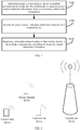
- an embodiment of this disclosure provides a sidelink power control method.
- the method may be applied to transmit power control processing for sidelink communication.
- the method may be executed by user equipment.
- the user equipment may be a terminal device.
- the terminal device may be a mobile terminal device such as a mobile phone, a tablet computer, or a wearable device.
- the terminal device may alternatively be a terminal device such as a personal computer, and the terminal device may be a terminal device used for information sending in the sidelink communication.
- the method may specifically include steps S102 to S106.
- S102 information is sent to a first terminal device in the sidelink communication, so that the first terminal device generates power control indication information based on a receiving status of the information;
- the power control indication information is received from the first terminal device.
- the first terminal device may be an individual independent terminal device, or may be a plurality of terminal devices. In other words, there may be a plurality of terminal devices used for information receiving in the sidelink communication.
- the power control indication information may be information used to instruct the information sending terminal in the sidelink communication whether to adjust a transmit power of the information sending terminal.
- the power control indication information may include related information able to instruct to adjust or control the transmit power of the terminal device in the sidelink communication.
- the power control indication information may include not only information about whether to adjust the transmit power, but also information about how to adjust the transmit power, for example, to increase or decrease the transmit power, and may also include information such as how much to be adjusted of the transmit power, such as 0.5 mW or 1 mW.
- the power control indication information is not merely used to indicate whether to adjust the transmit power.
- the power control indication information may also have other usage or functions, such as determining signal quality or determining noise in a signal. This is not limited in this embodiment of this disclosure.
- open-loop power control in the sidelink (that is, Sidelink) communication may be implemented based on an open-loop power control method in Long Term Evolution (Long Term Evolution, LTE). That is, the transmit power of the terminal device in the sidelink communication can be controlled in a centralized manner by using path loss (that is, Pathloss) between the terminal device and the network-side device.
- the open-loop power control may be a power control manner in which a sender can determine and control a transmit power of the sender, not requiring a receiver to feed back a receiving status of the information.
- the terminal device calculates a basic open-loop operation point based on a static parameter or a semi-static parameter delivered by the network-side device.
- the basic open-loop operation point may be divided into two parts: (1) a target value P 0 , indicated by a semi-static parameter, of open-loop power of the terminal device; and (2) an open-loop path loss compensation component.
- the power control process is capable of implementing open-loop power control.
- a basic formula for open-loop power control for the sidelink communication can be expressed as a formula (1).
- P min P CMAX P 0 + 10 log 10 M + ⁇ g PL
- P CMAX is a maximum transmit power of the terminal device
- M may be an allocated bandwidth ( M may be in RBs)
- PL may be a measured path loss value of a serving cell
- P 0 and ⁇ may be indicated by higher-layer parameters of P 0 and alpha, corresponding to an open-loop power target value and a compensation factor of power loss of the terminal device on the physical sidelink shared channel (Physical Sidelink Shared Channel, PSSCH), respectively.
- PSSCH Physical Sidelink Shared Channel
- open-loop power control for the sidelink communication in 5G or subsequent evolved wireless network communication can be implemented based on open-loop power control in LTE.
- closed-loop power control for the sidelink communication has not been implemented. Closed-loop power control has an unparalleled advantage over open-loop power control, for example, being more accurate in power control, and therefore closed-loop power control for the sidelink communication is a necessity for 5G or evolved wireless network communication. How to implement closed-loop power control for the sidelink communication is a problem to be resolved.
- This embodiment of this disclosure provides a mechanism for implementing closed-loop power control for the sidelink communication.
- closed-loop power control may be introduced on a basis of open-loop power control for the sidelink communication to implement further power control.
- Specific processing may include the following content: Closed-loop power control may be a power control mode that a sender controls a transmit power according to power control indication information sent by a receiver.
- a feedback control loop is required in the sidelink communication, and signal quality of a received signal is compared with expected signal quality, so as to provide the terminal device with the power control indication information indicating whether to increase or decrease the transmit power.
- the power control indication information may be implemented by using a command in wireless network communication, such as a transmit power control (Transmit power Control, TPC) command.
- TPC Transmit power Control
- the sidelink communication may include a terminal device used for information sending, and one or more first terminal devices used for information receiving.
- An information transmit power may be preset in the terminal device.
- the information transmit power may be obtained through open-loop power control for the sidelink communication, or may be obtained in another manner (for example, according to a preset protocol or based on higher-layer configuration information).
- the terminal device may send information or an information feedback request to the first terminal device through the network-side device.
- the first terminal device may collect, based on the receiving status of the information (for example, whether the information is not received due to an excessive low transmit power, or whether the information is not received due to a system failure of the first terminal device), related information about signal quality of the signal received by the first terminal device; may process the related information to obtain processed information; and may generate the power control indication information based on the processed information.
- the first terminal device may send the power control indication information to the terminal device, and the terminal device may receive the power control indication information sent by the first terminal device.
- the information transmit power of the terminal device in the sidelink communication is determined according to the power control indication information.
- a sidelink may transmit a signal or information through a radio frame.
- One subframe of the sidelink may include two consecutive timeslots and may start with an even-numbered timeslot.
- a threshold or an expected value of signal quality of the signal sent by the terminal device can be pre-configured by using a corresponding communications protocol or in a manner of an agreement between devices.
- the terminal device may analyze the power control indication information, and extract or calculate the related information about the signal quality of the signal received by the first terminal device; then, may compare the extracted or calculated information with the pre-configured threshold or expected value of the signal quality, and may determine, based on a comparison result, whether to increase the information transmit power of the terminal device (the information sending terminal) in the sidelink communication or to decrease the information transmit power of the terminal device (the information sending terminal) in the sidelink communication, or directly determine the information transmit power of the terminal device (the information sending terminal) in the sidelink communication based on the comparison result.
- a plurality of different thresholds or expected values of signal quality may be configured, for example, two, three or four thresholds or expected values. Configuration of two thresholds or expected values of signal quality is used as an example, and may be specifically as follows: The two thresholds or expected values of signal quality may be K1 and K2, and K1 ⁇ K2. If the signal quality is less than or equal to K1, the information transmit power of the terminal device (information sending terminal) in the sidelink communication is 1dBm. If the signal quality is greater than K1 and less than K2, the information transmit power of the terminal device in the sidelink communication is 2dBm.
- the terminal device may determine, according to the power control indication information, the signal quality of the signal received by the first terminal device, and determine the information transmit power of the terminal device in the sidelink communication by determining a position of the signal quality in the foregoing range. For example, if the signal quality determined according to the power control indication information is greater than K1 and less than K2, the information transmit power of the terminal device may be then set to 2dBm. In this case, the terminal device may send information or a signal at the transmit power of 2dBm.
- the terminal device may be an information sending terminal in the sidelink communication, and receives the power control indication information sent by the first terminal device acting as the information receiving terminal in the sidelink communication, so as to determine the information transmit power of the terminal device (that is, the information sending terminal) in the sidelink communication.
- the terminal device can perform closed-loop power control by using the power control indication information in the sidelink communication, so as to further adjust the transmit power of the information sending terminal in the sidelink communication. This can always ensure a relatively good reception effect for the first terminal device to receive information or a signal sent by the information sending terminal, thereby reducing power wastes and improving overall performance of the communications system.
- FIG. 3 another embodiment of this disclosure provides a sidelink power control method.
- the method may be applied to closed-loop power control processing of sidelink communication.
- the method may be executed by user equipment.
- the user equipment may be a terminal device.
- the terminal device may be a mobile terminal device such as a mobile phone, a tablet computer, or a wearable device.
- the terminal device may alternatively be a terminal device such as a personal computer, and the terminal device may be the first terminal device in the foregoing embodiment of FIG. 1 , that is, may be a terminal device used for information sending in the sidelink communication.
- the method may specifically include steps S302 to S304.
- information is received from a second terminal device in the sidelink communication.
- the second terminal device may be the terminal device in the foregoing embodiment of FIG. 1 .
- the terminal device used for information receiving is the first terminal device
- the terminal device used for information sending may be the second terminal device.
- one terminal device may be in different sidelink communication.
- Power control indication information may include not only information about whether to adjust a transmit power, but also information about how to adjust the transmit power, for example, to increase or decrease the transmit power, and may also include information such as how much to be adjusted of the transmit power and the like.
- the sidelink communication may include the second terminal device used for information sending, and one or more first terminal devices used for information receiving.
- An information transmit power may be preset in the second terminal device.
- the information transmit power may be obtained through open-loop power control for the sidelink communication, or may be obtained in another manner (for example, according to a preset protocol or based on higher-layer configuration information).
- the second terminal device may send information to the first terminal device based on the preset information transmit power through the network-side device.
- the power control indication information is sent to the second terminal device based on a receiving status of the information, so that the second terminal device determines the information transmit power of the second terminal device in the sidelink communication according to the power control indication information.
- the first terminal device may collect, based on the receiving status of the information, related information about signal quality of a signal received by the first terminal device, and may generate the power control indication information (it should be noted that the power control indication information may reflect the receiving status of the information of the first terminal device) based on the foregoing information.
- the first terminal device may send the power control indication information to the second terminal device.
- the second terminal device may determine, according to the power control indication information, the information transmit power of the second terminal device (that is, the information sending terminal in the sidelink communication) in the sidelink communication.
- the terminal device may be an information receiving terminal in the sidelink communication, and sends the power control indication information to the second terminal device acting as the information sending terminal in the sidelink communication, so that the second terminal device determines the information transmit power of the information sending terminal in the sidelink communication.
- the terminal device can perform closed-loop power control by using the power control indication information in the sidelink communication, so as to further adjust the transmit power of the information sending terminal in the sidelink communication. This can always ensure a relatively good reception effect for the first terminal device to receive information or a signal sent by the information sending terminal, thereby reducing power wastes and improving overall performance of the communications system.
- FIG. 4 another embodiment of this disclosure provides a sidelink power control method.
- the method may be applied to closed-loop power control processing of sidelink communication.
- the method may be executed by user equipment.
- the user equipment may be a terminal device
- the terminal device may be a mobile terminal device such as a mobile phone, a tablet computer, or a wearable device
- the terminal device may also be a terminal device such as a personal computer.
- the terminal device as an execution body in this embodiment, may include the first terminal device in the foregoing embodiment shown in FIG. 1 , that is, may be the terminal device used for information receiving in the sidelink communication, and the second terminal device in the foregoing embodiment shown in FIG. 2 , that is, the terminal device used for information sending in the sidelink communication.
- the method may specifically include steps S402 to S406.
- the first terminal device receives information from the second terminal device.
- the first terminal device sends target information to the second terminal device based on a receiving status of the information.
- the target information carries the power control indication information, and the target information may be one of the following information: sidelink control information SCI, a physical sidelink control channel PSCCH, and a physical sidelink shared channel PSSCH.
- the target information may be information that carries the power control indication information, and may include any one of sidelink control information (Sidelink Control Information, SCI), a physical sidelink control channel (Physical Sidelink Control Channel, PSCCH), and a physical sidelink shared channel (Physical Sidelink Shared Channel, PSSCH).
- SCI Sidelink Control Information
- PSCCH Physical Sidelink Control Channel
- PSSCH Physical Sidelink Shared Channel
- the target information is not limited to the foregoing three types, and may further include a plurality of types. This is not limited in this embodiment of this disclosure.
- the power control indication information may include one or a combination of the following: a hybrid automatic repeat request acknowledgment (Hybrid Automatic Repeat reQuest Acknowledgement, HARQ ACK)/hybrid automatic repeat request negative acknowledgment (Hybrid Automatic Repeat reQuest Negative Acknowledgment, HARQ NACK), a channel quality indicator (Channel Quality Indicator, CQI), a signal-to-noise ratio (Signal to Interference plus Noise Ratio, SINR), and a block error ratio (Block Error Ratio, BLER).
- content included in the power control indication information is not limited to the foregoing four types, and may also include a plurality of types, which may be specifically set based on an actual condition. This is not limited in this embodiment of this disclosure.
- the first terminal device may collect, based on a receiving status of the information, one or more pieces of information of the first terminal device: the signal quality information indicator CQI, the signal-to-noise ratio SINR, the block error rate BLER, and the hybrid automatic repeat request acknowledgment/negative acknowledgment HARQ ACK/NACK; may generate the power control indication information based on the collected information; and may include the power control indication information in the SCI, PSCCH or PSSCH, and send the power control indication information to the second terminal device by using the SCI, PSCCH or PSSCH.
- the second terminal device determines the information transmit power of the second terminal device in the sidelink communication according to the power control indication information.
- the second terminal device may determine, based on the information in the power control indication information (that is, one or more pieces of information in the CQI, SINR, BLER and HARQ ACK/NACK), whether to adjust the information transmit power of the second terminal device in the sidelink communication. If adjustment is not required, processing in the foregoing S402 to S406 may be cyclically performed. If adjustment is required, a magnitude of transmit power adjustment for the second terminal device may be determined according to the power control indication information, so as to adjust the transmit power of the second terminal device based on the determined magnitude, to obtain the adjusted transmit power. In this case, the second terminal device may send information or a signal based on the adjusted transmit power. For a specific processing process, reference may also be made to related content of S104.
- the information transmit power of the second terminal device in the sidelink communication may be determined in different manners.
- the following provides three optional processing manners, which may specifically include the following content: Manner 1: Determine the information transmit power of the second terminal device in the sidelink communication based on a quantity of pieces of the received power control indication information and a total quantity of the second terminal devices and the first terminal devices.
- an actual application scenario is used as an example.
- a vehicle queue that is, Platooning
- the vehicle queue includes six vehicles, a terminal device used for information sending and receiving is disposed in each vehicle, and the six vehicles may include a first vehicle.
- the first vehicle may be the front vehicle (which may also be referred to as a head vehicle) in the vehicle queue, or may be the last vehicle in the vehicle queue, or may be a vehicle between the front vehicle and the last vehicle.
- an initial information transmit power (the initial transmit power may be obtained by means of open-loop power control for the sidelink communication or obtained in another manner (for example, according to a preset protocol or based on higher-layer configuration information)) for the sidelink communication may be preset in the terminal device (that is, the second terminal device) of the first vehicle.
- the first vehicle may send information to another vehicle by using the terminal device of the first vehicle. If the information can be correctly received by the another vehicle, one piece of power control indication information (or may be referred to as response information) may be fed back to the first vehicle.
- the information transmit power of the second terminal device (that is, the first vehicle) in the sidelink communication may be calculated by using the three pieces of power control indication information and a total quantity of vehicles in the vehicle queue (that is, the total quantity of the second terminal devices and the first terminal devices (that is, the terminal devices in the vehicles other than the first vehicle).
- a total quantity of vehicles in the vehicle queue that is, the total quantity of the second terminal devices and the first terminal devices (that is, the terminal devices in the vehicles other than the first vehicle.
- the first vehicle receives three pieces of power control indication information in total, and the total quantity of vehicles in the vehicle queue is 6.
- the power control indication information may include a plurality of types of information such as the HARQ ACK/NACK, CQI, SINR and BLER, and different information may be processed in different manners. Therefore, the following describes in detail the foregoing cases including different information. For details, reference may be made to the following manner 2 and manner 3.
- the power control indication information may include the HARQ ACK/NACK.
- processing in S406 may be: determining the information transmit power of the second terminal device in the sidelink communication based on a first threshold and a proportion of the HARQ NACKs to a sum of the HARQ ACKs and HARQ NACKs.
- the first threshold may be determined based on higher-layer configuration information, or determined according to a preset protocol, or predefined.
- the higher-layer configuration information may be of a communications layer higher than the second terminal device in the sidelink communication, which may be specifically a network-side device (such as a base station), or may be another terminal device, or the like. Predefining may be specifying or setting based on an actual condition.
- the initial information transmit power in the sidelink communication may be preset on the second terminal device in the sidelink communication (the initial transmit power may be obtained by means of open-loop power control for the sidelink communication, or may be obtained in another manner).
- the second terminal device may send information to the first terminal device in the side-link communication. After receiving the information, the first terminal device may send a HARQ ACK or HARQ NACK to the second terminal device.
- the second terminal device may collect statistics about a quantity of received HARQ NACKs, a quantity of received HARQ ACKs, and the sum of HARQ NACKs and HARQ ACKs, and then calculate the proportion of the quantity of HARQ NACKs to the sum of HARQ ACKs and HARQ NACKs, that is, NACK/(NACK+ACK).
- a first threshold may be preset in the second terminal device.
- the first threshold may be an expected value, an optimal value, or the like that is determined based on an actual condition.
- the first threshold may include one value, or may include a plurality of values, for example, two, three, or four values, and a corresponding transmit power calculation method or calculation rule may be separately set based on a quantity of first thresholds.
- the second terminal device may compare a value of the obtained proportion with the first threshold, and may calculate a corresponding information transmit power of the second terminal device in the sidelink communication by using a corresponding transmit power calculation method or calculation rule.
- the information transmit power 1dBm of the second terminal device in the sidelink communication may be obtained by using the foregoing transmit power calculation method or calculation rule.
- the first threshold includes two values.
- the first threshold is not limited to a case in which two values are included, and may alternatively include more than two values, which may be specifically set based on an actual condition. This is not limited in this embodiment of this disclosure.
- the power control indication information may include the CQI
- processing of S406 may be: determining the information transmit power of the second terminal device in the sidelink communication based on to a magnitude relationship between the CQI and an expected CQI.
- the expected CQI may be determined based on higher-layer configuration information, or determined according to a preset protocol, or predefined.
- the initial information transmit power in the sidelink communication may be preset on the second terminal device in the sidelink communication (the initial transmit power may be obtained by means of open-loop power control for the sidelink communication, or may be obtained in another manner).
- the second terminal device may send information to the first terminal device in the side-link communication.
- the first terminal device may send CQI information to the second terminal device.
- the second terminal device may perform independent closed-loop power control on different resource pools or bandwidth parts (Bandwidth Part, BWP), so as to implement independent power control in the side-link communication.
- the expected CQI may be preset.
- the expected CQI may be an expected value, an optimal value, or the like that is determined based on an actual condition.
- the expected CQI may include one value, or may include a plurality of values, for example, two, three, or four values.
- a corresponding transmit power calculation method or calculation rule may be set based on a quantity of expected CQIs. Then, the second terminal device may compare the obtained CQI information with the expected CQI, and may calculate, based on the comparison result, a corresponding information transmit power of the second terminal device in the sidelink communication by using the corresponding transmit power calculation method or calculation rule.
- the expected CQI includes two values, which may be a and b
- the transmit power calculation method or calculation rule may be set as follows: If the received CQI satisfies a specified value range, that is, [a, b], the second terminal device in the sidelink communication does not need to perform closed-loop power control; if the received CQI is less than a, it indicates that the channel quality in the current sidelink communication is poor, and in this case, the transmit power of the second terminal device in the sidelink communication may be properly increased; and if the received CQI is greater than b, it indicates that the channel quality in the current sidelink communication is relatively good, and in this case, the transmit power of the second terminal device in the sidelink communication may be properly decreased.
- a specified value range that is, [a, b]
- the expected CQI includes two values.
- the expected CQI is not limited to a case in which two values are included, and may alternatively include more than two values, which may be specifically set based on an actual condition. This is not limited in this embodiment of this disclosure.
- the terminal device may be an information sending terminal in the sidelink communication, and receives the power control indication information sent by the first terminal device acting as the information receiving terminal in the sidelink communication, so as to determine the information transmit power of the terminal device (that is, the information sending terminal) in the sidelink communication.
- the terminal device can perform closed-loop power control by using the power control indication information in the sidelink communication, so as to further adjust the transmit power of the information sending terminal in the sidelink communication. This can always ensure a relatively good reception effect for the first terminal device to receive information or a signal sent by the information sending terminal, thereby reducing power wastes and improving overall performance of the communications system.
- FIG. 5 still another embodiment of this disclosure provides a sidelink power control method.
- the method may be applied to closed-loop power control processing of sidelink communication.
- the method may be executed by user equipment.
- the user equipment may be a terminal device
- the terminal device may be a mobile terminal device such as a mobile phone, a tablet computer, or a wearable device
- the terminal device may also be a terminal device such as a personal computer.
- the terminal device as an execution body in this embodiment, may include the first terminal device in the foregoing embodiment shown in FIG. 1 , that is, may be the terminal device used for information receiving in the sidelink communication, and the second terminal device in the foregoing embodiment shown in FIG. 2 , that is, the terminal device used for information sending in the sidelink communication.
- the method may specifically include steps S502 to S506.
- the first terminal device receives information from the second terminal device.
- the first terminal device sends target information to the second terminal device based on a receiving status of the information.
- the target information carries the power control indication information, and the target information is one of the following information: sidelink control information SCI, a physical sidelink control channel PSCCH, and a physical sidelink shared channel PSSCH.
- the power control indication information includes a power change parameter.
- the power change parameter may be used to indicate whether to adjust an information transmit power of the second terminal device in the sidelink communication, how to adjust the information transmit power, and how much to be adjusted, and the like.
- the first terminal device may compare a receive power of the first terminal device with a preset receive power threshold (which may be specifically a value, a value range, or the like, which is not limited in this embodiment of this disclosure), and may determine, based on a comparison result, whether to adjust the information transmit power of the second terminal device in the sidelink communication. If adjustment is required, the first terminal device may obtain a corresponding power change parameter, use the power change parameter as the power control indication information, include the power control indication information in SCI, a PSCCH, or a PSSCH, and send the power control indication information to the second terminal device.
- a preset receive power threshold which may be specifically a value, a value range, or the like, which is not limited in this embodiment of this disclosure
- the power change parameter is R1; if the receive power of the first terminal device is less than a preset receive power threshold, the power change parameter is R2 or the like. Values of R1 and R2 may be determined based on an actual condition, for example, R2 is a positive number and R1 is a negative number.
- the power control indication information may be carried in the SCI, the PSCCH, or the PSSCH in the foregoing manner, or may be sent in an manner other than the foregoing manner, for example, the first terminal device may send the power control indication information to the second terminal device through another channel or path. This is not limited in this embodiment of this disclosure.
- a value of the power change parameter is a difference between the preset receive power threshold of the first terminal device and the receive power of the first terminal device.
- the preset receive power threshold of the first terminal device is determined based on higher-layer configuration information, or determined according to a preset protocol, or predefined. With the receive power corresponding to the preset receive power threshold of the first terminal device, a relatively good reception effect can be ensured for the first terminal device.
- the difference may be calculated as follows:
- the value of the power change parameter is equal to the preset receive power threshold of the first terminal device minus the receive power of the first terminal device.
- the second terminal device adjusts a current transmit power based on the value of the power change parameter to obtain the information transmit power of the second terminal device in the sidelink communication.
- the second terminal device may receive the power control indication information sent by the first terminal device by using the SCI, PSCCH, PSSCH, or the like. Then, the second terminal device may analyze the power control indication information, and may extract the power change parameter from the power control indication information. The second terminal device may adjust the current transmit power of the second terminal device to ensure that the first terminal device in the side-link communication has a better information reception effect. Specifically, the current transmit power of the second terminal device may be increased or decreased by the value of the power change parameter.
- Whether to increase or decrease may be determined based on a relationship between the receive power of the first terminal device and the preset receive power threshold of the first terminal device, or may be determined based on a positive or negative value obtained by subtracting the receive power of the first terminal device from the preset receive power threshold of the first terminal device. For example, if the receive power of the first terminal device is less than the preset receive power threshold of the first terminal device, the current transmit power of the second terminal device may be increased by the value of the power change parameter; if the receive power of the first terminal device is greater than the preset receive power threshold of the first terminal device, the current transmit power of the second terminal device may be decreased by the value of the power change parameter.
- the receive power of the first terminal device is 1dBm
- the preset receive power threshold, set in the sidelink communication, of the first terminal device is 5dBm
- the information transmit power of the second terminal device in the sidelink communication is the current transmit power of the second terminal device plus the power change parameter 4dBm.
- the second terminal device may send information, a signal, or the like at the transmit power obtained by increasing 4dBm.
- the second terminal device may have a plurality of power control processes, and each power control process may correspond to one transmit power.
- each power control process has one power change parameter corresponding to the power control process, and then a specific processing process of the foregoing S506 may include the following steps 1 and 2.
- Step 1 Determine, based on a value of the power change parameter corresponding to each power control process, a transmit power corresponding to the power control process.
- the transmit power corresponding to the power control process may be calculated based on a value of the power change parameter corresponding to the power control process by performing the foregoing processing process. For details, reference may be made to the foregoing related content. Details are not described herein again.
- Step 2 Determine the information transmit power of the terminal device according to a power determining rule and based on transmit powers corresponding to the plurality of power control processes, where the power determining rule is used to select one or more transmit powers from the transmit powers corresponding to the plurality of power control processes, so as to determine the information transmit power of the second terminal device in the sidelink communication.
- the processing manner in the foregoing step 2 may include a plurality of manners.
- the following provides two feasible processing manners, which may specifically include:
- each power control process in the second terminal device in the sidelink communication is in a mapping association relationship with a bandwidth part BWP and a resource pool. With the mapping association relationship, each power control process in the second terminal device in the sidelink communication has an actual carrier.
- a maximum bandwidth of 400MHz can be supported, and a value of the bandwidth is far greater than a maximum bandwidth of 20 MHz in LTE network communication. Therefore, larger system and user throughputs can be supported in 5G network communication.
- supporting the bandwidth of 400MHz is a great challenge to the terminal devices.
- the bandwidth of 400MHz is not easy to implement on low-cost terminal devices. Therefore, 5G network communication also supports a dynamic and flexible bandwidth allocation mechanism.
- the bandwidth may be divided into a plurality of parts (that is, BWP) to support narrowband terminal devices or energy-efficient terminal devices in accessing the communications networks.
- BWP-related design conclusions in 5G network communication are as follows:
- the terminal device may be an information sending terminal in the sidelink communication, and receives the power control indication information sent by the first terminal device acting as the information receiving terminal in the sidelink communication, so as to determine the information transmit power of the terminal device (that is, the information sending terminal) in the sidelink communication.
- the terminal device can perform closed-loop power control by using the power control indication information in the sidelink communication, so as to further adjust the transmit power of the information sending terminal in the sidelink communication. This can always ensure a relatively good reception effect for the first terminal device to receive information or a signal sent by the information sending terminal, thereby reducing power wastes and improving overall performance of the communications system.
- an embodiment of this disclosure further provides a terminal device, as shown in FIG. 6 .
- the terminal device may be the second terminal device in the foregoing embodiment.
- the terminal device may include an information sending module 601, an information receiving module 602, and a power adjustment module 603.
- the information sending module 601 is configured to send information to a first terminal device in sidelink communication, so that the first terminal device generates power control indication information based on a receiving status of the information;
- the information receiving module 602 is configured to receive the power control indication information from the first terminal device.
- the power adjustment module 603 is configured to determine an information transmit power of the terminal device in the sidelink communication according to the power control indication information.
- the information receiving module 602 is configured to receive target information from the first terminal device, the target information carries the power control indication information, and the target information is one of the following information: sidelink control information SCI, a physical sidelink control channel PSCCH, and a physical sidelink shared channel PSSCH.
- the power control indication information includes one or a combination of the following: a hybrid automatic repeat request acknowledgment/negative acknowledgment HARQ ACK/NACK, a channel quality indicator CQI, a signal-to-noise ratio SINR, and a block error rate BLER.
- the power adjustment module 603 is configured to determine the information transmit power of the terminal device in the sidelink communication based on a quantity of pieces of the received power control indication information and a total quantity of the terminal devices and the first terminal devices.
- the power control indication information includes a HARQ ACK/NACK.
- the power adjustment module 603 is configured to determine, based on a first threshold and a proportion of the HARQ NACKs to a sum of the HARQ ACKs and the HARQ NACKs, the information transmit power of the terminal device in the sidelink communication, where the first threshold is determined based on higher-layer configuration information, or determined according to a preset protocol, or predefined.
- the power control indication information includes a CQI.
- the power adjustment module 603 is configured to determine, based on a magnitude relationship between the CQI and an expected CQI, the information transmit power of the terminal device in the sidelink communication, where the expected CQI is determined based on higher-layer configuration information, or determined according to a preset protocol, or predefined.
- the power control indication information includes a power change parameter.
- the power adjustment module 603 is configured to adjust a current transmit power based on a value of the power change parameter to obtain the information transmit power of the terminal device in the sidelink communication.
- the value of the power change parameter is a difference between a preset receive power threshold of the first terminal device and a receive power of the first terminal device, and the preset receive power threshold of the first terminal device is determined based on higher-layer configuration information, or determined according to a preset protocol, or predefined.
- the terminal device includes a plurality of power control processes.
- the power adjustment module 603 is configured to: determine, based on a value of the power change parameter corresponding to each power control process, a transmit power corresponding to the power control process; and determine the information transmit power of the terminal device according to a power determining rule and based on transmit powers corresponding to the plurality of power control processes, where the power determining rule is used to select one or more transmit powers from the transmit powers corresponding to the plurality of power control processes, so as to determine the information transmit power of the terminal device.
- each power control process is in a mapping association relationship with a bandwidth portion BWP and a resource pool; a preset receive power threshold of the first terminal device on a first power control process is determined by a BWP and a resource pool that are in a mapping association relationship with the first power control process; and the first power control process is one of the plurality of power control processes.
- the terminal device may be an information sending terminal in the sidelink communication, and receives the power control indication information sent by the first terminal device acting as the information receiving terminal in the sidelink communication, so as to determine the information transmit power of the terminal device (that is, the information sending terminal) in the sidelink communication.
- the terminal device can perform closed-loop power control by using the power control indication information in the sidelink communication, so as to further adjust the transmit power of the information sending terminal in the sidelink communication. This can always ensure a relatively good reception effect for the first terminal device to receive information or a signal sent by the information sending terminal, thereby reducing power wastes and improving overall performance of the communications system.
- an embodiment of this disclosure further provides a terminal device, as shown in FIG. 7 .
- the terminal device may be the first terminal device in the foregoing embodiment.
- the terminal device may include an information receiving module 701 and an information sending module 702.
- the information receiving module 701 is configured to receive information from a second terminal device in sidelink communication.
- the information sending module 702 is configured to send power control indication information to the second terminal device based on a receiving status of the information, so that the second terminal device determines an information transmit power of the second terminal device in the sidelink communication according to the power control indication information.
- the information sending module 702 is configured to send target information to the second terminal device.
- the target information carries the power control indication information, and the target information is one of the following information: sidelink control information SCI, a physical sidelink control channel PSCCH, and a physical sidelink shared channel PSSCH.
- the power control indication information includes one or a combination of the following: a hybrid automatic repeat request acknowledgment/negative acknowledgment HARQ ACK/NACK, a channel quality indicator CQI, a signal-to-noise ratio SINR, and a block error rate BLER.
- the power control indication information includes a power change parameter, and the power change parameter is used to determine the information transmit power of the second terminal device in the sidelink communication.
- the terminal device may be an information receiving terminal in the sidelink communication, and sends the power control indication information to the second terminal device acting as the information sending terminal in the sidelink communication, so that the second terminal device determines the information transmit power of the information sending terminal in the sidelink communication.
- the terminal device can perform closed-loop power control by using the power control indication information in the sidelink communication, so as to further adjust the transmit power of the information sending terminal in the sidelink communication. This can always ensure a relatively good reception effect for the first terminal device to receive information or a signal sent by the information sending terminal, thereby reducing power wastes and improving overall performance of the communications system.
- FIG 8 is a block diagram of a terminal device according to another embodiment of this disclosure.
- the terminal device 800 shown in FIG. 8 includes at least one processor 801, a memory 802, at least one network interface 804, and a user interface 803.
- the components of the terminal device 800 are coupled together by using a bus system 805.
- the bus system 805 is configured to implement connection communication between these components.
- the bus system 805 may include not only a data bus but also a power supply bus, a control bus, and a status signal bus. However, for clear description, various buses in FIG. 8 are marked as the bus system 805.
- the user interface 803 may include display, a keyboard, or a pointing device (for example, a mouse, a trackball (trackball), a touch panel, or a touchscreen).
- a pointing device for example, a mouse, a trackball (trackball), a touch panel, or a touchscreen.
- the memory 802 in this embodiment of this disclosure may be a volatile memory or a non-volatile memory, or may include both a volatile memory and a non-volatile memory.
- the non-volatile memory may be a read-only memory (Read-Only Memory, ROM), a programmable read-only memory (Programmable ROM, PROM), an erasable programmable read-only memory (Erasable PROM, EPROM), an electrically erasable programmable read-only memory (Electrically EPROM, EEPROM), or a flash memory.
- the volatile memory may be a random access memory (Random Access Memory, RAM), which is used as an external cache.
- RAM random access memory
- SRAM static random access memory
- DRAM dynamic random access memory
- DRAM synchronous dynamic random access memory
- SDRAM double data rate synchronous dynamic random access memory
- Enhanced SDRAM ESDRAM
- Synchlink DRAM SLDRAM
- Direct Rambus RAM Direct Rambus RAM
- the memory 802 stores the following elements: executable modules or data structures, or a subset thereof, or an extended set thereof: an operating system 8021 and an application program 8022.
- the operating system 8021 includes various system programs, such as a framework layer, a kernel library layer, and a driver layer, for implementing various basic services and processing hardware-based tasks.
- the application program 8022 includes various application programs, such as a media player (Media Player), and a browser (Browser), which are used to implement various application services.
- a program for implementing the method of the embodiments of this disclosure may be included in the application program 8022.
- the terminal device 800 further includes a computer program stored in the memory 805 and configured to run on the processor 801.
- the computer program implements the following steps:
- the methods disclosed in the embodiments of this disclosure are applicable to the processor 801, or are implemented by the processor 801.
- the processor 801 may be an integrated circuit chip with a signal processing capability. During implementation, the steps of the method can be completed by hardware integrated logic circuits in the processor 801 or instructions in the form of software.
- the processor 801 may be a general-purpose processor, a digital signal processor (Digital Signal Processor, DSP), an application-specific integrated circuit (Application Specific Integrated Circuit, ASIC), a field programmable gate array (Field Programmable Gate Array, FPGA) or another programmable logical device, a discrete gate or transistor logical device, or a discrete hardware component.
- DSP Digital Signal Processor
- ASIC Application Specific Integrated Circuit
- FPGA Field Programmable Gate Array
- the processor 801 may implement or execute the methods, steps, and logical block diagrams disclosed in the embodiments of this disclosure.
- the general-purpose processor may be a microprocessor, or the processor may also be any conventional processor or the like.
- the steps of the methods disclosed with reference to the embodiments of this disclosure may be directly executed and completed by a hardware decoding processor, or executed and completed by a combination of hardware and software modules in a decoding processor.
- the software module may be located in a computer-readable storage medium mature in the art, such as a random access memory, a flash memory, a read-only memory, a programmable read-only memory, or an electrically erasable programmable memory, or a register.
- the computer-readable storage medium is located in the memory 802, and the processor 801 fetches information in the memory 802 and completes the steps of the foregoing method in combination with its hardware.
- the computer-readable storage medium stores a computer program, and the computer program is executed by the processor 801, the steps in the selection method embodiment of the network unit are implemented.
- the embodiments described in this disclosure may be implemented by hardware, software, firmware, middleware, microcode, or a combination thereof.
- the processing unit can be implemented in one or more application-specific integrated circuits (Application Specific Integrated Circuits, ASIC), digital signal processors (Digital Signal Processing, DSP), digital signal processing devices (DSP Device, DSPD), programmable logic devices (Programmable Logic Device, PLD), field-programmable gate arrays (Field-Programmable Gate Array, FPGA), general-purpose processors, microcontrollers, microprocessors, other electronic units for performing the functions described in this disclosure, or a combination thereof.
- ASIC Application Specific Integrated Circuits
- DSP Digital Signal Processing
- DSP Device digital signal processing devices
- PLD programmable logic devices
- FPGA field-programmable gate array
- general-purpose processors microcontrollers, microprocessors, other electronic units for performing the functions described in this disclosure, or a combination thereof.
- the techniques described in the embodiments of this disclosure may be implemented by modules (for example, procedures or functions) that perform the functions described in the embodiments of this disclosure.
- Software code may be stored in the memory and executed by the processor.
- the memory may be implemented inside or outside the processor.
- the receiving the power control indication information from the first terminal device includes: receiving target information from the first terminal device, where the target information carries the power control indication information, and the target information is one of the following information: sidelink control information SCI, a physical sidelink control channel PSCCH, and a physical sidelink shared channel PSSCH.
- the power control indication information includes one or a combination of the following: a hybrid automatic repeat request acknowledgment/negative acknowledgment HARQ ACK/NACK, a channel quality indicator CQI, a signal-to-noise ratio SINR, and a block error rate BLER.
- the determining an information transmit power of the terminal device in the sidelink communication according to the power control indication information includes: determining the information transmit power of the terminal device in the sidelink communication based on a quantity of pieces of the received power control indication information and a total quantity of the terminal devices and the first terminal devices.
- the power control indication information includes the HARQ ACK/NACK.
- the determining an information transmit power of the terminal device in the sidelink communication according to the power control indication information includes: determining, based on a first threshold and a proportion of the HARQ NACKs to a sum of the HARQ ACKs and the HARQ NACKs, the information transmit power of the terminal device in the sidelink communication, where the first threshold is determined based on higher-layer configuration information, or determined according to a preset protocol, or predefined.
- the power control indication information includes the CQI.
- the determining an information transmit power of the terminal device in the sidelink communication according to the power control indication information includes: determining, based on a magnitude relationship between the CQI and an expected CQI, the information transmit power of the terminal device in the sidelink communication, where the expected CQI is determined based on higher-layer configuration information, or determined according to a preset protocol, or predefined.
- the power control indication information includes a power change parameter.
- the determining an information transmit power of the terminal device in the sidelink communication according to the power control indication information includes: adjusting a current transmit power based on a value of the power change parameter to obtain the information transmit power of the terminal device in the sidelink communication.
- the value of the power change parameter is a difference between a preset receive power threshold of the first terminal device and a receive power of the first terminal device, and the preset receive power threshold of the first terminal device is determined based on higher-layer configuration information, or determined according to a preset protocol, or predefined.
- the terminal device includes a plurality of power control processes.
- the adjusting a current transmit power based on a value of the power change parameter to obtain the information transmit power of the terminal device in the sidelink communication includes:
- each power control process is in a mapping association relationship with a bandwidth portion BWP and a resource pool.
- a preset receive power threshold of the first terminal device on a first power control process is determined by a BWP and a resource pool that are in a mapping association relationship with the first power control process.
- the first power control process is one of the plurality of power control processes.
- the terminal device 800 is capable of implementing each process implemented by the terminal device in the foregoing embodiments. To avoid repetition, details are not described herein again.
- the terminal device may be an information sending terminal in the sidelink communication, and receives the power control indication information sent by the first terminal device acting as the information receiving terminal in the sidelink communication, so as to determine the information transmit power of the terminal device (that is, the information sending terminal) in the sidelink communication.
- the terminal device can perform closed-loop power control by using the power control indication information in the sidelink communication, so as to further adjust the transmit power of the information sending terminal in the sidelink communication. This can always ensure a relatively good reception effect for the first terminal device to receive information or a signal sent by the information sending terminal, thereby reducing power wastes and improving overall performance of the communications system.
- FIG 9 is a block diagram of a terminal device according to another embodiment of this disclosure.
- the terminal device 900 shown in FIG. 9 includes at least one processor 901, a memory 902, at least one network interface 904, and a user interface 903.
- the components of the terminal device 900 are coupled together by using a bus system 905.
- the bus system 905 is configured to implement connection communication between these components.
- the bus system 905 may include not only a data bus but also a power supply bus, a control bus, and a status signal bus. However, for clear description, various buses in FIG. 9 are marked as the bus system 905.
- the user interface 903 may include a display, a keyboard, a click device (for example, a mouse or a trackball (trackball)), a touch board, or a touchscreen.
- a click device for example, a mouse or a trackball (trackball)
- a touch board for example, a touch screen, or a touchscreen.
- the memory 902 in this embodiment of this disclosure may be a volatile memory or a non-volatile memory, or may include both a volatile memory and a non-volatile memory.
- the non-volatile memory may be a read-only memory (Read-Only Memory, ROM), a programmable read-only memory (Programmable ROM, PROM), an erasable programmable read-only memory (Erasable PROM, EPROM), an electrically erasable programmable read-only memory (Electrically EPROM, EEPROM), or a flash memory.
- the volatile memory may be a random access memory (Random Access Memory, RAM), which is used as an external cache.
- RAM random access memory
- SRAM static random access memory
- DRAM dynamic random access memory
- DRAM synchronous dynamic random access memory
- SDRAM double data rate synchronous dynamic random access memory
- Enhanced SDRAM ESDRAM
- Synchlink DRAM SLDRAM
- Direct Rambus RAM Direct Rambus RAM
- the memory 902 stores the following elements: an executable module or a data structure, or a subset thereof, or an extended set thereof: an operating system 9021 and an application program 9022.
- the operating system 9021 includes various system programs, such as a framework layer, a kernel library layer, and a driver layer, which are used to implement various basic services and process hardware-based tasks.
- the application program 9022 includes various application programs, such as a media player (Media Player), and a browser (Browser), which are used to implement various application services.
- a program that implements the methods of the embodiments of this disclosure may be included in the application program 9022.
- the terminal device 900 further includes a computer program stored in the memory 905 and configured to run on the processor 901.
- the computer program implements the following steps:
- the methods disclosed in the embodiments of this disclosure are applicable to the processor 901, or are implemented by the processor 901.
- the processor 901 may be an integrated circuit chip with a signal processing capability. During implementation, the steps of the methods may be implemented by an integrated logical circuit of hardware in the processor 901, or by using a software instruction.
- the processor 901 may be a general-purpose processor, a digital signal processor (Digital Signal Processor, DSP), an application-specific integrated circuit (Application Specific Integrated Circuit, ASIC), a field programmable gate array (Field Programmable Gate Array, FPGA) or another programmable logical device, a discrete gate or transistor logical device, or a discrete hardware component.
- DSP Digital Signal Processor
- ASIC Application Specific Integrated Circuit
- FPGA Field Programmable Gate Array
- the processor 901 may implement or execute the methods, steps, and logical block diagrams disclosed in the embodiments of this disclosure.
- the general-purpose processor may be a microprocessor, or the processor may also be any conventional processor or the like.
- the steps of the methods disclosed with reference to the embodiments of this disclosure may be directly implemented by a hardware decoding processor, or may be implemented by a combination of hardware and software modules in a decoding processor.
- the software module may be located in a computer-readable storage medium that is mature in the art, such as a random access memory, a flash memory, a read-only memory, a programmable read-only memory, or an electrically erasable programmable memory, or a register.
- the computer-readable storage medium is located in the memory 902, and the processor 901 reads information in the memory 902 and implements, in combination with its hardware, the steps of the foregoing methods. Specifically, the computer-readable storage medium stores a computer program, and the computer program is executed by the processor 901 to implement the steps of the selection method embodiments of the network unit.
- processing units can be implemented in one or more application specific integrated circuits (Application Specific Integrated Circuits, ASIC), digital signal processors (Digital Signal Processing, DSP), digital signal processing devices (DSP Device, DSPD), programmable logic devices (Programmable Logic Device, PLD), field-programmable gate arrays (Field-Programmable Gate Array, FPGA), general-purpose processors, microcontrollers, microprocessors, other electronic units for performing the functions described in this disclosure, or a combination thereof.
- ASIC Application Specific Integrated Circuits
- DSP Digital Signal Processing
- DSP Device digital signal processing devices
- PLD programmable logic devices
- FPGA field-programmable gate array
- general-purpose processors microcontrollers, microprocessors, other electronic units for performing the functions described in this disclosure, or a combination thereof.
- the techniques described in the embodiments of this disclosure may be implemented by modules (such as processes and functions) that perform the functions described in the embodiments of this disclosure.
- Software code may be stored in the memory and executed by the processor.
- the memory may be implemented inside or outside the processor.
- the sending the power control indication information to the second terminal device includes: sending target information to the second terminal device, where the target information carries the power control indication information, and the target information is one of the following information: sidelink control information SCI, a physical sidelink control channel PSCCH, and a physical sidelink shared channel PSSCH.
- the power control indication information includes one or a combination of the following: a hybrid automatic repeat request acknowledgment/negative acknowledgment HARQ ACK/NACK, a channel quality indicator CQI, a signal-to-noise ratio SINR, and a block error rate BLER.
- the power control indication information includes a power change parameter, and the power change parameter is used to determine the information transmit power of the second terminal device in the sidelink communication.
- the terminal device 900 is capable of implementing each process implemented by the terminal device in the foregoing embodiments. To avoid repetition, details are not described herein again.
- the terminal device may be an information receiving terminal in the sidelink communication, and sends the power control indication information to the second terminal device acting as the information sending terminal in the sidelink communication, so that the second terminal device determines the information transmit power of the information sending terminal in the sidelink communication.
- the information transmit power of the information sending terminal in the sidelink communication can be accurately controlled by using the power control indication information fed back by the information receiving terminal. This can always ensure a relatively good reception effect for the first terminal device to receive information or a signal sent by the information sending terminal, to implement closed-loop power control for the sidelink communication, thereby improving an information or signal reception effect of the information receiving terminal.
- an embodiment of this disclosure further provides a computer-readable storage medium.
- the computer-readable storage medium stores one or more programs.
- the one or more programs When being executed by the terminal device that includes a plurality of application programs to perform the processing process shown in FIG. 1, FIG. 2 , FIG. 4 , and FIG. 5 , the one or more programs enable the terminal device to perform the following operations:
- the receiving the power control indication information from the first terminal device includes: receiving target information from the first terminal device, where the target information carries the power control indication information, and the target information is one of the following information: sidelink control information SCI, a physical sidelink control channel PSCCH, and a physical sidelink shared channel PSSCH.
- the power control indication information includes one or a combination of the following: a hybrid automatic repeat request acknowledgment/negative acknowledgment HARQ ACK/NACK, a channel quality indicator CQI, a signal-to-noise ratio SINR, and a block error rate BLER.
- the determining an information transmit power of the terminal device in the sidelink communication according to the power control indication information includes: determining the information transmit power of the terminal device in the sidelink communication based on a quantity of pieces of the received power control indication information and a total quantity of the terminal devices and the first terminal devices.
- the power control indication information includes the HARQ ACK/NACK.
- the determining an information transmit power of the terminal device in the sidelink communication according to the power control indication information includes: determining, based on a first threshold and a proportion of the HARQ NACKs to a sum of the HARQ ACKs and the HARQ NACKs, the information transmit power of the terminal device in the sidelink communication, where the first threshold is determined based on higher-layer configuration information, or determined according to a preset protocol, or predefined.
- the power control indication information includes the CQI.
- the determining an information transmit power of the terminal device in the sidelink communication according to the power control indication information includes: determining, based on a magnitude relationship between the CQI and an expected CQI, the information transmit power of the terminal device in the sidelink communication, where the expected CQI is determined based on higher-layer configuration information, or determined according to a preset protocol, or predefined.
- the power control indication information includes a power change parameter.
- the determining an information transmit power of the terminal device in the sidelink communication according to the power control indication information includes: adjusting a current transmit power based on a value of the power change parameter to obtain the information transmit power of the terminal device in the sidelink communication.
- the value of the power change parameter is a difference between a preset receive power threshold of the first terminal device and a receive power of the first terminal device, and the preset receive power threshold of the first terminal device is determined based on higher-layer configuration information, or determined according to a preset protocol, or predefined.
- the terminal device includes a plurality of power control processes.
- the adjusting a current transmit power based on a value of the power change parameter to obtain the information transmit power of the terminal device in the sidelink communication includes:
- each power control process is in a mapping association relationship with a bandwidth portion BWP and a resource pool.
- a preset receive power threshold of the first terminal device on a first power control process is determined by a BWP and a resource pool that are in a mapping association relationship with the first power control process.
- the first power control process is one of the plurality of power control processes.
- the computer-readable storage medium stores one or more programs.
- the one or more programs When being executed by the terminal device that includes a plurality of application programs to perform the processing process shown in FIG. 3 to FIG. 5 , the one or more programs enable the terminal device to perform the following operations:
- the sending the power control indication information to the second terminal device includes: sending target information to the second terminal device, where the target information carries the power control indication information, and the target information is one of the following information: sidelink control information SCI, a physical sidelink control channel PSCCH, and a physical sidelink shared channel PSSCH.
- the power control indication information includes one or a combination of the following: a hybrid automatic repeat request acknowledgment/negative acknowledgment HARQ ACK/NACK, a channel quality indicator CQI, a signal-to-noise ratio SINR, and a block error rate BLER.
- the power control indication information includes a power change parameter, and the power change parameter is used to determine the information transmit power of the second terminal device in the sidelink communication.
- the information sending terminal in the sidelink communication receives the power control indication information sent by the first terminal device acting as the information receiving terminal in the sidelink communication, so as to determine the information transmit power of the terminal device (that is, the information sending terminal) in the sidelink communication.
- the terminal device can perform closed-loop power control by using the power control indication information in the sidelink communication, so as to further adjust the transmit power of the information sending terminal in the sidelink communication. This can always ensure a relatively good reception effect for the first terminal device to receive information or a signal sent by the information sending terminal, thereby reducing power wastes and improving overall performance of the communications system.
- an improvement to a technology could be clearly distinguished between an improvement on hardware (for example, an improvement to a circuit structure such as a diode, a transistor, and a switch) or an improvement on software (for method processes).
- an improvement on hardware for example, an improvement to a circuit structure such as a diode, a transistor, and a switch
- an improvement on software for method processes.
- many improvements on the method processes today can be considered as direct improvements on a hardware circuit structure.
- Designers almost always obtain a corresponding hardware circuit structure by programming an improved method process into a hardware circuit. Therefore, this does not mean that the improvement on the method process cannot be implemented by a hardware entity module.
- a programmable logic device for example, a field programmable gate array (Field Programmable Gate Array, FPGA)
- PLD Programmable Logic Device
- FPGA Field Programmable Gate Array
- the designers perform programming to "integrate" a digital system into a PLD, with no need to ask a chip manufacturer to design and manufacture a dedicated integrated circuit chip.
- logic compiler logic compiler
- HDL hardware description language
- HDL There is not only one HDL, but many HDLs, for example, ABEL (Advanced Boolean Expression Language), AHDL (Altera Hardware Description Language), Confluence, CUPL (Cornell University Programming Language), HDCal, JHDL (Java Hardware Description Language), Lava, Lola, MyHDL, PALASM, and RHDL (Ruby Hardware Description Language).
- ABEL Advanced Boolean Expression Language
- AHDL Altera Hardware Description Language
- HDCal Joint Deformation Language
- JHDL Java Hardware Description Language
- Lava Lava
- Lola MyHDL
- PALASM Phase Change Language
- RHDL Rule Hardware Description Language
- VHDL Very-High-Speed Integrated Circuit Hardware Description Language
- Verilog Verilog
- the controller may be implemented in any proper manner.
- the controller may be in a form of a microprocessor, a processor, or a computer-readable medium storing computer-readable program code (such as software or firmware) that can be executed by the (micro)processor, a logic gate, a switch, an application specific integrated circuit (Application Specific Integrated Circuit, ASIC), a programmable logic controller, or an embedded microcontroller.
- Examples of the controller include but are not limited to the following microcontrollers: ARC 625D, Atmel AT91SAM, Microchip PIC18F26K20, and Silicone Labs C8051F320.
- the memory controller may also be implemented as a part of control logic of the memory.
- controller in addition to implementation of the controller in a manner of pure computer-readable program code, logic programming may be performed on the method steps to enable the controller to implement a same function in a form of a logic gate, a switch, an application specific integrated circuit, a programmable logic controller, and an embedded microcontroller. Therefore, the controller can be considered as a hardware component, and apparatuses, included in the controller, for implementing various functions can also be considered as a structure within the hardware component. Alternatively, the apparatus for implementing various functions may be considered as either a software module implementing the method or the structure within the hardware component.
- the system, apparatus, module, or unit illustrated in the foregoing embodiments may be specifically implemented by a computer chip or entity, or may be implemented by a product having a function.
- a typical implementation device is a computer.
- the computer may be, for example, a personal computer, a laptop computer, a cellular phone, a camera phone, a smart phone, a personal digital assistant, a media player, a navigation device, an e-mail device, a game console, a tablet computer, a wearable device, or a combination of any of these devices.
- the apparatus is described by dividing the functions into various units. Certainly, when this disclosure is implemented, the functions of each unit may be implemented in one or more pieces of software and/or hardware.
- this disclosure may be provided as a method, a system, or a computer program product. Therefore, this disclosure may use a form of hardware only embodiments, software only embodiments, or embodiments with a combination of software and hardware. Moreover, this disclosure may use a form of a computer program product that is implemented on one or more computer-usable storage media (including but not limited to a disk memory, a CD-ROM, an optical memory, and the like) that include computer-usable program code.
- computer-usable storage media including but not limited to a disk memory, a CD-ROM, an optical memory, and the like
- These computer program instructions may be provided for a general-purpose computer, a dedicated computer, an embedded processor, or a processor of any other programmable data processing device to generate a machine, so that the instructions executed by a computer or a processor of any other programmable data processing device generate an apparatus for implementing a specified function in one or more processes in the flowcharts and/or in one or more blocks in the block diagrams.
- These computer program instructions may also be stored in a computer-readable memory that can instruct the computer or any other programmable data processing device to work in a specific manner, so that the instructions stored in the computer-readable memory generate an artifact that includes an instruction apparatus.
- the instruction apparatus implements a specified function in one or more processes in the flowcharts and/or in one or more blocks in the block diagrams.
- These computer program instructions may also be loaded onto a computer or another programmable data processing device, so that a series of operations and steps are performed on the computer or the another programmable device, thereby generating computer-implemented processing. Therefore, the instructions executed on the computer or the another programmable device provide steps for implementing a specified function in one or more processes in the flowcharts and/or in one or more blocks in the block diagrams.
- the computing device includes one or more processors (CPU), an input/output interface, a network interface, and a memory.
- processors CPU
- input/output interface IO
- network interface IO
- memory e.g., RAM
- the memory may include a form of a non-permanent memory such as a random access memory (RAM) and/or a non-volatile memory such as a read-only memory (ROM) or a flash memory (flash RAM) in computer-readable media.
- RAM random access memory
- ROM read-only memory
- flash RAM flash memory
- Computer-readable media include permanent and non-permanent, removable and non-removable media, and information storage can be implemented by any method or technology.
- Information may be a computer-readable instruction, a data structure, a program module, or other data.
- Examples of the storage media of the computer include, but are not limited to, a phase change random access memory (PRAM), a static random access memory (SRAM), a dynamic random access memory (DRAM), other types of random access memories (RAM), a read-only memory (ROM), an electrically erasable programmable read-only memory (EEPROM), a flash memory or other memory technologies, a compact disc read-only memory (CD-ROM), a digital versatile disk (DVD) or other optical storage, a magnetic cassette, a magnetic tape storage, other magnetic storage devices, or any other non-transmission media, which can be used to store information that can be accessed by a computing device.
- the computer-readable medium does not include transitory computer-readable media (transitory media), such as a modulated data
- this disclosure may be provided as a method, a system, or a computer program product. Therefore, this disclosure may use a form of hardware only embodiments, software only embodiments, or embodiments with a combination of software and hardware. Moreover, this disclosure may use a form of a computer program product that is implemented on one or more computer-usable storage media (including but not limited to a disk memory, a CD-ROM, an optical memory, and the like) that include computer-usable program code.
- computer-usable storage media including but not limited to a disk memory, a CD-ROM, an optical memory, and the like
- the program module includes a routine, a program, an object, a component, a data structure, and the like that execute a specified task or implement a specified abstract data type.
- This disclosure may alternatively be practiced in distributed computing environments. In the distributed computing environments, tasks are executed by remote processing devices connected through a communication network. In the distributed computing environments, the program modules may be located in local and remote computer storage media including storage devices.
Landscapes
- Engineering & Computer Science (AREA)
- Signal Processing (AREA)
- Computer Networks & Wireless Communication (AREA)
- Quality & Reliability (AREA)
- Mobile Radio Communication Systems (AREA)
- Management, Administration, Business Operations System, And Electronic Commerce (AREA)
Applications Claiming Priority (2)
| Application Number | Priority Date | Filing Date | Title |
|---|---|---|---|
| CN201810326499.3A CN110381573B (zh) | 2018-04-12 | 2018-04-12 | 旁链路的功率控制方法及终端设备 |
| PCT/CN2019/082211 WO2019196895A1 (zh) | 2018-04-12 | 2019-04-11 | 旁链路的功率控制方法及终端设备 |
Publications (3)
| Publication Number | Publication Date |
|---|---|
| EP3780773A1 true EP3780773A1 (de) | 2021-02-17 |
| EP3780773A4 EP3780773A4 (de) | 2021-09-01 |
| EP3780773B1 EP3780773B1 (de) | 2023-08-23 |
Family
ID=68163038
Family Applications (1)
| Application Number | Title | Priority Date | Filing Date |
|---|---|---|---|
| EP19786105.7A Active EP3780773B1 (de) | 2018-04-12 | 2019-04-11 | Leistungsregelungsverfahren für sidelink und endgerät |
Country Status (5)
| Country | Link |
|---|---|
| US (1) | US11564174B2 (de) |
| EP (1) | EP3780773B1 (de) |
| CN (1) | CN110381573B (de) |
| ES (1) | ES2958833T3 (de) |
| WO (1) | WO2019196895A1 (de) |
Families Citing this family (10)
| Publication number | Priority date | Publication date | Assignee | Title |
|---|---|---|---|---|
| EP3900235A4 (de) * | 2018-12-20 | 2022-07-06 | Lenovo (Beijing) Limited | Verfahren und vorrichtung zur planung von sidelink-ressourcen |
| WO2020177030A1 (en) * | 2019-03-01 | 2020-09-10 | Lenovo (Beijing) Limited | Method and apparatus for controlling transmission power on a sidelink |
| CN118338393B (zh) * | 2019-03-28 | 2025-02-25 | 北京三星通信技术研究有限公司 | 功控方法及执行功控的终端 |
| US11665647B2 (en) * | 2019-08-08 | 2023-05-30 | Qualcomm Incorporated | Sidelink closed-loop transmit power control command processing |
| US12127130B2 (en) * | 2019-08-26 | 2024-10-22 | Lg Electronics Inc. | Method and device for determining sidelink transmission power in NR V2X |
| MX2022008776A (es) * | 2020-01-21 | 2022-07-27 | Ericsson Telefon Ab L M | Dispositivo terminal, dispositivo de red y metodos en los mismos. |
| CN114339978B (zh) * | 2020-09-30 | 2025-04-18 | 展讯通信(上海)有限公司 | 支持prs的侧链功率分配方法及装置、存储介质、终端 |
| US11690024B2 (en) * | 2021-01-27 | 2023-06-27 | Qualcomm Incorporated | Configuring client device regulation modes for sidelink communications |
| US12439347B2 (en) | 2021-10-27 | 2025-10-07 | Electronics And Telecommunications Research Institute | Sidelink communication method and apparatus |
| CN115347962B (zh) * | 2022-08-23 | 2026-02-03 | 南京大鱼半导体有限公司 | 一种点对点终端通信方法及装置 |
Family Cites Families (23)
| Publication number | Priority date | Publication date | Assignee | Title |
|---|---|---|---|---|
| US6212399B1 (en) * | 1998-03-06 | 2001-04-03 | Lucent Technologies, Inc. | Method and apparatus for controlling the power radiated by a wireless terminal in a telecommunications system based on a variable step size |
| CN100384099C (zh) * | 2004-12-13 | 2008-04-23 | 华为技术有限公司 | 上行高速专用物理控制信道的功率控制方法 |
| KR101505687B1 (ko) * | 2007-11-05 | 2015-03-31 | 엘지전자 주식회사 | 무선통신 시스템에서 전력제어 방법 |
| CN102804867B (zh) * | 2009-06-16 | 2016-07-27 | 夏普株式会社 | 移动站装置、基站装置以及无线通信方法 |
| CN102083189B (zh) * | 2010-12-27 | 2016-07-06 | 中兴通讯股份有限公司 | 一种物理上行控制信道的功率控制方法及装置 |
| CN103139889B (zh) * | 2011-11-28 | 2015-09-09 | 华为技术有限公司 | D2d的功率控制方法、用户设备、基站和通讯系统 |
| CN102427601B (zh) * | 2011-12-30 | 2014-09-03 | 华为技术有限公司 | 上行增强专用物理控制信道外环功率控制方法和用户设备 |
| US9591646B2 (en) * | 2012-06-12 | 2017-03-07 | Qualcomm Incorporated | Reference signal power impact determination in new carrier type in LTE |
| US9030984B2 (en) * | 2013-01-17 | 2015-05-12 | Intel Corporation | Transmission power control schemes for D2D communications |
| KR102232988B1 (ko) * | 2014-01-27 | 2021-03-26 | 선 페이턴트 트러스트 | 무선 장치 및 전력 제어 방법 |
| KR102301828B1 (ko) * | 2014-05-02 | 2021-09-14 | 삼성전자 주식회사 | 무선 통신 시스템에서 실시간 송신 전력 조절 방법 및 장치 |
| KR102319182B1 (ko) * | 2014-05-09 | 2021-10-29 | 삼성전자 주식회사 | D2D(Device to Device)통신 단말의 통신 방법 및 장치 |
| US10172098B2 (en) * | 2014-05-29 | 2019-01-01 | Telefonaktiebolaget L M Ericsson (Publ) | Power control for mitigating device-to-device interference to adjacent networks |
| US10314093B2 (en) * | 2014-06-13 | 2019-06-04 | Kyocera Corporation | Selection between cellular communication link and device-to-device (D2D) communication link for communication between user equipment (UE) devices |
| CN105306178B (zh) * | 2014-07-31 | 2021-02-09 | 索尼公司 | 无线通信设备和无线通信方法 |
| CN105323841B (zh) * | 2014-08-01 | 2018-12-11 | 电信科学技术研究院 | 一种d2d传输功率控制方法及装置 |
| WO2016119231A1 (zh) * | 2015-01-30 | 2016-08-04 | 华为技术有限公司 | 一种功率控制方法及设备 |
| WO2017138378A1 (ja) * | 2016-02-08 | 2017-08-17 | 京セラ株式会社 | 無線端末 |
| WO2017156151A1 (en) * | 2016-03-10 | 2017-09-14 | Interdigital Patent Holdings, Inc. | Systems and methods for preamble construction in uplink multi-user orthogonal frequency division multiple access networks |
| CN109479245B (zh) * | 2016-08-12 | 2021-05-14 | 华为技术有限公司 | 功率控制方法、装置、终端及网络设备 |
| WO2019027273A1 (ko) * | 2017-08-03 | 2019-02-07 | 엘지전자 주식회사 | 무선 통신 시스템에서 전송 전력을 제어하는 방법 및 이를 위한 장치 |
| US11419058B2 (en) * | 2017-11-16 | 2022-08-16 | Nokia Technologies Oy | Maximum power reduction for uplink bandwidth part for wireless networks |
| WO2019097294A1 (en) * | 2017-11-17 | 2019-05-23 | Lenovo (Singapore) Pte. Ltd. | Power control for multiple uplink transmissions |
-
2018
- 2018-04-12 CN CN201810326499.3A patent/CN110381573B/zh active Active
-
2019
- 2019-04-11 ES ES19786105T patent/ES2958833T3/es active Active
- 2019-04-11 EP EP19786105.7A patent/EP3780773B1/de active Active
- 2019-04-11 WO PCT/CN2019/082211 patent/WO2019196895A1/zh not_active Ceased
-
2020
- 2020-10-01 US US17/061,371 patent/US11564174B2/en active Active
Also Published As
| Publication number | Publication date |
|---|---|
| US20210022084A1 (en) | 2021-01-21 |
| EP3780773B1 (de) | 2023-08-23 |
| CN110381573B (zh) | 2021-11-09 |
| CN110381573A (zh) | 2019-10-25 |
| WO2019196895A1 (zh) | 2019-10-17 |
| US11564174B2 (en) | 2023-01-24 |
| EP3780773A4 (de) | 2021-09-01 |
| ES2958833T3 (es) | 2024-02-15 |
Similar Documents
| Publication | Publication Date | Title |
|---|---|---|
| US11564174B2 (en) | Sidelink power control method and terminal device | |
| CN111955033B (zh) | 多个上行链路载波的ue功率控制 | |
| US8891436B2 (en) | Method and apparatus for facilitating effective scheduling grants | |
| US20140056239A1 (en) | Methods and apparatus for power control for high-efficiency scheduling in td-scdma hsupa | |
| US20130310092A1 (en) | Outer Loop Link Adaptation for Device Resumption | |
| US11076359B2 (en) | Device, system, and method for adaptive transmission power allocation in uplink carrier aggregation | |
| US8139534B2 (en) | Mobile communication method, mobile communication system and radio base station | |
| EP3704886B1 (de) | Wiederholungsübertragung basierend auf der qualität des downlink-kanals | |
| EP3087787B1 (de) | Vorrichtung und verfahren zur auslösung eines höchstleistungsmeldungsereignisses in einem drahtloskommunikationsnetzwerk | |
| EP3257178B1 (de) | Kanalqualitätsbericht für deterministische nullplanung | |
| JP4752301B2 (ja) | 無線基地局装置および無線基地局装置における送信電力制御方法 | |
| JP5089754B2 (ja) | 移動通信システム、基地局及び送信電力制御方法 | |
| JP2011155682A (ja) | E−dchチャネルをスケーリングする方法 | |
| US9077490B2 (en) | Method and device for transmitting a channel quality information | |
| CN101106403A (zh) | 一种调整hspa下行物理信道发射功率的方法和装置 | |
| US8914056B2 (en) | Mobile station device and base station device for radio communication | |
| US20160242185A1 (en) | Power allocation for non-scheduled transmission over dual carrier hsupa | |
| CN112771987A (zh) | 确定信道占用时间的方法和有关的无线节点 | |
| JPWO2006098440A1 (ja) | 送信電力制御方法、移動局、無線基地局及び無線回線制御局 | |
| CN113923698B (zh) | 处理下行信道异常重传的方法、装置及芯片 | |
| EP4694385A1 (de) | Verfahren und vorrichtung zur einstellung der übertragungsleistung, vorrichtung und lesbares speichermedium | |
| US20150131621A1 (en) | Fast outer-loop power control | |
| EP3264835A1 (de) | Verfahren und vorrichtung zur steuerung der übertragungsleistung eines endgeräts in einem mobilkommunikationssystem | |
| CN104081835A (zh) | 一种公共e-dch信道的功率控制方法及基站 | |
| HK1093613A (en) | Radio base station apparatus and transmission power control method in a radio base station |
Legal Events
| Date | Code | Title | Description |
|---|---|---|---|
| STAA | Information on the status of an ep patent application or granted ep patent |
Free format text: STATUS: THE INTERNATIONAL PUBLICATION HAS BEEN MADE |
|
| PUAI | Public reference made under article 153(3) epc to a published international application that has entered the european phase |
Free format text: ORIGINAL CODE: 0009012 |
|
| STAA | Information on the status of an ep patent application or granted ep patent |
Free format text: STATUS: REQUEST FOR EXAMINATION WAS MADE |
|
| 17P | Request for examination filed |
Effective date: 20201022 |
|
| AK | Designated contracting states |
Kind code of ref document: A1 Designated state(s): AL AT BE BG CH CY CZ DE DK EE ES FI FR GB GR HR HU IE IS IT LI LT LU LV MC MK MT NL NO PL PT RO RS SE SI SK SM TR |
|
| AX | Request for extension of the european patent |
Extension state: BA ME |
|
| RIC1 | Information provided on ipc code assigned before grant |
Ipc: H04W 52/08 20090101AFI20210419BHEP Ipc: H04W 52/38 20090101ALI20210419BHEP Ipc: H04W 52/22 20090101ALN20210419BHEP Ipc: H04W 52/24 20090101ALN20210419BHEP |
|
| DAV | Request for validation of the european patent (deleted) | ||
| DAX | Request for extension of the european patent (deleted) | ||
| A4 | Supplementary search report drawn up and despatched |
Effective date: 20210804 |
|
| RIC1 | Information provided on ipc code assigned before grant |
Ipc: H04W 52/08 20090101AFI20210729BHEP Ipc: H04W 52/38 20090101ALI20210729BHEP Ipc: H04W 52/22 20090101ALN20210729BHEP Ipc: H04W 52/24 20090101ALN20210729BHEP Ipc: H04W 52/26 20090101ALN20210729BHEP |
|
| GRAP | Despatch of communication of intention to grant a patent |
Free format text: ORIGINAL CODE: EPIDOSNIGR1 |
|
| STAA | Information on the status of an ep patent application or granted ep patent |
Free format text: STATUS: GRANT OF PATENT IS INTENDED |
|
| RIC1 | Information provided on ipc code assigned before grant |
Ipc: H04W 52/26 20090101ALN20230313BHEP Ipc: H04W 52/24 20090101ALN20230313BHEP Ipc: H04W 52/22 20090101ALN20230313BHEP Ipc: H04W 52/38 20090101ALI20230313BHEP Ipc: H04W 52/08 20090101AFI20230313BHEP |
|
| INTG | Intention to grant announced |
Effective date: 20230405 |
|
| GRAS | Grant fee paid |
Free format text: ORIGINAL CODE: EPIDOSNIGR3 |
|
| GRAA | (expected) grant |
Free format text: ORIGINAL CODE: 0009210 |
|
| STAA | Information on the status of an ep patent application or granted ep patent |
Free format text: STATUS: THE PATENT HAS BEEN GRANTED |
|
| AK | Designated contracting states |
Kind code of ref document: B1 Designated state(s): AL AT BE BG CH CY CZ DE DK EE ES FI FR GB GR HR HU IE IS IT LI LT LU LV MC MK MT NL NO PL PT RO RS SE SI SK SM TR |
|
| REG | Reference to a national code |
Ref country code: GB Ref legal event code: FG4D |
|
| REG | Reference to a national code |
Ref country code: CH Ref legal event code: EP |
|
| REG | Reference to a national code |
Ref country code: IE Ref legal event code: FG4D |
|
| REG | Reference to a national code |
Ref country code: DE Ref legal event code: R096 Ref document number: 602019035710 Country of ref document: DE |
|
| REG | Reference to a national code |
Ref country code: NL Ref legal event code: FP |
|
| REG | Reference to a national code |
Ref country code: LT Ref legal event code: MG9D |
|
| REG | Reference to a national code |
Ref country code: AT Ref legal event code: MK05 Ref document number: 1604026 Country of ref document: AT Kind code of ref document: T Effective date: 20230823 |
|
| PG25 | Lapsed in a contracting state [announced via postgrant information from national office to epo] |
Ref country code: GR Free format text: LAPSE BECAUSE OF FAILURE TO SUBMIT A TRANSLATION OF THE DESCRIPTION OR TO PAY THE FEE WITHIN THE PRESCRIBED TIME-LIMIT Effective date: 20231124 |
|
| PG25 | Lapsed in a contracting state [announced via postgrant information from national office to epo] |
Ref country code: IS Free format text: LAPSE BECAUSE OF FAILURE TO SUBMIT A TRANSLATION OF THE DESCRIPTION OR TO PAY THE FEE WITHIN THE PRESCRIBED TIME-LIMIT Effective date: 20231223 |
|
| PG25 | Lapsed in a contracting state [announced via postgrant information from national office to epo] |
Ref country code: SE Free format text: LAPSE BECAUSE OF FAILURE TO SUBMIT A TRANSLATION OF THE DESCRIPTION OR TO PAY THE FEE WITHIN THE PRESCRIBED TIME-LIMIT Effective date: 20230823 Ref country code: RS Free format text: LAPSE BECAUSE OF FAILURE TO SUBMIT A TRANSLATION OF THE DESCRIPTION OR TO PAY THE FEE WITHIN THE PRESCRIBED TIME-LIMIT Effective date: 20230823 Ref country code: PT Free format text: LAPSE BECAUSE OF FAILURE TO SUBMIT A TRANSLATION OF THE DESCRIPTION OR TO PAY THE FEE WITHIN THE PRESCRIBED TIME-LIMIT Effective date: 20231226 Ref country code: NO Free format text: LAPSE BECAUSE OF FAILURE TO SUBMIT A TRANSLATION OF THE DESCRIPTION OR TO PAY THE FEE WITHIN THE PRESCRIBED TIME-LIMIT Effective date: 20231123 Ref country code: LV Free format text: LAPSE BECAUSE OF FAILURE TO SUBMIT A TRANSLATION OF THE DESCRIPTION OR TO PAY THE FEE WITHIN THE PRESCRIBED TIME-LIMIT Effective date: 20230823 Ref country code: LT Free format text: LAPSE BECAUSE OF FAILURE TO SUBMIT A TRANSLATION OF THE DESCRIPTION OR TO PAY THE FEE WITHIN THE PRESCRIBED TIME-LIMIT Effective date: 20230823 Ref country code: IS Free format text: LAPSE BECAUSE OF FAILURE TO SUBMIT A TRANSLATION OF THE DESCRIPTION OR TO PAY THE FEE WITHIN THE PRESCRIBED TIME-LIMIT Effective date: 20231223 Ref country code: HR Free format text: LAPSE BECAUSE OF FAILURE TO SUBMIT A TRANSLATION OF THE DESCRIPTION OR TO PAY THE FEE WITHIN THE PRESCRIBED TIME-LIMIT Effective date: 20230823 Ref country code: GR Free format text: LAPSE BECAUSE OF FAILURE TO SUBMIT A TRANSLATION OF THE DESCRIPTION OR TO PAY THE FEE WITHIN THE PRESCRIBED TIME-LIMIT Effective date: 20231124 Ref country code: FI Free format text: LAPSE BECAUSE OF FAILURE TO SUBMIT A TRANSLATION OF THE DESCRIPTION OR TO PAY THE FEE WITHIN THE PRESCRIBED TIME-LIMIT Effective date: 20230823 Ref country code: AT Free format text: LAPSE BECAUSE OF FAILURE TO SUBMIT A TRANSLATION OF THE DESCRIPTION OR TO PAY THE FEE WITHIN THE PRESCRIBED TIME-LIMIT Effective date: 20230823 |
|
| REG | Reference to a national code |
Ref country code: ES Ref legal event code: FG2A Ref document number: 2958833 Country of ref document: ES Kind code of ref document: T3 Effective date: 20240215 |
|
| PG25 | Lapsed in a contracting state [announced via postgrant information from national office to epo] |
Ref country code: PL Free format text: LAPSE BECAUSE OF FAILURE TO SUBMIT A TRANSLATION OF THE DESCRIPTION OR TO PAY THE FEE WITHIN THE PRESCRIBED TIME-LIMIT Effective date: 20230823 |
|
| PG25 | Lapsed in a contracting state [announced via postgrant information from national office to epo] |
Ref country code: SM Free format text: LAPSE BECAUSE OF FAILURE TO SUBMIT A TRANSLATION OF THE DESCRIPTION OR TO PAY THE FEE WITHIN THE PRESCRIBED TIME-LIMIT Effective date: 20230823 Ref country code: RO Free format text: LAPSE BECAUSE OF FAILURE TO SUBMIT A TRANSLATION OF THE DESCRIPTION OR TO PAY THE FEE WITHIN THE PRESCRIBED TIME-LIMIT Effective date: 20230823 Ref country code: EE Free format text: LAPSE BECAUSE OF FAILURE TO SUBMIT A TRANSLATION OF THE DESCRIPTION OR TO PAY THE FEE WITHIN THE PRESCRIBED TIME-LIMIT Effective date: 20230823 Ref country code: DK Free format text: LAPSE BECAUSE OF FAILURE TO SUBMIT A TRANSLATION OF THE DESCRIPTION OR TO PAY THE FEE WITHIN THE PRESCRIBED TIME-LIMIT Effective date: 20230823 Ref country code: CZ Free format text: LAPSE BECAUSE OF FAILURE TO SUBMIT A TRANSLATION OF THE DESCRIPTION OR TO PAY THE FEE WITHIN THE PRESCRIBED TIME-LIMIT Effective date: 20230823 Ref country code: SK Free format text: LAPSE BECAUSE OF FAILURE TO SUBMIT A TRANSLATION OF THE DESCRIPTION OR TO PAY THE FEE WITHIN THE PRESCRIBED TIME-LIMIT Effective date: 20230823 |
|
| REG | Reference to a national code |
Ref country code: DE Ref legal event code: R097 Ref document number: 602019035710 Country of ref document: DE |
|
| PG25 | Lapsed in a contracting state [announced via postgrant information from national office to epo] |
Ref country code: IT Free format text: LAPSE BECAUSE OF FAILURE TO SUBMIT A TRANSLATION OF THE DESCRIPTION OR TO PAY THE FEE WITHIN THE PRESCRIBED TIME-LIMIT Effective date: 20230823 |
|
| PLBE | No opposition filed within time limit |
Free format text: ORIGINAL CODE: 0009261 |
|
| STAA | Information on the status of an ep patent application or granted ep patent |
Free format text: STATUS: NO OPPOSITION FILED WITHIN TIME LIMIT |
|
| 26N | No opposition filed |
Effective date: 20240524 |
|
| PG25 | Lapsed in a contracting state [announced via postgrant information from national office to epo] |
Ref country code: SI Free format text: LAPSE BECAUSE OF FAILURE TO SUBMIT A TRANSLATION OF THE DESCRIPTION OR TO PAY THE FEE WITHIN THE PRESCRIBED TIME-LIMIT Effective date: 20230823 |
|
| PG25 | Lapsed in a contracting state [announced via postgrant information from national office to epo] |
Ref country code: BG Free format text: LAPSE BECAUSE OF FAILURE TO SUBMIT A TRANSLATION OF THE DESCRIPTION OR TO PAY THE FEE WITHIN THE PRESCRIBED TIME-LIMIT Effective date: 20230823 |
|
| PG25 | Lapsed in a contracting state [announced via postgrant information from national office to epo] |
Ref country code: MC Free format text: LAPSE BECAUSE OF FAILURE TO SUBMIT A TRANSLATION OF THE DESCRIPTION OR TO PAY THE FEE WITHIN THE PRESCRIBED TIME-LIMIT Effective date: 20230823 |
|
| PG25 | Lapsed in a contracting state [announced via postgrant information from national office to epo] |
Ref country code: MC Free format text: LAPSE BECAUSE OF FAILURE TO SUBMIT A TRANSLATION OF THE DESCRIPTION OR TO PAY THE FEE WITHIN THE PRESCRIBED TIME-LIMIT Effective date: 20230823 Ref country code: BG Free format text: LAPSE BECAUSE OF FAILURE TO SUBMIT A TRANSLATION OF THE DESCRIPTION OR TO PAY THE FEE WITHIN THE PRESCRIBED TIME-LIMIT Effective date: 20230823 |
|
| REG | Reference to a national code |
Ref country code: CH Ref legal event code: PL |
|
| PG25 | Lapsed in a contracting state [announced via postgrant information from national office to epo] |
Ref country code: LU Free format text: LAPSE BECAUSE OF NON-PAYMENT OF DUE FEES Effective date: 20240411 |
|
| REG | Reference to a national code |
Ref country code: BE Ref legal event code: MM Effective date: 20240430 |
|
| PG25 | Lapsed in a contracting state [announced via postgrant information from national office to epo] |
Ref country code: LU Free format text: LAPSE BECAUSE OF NON-PAYMENT OF DUE FEES Effective date: 20240411 |
|
| PG25 | Lapsed in a contracting state [announced via postgrant information from national office to epo] |
Ref country code: BE Free format text: LAPSE BECAUSE OF NON-PAYMENT OF DUE FEES Effective date: 20240430 |
|
| PG25 | Lapsed in a contracting state [announced via postgrant information from national office to epo] |
Ref country code: BE Free format text: LAPSE BECAUSE OF NON-PAYMENT OF DUE FEES Effective date: 20240430 Ref country code: CH Free format text: LAPSE BECAUSE OF NON-PAYMENT OF DUE FEES Effective date: 20240430 |
|
| PG25 | Lapsed in a contracting state [announced via postgrant information from national office to epo] |
Ref country code: IE Free format text: LAPSE BECAUSE OF NON-PAYMENT OF DUE FEES Effective date: 20240411 |
|
| PGFP | Annual fee paid to national office [announced via postgrant information from national office to epo] |
Ref country code: DE Payment date: 20250305 Year of fee payment: 7 |
|
| PGFP | Annual fee paid to national office [announced via postgrant information from national office to epo] |
Ref country code: ES Payment date: 20250508 Year of fee payment: 7 |
|
| PG25 | Lapsed in a contracting state [announced via postgrant information from national office to epo] |
Ref country code: CY Free format text: LAPSE BECAUSE OF FAILURE TO SUBMIT A TRANSLATION OF THE DESCRIPTION OR TO PAY THE FEE WITHIN THE PRESCRIBED TIME-LIMIT; INVALID AB INITIO Effective date: 20190411 |
|
| PG25 | Lapsed in a contracting state [announced via postgrant information from national office to epo] |
Ref country code: HU Free format text: LAPSE BECAUSE OF FAILURE TO SUBMIT A TRANSLATION OF THE DESCRIPTION OR TO PAY THE FEE WITHIN THE PRESCRIBED TIME-LIMIT; INVALID AB INITIO Effective date: 20190411 |
|
| PGFP | Annual fee paid to national office [announced via postgrant information from national office to epo] |
Ref country code: GB Payment date: 20260303 Year of fee payment: 8 |
|
| PGFP | Annual fee paid to national office [announced via postgrant information from national office to epo] |
Ref country code: NL Payment date: 20260317 Year of fee payment: 8 |
|
| PGFP | Annual fee paid to national office [announced via postgrant information from national office to epo] |
Ref country code: FR Payment date: 20260309 Year of fee payment: 8 |