EP3781403B1 - Dispositifs, machines et procédé d'application et d'orientation de particules magnétiques ou magnétisables sur un substrat en forme de bande ou de feuille - Google Patents
Dispositifs, machines et procédé d'application et d'orientation de particules magnétiques ou magnétisables sur un substrat en forme de bande ou de feuille Download PDFInfo
- Publication number
- EP3781403B1 EP3781403B1 EP19700895.6A EP19700895A EP3781403B1 EP 3781403 B1 EP3781403 B1 EP 3781403B1 EP 19700895 A EP19700895 A EP 19700895A EP 3781403 B1 EP3781403 B1 EP 3781403B1
- Authority
- EP
- European Patent Office
- Prior art keywords
- cylinder
- substrate
- magnetic
- transport path
- designed
- Prior art date
- Legal status (The legal status is an assumption and is not a legal conclusion. Google has not performed a legal analysis and makes no representation as to the accuracy of the status listed.)
- Active
Links
Images





Classifications
-
- B—PERFORMING OPERATIONS; TRANSPORTING
- B05—SPRAYING OR ATOMISING IN GENERAL; APPLYING FLUENT MATERIALS TO SURFACES, IN GENERAL
- B05D—PROCESSES FOR APPLYING FLUENT MATERIALS TO SURFACES, IN GENERAL
- B05D3/00—Pretreatment of surfaces to which liquids or other fluent materials are to be applied; After-treatment of applied coatings, e.g. intermediate treating of an applied coating preparatory to subsequent applications of liquids or other fluent materials
- B05D3/20—Pretreatment of surfaces to which liquids or other fluent materials are to be applied; After-treatment of applied coatings, e.g. intermediate treating of an applied coating preparatory to subsequent applications of liquids or other fluent materials by magnetic fields
-
- B—PERFORMING OPERATIONS; TRANSPORTING
- B05—SPRAYING OR ATOMISING IN GENERAL; APPLYING FLUENT MATERIALS TO SURFACES, IN GENERAL
- B05D—PROCESSES FOR APPLYING FLUENT MATERIALS TO SURFACES, IN GENERAL
- B05D3/00—Pretreatment of surfaces to which liquids or other fluent materials are to be applied; After-treatment of applied coatings, e.g. intermediate treating of an applied coating preparatory to subsequent applications of liquids or other fluent materials
- B05D3/20—Pretreatment of surfaces to which liquids or other fluent materials are to be applied; After-treatment of applied coatings, e.g. intermediate treating of an applied coating preparatory to subsequent applications of liquids or other fluent materials by magnetic fields
- B05D3/207—Pretreatment of surfaces to which liquids or other fluent materials are to be applied; After-treatment of applied coatings, e.g. intermediate treating of an applied coating preparatory to subsequent applications of liquids or other fluent materials by magnetic fields post-treatment by magnetic fields
-
- B—PERFORMING OPERATIONS; TRANSPORTING
- B41—PRINTING; LINING MACHINES; TYPEWRITERS; STAMPS
- B41F—PRINTING MACHINES OR PRESSES
- B41F13/00—Common details of rotary presses or machines
- B41F13/08—Cylinders
-
- B—PERFORMING OPERATIONS; TRANSPORTING
- B41—PRINTING; LINING MACHINES; TYPEWRITERS; STAMPS
- B41F—PRINTING MACHINES OR PRESSES
- B41F13/00—Common details of rotary presses or machines
- B41F13/08—Cylinders
- B41F13/193—Transfer cylinders; Offset cylinders
-
- B—PERFORMING OPERATIONS; TRANSPORTING
- B41—PRINTING; LINING MACHINES; TYPEWRITERS; STAMPS
- B41F—PRINTING MACHINES OR PRESSES
- B41F15/00—Screen printers
- B41F15/08—Machines
- B41F15/0804—Machines for printing sheets
- B41F15/0809—Machines for printing sheets with cylindrical or belt-like screens
-
- B—PERFORMING OPERATIONS; TRANSPORTING
- B41—PRINTING; LINING MACHINES; TYPEWRITERS; STAMPS
- B41F—PRINTING MACHINES OR PRESSES
- B41F15/00—Screen printers
- B41F15/08—Machines
- B41F15/0831—Machines for printing webs
- B41F15/0836—Machines for printing webs by means of cylindrical screens or screens in the form of endless belts
-
- B—PERFORMING OPERATIONS; TRANSPORTING
- B41—PRINTING; LINING MACHINES; TYPEWRITERS; STAMPS
- B41F—PRINTING MACHINES OR PRESSES
- B41F15/00—Screen printers
- B41F15/08—Machines
- B41F15/12—Machines with auxiliary equipment, e.g. for drying printed articles
-
- B—PERFORMING OPERATIONS; TRANSPORTING
- B41—PRINTING; LINING MACHINES; TYPEWRITERS; STAMPS
- B41F—PRINTING MACHINES OR PRESSES
- B41F19/00—Apparatus or machines for carrying out printing operations combined with other operations
- B41F19/002—Apparatus or machines for carrying out printing operations combined with other operations with means for applying specific material other than ink
- B41F19/005—Apparatus or machines for carrying out printing operations combined with other operations with means for applying specific material other than ink with means for applying metallic, conductive or chargeable material
-
- B—PERFORMING OPERATIONS; TRANSPORTING
- B41—PRINTING; LINING MACHINES; TYPEWRITERS; STAMPS
- B41F—PRINTING MACHINES OR PRESSES
- B41F21/00—Devices for conveying sheets through printing apparatus or machines
- B41F21/08—Combinations of endless conveyors and grippers
-
- B—PERFORMING OPERATIONS; TRANSPORTING
- B41—PRINTING; LINING MACHINES; TYPEWRITERS; STAMPS
- B41F—PRINTING MACHINES OR PRESSES
- B41F21/00—Devices for conveying sheets through printing apparatus or machines
- B41F21/10—Combinations of transfer drums and grippers
- B41F21/102—Combinations of transfer drums and grippers with pneumatic means
-
- B—PERFORMING OPERATIONS; TRANSPORTING
- B41—PRINTING; LINING MACHINES; TYPEWRITERS; STAMPS
- B41F—PRINTING MACHINES OR PRESSES
- B41F23/00—Devices for treating the surfaces of sheets, webs, or other articles in connection with printing
- B41F23/04—Devices for treating the surfaces of sheets, webs, or other articles in connection with printing by heat drying, by cooling, by applying powders
- B41F23/0403—Drying webs
- B41F23/0406—Drying webs by radiation
- B41F23/0409—Ultraviolet dryers
-
- B—PERFORMING OPERATIONS; TRANSPORTING
- B41—PRINTING; LINING MACHINES; TYPEWRITERS; STAMPS
- B41F—PRINTING MACHINES OR PRESSES
- B41F23/00—Devices for treating the surfaces of sheets, webs, or other articles in connection with printing
- B41F23/04—Devices for treating the surfaces of sheets, webs, or other articles in connection with printing by heat drying, by cooling, by applying powders
- B41F23/0403—Drying webs
- B41F23/0406—Drying webs by radiation
- B41F23/0413—Infrared dryers
-
- B—PERFORMING OPERATIONS; TRANSPORTING
- B41—PRINTING; LINING MACHINES; TYPEWRITERS; STAMPS
- B41F—PRINTING MACHINES OR PRESSES
- B41F23/00—Devices for treating the surfaces of sheets, webs, or other articles in connection with printing
- B41F23/04—Devices for treating the surfaces of sheets, webs, or other articles in connection with printing by heat drying, by cooling, by applying powders
- B41F23/044—Drying sheets, e.g. between two printing stations
- B41F23/045—Drying sheets, e.g. between two printing stations by radiation
- B41F23/0453—Drying sheets, e.g. between two printing stations by radiation by ultraviolet dryers
-
- B—PERFORMING OPERATIONS; TRANSPORTING
- B41—PRINTING; LINING MACHINES; TYPEWRITERS; STAMPS
- B41F—PRINTING MACHINES OR PRESSES
- B41F23/00—Devices for treating the surfaces of sheets, webs, or other articles in connection with printing
- B41F23/04—Devices for treating the surfaces of sheets, webs, or other articles in connection with printing by heat drying, by cooling, by applying powders
- B41F23/044—Drying sheets, e.g. between two printing stations
- B41F23/045—Drying sheets, e.g. between two printing stations by radiation
- B41F23/0456—Drying sheets, e.g. between two printing stations by radiation by infrared dryers
-
- B—PERFORMING OPERATIONS; TRANSPORTING
- B41—PRINTING; LINING MACHINES; TYPEWRITERS; STAMPS
- B41M—PRINTING, DUPLICATING, MARKING, OR COPYING PROCESSES; COLOUR PRINTING
- B41M3/00—Printing processes to produce particular kinds of printed work, e.g. patterns
- B41M3/14—Security printing
-
- B—PERFORMING OPERATIONS; TRANSPORTING
- B41—PRINTING; LINING MACHINES; TYPEWRITERS; STAMPS
- B41M—PRINTING, DUPLICATING, MARKING, OR COPYING PROCESSES; COLOUR PRINTING
- B41M7/00—After-treatment of prints, e.g. heating, irradiating, setting of the ink, protection of the printed stock
- B41M7/0081—After-treatment of prints, e.g. heating, irradiating, setting of the ink, protection of the printed stock using electromagnetic radiation or waves, e.g. ultraviolet radiation, electron beams
-
- B—PERFORMING OPERATIONS; TRANSPORTING
- B41—PRINTING; LINING MACHINES; TYPEWRITERS; STAMPS
- B41M—PRINTING, DUPLICATING, MARKING, OR COPYING PROCESSES; COLOUR PRINTING
- B41M7/00—After-treatment of prints, e.g. heating, irradiating, setting of the ink, protection of the printed stock
- B41M7/009—After-treatment of prints, e.g. heating, irradiating, setting of the ink, protection of the printed stock using thermal means, e.g. infrared radiation, heat
-
- B—PERFORMING OPERATIONS; TRANSPORTING
- B05—SPRAYING OR ATOMISING IN GENERAL; APPLYING FLUENT MATERIALS TO SURFACES, IN GENERAL
- B05D—PROCESSES FOR APPLYING FLUENT MATERIALS TO SURFACES, IN GENERAL
- B05D1/00—Processes for applying liquids or other fluent materials
- B05D1/26—Processes for applying liquids or other fluent materials performed by applying the liquid or other fluent material from an outlet device in contact with, or almost in contact with, the surface
-
- B—PERFORMING OPERATIONS; TRANSPORTING
- B05—SPRAYING OR ATOMISING IN GENERAL; APPLYING FLUENT MATERIALS TO SURFACES, IN GENERAL
- B05D—PROCESSES FOR APPLYING FLUENT MATERIALS TO SURFACES, IN GENERAL
- B05D3/00—Pretreatment of surfaces to which liquids or other fluent materials are to be applied; After-treatment of applied coatings, e.g. intermediate treating of an applied coating preparatory to subsequent applications of liquids or other fluent materials
- B05D3/06—Pretreatment of surfaces to which liquids or other fluent materials are to be applied; After-treatment of applied coatings, e.g. intermediate treating of an applied coating preparatory to subsequent applications of liquids or other fluent materials by exposure to radiation
- B05D3/061—Pretreatment of surfaces to which liquids or other fluent materials are to be applied; After-treatment of applied coatings, e.g. intermediate treating of an applied coating preparatory to subsequent applications of liquids or other fluent materials by exposure to radiation using U.V.
- B05D3/065—After-treatment
- B05D3/067—Curing or cross-linking the coating
-
- B—PERFORMING OPERATIONS; TRANSPORTING
- B05—SPRAYING OR ATOMISING IN GENERAL; APPLYING FLUENT MATERIALS TO SURFACES, IN GENERAL
- B05D—PROCESSES FOR APPLYING FLUENT MATERIALS TO SURFACES, IN GENERAL
- B05D5/00—Processes for applying liquids or other fluent materials to surfaces to obtain special surface effects, finishes or structures
- B05D5/06—Processes for applying liquids or other fluent materials to surfaces to obtain special surface effects, finishes or structures to obtain multicolour or other optical effects
- B05D5/065—Processes for applying liquids or other fluent materials to surfaces to obtain special surface effects, finishes or structures to obtain multicolour or other optical effects having colour interferences or colour shifts or opalescent looking, flip-flop, two tones
-
- B—PERFORMING OPERATIONS; TRANSPORTING
- B65—CONVEYING; PACKING; STORING; HANDLING THIN OR FILAMENTARY MATERIAL
- B65H—HANDLING THIN OR FILAMENTARY MATERIAL, e.g. SHEETS, WEBS, CABLES
- B65H2404/00—Parts for transporting or guiding the handled material
- B65H2404/10—Rollers
- B65H2404/19—Other features of rollers
- B65H2404/191—Other features of rollers magnetic
Definitions
- the invention relates to devices, a machine with such a device and a method for applying and aligning magnetic or magnetizable particles on a web-shaped or sheet-shaped substrate according to the preamble of claims 1, 10, 28 and 29, respectively.
- a printing machine with a screen printing unit and a device for aligning magnetic or magnetizable particles contained in the printing ink or the lacquer comprising a cylinder with a plurality of elements causing a magnetic field on the circumference and a dryer directed at one point in the transport path, at which the substrate has not yet left the cylinder.
- Coating agent containing magnetic or magnetizable particles is applied to the substrate on one side and, on the transport path downstream of the application, is first guided on this side over a first cylinder, which has at least one element generating a magnetic field, and then with its second side over another, at least guided a cylinder having a magnetic field generating elements. While the substrate is being guided over the first cylinder, the coating is dried through a mask and the substrate from its second side.
- CN 105034570 B discloses an apparatus for producing a substrate printed with a magnetic coating agent, the substrate on a first
- coating agent containing magnetic or magnetizable particles is applied to a substrate surface, then the particles are aligned by a magnet provided on the second side and at the same time dried using a mask on only part of the surface from the first side before the undried part aligned from the first side by a magnet and at the same time dried from the second side by a dryer.
- the EP 2 114 678 B1 discloses a cylinder which in the area of its outer circumference has a plurality of elements causing a magnetic field in or on several axially spaced apart and axially positionable ring elements on a shaft, in or on which several magnetic elements are arranged one behind the other in the circumferential direction.
- a printing machine with a device for aligning magnetic flakes in the form of an impression cylinder provided with magnets which cooperates with a first and a second screen cylinder to form two printing points.
- an unloading cylinder equipped with magnets is provided as the magnetic cylinder, which takes over the printing material from the impression cylinder.
- an intermediate cylinder equipped with magnets and provided in the printing material path downstream of the unloading cylinder is provided as the magnetic cylinder.
- magnets on the impression cylinder and / or on the unloading cylinder and / or on the Be provided intermediate cylinder instead of the impression cylinder, an intermediate cylinder equipped with magnets and provided in the printing material path downstream of the unloading cylinder is provided as the magnetic cylinder.
- the two variants offer the advantage that the impression cylinder is not modified and there is no risk of dents or indentations in the printing material due to a possibly uneven surface on the impression cylinder. If the two screen cylinders are to be used for printing in the same places on top of one another, it is necessary to add a system for drying the ink applied by the first screen cylinder, for example a UV lamp or equivalent system.
- the WO 2016/067247 A1 discloses a printing machine comprising a device for magnetic orientation with a magnetic cylinder, over which the printing material provided with the fluid containing magnetic particles is guided upstream.
- a dryer which is preferably designed as a UV-LED dryer, is directed towards the circumference of the magnetic cylinder.
- the DE 11 2012 006 348 T5 discloses a printing machine having a screen printing unit and a downstream magnetic alignment cylinder. The latter is followed by a transport cylinder and a transport and drying cylinder.
- the magnetic cylinder and the transport and drying cylinder have two air chambers inside, which are located between a respective spindle and a respective cylinder body and are separated from one another by two air chamber dividing strips running between the spindle and the cylinder body.
- the relationships between spindle, cylinder body and air chamber dividing strips should be the same for both cylinders.
- a combination printing machine which, in addition to a screen printing unit, comprises an intaglio printing unit downstream.
- the screen printing unit comprises a magnetic cylinder downstream of the printing point, followed by a sheet transfer cylinder and a drying cylinder.
- the US 2017/0190197 A1 discloses a combination printing machine which, in addition to a Screen printing unit comprises a numbering printing unit downstream.
- the screen printing unit comprises a magnetic cylinder downstream of the printing point, followed by a sheet transfer cylinder and an impression cylinder of the numbering printing unit.
- the invention is based on the object of creating devices, a machine with such a device and a method for applying and aligning magnetic or magnetizable particles on a web-shaped or sheet-shaped substrate.
- a device for aligning magnetic or magnetizable particles which are contained in a coating agent applied to a first side of a web or sheet-like substrate, an application device arranged in the transport path of the printing material, in particular a printing unit having a printing unit cylinder, by means of which the coating agent is applied and / or can be applied to at least one application point on the first side of the substrate, a first cylinder designed as a magnetic cylinder, which is in the transport path of the substrate to be conveyed is arranged downstream of the application device, in particular downstream of all printing unit cylinders that are involved in one or more printing positions of the printing unit and in the area of its outer circumference has a plurality of elements causing a magnetic field, hereinafter also referred to as magnetic elements, another, A cylinder designed as a magnetic cylinder, which is arranged in the transport path of the substrate to be conveyed and in the area of its outer circumference has a plurality of elements causing a magnetic field, as well as a drying and / or Au hard
- the first cylinder designed as a magnetic cylinder, is arranged in the transport path of the substrate to be conveyed on its second side and the drying and / or curing device in the transport path of the printing material to be conveyed is directed towards its first side.
- the further cylinder is provided as a third cylinder downstream of a second cylinder downstream of the first cylinder and is arranged in the transport path of the substrate to be conveyed on the same side of the transport path as the first cylinder.
- the second cylinder is designed as a transport cylinder, via which the substrate can be fed and / or is fed from the first cylinder to the third cylinder.
- a device for aligning magnetic or magnetizable particles that are contained in a coating agent applied to a first side of a web or sheet-like substrate which has a first cylinder designed as a magnetic cylinder comprises, which is arranged in the transport path of the substrate to be conveyed at a first cylinder position and in the area of its outer circumference has a plurality of elements causing a magnetic field, and a second cylinder following the first cylinder at a second cylinder position in the transport path, which is on the other side of the transport path is arranged as the first cylinder.
- the first cylinder provided at the first cylinder position, the second cylinder and a third cylinder following the second cylinder in the transport path at a third cylinder position are rotatably supported or storable in frame walls of a frame, the second cylinder as - in particular pure transport cylinder, d. H. without magnetic elements on the circumference.
- the bearing means accommodating the pins of the cylinder to be arranged in the second and / or third position are designed in such a way that the second and / or third cylinder position can be selected with a magnetic cylinder corresponding to the first cylinder with a plurality of elements causing a magnetic field or with a Transport cylinder and / or the bearing means receiving the journals of the cylinder to be arranged in the first place are designed such that the first cylinder position can be optionally equipped and / or configured with a transport cylinder corresponding to the second cylinder instead of the magnetic cylinder.
- the third cylinder position is equipped and / or configured with a cylinder designed as a magnetic cylinder, which has a plurality of elements causing a magnetic field in the area of its outer circumference.
- the third cylinder position can be equipped and / or configured with a cylinder designed as a transport cylinder.
- the bearing means designed to optionally accommodate a magnet or a transport cylinder are preferably with journals of a radial bearing receiving the same diameter for the optionally configured magnetic and transport cylinder and / or on the frame with receiving means for receiving radial bearings for the magnet at the relevant cylinder positions - And transport cylinder formed with the same outer diameter.
- the first cylinder is preferably arranged in the transport path of the substrate to be conveyed on its second side.
- a cylinder for aligning magnetic or magnetizable particles which are contained in a coating agent applied to a first side of a web-shaped or sheet-shaped substrate, and which in the In the region of its outer circumference, a plurality of elements causing a magnetic field, i. H. Magnetic elements, the magnetic elements are arranged in or on several axially spaced apart and axially positionable on a shaft ring elements in or on which several magnetic elements are arranged one behind the other in the circumferential direction.
- the cylinders comprise holding means for the transport of the substrate designed as a sheet of printing material, with one The substrate, which is designed as a sheet of printing material, is transferred directly between the cylinders that are adjacent to one another.
- first drying and / or curing device is preferably designed to act on the substrate to be treated in transverse to the transport direction spaced sections and / or is directed at a point on the circumference of the first cylinder of the transport path.
- the sections are preferably adjustable in their position transverse to the transport direction and / or of which the drying and / or curing device comprises a plurality of radiation sources, preferably UV radiation sources such as in particular UV LEDs, which are in several dryer heads defining the sections or in an array of radiation sources that is continuous but can be activated in sections over the maximum substrate width to be treated is provided.
- One in one of the above Device z. B. provided second drying and / or curing device preferably comprises a plurality of radiation sources, preferably UV radiation sources such as in particular UV LEDs, which are provided in a continuous array of radiation sources over the maximum substrate width to be treated.
- UV radiation sources such as in particular UV LEDs
- At least two adjacent ring elements each have a cover element forming part of the cylindrical envelope surface of the cylinder and extending in the circumferential direction at least over the circumferential area equipped with the magnetic elements
- the cover elements of two adjacent ones Ring elements on their axially facing sides each have a plurality of projections alternating in the circumferential direction with recesses offset in the circumferential direction in such a way that when the two ring elements move relative to one another, the projections on the cover element of one ring element engage in a tooth-like manner in corresponding recesses of the other ring element and can overlap viewed in the circumferential direction.
- a machine for generating optically variable image elements on a substrate, comprising a printing material template, in particular designed as a sheet feeder, at least one printing unit with at least one printing unit, in particular a screen printing unit, through which at least one substrate guided on a transport path through the machine first side is printed and / or can be printed, a product receptacle, in particular designed as a stack delivery, as well as a device provided in the transport path of the substrate between the printing unit and the product receptacle for aligning magnetic or magnetizable particles, as they are by one of the above and / or one in the execution described performance or variant embodiments is presented.
- a coating agent containing the particles is preferably applied to the substrate, in particular inline, i.e. without interrupting the transport between the steps to be carried out, the substrate is guided over a first cylinder having magnetic elements in the area of its outer circumference, and - preferably partial - drying of the coating agent while the substrate is in contact with the first cylinder or subsequently, guiding the substrate over a further cylinder having magnetic elements in the area of its outer circumference and drying the coating agent over the entire surface or partially while the substrate is in contact with the further cylinder or subsequently . Further details and design variants can be found in the following exemplary embodiments and - provided there is no contradiction - each can be combined with one of the designs set out above for the device, the cylinder and / or the machine.
- a machine 01 e.g. B. printing machine 01, in particular security printing machine 01, for generating optically variable picture elements 03 on a substrate 02, z. B. a web or sheet-like printing material 02, comprises an application device 04, for. B. a printing unit 04, through which optically variable coating agent 06, z. B. optically variable printing ink 06 or lacquer 06, at at least one application point, for. B. pressure point on at least a first side of the substrate 02, for. B.
- the alignment device 07 is provided in particular in the transport path downstream of the application device. It is provided downstream of the application device designed as a printing unit in the sense that it does not include any printing unit cylinder forming the printing position and / or it is located in the transport path behind all printing unit cylinders of the printing unit 04 that are involved in one or more printing positions.
- the printing elements 08 of variable coating agent 06 applied by the application device 04 to the substrate 02 before the treatment by the alignment device 07 can correspond in size and position to the optically variable image elements 03 to be generated (see e.g. FIGS. 2 and 3 ) or possibly also larger than this, possibly even extending over the area several panels 09.
- an optically variable image element 03 is not produced by alignment on the entire surface coated with the optically variable coating agent 06.
- the particles responsible for the optical variability are here in the coating agent 06, e.g. B. the printing ink 06 or the lacquer 06, magnetic or magnetizable, non-spherical particles, e.g. B. pigment particles, hereinafter also referred to as magnetic flakes for short, contain.
- the machine 01 is preferably used to produce benefits 09, e.g. B. securities 09, in particular banknotes 09, or intermediate products of such securities 09, z. B. printed images of several such securities 09 containing printing material sections executed.
- the substrate 02 e.g. B. substrate 02, can by - z. B. cellulose or preferably cotton fiber-based - paper, plastic polymer or a hybrid product can be formed therefrom. Before coating, it can be specified in the above
- Application device 04 may have been uncoated or already coated, it may have been unprinted or already printed one or more times or otherwise mechanically processed.
- a plurality of panels 09 e.g. B. banknotes 09 to be produced, in a row next to one another and several such rows of panels 09 or their print image arranged one behind the other in the transport direction T or to be arranged in the course of the processing of the substrate 02 (see e.g. FIGS. 2 and 3 ).
- the machine 01 designed as a printing machine 01 can in principle comprise one or more printing units 04 with one or more printing units for any printing method.
- it comprises a printing unit 04 with at least one printing unit 11 operating according to the flexographic printing method or preferably according to the screen printing method; 12, by means of which the optically variable coating agent 06 is or can be applied to a first side of the printing material 02.
- a greater layer thickness can be applied compared to other printing processes.
- the expression “first side” of the substrate 02 or printing material 02 is chosen arbitrarily and is intended to denote that side of the printing material 02 to which the optically variable coating agent 06 is or has been or can be applied.
- the printing machine 01 comprises a substrate or printing material master 13, for. B. a roll unwinder 13 or, however, preferably a sheet feeder 13, from which the web-like or preferably sheet-like printing material 02 - possibly via further printing or processing units - the printing unit 04 applying the optically variable coating agent 06, e.g. B. flexographic or in particular screen printing unit 04, with at least one printing unit 11; 12, e.g. B. flexographic or in particular screen printing unit 11; 12, is or can be supplied.
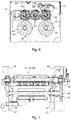
- the illustrated and advantageous embodiment are two screen printing units 11; 12 are provided, which are preferably combined in the same printing unit 04 and each between a forme cylinder 14; 16, e.g. B.
- a screen printing cylinder 14; 16, and a common impression cylinder 17 form two printing points for the same, here the first, side of the printing material 02 (see e.g. Fig. 4 ).
- a drying and / or curing device 18, e.g. B. a UV dryer 18 may be provided in the transport path between the two printing points. It can be with only one or both of the screen printing units 11; 12 optically variable coating agent 06 can be applied or can be applied.
- Impression and forme cylinder 17; 14; 16 are also used as a printing unit cylinder 14; 16; 17 designated.
- the printing material 02 can be fed to a first conveyor device 19 of the aligning device 07 via conveying devices.
- this can be one or more positively driven or non-driven rollers, via which the printing material 02 can be or is guided into the alignment device 07 on the input side.
- sheet-like printing material 02 i. H. individual printing material sheets 02 passing through the machine 01 are provided as conveying means, sheet-conveying means.
- this sheet-conveying means can be formed by one or more transfer cylinders or drums, which transfer the sheet of printing material 02 from the printing unit 04, e.g. B. from the impression cylinder 17, take over and, if necessary, deliver it to the alignment device 07 on the input side via a conveying device with one or more transfer cylinders or drums.
- the first conveyor device 19 is, however, as a gripper circulating conveyor 19, e.g. B. designed as a so-called.
- Chain gripper system 19 which on both sides of the frame endless traction means 21, z. B. includes endless chains 21, which carry gripper strips 22 running transversely to the transport direction. Leading sheet ends can be gripped by the gripper bars 22, the printing substrate sheets 02 can thus be transported along the conveying path and transferred to the corresponding conveying or receiving means at the destination.
- the printing substrate 02 is conveyed to a further, e.g. B. second conveyor 26 of a product receptacle 27 for receiving the processed and / or processed in the machine 01 printing material 02, z. B. a winder 27 in the case of web-shaped printing material 02 or a stack delivery 27 in the preferred case of sheet-shaped printing material 02, can be guided.
- this can again be one or more positively driven or non-driven rollers which continue the transport path of the first conveyor 19 and through the alignment device 07 and via which the printing material 02 can or will be guided on the input side into the winder 27.
- sheet-conveying means are provided as conveying means. As above, these can be formed by one or more transfer cylinders or drums which take over the printing material sheet 02 from the alignment device 07 and deliver it downstream to the stack delivery 27.
- the second conveyor device 26 is preferably, like the first, as a gripper circulating conveyor 26, e.g. B. chain gripper system 26 with revolving endless traction means 28, for. B. endless chains 28, one or more sprockets 31; 32 or chain gripper wheels 31; 32 and gripper bars 29 are formed, through which the printing material sheet 02 is taken over from the transport path section of the alignment device 07 and z. B. be fed to the stack delivery 27 (see e.g. Fig.
- a cooling device 33 is provided on the transport path between alignment device 07 and stack delivery 27, in particular behind the additional drying device in the transport path between alignment device 07 and exception device 27 (see e.g. Fig. 1 , Variant b)).
- This can be designed, for example, as a cooling roller 33, which is between the coming from the alignment device 07 second conveyor 26 and a third, z. B. also as a gripper conveyor 36, z. B. chain gripper system 36 executed conveyor 36 is arranged.
- an inspection device not shown, such. B. a surface or line camera, provided and directed, for example, to a lateral surface segment of the cooling roller 33 lying in the transport path.
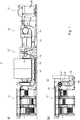
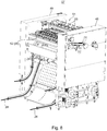
- Alignment device 07 is basically arbitrary in its designs, design variants or configurations, but is preferably provided or can be provided in a machine 01 or printing machine 01 described above. In an advantageous embodiment, it is designed in the form of a module and can be inserted into the transport path of the machine 01 to be equipped with input and output interfaces to the open section ends of a conveyor system continuing upstream and downstream.
- a type of module is to be understood here, for example, as a structural unit which, at least as a frame unit, consists of the two side parts 48; 49 can be inserted and removed.
- the device 07 for aligning optically variable picture elements 03, z. B. to align the optically variable effect in the previously - z. B. in the form of printing elements 08 - on the substrate 02, in particular printing material 02, applied optically variable coating agent 06 comprises a defined transport path, along which the substrate 02 to be conveyed by the alignment device 07 from a Entrance area, in which the substrate 02 to be treated and having optically variable coating agent 06 on its first side is fed or can be fed, in a defined manner to the active components 37; 38; 39; 37 *; 38 *; 39 *; 51; 52 is passed or promoted in an exit area.
- the first side having the optically variable coating agent 06 is to be understood as the side on which, for example, upstream in the transport path through the application device 04, the optically variable coating agent 06 is or is or has been applied.
- a second cylinder 38; 38 * is a group of cylinders 37; 38; 39; 37 *; 38 *; 39 * with at least one first cylinder 37; 37 * and downstream of this a second cylinder 38; 38 * are provided, which are arranged on different sides of a substrate 02 to be conveyed along the transport path.
- a third cylinder 39; 39 * is provided, which is on the same side of the transport path as the first cylinder 37; 37 * is arranged.
- Frame unit also already preassembled one, several or all of the group of cylinders 37; 38; 39; 37 *; 38 *; 39 * include.
- the first cylinder 37 has a plurality of elements 41 causing a magnetic field in the area of its outer circumference, hereinafter also referred to for short as magnetic elements 41, which allow for the orientation of at least part of the magnetic or magnetizable particles of the passing on the Coating agent 06 applied to the printing substrate are used.
- magnetic elements 41 which allow for the orientation of at least part of the magnetic or magnetizable particles of the passing on the Coating agent 06 applied to the printing substrate are used.
- several rows of magnetic elements 41 spaced from one another transversely to the transport direction are provided in the circumference, which in development on the substrate 02 with the pattern of the image elements 03 to which magnetic fields are to be applied on the substrate 02 correspond.
- the cylinder 37 comprising the magnetic elements 41 is also referred to below as the magnetic cylinder 37.
- the second cylinder 38 is only designed as a transport cylinder 38, ie without magnetic elements in the area of its outer circumference.
- the first cylinder 37 is assigned to the alignment device 07, and in particular not assigned to the application device 04 or is not also effective as a printing unit cylinder to form a printing point.
- the alignment device 07 includes a third cylinder 39 downstream of the second cylinder 38, in the basic version or configuration the third cylinder 39 * is also only designed as a transport cylinder 39 *, i.e. without magnetic elements in the area of its outer circumference ( see e.g. Fig. 12 b) .
- the third cylinder 39 of the alignment device 07 is also designed as a magnetic cylinder 39 and has a plurality of elements 42 causing a magnetic field in the area of its outer circumference in the manner set out above for the first magnetic cylinder 37, briefly below also referred to as magnetic elements 42, for orienting at least some of the magnetic or magnetizable particles of the coating agent 06 applied to the printing substrate 02 passing through.
- the magnetic members 42 may be arranged on the periphery of the second magnetic cylinder 39 in the same pattern as those of the first magnetic cylinder 37.
- first and second magnetic elements 41; 42 can also be designed and / or oriented differently, so that in the respective plane to be treated substrate 02 they cause a field line course that differs from one another in the direction and / or pattern.
- a magnetic cylinder 37; 38 *; 39 executed cylinder 37; 38 *; 39 can be designed without any holding means acting on the substrate 02 in the case of a web-shaped substrate 02. If necessary, suction air openings can be provided on the circumference, which are connected to a vacuum pump and ensure that the substrate 02 rests securely on the outer surface.
- arcuate substrate 02 are on the circumference of the cylinder 37; 38 *; 39 preferably holding means 43, e.g. B. gripper 43 of a so-called.
- Gripper bar provided through which a cylinder 37; 38 *; 39 substrate sheet 02 to be conveyed is received with its leading end and while the cylinder 37; 38 *; 39 can be held over an angular range.
- suction air openings in line with a vacuum pump can be provided on the circumference.
- a magnetic cylinder 37; 38 *; 39 also serves to transport the substrate 02, it is used in the context of the equipment with the above-mentioned magnetic elements 41; 42 is not considered here as a transport cylinder or designated.
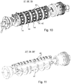
- the magnetic elements 41; 42 can be in or on several, z. B. between four and seven, in particular between four and six, axially spaced and preferably axially positionable ring elements 44 arranged or be able to be arranged, in or on these ring elements 44 in turn at least one, preferably several, z. B.
- magnetic elements 41; 42 are arranged or can be arranged one behind the other in the circumferential direction and preferably so that they can be positioned in the circumferential direction (see e.g. Fig. 10 ).
- magnetic field causing elements 41; 42 or magnetic elements 41; 42 are to be understood here as all magnetically active elements that permanently or switchably cause a magnetic field at least to the side of the transport path (in particular for aligning particles contained in the coating agent 06 on the substrate 02 passed over it as described here).
- the magnetic elements 41; 42 can be formed by permanent magnets with or without engraving, by electromagnets or by combinations of several permanent magnets and / or electromagnets. They can be operationally stationary or moved or movable on the operational cylinder 37; 38 *; 39 be arranged.
- a than - here in particular pure - transport cylinder 37 *; 38; 39 * executed cylinder 37 *; 38; 39 * has for the case of web-shaped substrate 02 z. B. on a cylindrical outer surface which is or is at least partially turned over by the web-shaped substrate 02 to be guided on the transport path.
- arcuate substrate 02 are on the circumference of the transport cylinder 37 *; 38; 39 * preferably holding means 46, e.g. B. gripper 46 of a so-called.
- Gripper bar provided through which a cylinder 37 *; 38; 39 * substrate sheet 02 to be conveyed is received with its leading end and while the transport cylinder 37 *; 38; 39 * is or can be held over an angular range.
- a transport cylinder 37 *; 38; 39 * designated cylinder 37 *; 38; 39 * does not have to have a predominantly closed outer cylinder surface, but can only in extreme cases comprise at least one gripper bar, spaced around the cylinder axis, on a cylindrical enveloping surface.
- further axially extending webs and / or axially spaced support disks or rings 47 can be provided (see e.g. Fig. 11 ).
- the cylindrical envelope surface lying in the transport path is predominantly open in its effective angular segment, ie to more than 50% inward, while it is on the magnetic cylinder 37; 38 *; 39 is predominantly, ie more than 50% closed.
- the angle segment coming to lie under the substrate 02 or substrate section during its transport is on the relevant cylinder 37; 38; 39; 37 *; 38 *; 39 *.
- the two or preferably three cylinders 37; 38; 39; 37 *; 38 *; 39 * are each rotatable at the front in frame walls 48; 49, e.g. B. side panels 48; 49 of a frame carrying the components of the alignment device 07.
- the pins of the cylinder 37 to be arranged in the first place; 37 * receiving bearing means designed in such a way that the first cylinder position of the group of cylinders 37; 38; 39; 37 *; 38 *; 39 * can optionally be equipped with a magnetic cylinder 37 or a transport cylinder 37 * (see e.g. Fig. 12 ).
- pins and bearing structure for the two different types of cylinders 37; 38; 39; 37 *; 38 *; 39 * designed identically in the at least two, preferably three cylinder positions of the cylinder group comprised by the alignment device 07.
- the three cylinders 37; 38; 39; 37 *; 38 *; 39 * or their bearings are preferably provided in the frame in such a way that the three cylinder axes essentially lie in a common plane, for example a horizontal plane. No or at most a maximum distance between the axis of the central cylinder 38; 38 * from the connecting plane through the axes of the two outer cylinders 37; 39; 37 *; 39 * at most 30 mm, preferably at most 10 mm.
- At least one first drying and / or curing device 51 is preferably arranged or can be arranged on the transport path of the substrate 02 to be conveyed through the alignment device 07, in particular printing material 02, on its first side having the optically variable coating agent 06.
- This is viewed in the transport direction T on a lateral surface segment lying in the transport path of the z. B. designed as a magnetic cylinder 37 first cylinder 37 or directed to a point in the transport path at which the substrate 02 to be conveyed in operation - in particular with its second side - on the, z. B. as Magnetic cylinder 37 executed first cylinder 37; 37 * is performed.
- the drying and / or curing device 51 is preferably designed as a radiation dryer and operates on the basis of electromagnetic radiation, e.g. B. with IR or preferably UV radiation. For this purpose, it has one or more radiation sources, e.g. B. IR or preferably UV light sources.
- First drying and / or curing device 51 it is designed - in at least one operating mode - not to act continuously on the substrate 02 to be treated over its entire width, but in sections spaced apart from one another. These are preferably adjustable in their position transversely to the transport direction of the substrate 02 and, if necessary, can be defined in their respective effective width.
- the drying and / or curing device 51 can transverse to the transport direction T side by side several, z. B. between four and seven, in particular between four and six, directed to the transport path dryer and / or curing elements 53, z. B. dryer heads 53, which are preferably variable in their position transversely to the transport direction T.
- the dryer heads 53 are preferably designed as radiation dryer heads 53 and can each have one or more radiation sources, e.g. B. IR or preferably UV radiation sources include.
- include Dryer heads 53 each have a plurality (e.g. more than 10) of LEDs, e.g. B.
- IR-LEDs or preferably UV-LEDs, formed radiation sources which are arranged at the head end of the respective dryer head 53, for example in the manner of a one or preferably two-dimensional array.
- the dryer heads 53 are arranged, for example, on a crossbeam and can preferably be moved transversely on this and thus their position can be adjusted.
- the drying and / or curing device 51 comprising the traverse and dryer heads 53 is in an advantageous development as a structural unit, e.g. B. module, executed and as such in or on the side parts 48; 49 of the frame can be used and removed from these.
- the side parts 48; 49 of the frame have z. B. for this purpose appropriately prepared connection elements or points.
- the first drying and / or curing device 51 can be omitted or removed during conversion.
- At least one masking element (not shown here) and a fastening mechanism are provided through which the masking element enters the radiation path between the dryer - and / or curing element 53 and transport path is to be positioned in such a way that a defined delimitation of the irradiated area in the plane of the transport path with respect to the irradiated area is effected during operation without masking.
- masking elements of different sizes can be provided and / or the masking element can be moved with at least one component transversely to the beam direction relative to the dryer and / or curing element 53.
- the drying and / or curing device 51 can be a dryer and / or curing element 54, e.g. B. in the manner of a light strip 54, in particular LED light strip, which or which transversely to the transport direction T a plurality, in particular a plurality of z. B. more than 100 directly next to each other, ie at least less than 5 mm, in particular at least less than 2 mm spaced apart in the transverse direction, arranged radiation sources, z. B.
- IR or preferably UV radiation sources includes. These can preferably be as LEDs, e.g. B.
- the light sources can be arranged in or on a one-part or multi-part frame part, for which z. B. - contrary to the dryer and / or curing elements 53 from the first embodiment variant - no axial mobility is provided for setting the intended jet position.
- the above-mentioned sections, on which the action on the substrate 02 is to take place, are or are formed by groups of active or to be activated radiation sources, between which groups of inactive or not to be activated light sources are located.
- the sections can be varied in their position and preferably width by defining the active or to be activated radiation sources.
- Groups of radiation sources can already be firmly defined and can only be selected as belonging to the active or inactive groups.
- the sections can be defined in terms of position and width by forming groups of radiation sources to be activated or sub-groups of radiation groups.
- mask elements can also be provided which, comparable to the first variant, are to be positioned in the radiation path between the dryer and / or curing element 54 and the transport path in such a way that the irradiated Area in the plane of the transport path compared to the irradiated area during operation without masking can be limited even more by, for example remaining diffuse beam components are retained.
- mask elements of different sizes and / or a relatively movable arrangement can be provided.
- the drying and / or curing device 51 in the second variant is also designed in an advantageous further development as a structural unit or module and as such as a whole in or on the frame walls or side parts 48; 49 of the frame can be inserted and removed therefrom, the side parts 48; 49 of the frame z. B. have accordingly prepared connection elements or points for this purpose.
- the first cylinder 37 * is configured as a transport cylinder 37 *
- the first drying and / or curing device 51 can be omitted or removed during conversion.
- a second drying is a further effective component 52 on the transport path of the substrate 02 to be conveyed by the aligning device 07, in particular printing material 02 - And / or curing device 52 is provided.
- it can in principle also be provided downstream thereof, viewed in the transport direction T it is preferably applied to a lateral surface segment of the z. B. designed as a magnetic cylinder 39 third cylinder 39 or directed to a point in the transport path at which the substrate 02 to be conveyed in operation on this further magnetic cylinder 38 *; 39 is performed.
- the point viewed in the transport direction T at which the second drying and / or curing device 52 is directed is preferably again at least 90 ° behind the point at which the substrate 02 to be conveyed on its transport path on this further magnetic cylinder 38 *; 39 runs up and in front of the point at which the on its transport path over this cylinder 38 *; 39 to be conveyed substrate 02 the cylinder 38 *; 39 leaves again. It can be an advantage if the circumferential length between the running of the substrate 02 onto the further magnetic cylinder 38 *; 39 and the point of action of the second drying and / or curing device 52 corresponds approximately, ie up to ⁇ 10% of the possibly larger value, to the corresponding circumferential length on the first magnetic cylinder 37.
- the second drying and / or curing device 52 is preferably designed as a radiation dryer and operates on the basis of electromagnetic radiation, e.g. B. with IR or preferably UV radiation.
- electromagnetic radiation e.g. B. with IR or preferably UV radiation.
- it has one or more radiation sources, e.g. B. IR or preferably UV light sources.
- the second drying and / or curing device 52 can basically be designed in accordance with the first embodiment variant for the first drying and / or curing device 51 in order, for example, to cure or cure only not yet dried or cured areas of printing elements 08 applied singularly to the substrate 02. to dry. The above is to be applied accordingly.
- the required width, z. B. at least the width of the maximum substrate width to be treated in the device 07, continuously extending dryer and / or curing element 56, z. B. in the manner of a light strip 56, in particular LED light strip, which or which transversely to the transport direction a plurality, in particular a plurality of z. B. more than 100 directly next to each other, ie less than 10 mm apart, arranged radiation sources, z. B. IR or preferably UV radiation sources includes.
- the radiation sources can preferably be LEDs, z. B.
- the dryer and / or curing element 56 embodied in this way can, but does not have to, with regard to a section-wise action corresponding to the above-mentioned second embodiment variant for the first dryer and / or curing element 54 can be designed to be switchable.
- the second drying and / or curing device 52 comprising the dryer and / or curing element 56 is designed in an advantageous further development as a structural unit or module and as such as a whole in or on the side parts 48; 49 of the frame can be inserted and removed therefrom, the side parts 48; 49 of the frame z. B. have accordingly prepared connection elements or connection points for this purpose.
- the third cylinder 39 * is configured as a transport cylinder 39 *
- the second drying and / or curing device 52 can be omitted or removed during conversion.
- the second cylinder 38 * is designed or configured as a magnetic cylinder 38 * instead of the third cylinder 39 *
- the second drying and / or curing device 52 can be used at appropriately prepared termination points on the second cylinder 38 *.
- the alignment device 07 or the machine 01 comprising it is designed for handling and treating sheet-shaped substrates 02, in particular substrate sheets 02
- the alignment device 07 comprises, in addition to the at least two, in particular three, cylinders 37; 38; 39; 37 *; 38 *; 39 * on the input side a transfer point at which a substrate sheet 02 to be treated is transferred from the upstream conveyor 19 to the first cylinder 37; 37 * is or can be transferred to the alignment device 07, and on the output side a transfer point at which a treated substrate sheet 02 from the last cylinder 38; 39; 38 *; 39 * of the cylinder group comprised by the alignment device 07 is or can be transferred to a downstream conveyor device 26.
- the respective transfer point can, in principle, for the case of upstream or downstream transport cylinders, by the interaction of a last or first transport cylinder with the first or last cylinder 37; 38; 39; 37 *; 38 *; 39 * of the alignment device 07 may be formed.
- a gripper circulating conveyor 19; 26 trained conveyors 19; 26 the transfer on the input side takes place between a gripper bar 22 of the upstream gripper conveyor 19 and the first cylinder 37; 37 * and the transfer on the output side between the last cylinder 38; 39; 38 *; 39 * of the cylinder group and a gripper bar 29 of the gripper rotary conveyor 26 following downstream.
- the transfer or takeover by the gripper bars 22; 29 are preferably carried out in the area of the chain gripper wheel 24; 31 caused a turn, in particular at the level of the intersection of the transport path with the axis of the chain gripper wheel 24; 31 with the axis of the relevant cylinder 37; 38, 39; 37 *; 38 *; 39 * connecting level.
- the three-cylinder design of the alignment device 07 in the configuration for handling arcuate substrate 02 preferably comprises three cylinders 37; 38; 39; 37 *; 38; 39 *, in the front side parts 48; 49 are stored, as well as on at least one of the side parts 48; 49 two chain gripper wheels 24; 31; 24 '; 31 '.
- the side parts 48; 49 together with these connecting cross members and / or floor plates, the cylinders 37; 38; 39; 37 *; 38; 39 *, and in an advantageous development the chain gripper wheels 24; 31; 24 '; 31 ' is designed as a module in the form of a structural unit and as such can be inserted into or removed from the machine 01 in one piece.
- the cylinders 37; 38; 39; 37 *; 38; 39 * of the cylinder group can in principle be replaced by one or more, only these cylinders 37; 38; 39; 37 *; 38; 39 * assigned drive motors, e.g. B. be driven jointly by one or individually by several position-controlled servomotors.
- the first cylinder 37; 37 * and from there successively to the remaining cylinders 38; 39; 38 *; 39 * driven.
- This gear 57 meshes directly or via an even number of intermediate gears with a gear 59 which is connected to the axis of the cylinder 37 to be driven; 38; 39; 37 *; 38 *; 39 *, e.g. B. the first cylinder 37; 37 *, is non-rotatably connected.
- This gear 59 or a further gear which is also non-rotatably arranged on the axis meshes with a gear 61 which is connected to the axis of the adjacent cylinder 37; 38; 39; 37 *; 38 *; 39 *, e.g. B.
- the second cylinder 38; 38 * of the cylinder group is non-rotatably connected.
- the last-mentioned gear 61 or a further gear which is non-rotatably arranged on the same axis and has a gear 62 which rotates with the axis of the remaining cylinder 37; 38; 39; 37 *; 38 *; 39 *, e.g. B.
- the third cylinder 39, 39 * is connected. If the alignment device 07 continues to the other, z. B. downstream conveyor system 26 are driven further, so meshes the last-mentioned gear 62 or a non-rotatably arranged on the same axis further gear directly or via an even number of intermediate gears with a gear 63, which is rotatably connected to a shaft 64, which rotatably at least one of the chain gripper wheels 31; 31 'wears.
- the substrate 02 is preferably transferred directly between cylinders 37; 38; 39; 37 *; 38 *; 39 * the Cylinder group.
- a guide device with blow openings facing the transport path can be provided.
- a guide device 73 e.g. B. an air box with the transport path facing blowing air openings may be provided, which support the substrate sheet 02 during the turn.
- the second cylinder 38 * can be designed as a magnetic cylinder 38 * with an above-described pattern of magnet elements 41, 42 arranged on the circumference, or can be configured in this way by retrofitting the basic configuration.
- the configuration of the two-cylinder group for example for operation without aligning a variable picture element - both cylinders 37 *; 38 with transport cylinders 37 *; 38 can be configured.
- a cylinder group with three cylinders 37; 38; 39; 37 *; 38 *; 39 * can deviate from or as an alternative to the above-mentioned particularly advantageous design or configuration (see e.g. Fig. 12 c) )
- Different designs or configurations can be implemented and are advantageous: If only a single-stage orientation of the particles contained in the coating agent 06 is provided or required, then in the alignment device 07, as in the basic version, at only one of the cylinder positions for the cylinders 37; 38; 39; 37 *; 38 *; 39 *, e.g. B. that of the first cylinder 37, a magnetic cylinder 37 and at the other cylinder positions only as a transport cylinder 38; 39 * trained cylinder 38; 39 * must be provided (see e.g. Fig. 12 b) ),
- a configuration can be advantageous, with only one in all three cylinder positions as transport cylinder 37 *, 38; 39 * formed cylinder 37 *, 38; 39 * is or will be provided (see e.g. Fig. 12 a) ).
- a two-stage alignment can be carried out, with the alignment taking place from the same side of the transport path.
- all three cylinder positions can be used as magnetic cylinders 37; 38 *; 39 formed cylinder 37; 38 *; 39 (see e.g. Fig. 12 e) ).
- the second cylinder 38 * is designed or configured as a magnetic cylinder 38 *, it is advantageous if the magnetic elements encompassed by this on the circumference are arranged with their surfaces facing the transport path offset radially inward relative to the surfaces supporting the substrate 02 on a cylindrical envelope surface are, d. H. not flush with the support surface. This prevents any smearing of coating agent 06 that may have not yet dried due to physical contact with the magnetic elements.
- cylinder 37; 38 *; 39 formed cylinder 37; 38 *; 39 can be a smoothing device, e.g. B. a plurality of axially spaced rollers or one or more rollers can be provided, which in the transport path of the substrate 02 between the point of emergence and the point of drying or hardening over the substrate 02 to the cylinder 37; 38 *; 39 is employed or employable.
- a smoothing device e.g. B. a plurality of axially spaced rollers or one or more rollers can be provided, which in the transport path of the substrate 02 between the point of emergence and the point of drying or hardening over the substrate 02 to the cylinder 37; 38 *; 39 is employed or employable.
- the magnetic cylinder 37; 38 *; 39 formed cylinder 37; 38 *; 39 can this one, in particular contactless transmitter, z.
- Coupler for the transmission of electrical energy and / or control signals from the outside in the rotating cylinder 37; 38 *; 39 include.
- each is designed as a magnetic cylinder 37; 38 *; 39 formed cylinder 37; 38 *; 39 a dedicated vacuum pump is provided for supplying suction air openings provided on its outer surface.
- a magnetic cylinder 37; 38 *; 39 formed cylinder 37; 38 *; 39 can such as Am Fig. 10 shown without a cover between the magnetic elements 41; 42 load-bearing Ring elements 44 may be formed and optionally have additional support rings between the ring elements 44, or a cover, e.g. B. have a cover plate in which areas for the magnetic elements 41; 42 are omitted and which z. B. has holes as suction air openings.
- the magnetic cylinder 41 which is advantageous in terms of format variability and / or variability in the position of the variable picture elements 03 on the substrate 03 or panel 09; 42 (see e.g. Fig. 13 ) are at least two adjacent, but preferably all of the magnetic elements 41; 42 containing or equippable with these axially movable ring elements 44 at least in one to the cylindrical envelope surface of the cylinder 39; 38 *; 39 contributing cover element 71 on the in the axial direction of the cylinder 37; 38 *; 39 sides facing each other in the axial direction in such a tooth-like or fan-like manner with projections 66, for. B. in the form of tabs 66 or lugs 66, and corresponding recesses 67, z. B.
- the ring elements 44 can be designed in one or more parts. You can total, so in the area of their side walls 68; 69 as well as in the area of the outwardly facing cover elements 71 in this tooth-like manner or, in an advantageous embodiment, circular disk-shaped side walls 68; 69 and a cover element 71 having the recesses 67 and projections 66, e.g. B. at their edges in the manner mentioned toothed cover plates or strips 71 have.
- the cover element 71 can have the outwardly facing wall in one piece executed ring element 44 or a component specially arranged on the ring element 44, e.g. B. be cover plate or strips.
- edges of the recesses 67 and projections 66 continue in an undulating manner and are thus formed without sharp corners.
- the cover element 71 has recesses for the magnetic elements 41; 42 on.
- a plurality of suction air openings 72 are preferably provided in the respective cover element 71 and are located in a space below between the side walls 68; 69 and the cover element 71 by a line connection to a vacuum pump, a negative pressure can be generated.
Landscapes
- Engineering & Computer Science (AREA)
- Mechanical Engineering (AREA)
- Toxicology (AREA)
- Health & Medical Sciences (AREA)
- General Health & Medical Sciences (AREA)
- Physics & Mathematics (AREA)
- Electromagnetism (AREA)
- Thermal Sciences (AREA)
- Supply, Installation And Extraction Of Printed Sheets Or Plates (AREA)
- Coating Apparatus (AREA)
- Rotary Presses (AREA)
- Screen Printers (AREA)
- Application Of Or Painting With Fluid Materials (AREA)
- Ink Jet (AREA)
Claims (15)
- Dispositif destiné à orienter des particules magnétiques ou magnétisables qui sont contenues dans un agent de revêtement (06) déposé sur un premier côté d'un substrat (02) en forme de bande ou d'arc,
qui comprend- un équipement d'application (04) agencé dans le chemin de transport du substrat (02), par lequel l'agent de revêtement (06) est et/ou peut être déposé contre au moins un emplacement d'application sur le premier côté du substrat (02),- un premier cylindre (37) exécuté en tant que cylindre magnétique (37) qui est agencé dans le chemin de transport du substrat (02) à acheminer en aval de l'équipement d'application (04) et présente dans la zone de sa périphérie extérieure une pluralité d'éléments (41) qui provoquent un champ magnétique,- un autre cylindre (38* ; 39) exécuté en tant que cylindre magnétique (38* ; 39), qui est agencé dans le chemin de transport du substrat (02) à acheminer en aval du premier cylindre (37) exécuté en tant que cylindre magnétique (37) et présente dans la zone de sa périphérie extérieure une pluralité d'éléments (42) qui provoquent un champ magnétique,- un équipement de séchage et/ou durcissement (51) qui est agencé contre le chemin de transport entre l'emplacement de l'accumulation du substrat (02) sur le premier cylindre (37) et l'emplacement de l'accumulation sur l'autre cylindre (38* ; 39),caractérisé en ce que
le premier cylindre (37) exécuté en tant que cylindre magnétique (37) est agencé dans le chemin de transport du substrat (02) à acheminer sur le second côté de celui-ci, et l'équipement de séchage et/ou durcissement (51) est orienté dans le chemin de transport du substrat (02) à acheminer sur le premier côté de celui-ci. - Dispositif selon la revendication 1, caractérisé en ce que l'autre cylindre (39) est prévu en tant que troisième cylindre (39) en aval d'un deuxième cylindre (38 ; 38*) agencé après le premier cylindre (37) et est agencé dans le chemin de transport du substrat (02) à acheminer sur le même côté du chemin de transport que le premier cylindre (37).
- Dispositif selon la revendication 2, caractérisé en ce que le deuxième cylindre (38) est exécuté en tant que cylindre de transport (38) par lequel le substrat (02) peut être et/ou est amené depuis le premier cylindre (37) jusqu'au troisième cylindre (39).
- Dispositif selon la revendication 2, caractérisé en ce que le deuxième cylindre (38*) est également exécuté en tant que cylindre magnétique (38*) et présente dans la zone de sa périphérie extérieure une pluralité d'éléments qui provoquent un champ magnétique.
- Dispositif selon la revendication 1, caractérisé en ce que le deuxième cylindre (38* ; 39) en tant que deuxième cylindre (38*) suit directement le premier cylindre (37) dans le chemin de transport du substrat (02) à acheminer et est agencé en tant que premier cylindre (37) sur l'autre côté du chemin de transport.
- Dispositif selon la revendication 5, caractérisé en ce qu'après le deuxième cylindre (38*) est agencé un troisième cylindre (39 ; 39*) qui suit directement le deuxième cylindre (38*) dans le chemin de transport du substrat (02) à acheminer.
- Dispositif selon la revendication 2, 3, 4 ou 6, caractérisé en ce que le deuxième cylindre (38 ; 38*) est agencé en tant que premier cylindre (37) sur l'autre côté du chemin de transport.
- Dispositif selon la revendication 2, 3, 4, 6 ou 7, caractérisé en ce que le premier cylindre (37) prévu dans le chemin de transport en une première position de cylindre, le deuxième cylindre (38 ; 38*) prévu en une deuxième position de cylindre et le troisième cylindre (39 ; 39*) qui suit le deuxième cylindre (38 ; 38*) en une troisième position de cylindre sont ou peuvent être montés en rotation dans des parois de bâti (48 ; 49) d'un bâti.
- Dispositif selon la revendication 8, caractérisé en ce que les moyens de stockage qui accueillent les tenons du cylindre (38 ; 38*) à agencer en une deuxième position sont conçus de telle sorte que la deuxième position de cylindre peut être, au choix, équipée et/ou configurée avec un cylindre (39) réalisé en tant que cylindre magnétique (38*) correspondant au premier cylindre (37) avec une pluralité d'éléments (42) qui provoquent un champ magnétique ou avec un cylindre (38) réalisé en tant que cylindre de transport (38), et/ou en ce que les moyens de stockage qui accueillent les tenons du cylindre (39 ; 39*) à agencer en une troisième position sont conçus de telle sorte que la troisième position de cylindre puisse être, au choix, équipée et/ou configurée avec un cylindre (39) réalisé en tant que cylindre magnétique (39) correspondant au premier cylindre (37) avec une pluralité d'éléments (42) qui provoquent un champ magnétique ou avec un cylindre (38) réalisé en tant que cylindre de transport (39*).
- Dispositif selon la revendication 9, caractérisé en ce que les moyens de stockage qui accueillent les tenons du cylindre (37 ; 37*) à agencer en une première position sont conçus de telle sorte que la première position de cylindre peut être, au choix, équipée et/ou configurée, à la place du cylindre magnétique (37), avec un cylindre de transport (37*) correspondant au deuxième cylindre (38).
- Dispositif selon la revendication 1, 2, 3, 4, 5, 6, 7, 8 ou 9, caractérisé en ce que le premier équipement de séchage et/ou durcissement (51) comprend une pluralité de sources de rayonnement qui sont prévues dans plusieurs têtes de séchage (53) qui définissent les sections ou dans un réseau de sources de rayonnement qui passe par l'épaisseur de substrat maximale à traiter et peut cependant être activé, et/ou en ce que le premier équipement de séchage et/ou durcissement (51) comprend une pluralité de sources de rayonnement réalisées en tant que DEL UV et/ou est réalisé de façon à agir sur le substrat (02) à traiter dans des sections espacées les unes des autres transversalement à la direction de transport (T) et/ou est orienté vers un segment de surface d'enveloppe, du premier cylindre (37), qui se situe dans le chemin de transport, dans le chemin de transport du substrat (02) à acheminer, et/ou est agencé de façon à être orienté vers un emplacement du chemin de transport qui se situe contre la périphérie du premier cylindre (37).
- Dispositif selon la revendication 11, caractérisé en ce que les sections peuvent être réglées dans leur position transversalement à la direction de transport (T) et/ou en ce que l'équipement de séchage et/ou durcissement (51) comprend une pluralité de sources de rayonnement qui sont prévues dans plusieurs têtes de séchage (53) qui définissent les sections ou dans un réseau de sources de rayonnement qui passe par l'épaisseur de substrat maximale à traiter et peut cependant être partiellement activé.
- Machine (01) destinée à produire des éléments d'image (03) optiquement variables sur un substrat (02), qui comprend une présentation de substrat (13), en particulier exécutée en tant que margeur de feuille (13), au moins une unité d'impression (04) avec au moins un groupe d'impression (11 ; 12), en particulier un groupe de sérigraphie (11 ; 12), par lequel un substrat (02) amené par la machine (01) sur un chemin de transport est et/ou peut être imprimé au moins sur un premier côté, une réception de produit (27), en particulier exécutée en tant que sortie d'empilage (27), ainsi qu'un dispositif (07) prévu dans le chemin de transport du substrat (02) entre l'unité d'impression (04) et la réception de produit (27) pour l'orientation de particules magnétiques ou magnétisables selon l'une des revendications 1 à 12.
- Procédé destiné à appliquer et orienter des particules magnétiques ou magnétisables contenues dans un agent de revêtement (06), dans lequel- l'agent de revêtement (06) qui contient les particules magnétiques ou magnétisables est appliqué dans un équipement d'application (04) formé par une unité d'impression (04) sur un premier côté d'un substrat (02) en forme de bande ou d'arc,- en aval de l'équipement d'application (04), le substrat (02) est amené tout d'abord par un premier cylindre (37) qui présente des éléments magnétiques (41) dans la zone de sa périphérie extérieure, pour l'orientation d'au moins une partie des particules,- et au plus tôt après l'accumulation du substrat (02) sur le premier cylindre (37), un équipement de séchage et/ou durcissement (51) passe,- dans lequel, après avoir quitté le premier cylindre (37) et en aval du premier équipement de séchage et/ou durcissement (51), le substrat (02) est amené par un autre cylindre (38* ; 39) qui présente des éléments magnétiques (42) dans la zone de sa périphérie extérieure, pour l'orientation d'au moins une partie des particules,caractérisé en ce que le substrat (02) est amené par le premier cylindre (37) avec son premier côté présentant l'agent de revêtement (06) tourné vers l'extérieur,
et en ce que l'équipement de séchage et/ou durcissement (51) est orienté vers le premier côté du substrat (02). - Procédé selon la revendication 14, caractérisé par les étapes suivantes réalisées en ligne dans une machine :- application de l'agent de revêtement (06) sur le substrat (02) ;- amenée du substrat (02) par un premier cylindre (37) qui présente des éléments magnétiques (41) dans la zone de sa périphérie extérieure,- séchage partiel de l'agent de revêtement (06) encore pendant le contact du substrat (02) avec le premier cylindre (37) ou à la suite,- amenée du substrat (02) par un autre cylindre (38* ; 39) qui présente des éléments magnétiques (42) dans la zone de sa périphérie extérieure,- et séchage sur toute la surface ou partiel de l'agent de revêtement (06) encore pendant le contact du substrat (02) avec l'autre cylindre (38* ; 39) ou à la suite.
Applications Claiming Priority (3)
| Application Number | Priority Date | Filing Date | Title |
|---|---|---|---|
| DE102018205882.2A DE102018205882B4 (de) | 2018-04-18 | 2018-04-18 | Vorrichtung und Maschine zum Ausrichten von magnetischen oder magnetisierbaren Partikeln auf einem bahn- oder bogenförmigen Substrat |
| DE102018205883.0A DE102018205883B4 (de) | 2018-04-18 | 2018-04-18 | Vorrichtung und Maschine zum Ausrichten von magnetischen oder magnetisierbaren Partikeln auf einem bahn- oder bogenförmigen Substrat |
| PCT/EP2019/050889 WO2019201481A1 (fr) | 2018-04-18 | 2019-01-15 | Dispositifs, machines et procédé d'application et d'orientation de particules magnétiques ou magnétisables sur un substrat en forme de bande ou de feuille |
Publications (2)
| Publication Number | Publication Date |
|---|---|
| EP3781403A1 EP3781403A1 (fr) | 2021-02-24 |
| EP3781403B1 true EP3781403B1 (fr) | 2021-11-24 |
Family
ID=65036785
Family Applications (1)
| Application Number | Title | Priority Date | Filing Date |
|---|---|---|---|
| EP19700895.6A Active EP3781403B1 (fr) | 2018-04-18 | 2019-01-15 | Dispositifs, machines et procédé d'application et d'orientation de particules magnétiques ou magnétisables sur un substrat en forme de bande ou de feuille |
Country Status (4)
| Country | Link |
|---|---|
| US (1) | US11155075B2 (fr) |
| EP (1) | EP3781403B1 (fr) |
| JP (1) | JP6991349B2 (fr) |
| WO (1) | WO2019201481A1 (fr) |
Families Citing this family (4)
| Publication number | Priority date | Publication date | Assignee | Title |
|---|---|---|---|---|
| CN113547834B (zh) * | 2021-07-14 | 2023-04-07 | 中钞印制技术研究院有限公司 | 多光彩光变印刷装置及其印刷方法 |
| MX2024011138A (es) * | 2022-04-13 | 2024-09-19 | Koenig & Bauer Ag | Cilindro para la alineacion de particulas magneticas o magnetizables contenidas en un agente de revestimiento en un sustrato y una maquina para la generacion de elementos de imagen opticamente variable. |
| EP4444548B1 (fr) * | 2022-04-13 | 2025-11-05 | Koenig & Bauer AG | Cylindre pour aligner des particules magnétiques ou magnétisables, système pour monter et/ou positionner des éléments magnétiques sur le cylindre, et machine pour générer des éléments d'image optiquement variables |
| CN114801436B (zh) * | 2022-04-22 | 2024-05-24 | 中钞印制技术研究院有限公司 | 多光彩光变印刷装置及其印刷方法、可读存储介质 |
Family Cites Families (13)
| Publication number | Priority date | Publication date | Assignee | Title |
|---|---|---|---|---|
| DE602004026193D1 (de) * | 2003-06-30 | 2010-05-06 | Kba Giori Sa | Druckmaschine |
| EP1961559A1 (fr) | 2007-02-20 | 2008-08-27 | Kba-Giori S.A. | Corps cylindrique d'orientation de paillettes magnétiques contenues dans une encre ou un vernis appliquées sur un substrat en forme de feuille ou de bande |
| TWI487626B (zh) * | 2008-12-10 | 2015-06-11 | Sicpa Holding Sa | 用於磁性取向及印刷的裝置及製程 |
| MY166194A (en) * | 2010-09-24 | 2018-06-07 | Sicpa Holding Sa | Device, system and method for producing a magnetically induced visual effect |
| ES2540864T3 (es) | 2010-09-24 | 2015-07-14 | Kba-Notasys Sa | Sistema y método para orientar escamas o laminillas magnéticas contenidas en un vehículo de tinta o barniz aplicado sobre un sustrato en forma de lámina o en forma de banda |
| EP2468423B1 (fr) * | 2010-12-27 | 2016-05-11 | Viavi Solutions Inc. | Système et procédé de formation d'une image sur un substrat |
| DE112012006348B4 (de) | 2012-05-09 | 2018-09-13 | China Banknote Printing And Minting Corp. | Kombinationsdruckvorrichtung |
| TW201605655A (zh) | 2014-07-29 | 2016-02-16 | 西克帕控股有限公司 | 用於由磁場產生裝置產生凹形磁力線所製成之光學效果層之場內硬化之方法 |
| JP6616823B2 (ja) | 2014-08-26 | 2019-12-04 | カーベーアー−ノタシ ソシエテ アノニム | 複合印刷機 |
| CA2959603A1 (fr) | 2014-09-12 | 2016-03-17 | Kba-Notasys Sa | Presse d'impression combinee |
| EP3015266A1 (fr) | 2014-10-30 | 2016-05-04 | KBA-NotaSys SA | Presse d'impression comprenant une unité d'orientation magnétique et une unité déplacable de séchage et de durcissement |
| CN105034570B (zh) | 2015-09-10 | 2017-10-17 | 惠州市华阳光学技术有限公司 | 一种磁性印刷品的制造设备 |
| EP3178569A1 (fr) | 2016-06-29 | 2017-06-14 | Sicpa Holding Sa | Procédés et dispositifs pour produire des couches à effet optique au moyen d'un photomasque |
-
2019
- 2019-01-15 EP EP19700895.6A patent/EP3781403B1/fr active Active
- 2019-01-15 WO PCT/EP2019/050889 patent/WO2019201481A1/fr not_active Ceased
- 2019-01-15 US US17/040,753 patent/US11155075B2/en active Active
- 2019-01-15 JP JP2020544916A patent/JP6991349B2/ja active Active
Also Published As
| Publication number | Publication date |
|---|---|
| US20210016560A1 (en) | 2021-01-21 |
| JP6991349B2 (ja) | 2022-01-12 |
| US11155075B2 (en) | 2021-10-26 |
| EP3781403A1 (fr) | 2021-02-24 |
| WO2019201481A1 (fr) | 2019-10-24 |
| JP2021509643A (ja) | 2021-04-01 |
Similar Documents
| Publication | Publication Date | Title |
|---|---|---|
| EP3877182B1 (fr) | Dispositif et machine d'impression pour produire un element de securite sur un substrat | |
| DE102018205885B4 (de) | Zylinder, Vorrichtung und Maschine zum Ausrichten von magnetischen oder magnetisierbaren Partikeln auf einem bahn- oder bogenförmigen Substrat | |
| DE102018205882B4 (de) | Vorrichtung und Maschine zum Ausrichten von magnetischen oder magnetisierbaren Partikeln auf einem bahn- oder bogenförmigen Substrat | |
| EP4178805B1 (fr) | Machine pour générer des éléments d'image optiquement variables | |
| DE102022109038B3 (de) | Vorrichtung zum Ausrichten von magnetischen oder magnetisierbaren Partikeln sowie Maschine zur Erzeugung optisch variabler Bildelemente | |
| WO2019201481A1 (fr) | Dispositifs, machines et procédé d'application et d'orientation de particules magnétiques ou magnétisables sur un substrat en forme de bande ou de feuille | |
| DE102021105635A1 (de) | Siebdruckeinheit mit Ausrichtzylinder | |
| EP4221982B1 (fr) | Unité d'impression de feuilles conçue en tant qu'unité de sérigraphie et procédé de fonctionnement d'une unité d'impression de feuilles en tant qu'unité de sérigraphie | |
| DE102019108765A1 (de) | Druckmaschine und Verfahren zur Herstellung von Druckprodukten | |
| DE102018205883A1 (de) | Vorrichtung und Maschine zum Ausrichten von magnetischen oder magnetisierbaren Partikeln auf einem bahn- oder bogenförmigen Substrat | |
| EP4221983B1 (fr) | Unité d'impression à feuilles se présentant sous la forme d'une unité de sérigraphie et comportant deux modules de base | |
| DE102022109036A1 (de) | Vorrichtung zum Ausrichten von magnetischen oder magnetisierbaren Partikeln sowie Maschine zur Erzeugung optisch variabler Bildelemente | |
| EP4496709B1 (fr) | Dispositif permettant d'aligner des particules magnétiques ou magnétisables, et machine permettant de générer des éléments d'image optiquement variables | |
| EP4182171B1 (fr) | Unité d'impression alimentée à feuilles sous forme d'unité d'impression sérigraphique | |
| DE102020125728B3 (de) | Vorrichtung zum Ausrichten von magnetischen oder magnetisierbaren Partikeln sowie Maschine zur Erzeugung optisch variabler Bildelemente | |
| DE102020125727B3 (de) | Vorrichtung zum Ausrichten von magnetischen oder magnetisierbaren Partikeln sowie Maschine zur Erzeugung optisch variabler Bildelemente | |
| EP4457096B1 (fr) | Unité d'impression dotée d'un dispositif d'alignement, position d'impression sans percussion et dispositif de durcissement | |
| EP4457095B1 (fr) | Unité d'impression ayant deux modules de base et une position d'impression sans impact | |
| DE102021105638A1 (de) | Siebdruckeinheit mit freiem Siebachsbereich | |
| WO2023247133A1 (fr) | Unité d'impression dotée d'un dispositif d'alignement, position d'impression sans percussion et dispositif de durcissement | |
| DE102022115537A1 (de) | Inspektionseinheit mit Rotationstransportkörper |
Legal Events
| Date | Code | Title | Description |
|---|---|---|---|
| STAA | Information on the status of an ep patent application or granted ep patent |
Free format text: STATUS: UNKNOWN |
|
| STAA | Information on the status of an ep patent application or granted ep patent |
Free format text: STATUS: THE INTERNATIONAL PUBLICATION HAS BEEN MADE |
|
| PUAI | Public reference made under article 153(3) epc to a published international application that has entered the european phase |
Free format text: ORIGINAL CODE: 0009012 |
|
| STAA | Information on the status of an ep patent application or granted ep patent |
Free format text: STATUS: REQUEST FOR EXAMINATION WAS MADE |
|
| 17P | Request for examination filed |
Effective date: 20200817 |
|
| AK | Designated contracting states |
Kind code of ref document: A1 Designated state(s): AL AT BE BG CH CY CZ DE DK EE ES FI FR GB GR HR HU IE IS IT LI LT LU LV MC MK MT NL NO PL PT RO RS SE SI SK SM TR |
|
| AX | Request for extension of the european patent |
Extension state: BA ME |
|
| DAV | Request for validation of the european patent (deleted) | ||
| DAX | Request for extension of the european patent (deleted) | ||
| GRAP | Despatch of communication of intention to grant a patent |
Free format text: ORIGINAL CODE: EPIDOSNIGR1 |
|
| STAA | Information on the status of an ep patent application or granted ep patent |
Free format text: STATUS: GRANT OF PATENT IS INTENDED |
|
| INTG | Intention to grant announced |
Effective date: 20210909 |
|
| GRAA | (expected) grant |
Free format text: ORIGINAL CODE: 0009210 |
|
| STAA | Information on the status of an ep patent application or granted ep patent |
Free format text: STATUS: THE PATENT HAS BEEN GRANTED |
|
| GRAS | Grant fee paid |
Free format text: ORIGINAL CODE: EPIDOSNIGR3 |
|
| AK | Designated contracting states |
Kind code of ref document: B1 Designated state(s): AL AT BE BG CH CY CZ DE DK EE ES FI FR GB GR HR HU IE IS IT LI LT LU LV MC MK MT NL NO PL PT RO RS SE SI SK SM TR |
|
| REG | Reference to a national code |
Ref country code: GB Ref legal event code: FG4D Free format text: NOT ENGLISH |
|
| REG | Reference to a national code |
Ref country code: AT Ref legal event code: REF Ref document number: 1449560 Country of ref document: AT Kind code of ref document: T Effective date: 20211215 |
|
| REG | Reference to a national code |
Ref country code: DE Ref legal event code: R096 Ref document number: 502019002847 Country of ref document: DE |
|
| REG | Reference to a national code |
Ref country code: IE Ref legal event code: FG4D Free format text: LANGUAGE OF EP DOCUMENT: GERMAN |
|
| REG | Reference to a national code |
Ref country code: LT Ref legal event code: MG9D |
|
| REG | Reference to a national code |
Ref country code: NL Ref legal event code: MP Effective date: 20211124 |
|
| PG25 | Lapsed in a contracting state [announced via postgrant information from national office to epo] |
Ref country code: RS Free format text: LAPSE BECAUSE OF FAILURE TO SUBMIT A TRANSLATION OF THE DESCRIPTION OR TO PAY THE FEE WITHIN THE PRESCRIBED TIME-LIMIT Effective date: 20211124 Ref country code: LT Free format text: LAPSE BECAUSE OF FAILURE TO SUBMIT A TRANSLATION OF THE DESCRIPTION OR TO PAY THE FEE WITHIN THE PRESCRIBED TIME-LIMIT Effective date: 20211124 Ref country code: FI Free format text: LAPSE BECAUSE OF FAILURE TO SUBMIT A TRANSLATION OF THE DESCRIPTION OR TO PAY THE FEE WITHIN THE PRESCRIBED TIME-LIMIT Effective date: 20211124 Ref country code: BG Free format text: LAPSE BECAUSE OF FAILURE TO SUBMIT A TRANSLATION OF THE DESCRIPTION OR TO PAY THE FEE WITHIN THE PRESCRIBED TIME-LIMIT Effective date: 20220224 |
|
| PG25 | Lapsed in a contracting state [announced via postgrant information from national office to epo] |
Ref country code: IS Free format text: LAPSE BECAUSE OF FAILURE TO SUBMIT A TRANSLATION OF THE DESCRIPTION OR TO PAY THE FEE WITHIN THE PRESCRIBED TIME-LIMIT Effective date: 20220324 Ref country code: SE Free format text: LAPSE BECAUSE OF FAILURE TO SUBMIT A TRANSLATION OF THE DESCRIPTION OR TO PAY THE FEE WITHIN THE PRESCRIBED TIME-LIMIT Effective date: 20211124 Ref country code: PT Free format text: LAPSE BECAUSE OF FAILURE TO SUBMIT A TRANSLATION OF THE DESCRIPTION OR TO PAY THE FEE WITHIN THE PRESCRIBED TIME-LIMIT Effective date: 20220324 Ref country code: PL Free format text: LAPSE BECAUSE OF FAILURE TO SUBMIT A TRANSLATION OF THE DESCRIPTION OR TO PAY THE FEE WITHIN THE PRESCRIBED TIME-LIMIT Effective date: 20211124 Ref country code: NO Free format text: LAPSE BECAUSE OF FAILURE TO SUBMIT A TRANSLATION OF THE DESCRIPTION OR TO PAY THE FEE WITHIN THE PRESCRIBED TIME-LIMIT Effective date: 20220224 Ref country code: NL Free format text: LAPSE BECAUSE OF FAILURE TO SUBMIT A TRANSLATION OF THE DESCRIPTION OR TO PAY THE FEE WITHIN THE PRESCRIBED TIME-LIMIT Effective date: 20211124 Ref country code: LV Free format text: LAPSE BECAUSE OF FAILURE TO SUBMIT A TRANSLATION OF THE DESCRIPTION OR TO PAY THE FEE WITHIN THE PRESCRIBED TIME-LIMIT Effective date: 20211124 Ref country code: HR Free format text: LAPSE BECAUSE OF FAILURE TO SUBMIT A TRANSLATION OF THE DESCRIPTION OR TO PAY THE FEE WITHIN THE PRESCRIBED TIME-LIMIT Effective date: 20211124 Ref country code: GR Free format text: LAPSE BECAUSE OF FAILURE TO SUBMIT A TRANSLATION OF THE DESCRIPTION OR TO PAY THE FEE WITHIN THE PRESCRIBED TIME-LIMIT Effective date: 20220225 |
|
| PG25 | Lapsed in a contracting state [announced via postgrant information from national office to epo] |
Ref country code: SM Free format text: LAPSE BECAUSE OF FAILURE TO SUBMIT A TRANSLATION OF THE DESCRIPTION OR TO PAY THE FEE WITHIN THE PRESCRIBED TIME-LIMIT Effective date: 20211124 Ref country code: SK Free format text: LAPSE BECAUSE OF FAILURE TO SUBMIT A TRANSLATION OF THE DESCRIPTION OR TO PAY THE FEE WITHIN THE PRESCRIBED TIME-LIMIT Effective date: 20211124 Ref country code: RO Free format text: LAPSE BECAUSE OF FAILURE TO SUBMIT A TRANSLATION OF THE DESCRIPTION OR TO PAY THE FEE WITHIN THE PRESCRIBED TIME-LIMIT Effective date: 20211124 Ref country code: ES Free format text: LAPSE BECAUSE OF FAILURE TO SUBMIT A TRANSLATION OF THE DESCRIPTION OR TO PAY THE FEE WITHIN THE PRESCRIBED TIME-LIMIT Effective date: 20211124 Ref country code: EE Free format text: LAPSE BECAUSE OF FAILURE TO SUBMIT A TRANSLATION OF THE DESCRIPTION OR TO PAY THE FEE WITHIN THE PRESCRIBED TIME-LIMIT Effective date: 20211124 Ref country code: DK Free format text: LAPSE BECAUSE OF FAILURE TO SUBMIT A TRANSLATION OF THE DESCRIPTION OR TO PAY THE FEE WITHIN THE PRESCRIBED TIME-LIMIT Effective date: 20211124 Ref country code: CZ Free format text: LAPSE BECAUSE OF FAILURE TO SUBMIT A TRANSLATION OF THE DESCRIPTION OR TO PAY THE FEE WITHIN THE PRESCRIBED TIME-LIMIT Effective date: 20211124 |
|
| REG | Reference to a national code |
Ref country code: DE Ref legal event code: R097 Ref document number: 502019002847 Country of ref document: DE |
|
| PG25 | Lapsed in a contracting state [announced via postgrant information from national office to epo] |
Ref country code: MC Free format text: LAPSE BECAUSE OF FAILURE TO SUBMIT A TRANSLATION OF THE DESCRIPTION OR TO PAY THE FEE WITHIN THE PRESCRIBED TIME-LIMIT Effective date: 20211124 |
|
| PLBE | No opposition filed within time limit |
Free format text: ORIGINAL CODE: 0009261 |
|
| STAA | Information on the status of an ep patent application or granted ep patent |
Free format text: STATUS: NO OPPOSITION FILED WITHIN TIME LIMIT |
|
| REG | Reference to a national code |
Ref country code: BE Ref legal event code: MM Effective date: 20220131 |
|
| PG25 | Lapsed in a contracting state [announced via postgrant information from national office to epo] |
Ref country code: LU Free format text: LAPSE BECAUSE OF NON-PAYMENT OF DUE FEES Effective date: 20220115 Ref country code: AL Free format text: LAPSE BECAUSE OF FAILURE TO SUBMIT A TRANSLATION OF THE DESCRIPTION OR TO PAY THE FEE WITHIN THE PRESCRIBED TIME-LIMIT Effective date: 20211124 |
|
| 26N | No opposition filed |
Effective date: 20220825 |
|
| PG25 | Lapsed in a contracting state [announced via postgrant information from national office to epo] |
Ref country code: BE Free format text: LAPSE BECAUSE OF NON-PAYMENT OF DUE FEES Effective date: 20220131 |
|
| PG25 | Lapsed in a contracting state [announced via postgrant information from national office to epo] |
Ref country code: IE Free format text: LAPSE BECAUSE OF NON-PAYMENT OF DUE FEES Effective date: 20220115 |
|
| PG25 | Lapsed in a contracting state [announced via postgrant information from national office to epo] |
Ref country code: IT Free format text: LAPSE BECAUSE OF FAILURE TO SUBMIT A TRANSLATION OF THE DESCRIPTION OR TO PAY THE FEE WITHIN THE PRESCRIBED TIME-LIMIT Effective date: 20211124 |
|
| PG25 | Lapsed in a contracting state [announced via postgrant information from national office to epo] |
Ref country code: MK Free format text: LAPSE BECAUSE OF FAILURE TO SUBMIT A TRANSLATION OF THE DESCRIPTION OR TO PAY THE FEE WITHIN THE PRESCRIBED TIME-LIMIT Effective date: 20211124 Ref country code: CY Free format text: LAPSE BECAUSE OF FAILURE TO SUBMIT A TRANSLATION OF THE DESCRIPTION OR TO PAY THE FEE WITHIN THE PRESCRIBED TIME-LIMIT Effective date: 20211124 |
|
| PG25 | Lapsed in a contracting state [announced via postgrant information from national office to epo] |
Ref country code: HU Free format text: LAPSE BECAUSE OF FAILURE TO SUBMIT A TRANSLATION OF THE DESCRIPTION OR TO PAY THE FEE WITHIN THE PRESCRIBED TIME-LIMIT; INVALID AB INITIO Effective date: 20190115 |
|
| PG25 | Lapsed in a contracting state [announced via postgrant information from national office to epo] |
Ref country code: MT Free format text: LAPSE BECAUSE OF FAILURE TO SUBMIT A TRANSLATION OF THE DESCRIPTION OR TO PAY THE FEE WITHIN THE PRESCRIBED TIME-LIMIT Effective date: 20211124 |
|
| REG | Reference to a national code |
Ref country code: AT Ref legal event code: MM01 Ref document number: 1449560 Country of ref document: AT Kind code of ref document: T Effective date: 20240115 |
|
| PG25 | Lapsed in a contracting state [announced via postgrant information from national office to epo] |
Ref country code: AT Free format text: LAPSE BECAUSE OF NON-PAYMENT OF DUE FEES Effective date: 20240115 |
|
| PG25 | Lapsed in a contracting state [announced via postgrant information from national office to epo] |
Ref country code: TR Free format text: LAPSE BECAUSE OF FAILURE TO SUBMIT A TRANSLATION OF THE DESCRIPTION OR TO PAY THE FEE WITHIN THE PRESCRIBED TIME-LIMIT Effective date: 20211124 |
|
| REG | Reference to a national code |
Ref country code: CH Ref legal event code: U11 Free format text: ST27 STATUS EVENT CODE: U-0-0-U10-U11 (AS PROVIDED BY THE NATIONAL OFFICE) Effective date: 20260201 |
|
| PG25 | Lapsed in a contracting state [announced via postgrant information from national office to epo] |
Ref country code: SI Free format text: LAPSE BECAUSE OF FAILURE TO SUBMIT A TRANSLATION OF THE DESCRIPTION OR TO PAY THE FEE WITHIN THE PRESCRIBED TIME-LIMIT Effective date: 20211124 |
|
| PGFP | Annual fee paid to national office [announced via postgrant information from national office to epo] |
Ref country code: GB Payment date: 20260121 Year of fee payment: 8 |
|
| PGFP | Annual fee paid to national office [announced via postgrant information from national office to epo] |
Ref country code: DE Payment date: 20260305 Year of fee payment: 8 |
|
| PGFP | Annual fee paid to national office [announced via postgrant information from national office to epo] |
Ref country code: AT Payment date: 20260410 Year of fee payment: 5 |
|
| PGFP | Annual fee paid to national office [announced via postgrant information from national office to epo] |
Ref country code: FR Payment date: 20260125 Year of fee payment: 8 |
|
| PGFP | Annual fee paid to national office [announced via postgrant information from national office to epo] |
Ref country code: CH Payment date: 20260201 Year of fee payment: 8 |