EP3781421B1 - Élément échangeur pour véhicule ainsi que véhicule équipé dudit élément échangeur - Google Patents
Élément échangeur pour véhicule ainsi que véhicule équipé dudit élément échangeur Download PDFInfo
- Publication number
- EP3781421B1 EP3781421B1 EP19727060.6A EP19727060A EP3781421B1 EP 3781421 B1 EP3781421 B1 EP 3781421B1 EP 19727060 A EP19727060 A EP 19727060A EP 3781421 B1 EP3781421 B1 EP 3781421B1
- Authority
- EP
- European Patent Office
- Prior art keywords
- exchanger element
- installation space
- packing
- vehicle
- flow path
- Prior art date
- Legal status (The legal status is an assumption and is not a legal conclusion. Google has not performed a legal analysis and makes no representation as to the accuracy of the status listed.)
- Active
Links
Images

Classifications
-
- F—MECHANICAL ENGINEERING; LIGHTING; HEATING; WEAPONS; BLASTING
- F24—HEATING; RANGES; VENTILATING
- F24F—AIR-CONDITIONING; AIR-HUMIDIFICATION; VENTILATION; USE OF AIR CURRENTS FOR SCREENING
- F24F12/00—Use of energy recovery systems in air conditioning, ventilation or screening
- F24F12/001—Use of energy recovery systems in air conditioning, ventilation or screening with heat-exchange between supplied and exhausted air
- F24F12/006—Use of energy recovery systems in air conditioning, ventilation or screening with heat-exchange between supplied and exhausted air using an air-to-air heat exchanger
-
- B—PERFORMING OPERATIONS; TRANSPORTING
- B60—VEHICLES IN GENERAL
- B60H—ARRANGEMENTS OF HEATING, COOLING, VENTILATING OR OTHER AIR-TREATING DEVICES SPECIALLY ADAPTED FOR PASSENGER OR GOODS SPACES OF VEHICLES
- B60H1/00—Heating, cooling or ventilating devices
- B60H1/02—Heating, cooling or ventilating devices the heat being derived from the propulsion plant
- B60H1/03—Heating, cooling or ventilating devices the heat being derived from the propulsion plant and from a source other than the propulsion plant
- B60H1/039—Heating, cooling or ventilating devices the heat being derived from the propulsion plant and from a source other than the propulsion plant from air leaving the interior of the vehicle, i.e. heat recovery
-
- B—PERFORMING OPERATIONS; TRANSPORTING
- B60—VEHICLES IN GENERAL
- B60H—ARRANGEMENTS OF HEATING, COOLING, VENTILATING OR OTHER AIR-TREATING DEVICES SPECIALLY ADAPTED FOR PASSENGER OR GOODS SPACES OF VEHICLES
- B60H1/00—Heating, cooling or ventilating devices
- B60H1/00507—Details, e.g. mounting arrangements, desaeration devices
- B60H1/00514—Details of air conditioning housings
-
- B—PERFORMING OPERATIONS; TRANSPORTING
- B60—VEHICLES IN GENERAL
- B60H—ARRANGEMENTS OF HEATING, COOLING, VENTILATING OR OTHER AIR-TREATING DEVICES SPECIALLY ADAPTED FOR PASSENGER OR GOODS SPACES OF VEHICLES
- B60H1/00—Heating, cooling or ventilating devices
- B60H1/00007—Combined heating, ventilating, or cooling devices
- B60H1/00207—Combined heating, ventilating, or cooling devices characterised by the position of the HVAC devices with respect to the passenger compartment
-
- B—PERFORMING OPERATIONS; TRANSPORTING
- B60—VEHICLES IN GENERAL
- B60H—ARRANGEMENTS OF HEATING, COOLING, VENTILATING OR OTHER AIR-TREATING DEVICES SPECIALLY ADAPTED FOR PASSENGER OR GOODS SPACES OF VEHICLES
- B60H3/00—Other air-treating devices
- B60H3/06—Filtering
-
- F—MECHANICAL ENGINEERING; LIGHTING; HEATING; WEAPONS; BLASTING
- F28—HEAT EXCHANGE IN GENERAL
- F28D—HEAT-EXCHANGE APPARATUS, NOT PROVIDED FOR IN ANOTHER SUBCLASS, IN WHICH THE HEAT-EXCHANGE MEDIA DO NOT COME INTO DIRECT CONTACT
- F28D21/00—Heat-exchange apparatus not covered by any of the groups F28D1/00 - F28D20/00
- F28D21/0001—Recuperative heat exchangers
- F28D21/0003—Recuperative heat exchangers the heat being recuperated from exhaust gases
-
- F—MECHANICAL ENGINEERING; LIGHTING; HEATING; WEAPONS; BLASTING
- F28—HEAT EXCHANGE IN GENERAL
- F28D—HEAT-EXCHANGE APPARATUS, NOT PROVIDED FOR IN ANOTHER SUBCLASS, IN WHICH THE HEAT-EXCHANGE MEDIA DO NOT COME INTO DIRECT CONTACT
- F28D21/00—Heat-exchange apparatus not covered by any of the groups F28D1/00 - F28D20/00
- F28D21/0001—Recuperative heat exchangers
- F28D21/0014—Recuperative heat exchangers the heat being recuperated from waste air or from vapors
-
- F—MECHANICAL ENGINEERING; LIGHTING; HEATING; WEAPONS; BLASTING
- F28—HEAT EXCHANGE IN GENERAL
- F28D—HEAT-EXCHANGE APPARATUS, NOT PROVIDED FOR IN ANOTHER SUBCLASS, IN WHICH THE HEAT-EXCHANGE MEDIA DO NOT COME INTO DIRECT CONTACT
- F28D21/00—Heat-exchange apparatus not covered by any of the groups F28D1/00 - F28D20/00
- F28D21/0015—Heat and mass exchangers, e.g. with permeable walls
-
- F—MECHANICAL ENGINEERING; LIGHTING; HEATING; WEAPONS; BLASTING
- F24—HEATING; RANGES; VENTILATING
- F24F—AIR-CONDITIONING; AIR-HUMIDIFICATION; VENTILATION; USE OF AIR CURRENTS FOR SCREENING
- F24F1/00—Room units for air-conditioning, e.g. separate or self-contained units or units receiving primary air from a central station
- F24F1/02—Self-contained room units for air-conditioning, i.e. with all apparatus for treatment installed in a common casing
- F24F1/0373—Self-contained room units for air-conditioning, i.e. with all apparatus for treatment installed in a common casing characterised by heating arrangements
- F24F1/0375—Self-contained room units for air-conditioning, i.e. with all apparatus for treatment installed in a common casing characterised by heating arrangements with additional radiant heat-discharging elements, e.g. electric heaters
-
- Y—GENERAL TAGGING OF NEW TECHNOLOGICAL DEVELOPMENTS; GENERAL TAGGING OF CROSS-SECTIONAL TECHNOLOGIES SPANNING OVER SEVERAL SECTIONS OF THE IPC; TECHNICAL SUBJECTS COVERED BY FORMER USPC CROSS-REFERENCE ART COLLECTIONS [XRACs] AND DIGESTS
- Y02—TECHNOLOGIES OR APPLICATIONS FOR MITIGATION OR ADAPTATION AGAINST CLIMATE CHANGE
- Y02B—CLIMATE CHANGE MITIGATION TECHNOLOGIES RELATED TO BUILDINGS, e.g. HOUSING, HOUSE APPLIANCES OR RELATED END-USER APPLICATIONS
- Y02B30/00—Energy efficient heating, ventilation or air conditioning [HVAC]
- Y02B30/56—Heat recovery units
-
- Y—GENERAL TAGGING OF NEW TECHNOLOGICAL DEVELOPMENTS; GENERAL TAGGING OF CROSS-SECTIONAL TECHNOLOGIES SPANNING OVER SEVERAL SECTIONS OF THE IPC; TECHNICAL SUBJECTS COVERED BY FORMER USPC CROSS-REFERENCE ART COLLECTIONS [XRACs] AND DIGESTS
- Y02—TECHNOLOGIES OR APPLICATIONS FOR MITIGATION OR ADAPTATION AGAINST CLIMATE CHANGE
- Y02T—CLIMATE CHANGE MITIGATION TECHNOLOGIES RELATED TO TRANSPORTATION
- Y02T50/00—Aeronautics or air transport
- Y02T50/40—Weight reduction
Definitions
- the invention relates to a vehicle equipped with an exchanger element.
- the invention also relates to a method for producing an exchanger element pack for arrangement in an installation space on board a vehicle, in particular in a installation space assigned to a passenger cabin and/or an engine compartment, between the inner walls of the installation space and an exchanger element to be installed in the installation space.
- the use of a heat exchanger for heating passenger cabins is known.
- the waste heat from an internal combustion engine is used to preheat the supply air introduced into the passenger cabin using a heat exchanger. This use relies on the heat energy that occurs when the fuel is burned in the internal combustion engine.
- the WO 2005/036083 A1 discloses a heat exchanger for a fan.
- the invention is based on the object of enabling the heating or air conditioning of a vehicle area, in particular a passenger cabin and/or an engine compartment, with as little or no additional energy expenditure as possible.
- the invention provides a vehicle to which an exchanger element and a packing (4) are assigned, the exchanger element having an exhaust air flow path and a supply air flow path, and wherein the exhaust air flow path and the supply air flow path are separated from one another by partition wall sections which have heat-transferring wall areas, the exhaust air flow path providing a fluid connection from the interior of the vehicle, in particular from the passenger cabin or from Engine compartment, to the external environment of the vehicle, and wherein the supply air flow path forms a fluid connection from the external environment of the vehicle to a location on board the vehicle, in particular to the interior of the passenger cabin and / or the engine compartment, characterized in that the exchanger element in the pack is embedded, the external surface shape of which is complementary to the internal dimensions of an installation space on board the vehicle, in particular in the passenger cabin and / or in the engine compartment, for the installation of the exchanger element.
- the exchanger element according to the invention makes it possible to transfer part of the thermal energy of the exhaust air leaving the vehicle to the supply air entering the vehicle. This makes it possible to keep the passenger cabin warm for longer in winter, for example if there is no internal combustion engine (pure electric drive) or the internal combustion engine is not always switched on (hybrid drive).
- the packing therefore serves as an interface between the installation space and the exchanger element.
- the pack is a lining of at least a portion of the passenger cabin or the engine compartment with recesses for the exchanger element.
- the pack or part thereof serves to define air flows outside the exchanger element, which flow towards or away from the exchanger element.
- the packing also provides thermal insulation and sound insulation.
- the pack contains an expanded and/or foamed polymer material and/or a fiber material, in particular made of organic or inorganic fibers. It is particularly advantageous if the pack is made entirely of an expanded and/or foamed polymer material. This makes it possible to achieve good thermal insulation and sound insulation for the exchanger element with a low mass.
- a material with closed pores in particular a foamed polymer material, and / or a material with open pores, in particular an organic one or inorganic fiber material can be used.
- An expanded homopolymer such as expanded polypropylene (EPP), expanded polystyrene (EPS), expanded polyethylene (EPE) or expanded polylactide (EPLA) can be used as the expanded polymer material.
- EPP expanded polypropylene
- EPS expanded polystyrene
- EPE expanded polyethylene
- EPLA expanded polylactide
- an expanded copolymer can be used as the expanded polymer material, which has at least one of the components propylene, styrene, ethylene or lactic acid as a component.
- a mixture of expanded homopolymer can be used as the expanded polymer material, which has at least one of the components polypropylene (PP), polystyrene (PS), polyethylene (PE) or polylactide (PLA) as a component.
- PP polypropylene
- PS polystyrene
- PE polyethylene
- PLA polylactide
- a mixture of expanded copolymer can be used as the expanded polymer material, which has at least one of the components propylene, styrene, ethylene or lactic acid as a component.
- a mixture of expanded homopolymer and copolymer can be used as the expanded polymer material at least one of the components propylene, styrene, ethylene or lactic acid as a component.
- the expanded polymer material may have a density of 20 to 120 kg/m 3 , preferably 30 to 60 kg/m 3 and particularly preferably 40 to 60 kg/m 3 .
- the particle diameters of the particles of the expanded polymer fused together are 2 to 6 mm. 3 to 5 mm are particularly preferred.
- polyurethane can also be used as the material for the pack, with the inner part of the pack preferably having polyurethane foam and the outer part of the pack having solid or less foamed polyurethane.
- the pack contains several pack parts.
- a pack which contains two pack parts is particularly preferred. This enables the exchanger element and its packing to be installed in the vehicle's installation space in just a few simple steps.
- the pack expediently contains a further polymer material which envelops the expanded polymer material of the pack on the inside and/or outside, the further polymer material preferably being a less expanded or a compact, non-expanded polymer material.
- the further polymer material preferably being a less expanded or a compact, non-expanded polymer material.
- thermoplastic can be used as the material for the enclosure, such as acrylonitrile butadiene styrene (ABS), polycarbonate (PC), polypropylene (PP), polyamide 6 (PA6), polyamide 66 (PA66), polyoxymethylene (POM), acrylonitrile styrene.
- ABS acrylonitrile butadiene styrene
- PC polycarbonate
- PP polypropylene
- PA6 polyamide 6
- PA66 polyamide 66
- POM polyoxymethylene
- ASA Acrylate
- PS Polystyrene
- PET Polyethylene terephthalate
- PBT Polybutylene terephthalate
- thermoplastics used can be provided with fillers, such as glass beads, talc, minerals, etc., and/or can be reinforced with fibers, such as glass fibers, carbon fibers, hemp fibers, bamboo fibers, etc.
- thermoplastic material is physically and/or chemically foamed during the production of the enclosure. This takes over the enclosure also serves the function of the insulating body, which means that it can then be eliminated as a separate component.
- the packing in which the exchanger element is embedded is expediently hermetically sealed, with the exception of its openings for the supply air flow path and the exhaust air flow path.
- seals made of an elastomeric material such as silicone or polyurethane can be used.
- the packing parts expediently contain fastening formations with which adjacent packing parts can be fastened to one another.
- the packing parts can be arranged around the exchanger element and fastened to one another.
- the unit assembled in this way consisting of exchanger element and packing can then be inserted into the available installation space in a second step.
- the attachment formations are attached to the further, less expanded or compact polymeric material of the enclosure.
- the exchanger element is assigned a first fan, which is arranged upstream or downstream of the exchanger element in the supply air flow path and is embedded in the pack.
- the exchanger element is assigned a second fan, which is arranged upstream or downstream of the exchanger element in the exhaust air flow path and is embedded in the packing.
- the exchanger element is assigned a first air filter, which is arranged upstream of the exchanger element in the supply air flow path and is embedded in the pack.
- the exchanger element is assigned a second air filter, which is arranged upstream of the exchanger element in the exhaust air flow path and is embedded in the pack.
- the exchanger element expediently contains an electrical heating element which can be fed by an accumulator assigned to the electric drive or the hybrid drive. This electrical heating element can be activated as needed to heat the exchanger element should the exchanger element freeze.
- the exchanger element contains at least one temperature sensor for detecting an air temperature in the exchanger element.
- the exchanger element contains at least one moisture sensor for detecting air humidity in the exchanger element.
- the exchanger element contains at least one pressure sensor for detecting an air pressure in the exchanger element.
- An air quality sensor is preferably contained in the exchanger element.
- the exchanger element contains a volatile organic compound (VOC) sensor and/or a carbon dioxide sensor and/or a carbon monoxide sensor.
- VOC volatile organic compound
- the pack preferably contains a control unit or regulation unit, which is connected to at least one of the functional elements mentioned above, i.e. fan or electric heating element, and with at least one of the sensors mentioned above, i.e. temperature sensor, humidity sensor or pressure sensor. Together with the sensors, the control unit or regulation unit enables controlled operation of the exchanger element.
- a control unit or regulation unit which is connected to at least one of the functional elements mentioned above, i.e. fan or electric heating element, and with at least one of the sensors mentioned above, i.e. temperature sensor, humidity sensor or pressure sensor.
- the control unit or regulation unit enables controlled operation of the exchanger element.
- the partition wall sections contain wall areas that are selectively permeable to water vapor.
- Such wall areas preferably contain polymer membranes that are selectively permeable to water vapor and are applied to air-permeable carrier materials.
- the selectively permeable polymer membranes allow the relatively small and polar water molecules to pass through the membrane material, while they allow large and/or less or non-polar molecules, such as molecules of oxygen, nitrogen, carbon dioxide or noble gases or relatively large molecules of pleasant or unpleasant smelling substances , by the Do not allow membrane material to pass through.
- the exchanger element according to the invention makes it possible to transfer part of the air humidity of the exhaust air exiting the passenger cabin to the supply air entering the passenger cabin.
- the exchanger element according to the invention makes it possible to transfer part of the air humidity of the supply air entering the passenger cabin to the exhaust air exiting the passenger cabin.
- this also makes it possible to maintain a pleasant, sufficiently low level of humidity in the passenger cabin.
- the pack contains areas of a first hardness and areas of a second hardness.
- the packing has areas adjacent to the exchanger element with a greater hardness and areas adjacent to the installation space with a smaller hardness, or the packing has areas adjacent to the exchanger element with a lower hardness and areas adjacent to the installation space with a greater hardness.
- the expanded polymer materials described above are elastic, but absorb a large part of the deformation energy introduced into the material during mechanical deformation, so that good damping is achieved.
- the invention provides a vehicle, in particular an aircraft, ship, cable car or elevator, in particular with an electric drive or with a hybrid drive or with a sail drive, the vehicle, in particular the passenger cabin and/or the engine compartment, being provided with an exchanger element and a packing of the type described above Design is assigned.
- a fan can be connected in the exhaust air flow path and/or in the supply air flow path in order to transport exhaust air along the exhaust air flow path and/or supply air along the supply air flow path.
- the exhaust air flow path is in fluid communication with its external environment at a low-pressure outer area of the passenger cabin. This means that the exhaust air can be extracted from the passenger cabin even without a fan.
- the supply air flow path is in fluid communication with its external environment at a high-pressure outer area of the passenger cabin. This means that the supply air can be pushed into the passenger cabin even without a fan.
- the passenger cabin preferably contains at least one temperature sensor for detecting an air temperature in the passenger cabin.
- the passenger cabin preferably contains at least one humidity sensor for detecting air humidity in the passenger cabin.
- the passenger cabin preferably contains at least one pressure sensor for detecting an air pressure in the passenger cabin.
- control unit or regulation unit enables controlled operation of the exchanger element in order to achieve pleasant climatic conditions in the passenger cabin.
- a pack with an exchanger element embedded therein may be disposed in at least one of the following locations on the automobile: on the ceiling of the passenger cabin; on the roof of the automobile; on the front of the automobile; in the A-pillar of the automobile; in the B-pillar of the automobile; in the C-pillar of the automobile; in the rear of the automobile; under the hood of the automobile; in the floor of the automobile.
- the supply air flow path preferably runs from an entry area on the front of the automobile through the engine compartment, through at least one of the A-pillars, through the exchanger element and finally through at least one of the B -Columns in the footwell of the passenger cabin.
- the exhaust air flow path can run from the cabin space through the rear area, through at least one of the C-pillars and through the exchanger element with an exit area on the vehicle roof.
- the exhaust air flow path from the cabin space through at least one of the C-pillars and through the exchanger element with an exit area on the vehicle roof.
- the supply air flow path preferably runs from an entry area on the front of the automobile through the exchanger element and through the engine compartment into the cabin compartment.
- the exhaust air flow path can run from the cabin compartment through the engine compartment and through the exchanger element with an exit area on at least one side of the vehicle.
- the supply air flow path preferably runs from an entry area on the front of the automobile through the engine compartment, through at least one of the A-pillars, through part of the vehicle roof and finally through the exchanger element into the Footwell of the passenger cabin.
- the exhaust air flow path can run from the cabin space through at least one of the B-pillars, through the exchanger element and through a rear part of the vehicle roof with an exit area at the rear of the vehicle.
- the supply air flow path preferably runs from an entry area on the front of the automobile through the exchanger element, through a part of the engine compartment and finally into the front area of the cabin compartment.
- the exhaust air flow path can run from the cabin space through the rear area, along the floor of the vehicle into the front area of the cabin area and through the exchanger element with an exit area on at least one side of the vehicle.
- Steps a), b) and c) are carried out once for each type of passenger cabin.
- Steps d), e), f) and g) are then repeated to produce a plurality of exchanger element packages suitable for a given passenger cabin.
- Steps a), b) and c) are carried out once for each type of passenger cabin. Steps d), e) and f) are then repeated to produce a plurality of exchanger element packages suitable for a given passenger cabin.
- Such an injection molding process can be carried out to produce the exchanger element packing as a compact injection molding process, as a foam injection molding process with physical and/or chemical foaming, as an internal gas pressure injection molding process or as a gas counterpressure injection molding process.
- Steps a) and b) are carried out once for each type of passenger cabin. Steps c), d), e) and f) are then repeated to produce a plurality of exchanger element packages suitable for a given passenger cabin.
- highly focused laser beams are used for powdery building material (average particle diameters less than 1 mm), i.e. fine selective laser sintering.
- coarse-grained building materials average particle diameters greater than 1 mm
- less strongly focused laser beams are preferably used, i.e. coarse selective laser sintering.
- coarse-grained building material can be used, which softens and/or melts through the action of energy, in particular laser radiation and/or heat through physically and/or chemically triggered gas production in the building material grains and thereby expands or foams, wherein a bonding or fusing of expanded or foamed particles is achieved within an applied layer and with a previously applied layer.
- the particle diameters of the particles of the expanded polymer that are glued or fused together are preferably 2 to 6 mm. 3 to 5 mm are particularly preferred. This has the advantage that short construction times can be achieved if the surface is sufficiently smooth for an exchanger element packing manufactured using this additive process.
- Steps a) and b) are carried out once for each type of passenger cabin. Steps c), d) and e) are then repeated to produce a plurality of exchanger element packages suitable for a given passenger cabin.
- a rough application of the building material is used (average drop diameter or strand diameter greater than 1 mm), ie a rough selective application or a rough 3D printing.
- a building material mass can be used that emerges from a building material storage container via a nozzle and/or through the action of Energy, in particular from radiation and/or heat, expands or foams through physically and/or chemically triggered gas production in the building material mass, whereby a bonding or fusing of expanded or foamed particles within an applied layer and with a previously applied layer is achieved .
- the diameters of the drops or strands of the expanded or foamed polymer which are glued or fused together are preferably 2 to 6 mm. 3 to 5 mm are particularly preferred. This has the advantage that if the surface is sufficiently smooth, short construction times can also be achieved for an exchanger element packing manufactured using this additive process.
- the exchanger element according to the invention or the passenger cabin according to the invention are not limited to "winter operation” (low outside temperature and low outside humidity), which involves removing as much heat and possibly water vapor as possible from people in the to restrain the passenger cabin. Rather, the exchanger element according to the invention or the passenger cabin according to the invention is also suitable for "summer operation" (high outside temperature and high outside humidity), in which the aim is to keep as much heat and possibly water vapor away from people in the passenger cabin, i.e. to pre-cool and, if necessary, pre-dry the relatively warm and relatively humid supply air by the relatively cool and relatively dry exhaust air.
- FIG. 1 An exchanger element 1 for a passenger cabin of a vehicle is shown.
- the exchanger element 1 has an exhaust air flow path 2 and a supply air flow path 3.
- the exhaust air flow path 2 and the supply air flow path 3 are separated from one another by partition wall sections (not shown). These partition wall sections contain heat transferring wall areas.
- the exhaust air flow path 2 forms a fluid connection from the interior of the passenger cabin to the exterior of the passenger cabin, while the supply air flow path 3 forms a fluid connection from the exterior of the passenger cabin to the interior of the passenger cabin.
- the exhaust air flow path 2 and the supply air flow path 3 cross each other.
- the countercurrent area 1b the exhaust air flow path 2 and the supply air flow path 3 run parallel to one another.
- the exchanger element 1 is embedded in a packing 4, the external surface shape of which is complementary to the internal dimensions of an installation space in the passenger cabin for the installation of the exchanger element 1.
- the pack 4 is made of an expanded polymer material and consists of a first packing part 41 and a second packing part 42, which, depending on the situation, can be symmetrical to one another or even identical or can have a very special "unshaped" shape that corresponds to the conditions of the The available installation space in the passenger cabin is adapted.
- the exchanger element 1 is assigned a first fan 5, which is arranged downstream of the exchanger element 1 in the supply air flow path 3 and is embedded in the pack 4.
- the exchanger element 1 is assigned a second fan 6, which is arranged downstream of the exchanger element 1 in the exhaust air flow path 2 and is embedded in the packing 4.
- the exchanger element 1 is assigned a first air filter 7, which is arranged upstream of the exchanger element in the supply air flow path 3 and is embedded in the pack 4.
- the exchanger element 1 is assigned a second air filter 8, which is arranged upstream of the exchanger element in the exhaust air flow path 2 and is embedded in the packing 4.
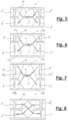
- FIG. 5 An arrangement of exchanger element 1 and packing 4 is shown.
- the exchanger element 1 is assigned a first fan 5, which is arranged downstream of the exchanger element 1 in the supply air flow path 3 and is embedded in the pack 4.
- the exchanger element 1 is assigned a second fan 6, which is arranged upstream or downstream of the exchanger element 1 in the exhaust air flow path 2 and is embedded in the packing 4.
- the exchanger element 1 is assigned a first air filter 7, which is arranged upstream of the exchanger element 1 in the supply air flow path 3 and is embedded in the pack 4.
- the exchanger element 1 is assigned a second air filter 8, which is arranged upstream of the exchanger element 1 in the exhaust air flow path 2 and is embedded in the pack 4.
- the two fans 5 and 6 each work in suction mode.
- Fig. 5 a schematic view of a first arrangement of exchanger element 1 and packing 4 is shown.
- the exchanger element 1 here is a symmetrical countercurrent heat exchanger with a first cross-flow area on the left side and a second cross-flow area on the right side, in which the exhaust air flow path 2 and the supply air flow path 3 intersect.
- a countercurrent area is arranged in between, in which the exhaust air flow path 2 and the supply air flow path 3 are parallel and in opposite directions.
- Fig. 6 a schematic view of a second arrangement of exchanger element 1 and packing 4 is shown.
- the exchanger element 1 here is an asymmetrical countercurrent heat exchanger with a first cross-flow area on the left side and a second cross-flow area on the right side, in which the exhaust air flow path 2 and the supply air flow path 3 intersect.
- a countercurrent area is arranged in between, in which the exhaust air flow path 2 and the supply air flow path 3 are parallel and in opposite directions.
- a first large fan 5 is assigned to a first large outflow area 1a of the exchanger element 1.
- a second large outflow area 1b of the Exchanger element 1 is assigned a second large fan 6.
- a first small air filter 7 is assigned to a first small inflow area 1c of the exchanger element 1.
- a second small air filter 8 is assigned to a second small inflow area 1d of the exchanger element 1.
- Fig. 7 a schematic view of a third arrangement of exchanger element 1 and packing 4 is shown.
- the exchanger element 1 here is also an asymmetrical countercurrent heat exchanger with a first cross-flow area on the left side and a second cross-flow area on the right side, in which the exhaust air flow path 2 and the supply air flow path 3 intersect.
- a countercurrent area is arranged in between, in which the exhaust air flow path 2 and the supply air flow path 3 are parallel and in opposite directions.
- a first small fan 5 is assigned to a first small outflow area 1a of the exchanger element 1.
- a second small fan 6 is assigned to a second small outflow area 1b of the exchanger element 1.
- a first large air filter 7 is assigned to a first large inflow area 1c of the exchanger element 1.
- a second large air filter 8 is assigned to a second large inflow area 1d of the exchanger element 1.
- Fig. 8 a schematic view of a fourth arrangement of exchanger element 1 and packing 4 is shown.
- the exchanger element 1 here is a cross-flow heat exchanger with only one cross-flow area in which the exhaust air flow path 2 and the supply air flow path 3 intersect.
Landscapes
- Engineering & Computer Science (AREA)
- Mechanical Engineering (AREA)
- Physics & Mathematics (AREA)
- Thermal Sciences (AREA)
- General Engineering & Computer Science (AREA)
- Chemical & Material Sciences (AREA)
- Combustion & Propulsion (AREA)
- Air-Conditioning For Vehicles (AREA)
- Heat-Exchange Devices With Radiators And Conduit Assemblies (AREA)
Claims (15)
- Véhicule, un élément échangeur (1) et une emballage (4) étant associés au véhicule, en particulier à une cabine de passagers et/ou à un compartiment moteur du véhicule, dans lequel l'élément échangeur comprenant une trajet d'écoulement d'air d'sortant (2) ainsi qu'une trajet d'écoulement d'air d'entrant (3), et dans lequel la trajet d'écoulement d'air d'sortant et la trajet d'écoulement d'air d'entrant sont séparées l'une de l'autre par des sections de paroi de séparation qui présentent des zones de paroi transmettant la chaleur, dans lequel la trajet d'écoulement d'air d'sortant (2) forme une connexion fluidique depuis l'intérieur du véhicule, en particulier depuis la cabine des passagers ou le compartiment moteur, vers l'environnement extérieur du véhicule, et dans lequel le trajet d'écoulement d'air d'entrant (3) forme une connexion fluidique depuis l'environnement extérieur du véhicule vers un endroit à bord du véhicule, en particulier vers l'intérieur de la cabine passagers et/ou du compartiment moteur, l'élément échangeur (1) étant incorporé dans l'emballage (4) dont la forme de surface extérieure est complémentaire des dimensions intérieures d'un espace de construction à bord du véhicule, en particulier dans la cabine passagers et/ou dans le compartiment moteur, pour le montage de l'élément échangeur (1).
- Véhicule selon la revendication 1, caractérisé en ce que l'emballage (4) comprend un matériau polymère expansé et/ou moussé et/ou un matériau fibreux, en particulier constitué de fibres organiques ou inorganiques, et/ou caractérisé en ce que l'emballage (4) comprend plusieurs parties d'emballage (41, 42).
- Véhicule selon l'une quelconque des revendications 1 ou 2, caractérisé en ce que l'emballage (4) comprend un autre matériau polymère qui enveloppe intérieurement et/ou extérieurement le matériau polymère expansé de l'emballage et dans lequel, de préférence, l'autre matériau polymère est un matériau polymère moins expansé ou un matériau polymère compact non expansé.
- Véhicule selon l'une quelconque des revendications 1 à 3, caractérisé en ce que l'élément échangeur est associé à un premier ventilateur (5) qui est disposé en amont ou en aval de l'élément échangeur dans le trajet d'écoulement d'air d'entrant (3) et qui est incorporé dans l'emballage (4); et/ou caractérisé en ce que l'élément échangeur est associé à un deuxième ventilateur (6) qui est disposé en amont ou en aval de l'élément échangeur dans le trajet d'écoulement d'air d'sortant (2) et qui est incorporé dans l'emballage (4).
- Véhicule selon l'une quelconque des revendications 1 à 4, caractérisé en ce qu'un premier filtre à air (7) est associé à l'élément échangeur, lequel est disposé en amont de l'élément échangeur dans la trajet d'écoulement d'air d'entrant (3) et est incorporé dans l'emballage (4) ; et/ou caractérisé en ce qu'un deuxième filtre à air (8) est associé à l'élément échangeur, lequel est disposé en amont de l'élément échangeur dans la trajet d'écoulement d'air d'sortant (2) et est incorporé dans l'emballage (4).
- Véhicule selon l'une quelconque des revendications 1 à 5, caractérisé en ce que les sections de paroi de séparation présentent des zones de paroi sélectivement perméables à la vapeur d'eau.
- Véhicule selon l'une quelconque des revendications 1 à 6, caractérisé en ce que l'emballage (4) présente des zones d'une première dureté et des zones d'une deuxième dureté, l'emballage (4) présentant de préférence des zones adjacentes à l'élément échangeur d'une plus grande dureté et des zones adjacentes à l'espace de construction d'une plus petite dureté, ou en ce que l'emballage (4) présente des zones adjacentes à l'élément échangeur d'une plus petite dureté et des zones adjacentes à l'espace de construction d'une plus grande dureté.
- Véhicule selon l'une quelconque des revendications précédentes, dans lequel le véhicule est une automobile et l'un des emballages (4) avec un élément échangeur (1) incorporé dans celui-ci est disposé à au moins l'un des emplacements suivants de l'automobile: au plafond de l'habitacle; au toit de l'automobile; à l'avant de l'automobile; dans le montant A de l'automobile; dans le montant B de l'automobile; dans le montant C de l'automobile; à l'arrière de l'automobile; sous le capot de l'automobile; dans le plancher de l'automobile.
- Véhicule selon la revendication 8, caractérisé en ce que la trajet d'écoulement d'air d'sortant (2) est en connexion fluidique avec l'environnement extérieur du véhicule au niveau d'une zone extérieure à basse pression du véhicule; et/ou caractérisé en ce que la trajet d'écoulement d'air d'entrant (3) est en connexion fluidique avec l'environnement extérieur du véhicule au niveau d'une zone extérieure à haute pression du véhicule.
- Véhicule selon l'une quelconque des revendications 8 ou 9, caractérisé en ce que l'élément échangeur (1) comporte un élément chauffage électrique susceptible d'être alimenté par un accumulateur associé à la propulsion électrique ou à la propulsion hybride.
- Procédé de fabrication d'un emballage d'élément échangeur (4) destiné à être disposé dans un espace de construction à bord d'un véhicule, en particulier dans un espace de construction associé à une cabine de passagers et/ou à un compartiment moteur, entre les parois intérieures de l'espace de construction et un élément échangeur (1) à monter dans l'espace de construction, dans lequel le procédé comprenant les étapes suivantes:a) mise à disposition d'un élément échangeur;b) détection des dimensions intérieures de l'espace de construction;c) détection des dimensions extérieures de l'élément échangeur;d) mise à disposition d'un moule avec une cavité de moule, qui est délimitée par une paroi de moule extérieure et une paroi de moule intérieure, la forme de la paroi de moule extérieure étant définie par les dimensions intérieures ou par la paroi de moule intérieure de l'espace de construction et la forme de la paroi intérieure du moule est définie par les dimensions extérieures ou les zones de la paroi extérieure de l'élément échangeur;e) remplissage partiel de la cavité du moule avec un matériau fluide ou coulant;f) expansion ou moussage du matériau fluide ou coolant, dans lequel la cavité du moule étant remplie par le matériau expansé ou mousse; etg) ouverture du moule et retrait du matériau expansé ou moussé de la cavité du moule sous la forme d'un emballage d'élément échangeur (4), après que le matériau expansé ou moussé s'est solidifié.
- Procédé de fabrication d'un emballage d'élément échangeur (4) dans un espace de construction à bord d'un véhicule, en particulier dans un espace de construction associé à une cabine de passagers et/ou à un compartiment moteur, entre les parois intérieures de l'espace de construction et un élément échangeur (1) à monter dans l'espace de construction, dans lequel le procédé comprenant les étapes suivantes:a) mise à disposition d'un élément échangeur;b) mise en place de l'élément échangeur dans l'espace de construction, ce qui permet de définir une cavité de moulage entre les dimensions intérieures ou les zones de paroi intérieure de l'espace de construction et les dimensions extérieures ou les zones de paroi extérieure de l'élément échangeur;c) moussage de la cavité de moule avec un matériau polymère expansible; etd) attendre que le matériau polymère expanse solidifie.
- Procédé de fabrication d'un emballage d'élément échangeur (4) destiné à être disposé dans un espace de construction à bord d'un véhicule, en particulier dans un espace de construction associé à une cabine de passagers et/ou à un compartiment moteur, entre les parois intérieures de l'espace de construction et un élément échangeur (1) à monter dans l'espace de construction, dans lequel le procédé comprenant les étapes suivantes:a) mise à disposition d'un élément échangeur;b) détection des dimensions intérieures de l'espace de construction;c) détection des dimensions extérieures de l'élément échangeur;d) mise à disposition d'un moule avec une cavité de moule, qui est délimitée par une paroi de moule extérieure et une paroi de moule intérieure, la forme de la paroi de moule extérieure étant définie par les dimensions intérieures ou par la paroi de moule intérieure de l'espace de construction et la forme de la paroi intérieure du moule est définie par les dimensions extérieures ou les zones de la paroi extérieure de l'élément échangeur;e) remplir la cavité du moule avec un matériau fondu en injectant le matériau fondu dans la cavité du moule; etf) ouvrir le moule et retirer le matériau injecté de la cavité du moule sous la forme d'un emballage d'élément d'échangeur (4) après que le matériau injecté s'est solidifié.
- Procédé de fabrication d'un emballage d'élément d'échange (4) destiné à être disposé dans un espace de construction à bord d'un véhicule, en particulier dans un espace de construction associé à une cabine de passagers et/ou à un compartiment moteur, entre les parois intérieures de l'espace de construction et un élément d'échangeur (1) à monter dans l'espace de construction, dans lequel le procédé comprenant les étapes suivantes:a) mise à disposition d'un élément d'échangeur;b) disposition de l'élément d'échangeur dans l'espace de construction, ce qui permet de définir une cavité de moulage entre les dimensions intérieures ou les zones de paroi intérieure de l'espace de construction et les dimensions extérieures ou les zones de paroi extérieur de l'élément d'échangeur;c) mise à disposition d'un matériau de construction fusibles en poudre ou à gros grains;d) application d'une couche de matériau de construction comprenant le matériau de construction pulvérulent ou à gros grains sur une surface cible dans une zone de construction au moyen d'un agent d'application;e) application ciblée d'énergie sur des emplacements sélectionnés de la couche de matériau de construction, qui correspondent à une section transversale de l'emballage de l'élément échangeur à former ou de la cavité de moulage à l'intérieur de la couche de matériau de construction, afin de fair fondre le matériau de construction pulvérulent ou à gros grains aux emplacements sélectionnés, etf) le cas échéant, éliminer le matériau de construction pulvérulent ou à gros grains non fondus;dans lequel les étapes d) et e) étant effectuées de manière répétée afin de construire par couches l'emballage d'éléments d'échangeur à former.
- Procédé de fabrication d'un emballage d'élément d'échangeur (4) destiné à être disposé dans un espace de construction d'un véhicule, en particulier dans un espace de construction associé à une cabine de passagers et/ou à un compartiment moteur, entre les parois intérieures de l'espace de construction et un élément d'échangeur (1) à monter dans l'espace de construction, dans lequel le procédé présentant les étapes suivantesa) mise à disposition d'un élément d'échangeur;b) disposition de l'élément d'échangeur dans l'espace de construction, ce qui permet de définir une cavité de moulage entre les dimensions intérieures ou les zones de paroi intérieure de l'espace de construction et les dimensions extérieures ou les zones de paroi extérieur de l'élément d'échangeur;c) mise à disposition d'un matériau de construction liquide ou pâteux, durcissable;d) application ciblée du matériau de construction liquide ou pâteux, durcissable, à des emplacements sélectionnés, en tant que couche de matériau de construction, sur une surface cible dans une zone de construction, à l'aide d'un moyen d'application, la couche de matériau de construction correspondant à une section transversale de l'emballage d'élément échangeur à former ou de la cavité de moulage;e) laisser durcir la couche de matériau de construction afin de solidifier le matériau de construction liquide ou pâteux à l'intérieur de la couche de matériau de construction et de le lier à une couche de matériau de construction appliquée et durcie précédemment;dans lequel les étapes d) et e) étant effectuées de manière répétée afin de construire par couches l'emballage d'éléments échangeur à former.
Applications Claiming Priority (2)
| Application Number | Priority Date | Filing Date | Title |
|---|---|---|---|
| CH4422018 | 2018-04-05 | ||
| PCT/IB2019/052831 WO2019193573A1 (fr) | 2018-04-05 | 2019-04-05 | Élément échangeur pour véhicule ainsi que véhicule équipé dudit élément échangeur |
Publications (3)
| Publication Number | Publication Date |
|---|---|
| EP3781421A1 EP3781421A1 (fr) | 2021-02-24 |
| EP3781421B1 true EP3781421B1 (fr) | 2023-10-11 |
| EP3781421C0 EP3781421C0 (fr) | 2023-10-11 |
Family
ID=66668962
Family Applications (1)
| Application Number | Title | Priority Date | Filing Date |
|---|---|---|---|
| EP19727060.6A Active EP3781421B1 (fr) | 2018-04-05 | 2019-04-05 | Élément échangeur pour véhicule ainsi que véhicule équipé dudit élément échangeur |
Country Status (7)
| Country | Link |
|---|---|
| US (2) | US12203672B2 (fr) |
| EP (1) | EP3781421B1 (fr) |
| JP (1) | JP2021521060A (fr) |
| KR (1) | KR20200141052A (fr) |
| CN (1) | CN112292275A (fr) |
| CA (1) | CA3096238A1 (fr) |
| WO (1) | WO2019193573A1 (fr) |
Families Citing this family (5)
| Publication number | Priority date | Publication date | Assignee | Title |
|---|---|---|---|---|
| US12264884B2 (en) * | 2018-11-05 | 2025-04-01 | Zehnder Group International Ag | Method for providing a heat exchanger block with a housing as well as heat exchanger block having such a housing |
| EP4242536A1 (fr) * | 2022-03-11 | 2023-09-13 | BDR Thermea Group B.V. | Ensemble modulaire de guidage d'air |
| WO2023169927A1 (fr) * | 2022-03-11 | 2023-09-14 | Bdr Thermea Group B.V. | Conduit de guidage d'air |
| DE102023000215A1 (de) * | 2023-01-25 | 2024-07-25 | Achim Rausenberger | Luftführungseinrichtung zum Lüften und Entlüften eines Raumes mit Wärmerückgewinnung |
| US11920821B1 (en) * | 2023-07-31 | 2024-03-05 | Nu-Air Ventilation Systems Incorporated | Energy recovery ventilator |
Family Cites Families (47)
| Publication number | Priority date | Publication date | Assignee | Title |
|---|---|---|---|---|
| FR1165665A (fr) * | 1957-01-23 | 1958-10-28 | Renault | Perfectionnements à l'aération des véhicules |
| US3847211A (en) * | 1969-01-28 | 1974-11-12 | Sub Marine Syst Inc | Property interchange system for fluids |
| JPS4819659B1 (fr) * | 1969-11-04 | 1973-06-15 | ||
| US4016081A (en) * | 1974-04-22 | 1977-04-05 | Baxter Laboratories, Inc. | Staged membrane diffusion device and membrane support |
| US4110220A (en) * | 1976-10-18 | 1978-08-29 | Lavender Ardis R | Mass transfer device |
| JPS57138413A (en) * | 1981-02-18 | 1982-08-26 | Nippon Soken Inc | Air conditioning ventilator for car |
| US4744414A (en) * | 1986-09-02 | 1988-05-17 | Arco Chemical Company | Plastic film plate-type heat exchanger |
| US4742870A (en) * | 1986-10-29 | 1988-05-10 | Cobe Laboratories | Heat exchanger |
| JPS63152782U (fr) * | 1987-03-27 | 1988-10-06 | ||
| DE3806783A1 (de) * | 1988-03-02 | 1989-09-14 | Kiss G H | Instrumententafel |
| FI79810C (fi) * | 1988-03-30 | 1990-03-12 | Kalervo Virtanen | Uppvaermnings- och luftkonditioneringssystem i en buss. |
| JPH04109292U (ja) * | 1991-03-07 | 1992-09-22 | 東洋化学株式会社 | 配管カバー |
| CN2132254Y (zh) * | 1992-06-15 | 1993-05-05 | 胡宗 | 新型干式节能电力变压器 |
| JPH0662613U (ja) * | 1993-01-29 | 1994-09-02 | 株式会社小電力高速通信研究所 | 車載アンテナ |
| JP3651938B2 (ja) * | 1994-10-24 | 2005-05-25 | 松下エコシステムズ株式会社 | 熱交換素子 |
| US20050145372A1 (en) * | 2004-01-02 | 2005-07-07 | Noel Thomas P. | Method and thermally active multi-phase heat transfer apparatus and method for abstracting heat using liquid bi-phase heat exchanging composition |
| US7055575B2 (en) * | 2002-10-18 | 2006-06-06 | Noel Thomas P | Thermally active convection apparatus |
| DE10106045A1 (de) * | 2001-02-09 | 2002-08-29 | Christian Mueller | Formteil aus geschäumtem Kunststoff für ein Fahrzeugausstattungsteil |
| US6648860B2 (en) | 2001-07-13 | 2003-11-18 | Liebel-Flarsheim Company | Contrast delivery syringe with internal hydrophilic surface treatment for the prevention of bubble adhesion |
| DK176335B1 (da) * | 2001-11-13 | 2007-08-20 | Siemens Wind Power As | Fremgangsmåde til fremstilling af vindmöllevinger |
| US7225286B2 (en) | 2002-06-24 | 2007-05-29 | Koninklijke Philips Electronics N.V. | Method to measure transmission delay between 1394 bridges |
| CN2550203Y (zh) * | 2002-06-28 | 2003-05-14 | 温州奥乐安全器材有限公司 | 嵌入式警报控制装置 |
| US20050044712A1 (en) * | 2003-08-28 | 2005-03-03 | Gideon David E. | Sidewall panel integrated with insulation and air ducts |
| EP1704377B1 (fr) * | 2003-10-14 | 2008-01-02 | LG Electronics, Inc. | Echangeur thermique destine a un ventilateur |
| JP4529799B2 (ja) * | 2005-06-01 | 2010-08-25 | 株式会社デンソー | 空調ユニット |
| AU2005337364A1 (en) * | 2005-10-14 | 2007-04-19 | Truma Geratetechnick Gmbh & Co. Kg | Air-conditioning unit for mobile devices |
| WO2008041327A1 (fr) * | 2006-10-03 | 2008-04-10 | Mitsubishi Electric Corporation | Élément d'échange thermique total et appareil d'échange thermique total |
| KR20080060932A (ko) * | 2006-12-27 | 2008-07-02 | 엘지전자 주식회사 | 환기 장치의 열교환기 |
| WO2009020679A2 (fr) * | 2007-05-02 | 2009-02-12 | Creare Inc. | Echangeur de chaleur/masse flexible |
| CA2720692C (fr) * | 2008-04-08 | 2016-10-04 | Formway Furniture Limited | Procede de moulage par injection |
| DE102009014377A1 (de) * | 2009-03-23 | 2010-09-30 | Airbus Deutschland Gmbh | Flugzeugstruktur mit in Strukturelemente integrierte Luftführungsschächte |
| FR2962711B1 (fr) * | 2010-07-13 | 2013-03-29 | Airbus Operations Sas | Dispositif de revetement interieur d'une cabine d'aeronef integrant au moins un systeme. |
| DE102011085667A1 (de) * | 2011-11-03 | 2013-05-08 | Robert Bosch Gmbh | Klimatisierungseinrichtung sowie Kraftfahrzeug |
| WO2013091099A1 (fr) * | 2011-12-19 | 2013-06-27 | Dpoint Technologies Inc. | Noyau de ventilateur à récupération d'énergie (erv) à contre-courant |
| DE102013021066A1 (de) * | 2013-12-18 | 2015-06-18 | Airbus Defence and Space GmbH | Herstellverfahren zum Herstellen eines tragenden Rumpfpaneels sowie damit herstellbares Rumpfpaneel |
| US9446540B2 (en) * | 2014-05-06 | 2016-09-20 | Ford Global Technologies, Llc | Hybrid composite utilizing injection-expansion molding |
| JP2016023909A (ja) * | 2014-07-24 | 2016-02-08 | 富士電機株式会社 | 車載用の冷却ユニットおよび冷凍車 |
| MX2016005813A (es) * | 2015-05-13 | 2016-11-14 | Ford Global Tech Llc | Compuesto hibrido que utiliza moldeo por inyeccion-expansion. |
| JP2017026561A (ja) * | 2015-07-28 | 2017-02-02 | 株式会社オプティコン | 筐体、装置、照明装置、同軸照明装置及び筐体の製造方法 |
| EP3124375B1 (fr) * | 2015-07-29 | 2018-05-09 | Airbus Operations GmbH | Élément de panneau |
| DE102015115196B4 (de) * | 2015-09-09 | 2021-10-21 | Denso Automotive Deutschland Gmbh | Belüftungsanlage für ein Kraftfahrzeug und dazugehöriges Steuerungsverfahren |
| JP6390574B2 (ja) * | 2015-09-29 | 2018-09-19 | マツダ株式会社 | 変速機及びその製造方法 |
| CN107759056A (zh) * | 2016-01-26 | 2018-03-06 | 广东欧珀移动通信有限公司 | 一种盖板玻璃模具 |
| US12264884B2 (en) * | 2018-11-05 | 2025-04-01 | Zehnder Group International Ag | Method for providing a heat exchanger block with a housing as well as heat exchanger block having such a housing |
| KR101995250B1 (ko) * | 2018-12-05 | 2019-07-02 | 이응기 | 공압출 발포 공법으로 제조되는 다층구조의 폴리락트산 수지 발포 성형품 및 그 제조방법 |
| FR3090573A1 (fr) * | 2018-12-20 | 2020-06-26 | Airbus Operations | Panneau de revêtement mural pour aéronef à isolation intégrée |
| US11999086B2 (en) * | 2021-09-28 | 2024-06-04 | Spirit Aerosystems, Inc. | System for forming a composite part |
-
2019
- 2019-04-05 KR KR1020207030409A patent/KR20200141052A/ko not_active Ceased
- 2019-04-05 US US17/045,331 patent/US12203672B2/en active Active
- 2019-04-05 CN CN201980037435.4A patent/CN112292275A/zh active Pending
- 2019-04-05 JP JP2021503226A patent/JP2021521060A/ja active Pending
- 2019-04-05 CA CA3096238A patent/CA3096238A1/fr active Pending
- 2019-04-05 EP EP19727060.6A patent/EP3781421B1/fr active Active
- 2019-04-05 WO PCT/IB2019/052831 patent/WO2019193573A1/fr not_active Ceased
-
2024
- 2024-07-12 US US18/771,233 patent/US20240393000A1/en active Pending
Also Published As
| Publication number | Publication date |
|---|---|
| JP2021521060A (ja) | 2021-08-26 |
| CA3096238A1 (fr) | 2019-10-10 |
| CN112292275A (zh) | 2021-01-29 |
| US20210148597A1 (en) | 2021-05-20 |
| US20240393000A1 (en) | 2024-11-28 |
| KR20200141052A (ko) | 2020-12-17 |
| WO2019193573A1 (fr) | 2019-10-10 |
| US12203672B2 (en) | 2025-01-21 |
| EP3781421A1 (fr) | 2021-02-24 |
| EP3781421C0 (fr) | 2023-10-11 |
Similar Documents
| Publication | Publication Date | Title |
|---|---|---|
| EP3781421B1 (fr) | Élément échangeur pour véhicule ainsi que véhicule équipé dudit élément échangeur | |
| EP3022093B1 (fr) | Tableau de bord d'un vehicule | |
| EP3393743B1 (fr) | Procédé pour fabriquer un corps moulé à partir d'une matière de mousse particulaire | |
| DE102012216039B4 (de) | Gehäuse für eine Klimaanlage | |
| DE69826218T2 (de) | Kraftstofftank | |
| DE19620919A1 (de) | Instrumententafel für ein Kraftfahrzeug | |
| EP0865462B1 (fr) | Procede de fabrication d'un materiau realise a partir de perles de plastique | |
| DE112008002904T5 (de) | Asymmetrische Membran und Klimatisierungssystem, bei dem die asymmetrische Membran eingesetzt wird | |
| DE102004004237B4 (de) | Verfahren zur Herstellung von mikroporösen Kunststoffprodukten und die nach diesem Verfahren erhältlichen Formteile, Profile und Granulate | |
| WO2018028740A1 (fr) | Capsule insonorisante d'un bloc moteur de soufflerie d'un aspirateur, ainsi qu'aspirateur | |
| DE102010021123A1 (de) | Formteil und Verfahren zur Herstellung eines Formteils, insbesondere eines Formteils für ein Kraftfahrzeug, wie ein Armaturenbrett oder eine Mittelkonsole | |
| EP0596234A1 (fr) | Panneau pour la garniture intérieure de pavillon d'une voiture ou d'un petit bus | |
| DE102011106749A1 (de) | Verfahren zur Herstellung eines Gassackpakets | |
| EP1502726B1 (fr) | Matériaux pour moulages | |
| DE20112186U1 (de) | Formteil für ein Auskleidungsteil für den Fahrzeuginnenraum aus geschäumtem Kunststoff | |
| DE102013208235A1 (de) | Verfahren zum Sprühbeschichten | |
| DE10237366A1 (de) | Schallisolierendes Material und Verfahren zu dessen Herstellung | |
| DE102013207973A1 (de) | Aktivpolster mit Gasleitkanälen | |
| DE102004031414B4 (de) | Verfahren zur Herstellung eines Innenausstattungssystems | |
| DE102023135666A1 (de) | Geformte platte und fertigung davon | |
| DE102004004548B4 (de) | Verkleidungselement und Verfahren zu dessen Herstellung | |
| DE10106045A1 (de) | Formteil aus geschäumtem Kunststoff für ein Fahrzeugausstattungsteil | |
| DE102005049836B4 (de) | Fahrzeugverkleidungsanordnung mit Aufprallschutzstrukturen und Verfahren zum Herstellen derselben | |
| EP1479547A1 (fr) | Boítier, notamment boítier de guidage d'air, et sa méthode de fabrication | |
| DE10257754A1 (de) | Luftausströmvorrichtung und Verfahren zu deren Herstellung |
Legal Events
| Date | Code | Title | Description |
|---|---|---|---|
| STAA | Information on the status of an ep patent application or granted ep patent |
Free format text: STATUS: THE INTERNATIONAL PUBLICATION HAS BEEN MADE |
|
| PUAI | Public reference made under article 153(3) epc to a published international application that has entered the european phase |
Free format text: ORIGINAL CODE: 0009012 |
|
| STAA | Information on the status of an ep patent application or granted ep patent |
Free format text: STATUS: REQUEST FOR EXAMINATION WAS MADE |
|
| 17P | Request for examination filed |
Effective date: 20201015 |
|
| AK | Designated contracting states |
Kind code of ref document: A1 Designated state(s): AL AT BE BG CH CY CZ DE DK EE ES FI FR GB GR HR HU IE IS IT LI LT LU LV MC MK MT NL NO PL PT RO RS SE SI SK SM TR |
|
| AX | Request for extension of the european patent |
Extension state: BA ME |
|
| DAV | Request for validation of the european patent (deleted) | ||
| DAX | Request for extension of the european patent (deleted) | ||
| STAA | Information on the status of an ep patent application or granted ep patent |
Free format text: STATUS: EXAMINATION IS IN PROGRESS |
|
| 17Q | First examination report despatched |
Effective date: 20220228 |
|
| GRAP | Despatch of communication of intention to grant a patent |
Free format text: ORIGINAL CODE: EPIDOSNIGR1 |
|
| STAA | Information on the status of an ep patent application or granted ep patent |
Free format text: STATUS: GRANT OF PATENT IS INTENDED |
|
| INTG | Intention to grant announced |
Effective date: 20230519 |
|
| GRAS | Grant fee paid |
Free format text: ORIGINAL CODE: EPIDOSNIGR3 |
|
| GRAA | (expected) grant |
Free format text: ORIGINAL CODE: 0009210 |
|
| STAA | Information on the status of an ep patent application or granted ep patent |
Free format text: STATUS: THE PATENT HAS BEEN GRANTED |
|
| AK | Designated contracting states |
Kind code of ref document: B1 Designated state(s): AL AT BE BG CH CY CZ DE DK EE ES FI FR GB GR HR HU IE IS IT LI LT LU LV MC MK MT NL NO PL PT RO RS SE SI SK SM TR |
|
| REG | Reference to a national code |
Ref country code: GB Ref legal event code: FG4D Free format text: NOT ENGLISH |
|
| REG | Reference to a national code |
Ref country code: CH Ref legal event code: EP |
|
| REG | Reference to a national code |
Ref country code: DE Ref legal event code: R096 Ref document number: 502019009636 Country of ref document: DE |
|
| REG | Reference to a national code |
Ref country code: IE Ref legal event code: FG4D Free format text: LANGUAGE OF EP DOCUMENT: GERMAN |
|
| U01 | Request for unitary effect filed |
Effective date: 20231011 |
|
| U07 | Unitary effect registered |
Designated state(s): AT BE BG DE DK EE FI FR IT LT LU LV MT NL PT SE SI Effective date: 20231016 |
|
| PG25 | Lapsed in a contracting state [announced via postgrant information from national office to epo] |
Ref country code: GR Free format text: LAPSE BECAUSE OF FAILURE TO SUBMIT A TRANSLATION OF THE DESCRIPTION OR TO PAY THE FEE WITHIN THE PRESCRIBED TIME-LIMIT Effective date: 20240112 |
|
| PG25 | Lapsed in a contracting state [announced via postgrant information from national office to epo] |
Ref country code: IS Free format text: LAPSE BECAUSE OF FAILURE TO SUBMIT A TRANSLATION OF THE DESCRIPTION OR TO PAY THE FEE WITHIN THE PRESCRIBED TIME-LIMIT Effective date: 20240211 |
|
| PG25 | Lapsed in a contracting state [announced via postgrant information from national office to epo] |
Ref country code: ES Free format text: LAPSE BECAUSE OF FAILURE TO SUBMIT A TRANSLATION OF THE DESCRIPTION OR TO PAY THE FEE WITHIN THE PRESCRIBED TIME-LIMIT Effective date: 20231011 |
|
| PG25 | Lapsed in a contracting state [announced via postgrant information from national office to epo] |
Ref country code: IS Free format text: LAPSE BECAUSE OF FAILURE TO SUBMIT A TRANSLATION OF THE DESCRIPTION OR TO PAY THE FEE WITHIN THE PRESCRIBED TIME-LIMIT Effective date: 20240211 Ref country code: GR Free format text: LAPSE BECAUSE OF FAILURE TO SUBMIT A TRANSLATION OF THE DESCRIPTION OR TO PAY THE FEE WITHIN THE PRESCRIBED TIME-LIMIT Effective date: 20240112 Ref country code: ES Free format text: LAPSE BECAUSE OF FAILURE TO SUBMIT A TRANSLATION OF THE DESCRIPTION OR TO PAY THE FEE WITHIN THE PRESCRIBED TIME-LIMIT Effective date: 20231011 |
|
| U20 | Renewal fee for the european patent with unitary effect paid |
Year of fee payment: 6 Effective date: 20240424 |
|
| PG25 | Lapsed in a contracting state [announced via postgrant information from national office to epo] |
Ref country code: RS Free format text: LAPSE BECAUSE OF FAILURE TO SUBMIT A TRANSLATION OF THE DESCRIPTION OR TO PAY THE FEE WITHIN THE PRESCRIBED TIME-LIMIT Effective date: 20231011 Ref country code: PL Free format text: LAPSE BECAUSE OF FAILURE TO SUBMIT A TRANSLATION OF THE DESCRIPTION OR TO PAY THE FEE WITHIN THE PRESCRIBED TIME-LIMIT Effective date: 20231011 Ref country code: NO Free format text: LAPSE BECAUSE OF FAILURE TO SUBMIT A TRANSLATION OF THE DESCRIPTION OR TO PAY THE FEE WITHIN THE PRESCRIBED TIME-LIMIT Effective date: 20240111 Ref country code: HR Free format text: LAPSE BECAUSE OF FAILURE TO SUBMIT A TRANSLATION OF THE DESCRIPTION OR TO PAY THE FEE WITHIN THE PRESCRIBED TIME-LIMIT Effective date: 20231011 |
|
| REG | Reference to a national code |
Ref country code: DE Ref legal event code: R097 Ref document number: 502019009636 Country of ref document: DE |
|
| PG25 | Lapsed in a contracting state [announced via postgrant information from national office to epo] |
Ref country code: CZ Free format text: LAPSE BECAUSE OF FAILURE TO SUBMIT A TRANSLATION OF THE DESCRIPTION OR TO PAY THE FEE WITHIN THE PRESCRIBED TIME-LIMIT Effective date: 20231011 |
|
| PG25 | Lapsed in a contracting state [announced via postgrant information from national office to epo] |
Ref country code: SK Free format text: LAPSE BECAUSE OF FAILURE TO SUBMIT A TRANSLATION OF THE DESCRIPTION OR TO PAY THE FEE WITHIN THE PRESCRIBED TIME-LIMIT Effective date: 20231011 |
|
| PG25 | Lapsed in a contracting state [announced via postgrant information from national office to epo] |
Ref country code: SM Free format text: LAPSE BECAUSE OF FAILURE TO SUBMIT A TRANSLATION OF THE DESCRIPTION OR TO PAY THE FEE WITHIN THE PRESCRIBED TIME-LIMIT Effective date: 20231011 Ref country code: SK Free format text: LAPSE BECAUSE OF FAILURE TO SUBMIT A TRANSLATION OF THE DESCRIPTION OR TO PAY THE FEE WITHIN THE PRESCRIBED TIME-LIMIT Effective date: 20231011 Ref country code: RO Free format text: LAPSE BECAUSE OF FAILURE TO SUBMIT A TRANSLATION OF THE DESCRIPTION OR TO PAY THE FEE WITHIN THE PRESCRIBED TIME-LIMIT Effective date: 20231011 Ref country code: CZ Free format text: LAPSE BECAUSE OF FAILURE TO SUBMIT A TRANSLATION OF THE DESCRIPTION OR TO PAY THE FEE WITHIN THE PRESCRIBED TIME-LIMIT Effective date: 20231011 |
|
| PLBE | No opposition filed within time limit |
Free format text: ORIGINAL CODE: 0009261 |
|
| STAA | Information on the status of an ep patent application or granted ep patent |
Free format text: STATUS: NO OPPOSITION FILED WITHIN TIME LIMIT |
|
| 26N | No opposition filed |
Effective date: 20240712 |
|
| PG25 | Lapsed in a contracting state [announced via postgrant information from national office to epo] |
Ref country code: MC Free format text: LAPSE BECAUSE OF FAILURE TO SUBMIT A TRANSLATION OF THE DESCRIPTION OR TO PAY THE FEE WITHIN THE PRESCRIBED TIME-LIMIT Effective date: 20231011 |
|
| PG25 | Lapsed in a contracting state [announced via postgrant information from national office to epo] |
Ref country code: MC Free format text: LAPSE BECAUSE OF FAILURE TO SUBMIT A TRANSLATION OF THE DESCRIPTION OR TO PAY THE FEE WITHIN THE PRESCRIBED TIME-LIMIT Effective date: 20231011 |
|
| PG25 | Lapsed in a contracting state [announced via postgrant information from national office to epo] |
Ref country code: IE Free format text: LAPSE BECAUSE OF NON-PAYMENT OF DUE FEES Effective date: 20240405 |
|
| U20 | Renewal fee for the european patent with unitary effect paid |
Year of fee payment: 7 Effective date: 20250425 |
|
| PGFP | Annual fee paid to national office [announced via postgrant information from national office to epo] |
Ref country code: GB Payment date: 20250423 Year of fee payment: 7 |
|
| PGFP | Annual fee paid to national office [announced via postgrant information from national office to epo] |
Ref country code: CH Payment date: 20250501 Year of fee payment: 7 |
|
| PG25 | Lapsed in a contracting state [announced via postgrant information from national office to epo] |
Ref country code: CY Free format text: LAPSE BECAUSE OF FAILURE TO SUBMIT A TRANSLATION OF THE DESCRIPTION OR TO PAY THE FEE WITHIN THE PRESCRIBED TIME-LIMIT; INVALID AB INITIO Effective date: 20190405 |
|
| PG25 | Lapsed in a contracting state [announced via postgrant information from national office to epo] |
Ref country code: HU Free format text: LAPSE BECAUSE OF FAILURE TO SUBMIT A TRANSLATION OF THE DESCRIPTION OR TO PAY THE FEE WITHIN THE PRESCRIBED TIME-LIMIT; INVALID AB INITIO Effective date: 20190405 |
|
| PG25 | Lapsed in a contracting state [announced via postgrant information from national office to epo] |
Ref country code: TR Free format text: LAPSE BECAUSE OF FAILURE TO SUBMIT A TRANSLATION OF THE DESCRIPTION OR TO PAY THE FEE WITHIN THE PRESCRIBED TIME-LIMIT Effective date: 20231011 |