EP3781445B1 - Système de freinage hydrauliquement ouvert à plusieurs circuits, notamment pour véhicule autonome ou fortement automatisé - Google Patents
Système de freinage hydrauliquement ouvert à plusieurs circuits, notamment pour véhicule autonome ou fortement automatisé Download PDFInfo
- Publication number
- EP3781445B1 EP3781445B1 EP19718593.7A EP19718593A EP3781445B1 EP 3781445 B1 EP3781445 B1 EP 3781445B1 EP 19718593 A EP19718593 A EP 19718593A EP 3781445 B1 EP3781445 B1 EP 3781445B1
- Authority
- EP
- European Patent Office
- Prior art keywords
- brake
- pressure
- valve
- shut
- pressure generator
- Prior art date
- Legal status (The legal status is an assumption and is not a legal conclusion. Google has not performed a legal analysis and makes no representation as to the accuracy of the status listed.)
- Active
Links
Images



Classifications
-
- B—PERFORMING OPERATIONS; TRANSPORTING
- B60—VEHICLES IN GENERAL
- B60T—VEHICLE BRAKE CONTROL SYSTEMS OR PARTS THEREOF; BRAKE CONTROL SYSTEMS OR PARTS THEREOF, IN GENERAL; ARRANGEMENT OF BRAKING ELEMENTS ON VEHICLES IN GENERAL; PORTABLE DEVICES FOR PREVENTING UNWANTED MOVEMENT OF VEHICLES; VEHICLE MODIFICATIONS TO FACILITATE COOLING OF BRAKES
- B60T13/00—Transmitting braking action from initiating means to ultimate brake actuator with power assistance or drive; Brake systems incorporating such transmitting means, e.g. air-pressure brake systems
- B60T13/10—Transmitting braking action from initiating means to ultimate brake actuator with power assistance or drive; Brake systems incorporating such transmitting means, e.g. air-pressure brake systems with fluid assistance, drive, or release
- B60T13/12—Transmitting braking action from initiating means to ultimate brake actuator with power assistance or drive; Brake systems incorporating such transmitting means, e.g. air-pressure brake systems with fluid assistance, drive, or release the fluid being liquid
- B60T13/14—Transmitting braking action from initiating means to ultimate brake actuator with power assistance or drive; Brake systems incorporating such transmitting means, e.g. air-pressure brake systems with fluid assistance, drive, or release the fluid being liquid using accumulators or reservoirs fed by pumps
- B60T13/148—Arrangements for pressure supply
-
- B—PERFORMING OPERATIONS; TRANSPORTING
- B60—VEHICLES IN GENERAL
- B60T—VEHICLE BRAKE CONTROL SYSTEMS OR PARTS THEREOF; BRAKE CONTROL SYSTEMS OR PARTS THEREOF, IN GENERAL; ARRANGEMENT OF BRAKING ELEMENTS ON VEHICLES IN GENERAL; PORTABLE DEVICES FOR PREVENTING UNWANTED MOVEMENT OF VEHICLES; VEHICLE MODIFICATIONS TO FACILITATE COOLING OF BRAKES
- B60T8/00—Arrangements for adjusting wheel-braking force to meet varying vehicular or ground-surface conditions, e.g. limiting or varying distribution of braking force
- B60T8/32—Arrangements for adjusting wheel-braking force to meet varying vehicular or ground-surface conditions, e.g. limiting or varying distribution of braking force responsive to a speed condition, e.g. acceleration or deceleration
- B60T8/321—Arrangements for adjusting wheel-braking force to meet varying vehicular or ground-surface conditions, e.g. limiting or varying distribution of braking force responsive to a speed condition, e.g. acceleration or deceleration deceleration
- B60T8/3255—Systems in which the braking action is dependent on brake pedal data
- B60T8/326—Hydraulic systems
-
- B—PERFORMING OPERATIONS; TRANSPORTING
- B60—VEHICLES IN GENERAL
- B60T—VEHICLE BRAKE CONTROL SYSTEMS OR PARTS THEREOF; BRAKE CONTROL SYSTEMS OR PARTS THEREOF, IN GENERAL; ARRANGEMENT OF BRAKING ELEMENTS ON VEHICLES IN GENERAL; PORTABLE DEVICES FOR PREVENTING UNWANTED MOVEMENT OF VEHICLES; VEHICLE MODIFICATIONS TO FACILITATE COOLING OF BRAKES
- B60T13/00—Transmitting braking action from initiating means to ultimate brake actuator with power assistance or drive; Brake systems incorporating such transmitting means, e.g. air-pressure brake systems
- B60T13/10—Transmitting braking action from initiating means to ultimate brake actuator with power assistance or drive; Brake systems incorporating such transmitting means, e.g. air-pressure brake systems with fluid assistance, drive, or release
- B60T13/66—Electrical control in fluid-pressure brake systems
- B60T13/68—Electrical control in fluid-pressure brake systems by electrically-controlled valves
- B60T13/686—Electrical control in fluid-pressure brake systems by electrically-controlled valves in hydraulic systems or parts thereof
-
- B—PERFORMING OPERATIONS; TRANSPORTING
- B60—VEHICLES IN GENERAL
- B60T—VEHICLE BRAKE CONTROL SYSTEMS OR PARTS THEREOF; BRAKE CONTROL SYSTEMS OR PARTS THEREOF, IN GENERAL; ARRANGEMENT OF BRAKING ELEMENTS ON VEHICLES IN GENERAL; PORTABLE DEVICES FOR PREVENTING UNWANTED MOVEMENT OF VEHICLES; VEHICLE MODIFICATIONS TO FACILITATE COOLING OF BRAKES
- B60T8/00—Arrangements for adjusting wheel-braking force to meet varying vehicular or ground-surface conditions, e.g. limiting or varying distribution of braking force
- B60T8/32—Arrangements for adjusting wheel-braking force to meet varying vehicular or ground-surface conditions, e.g. limiting or varying distribution of braking force responsive to a speed condition, e.g. acceleration or deceleration
- B60T8/321—Arrangements for adjusting wheel-braking force to meet varying vehicular or ground-surface conditions, e.g. limiting or varying distribution of braking force responsive to a speed condition, e.g. acceleration or deceleration deceleration
-
- B—PERFORMING OPERATIONS; TRANSPORTING
- B60—VEHICLES IN GENERAL
- B60T—VEHICLE BRAKE CONTROL SYSTEMS OR PARTS THEREOF; BRAKE CONTROL SYSTEMS OR PARTS THEREOF, IN GENERAL; ARRANGEMENT OF BRAKING ELEMENTS ON VEHICLES IN GENERAL; PORTABLE DEVICES FOR PREVENTING UNWANTED MOVEMENT OF VEHICLES; VEHICLE MODIFICATIONS TO FACILITATE COOLING OF BRAKES
- B60T8/00—Arrangements for adjusting wheel-braking force to meet varying vehicular or ground-surface conditions, e.g. limiting or varying distribution of braking force
- B60T8/32—Arrangements for adjusting wheel-braking force to meet varying vehicular or ground-surface conditions, e.g. limiting or varying distribution of braking force responsive to a speed condition, e.g. acceleration or deceleration
- B60T8/88—Arrangements for adjusting wheel-braking force to meet varying vehicular or ground-surface conditions, e.g. limiting or varying distribution of braking force responsive to a speed condition, e.g. acceleration or deceleration with failure responsive means, i.e. means for detecting and indicating faulty operation of the speed responsive control means
- B60T8/885—Arrangements for adjusting wheel-braking force to meet varying vehicular or ground-surface conditions, e.g. limiting or varying distribution of braking force responsive to a speed condition, e.g. acceleration or deceleration with failure responsive means, i.e. means for detecting and indicating faulty operation of the speed responsive control means using electrical circuitry
Definitions
- the invention is based on a multi-circuit, hydraulically open brake system without mechanical and/or hydraulic intervention by the driver, in particular for a highly automated or autonomous vehicle, according to the generic type of independent patent claim 1.
- the subject matter of the present invention is also an operating method for such a multi-circuit hydraulically Open brake system without mechanical and/or hydraulic intervention by the driver. So a braking system and operating method is out of the US 2016/009267 A1 known.
- Vehicles with at least one highly automated or autonomous driving function are known from the prior art, which can at least partially take over an actual driving task.
- This allows the vehicles to drive highly automated or autonomously, for example by the vehicles independently recognizing the course of the road, other road users or obstacles and calculating the corresponding control commands in the vehicle and forwarding them to the actuators in the vehicle, which correctly influences the vehicle's driving process.
- the driver is usually not involved in driving. Nevertheless, measures and means are provided which enable the driver to be able to intervene in the driving process himself at any time.
- brake systems for vehicles are known from the prior art, which are designed to be controlled by a vehicle driver with hydraulic penetration. This ensures that if the braking system fails, the driver can still apply sufficient braking force to the wheels of the vehicle by pressing the brake pedal.
- This interpretation significantly influences the topology of today's brake systems. For example, the size of a tandem brake master cylinder can be justified by maintaining good performance in the backup level.
- the braking systems can be designed as so-called coupled braking systems or power-assisted braking systems. However, these systems are also implemented in such a way that the driver can still intervene hydraulically as a fallback. Auxiliary power brake systems are unsuitable for highly automated or autonomous vehicles, since there is no longer a driver to assist during an autonomous driving function and the braking system has to build up the braking energy completely independently.
- the hydraulic brake system includes a master brake cylinder, at least one wheel brake cylinder, a first brake pressure generator and a second brake pressure generator.
- the master brake cylinder can be hydraulically connected to the at least one wheel brake cylinder via the second brake pressure generator.
- the first brake pressure generator and the second brake pressure generator can be connected hydraulically in parallel or in series between the master brake cylinder and the at least one wheel brake cylinder.
- the vehicle brake system includes an electromechanical brake booster and wheel slip control.
- the vehicle brake system is actuated with the brake booster in situations in which a brake pedal is not actuated, for example to limit a vehicle speed or to regulate the distance from a vehicle driving ahead or when parking.
- the brake systems each include four wheel brakes, each of which is assigned to a brake circuit with a pressure relief path, and two power-operated pressure generators and one muscle-power-operated Pressure generators, which are hydraulically connected in parallel between at least one fluid container and the wheel brakes, and a modulation unit for hydraulically connecting the pressure generators to the four wheel brakes and for individual brake pressure modulation in the four wheel brakes.
- the brake system comprises four wheel brakes, each of which is assigned to a brake circuit with a pressure relief path, two power-operated pressure generators, which are hydraulically connected in parallel between at least one fluid container and the wheel brakes, and a modulation unit for hydraulically connecting the pressure generators to the four wheel brakes and for individual brake pressure modulation in the four wheel brakes.
- a first of the two power-operated pressure generators is assigned to a main system which includes a first energy supply and a first evaluation and control unit.
- a second of the power-operated pressure generators is assigned to a secondary system, which includes a second energy supply that is independent of the first energy supply and a second evaluation and control unit.
- the second evaluation and control unit controls the second pressure generator, with components of the modulation unit being assigned to the main system for individual brake pressure modulation, so that these components of the modulation unit and the first pressure generator are controlled by the first evaluation and control unit and supplied with energy from the first energy supply become.
- the two pressure generators can be connected to the four wheel brakes via four common shut-off valves.
- the multi-circuit, hydraulically open brake system without mechanical and/or hydraulic intervention by the driver, in particular for a highly automated or autonomous vehicle, with the features of independent claim 1 and the corresponding operating method for such a multi-circuit, hydraulically open brake system without mechanical and/or hydraulic intervention the driver with the features of independent claim 15 have the advantage that a simple, robust and cost-effective braking system architecture is provided without mechanical and/or hydraulic intervention by the driver, which enables adequate braking performance even in the event of a fault through a suitable redundancy concept.
- Embodiments of the invention have fewer components than known braking systems because fewer valves, no pedal travel simulator, no mechanism to generate, amplify and transmit driver pressure are required, resulting in lower braking system costs. In addition, the system costs are lower because there is only one hydraulic connection on the wheel brakes and no alternative solutions with two connections in the brake caliper are required, which act on different pistons.
- Embodiments of the present invention provide a multi-circuit, hydraulically open brake system without mechanical and/or hydraulic intervention by the driver, in particular for a highly automated or autonomous vehicle, with at least two wheel brakes, which are each assigned to a brake circuit with a pressure relief path, two pressure generators, which are between at least a fluid reservoir and the at least two wheel brakes are connected hydraulically in parallel, and a modulation unit for hydraulically connecting the pressure generator to the at least two wheel brakes and for individual brake pressure modulation in the at least two wheel brakes.
- a first pressure generator is assigned to a main system, which includes a first energy supply and a first evaluation and control unit, and can be connected to at least one wheel brake of a first brake circuit via a first shut-off valve and to at least one wheel brake of a second brake circuit via a second shut-off valve.
- a second pressure generator is assigned to a secondary system, which includes a second energy supply independent of the first energy supply and a second evaluation and control unit, and via a third shut-off valve with at least one wheel brake of the first brake circuit and via a fourth shut-off valve with at least one wheel brake of the second brake circuit connectable.
- the second evaluation and control unit controls the second pressure generator, with components of the modulation unit being assigned to the main system for individual brake pressure modulation, so that these components of the modulation unit and the first pressure generator are controlled by the first evaluation and control unit and supplied with energy from the first energy supply become.
- the shut-off valves are controlled by the first evaluation and control unit and/or by the second evaluation and control unit in such a way that when one of the two pressure generators is activated, hydraulic fluid is not passed through the other of the two pressure generators.
- an operating method for such a multi-circuit, hydraulically open brake system without mechanical and/or hydraulic intervention by the driver, in particular for a highly automated or autonomous vehicle is proposed.
- the main system increases or reduces or maintains the pressure in the brake circuits by means of the first pressure generator and carries out the individual brake pressure modulation in the at least two wheel brakes by means of the modulation unit. If the main system fails, the secondary system increases or reduces or maintains the pressure in the brake circuits by means of the second pressure generator, and the individual brake pressure modulation in the at least two wheel brakes is omitted.
- a hydraulically open brake system is understood to mean a brake system in which during an individual brake pressure modulation drained brake fluid can be returned from the wheel brakes via a pressure relief path to the fluid reservoir.
- control functions such as anti-lock control ABS, traction control ASR, driving dynamics control FDR or ESP can be implemented in an advantageous manner for longitudinal and lateral stabilization of the vehicle. Since these control functions are known per se, they will not be discussed in any more detail here.
- the evaluation and control unit can be understood to mean an electrical device, such as a control unit, which processes or evaluates detected sensor signals.
- the evaluation and control unit can have at least one interface, which can be in the form of hardware and/or software.
- the interfaces can be part of a so-called system ASIC, for example, which contains a wide variety of functions of the evaluation and control unit.
- the interfaces can be separate integrated circuits or to consist at least partially of discrete components.
- the interfaces can be software modules which are present, for example, on a microcontroller alongside other software modules.
- a computer program product with program code is also advantageous, which is stored on a machine-readable carrier such as a semiconductor memory, a hard disk memory or an optical memory and is used to carry out the evaluation when the program is executed by the evaluation and control unit.
- Sensor units are provided for detecting the sensor signals, which in the present case are assemblies that include at least one sensor element that directly or indirectly detects a physical variable or a change in a physical variable and preferably converts it into an electrical sensor signal. This can be done, for example, by sending out and/or receiving sound waves and/or electromagnetic waves and/or using a magnetic field or changing a magnetic field and/or receiving satellite signals, for example a GPS signal take place.
- a sensor unit can include, for example, acceleration sensor elements that record acceleration-relevant information from the vehicle and/or sensor elements that determine objects and/or obstacles and/or other crash-relevant vehicle environment data and make it available for evaluation.
- Such sensor elements can be based, for example, on video and/or radar and/or lidar and/or PMD and/or ultrasound technologies.
- signals and information from an existing ABS sensor system and the variables derived in the control unit provided for this purpose can also be evaluated.
- GNSS Global Navigation Satellite System
- NAVSTAR GPS Global Positioning System
- GLONASS Global Navigation Satellite System
- Galileo of the European Union
- Beidou of the People's Republic of China
- a highly automated or autonomous vehicle is understood to mean a vehicle which has at least one highly automated or autonomous driving function which can at least partially take over an actual driving task.
- the vehicle recognizes, for example, the course of the road, other road users or obstacles independently and calculates the corresponding control commands, which are forwarded to the actuators in the vehicle, whereby the driving course of the vehicle is correctly influenced.
- the driver is usually not involved in driving. Nevertheless, measures and means are provided, for example in the form of electrical or electronic actuating elements, which enable the driver to be able to intervene in the driving process himself at any time.
- the braking request generated by the driver using the actuating elements is then transmitted via electrical signals to the Forwarded to the main system and/or the secondary system. However, there is no mechanical and/or hydraulic intervention by the driver.
- the at least one driving function evaluates vehicle data recorded by internal sensor units for trajectory planning, such as ABS interventions, steering angle, position, direction, speed, acceleration, etc. and/or vehicle environment data, which is recorded, for example, via camera, radar, lidar and/or ultrasonic sensor units and controls the evaluation and control units of the main system and the secondary system accordingly in order to generate a desired brake pressure and/or to implement stabilization processes in the longitudinal and/or transverse direction through individual brake pressure modulation in the wheel brakes.
- trajectory planning such as ABS interventions, steering angle, position, direction, speed, acceleration, etc.
- vehicle environment data which is recorded, for example, via camera, radar, lidar and/or ultrasonic sensor units and controls the evaluation and control units of the main system and the secondary system accordingly in order to generate a desired brake pressure and/or to implement stabilization processes in the longitudinal and/or transverse direction through individual brake pressure modulation in the wheel brakes.
- the first pressure generator can be designed as a single circuit and the second pressure generator as a dual circuit.
- the first pressure generator and the second pressure generator can be designed with two circuits.
- the first pressure generator can have two circuits and the second pressure generator can have a single circuit.
- the single-circuit design of a pressure generator means that both brake circuits are supplied by one chamber or one pump of the pressure generator.
- the two-circuit design of a pressure generator means that one brake circuit is supplied by a chamber or by a pump of the pressure generator.
- the first shut-off valve and the second shut-off valve can each be designed as normally closed solenoid valves
- the third shut-off valve and the fourth shut-off valve can be designed as normally open solenoid valves, with the first evaluation and control unit controlling the shut-off valves.
- the shut-off valves belong to the main system and are powered by the first power supply unit. Because the first shut-off valve and the second shut-off valve are closed when de-energized, the first pressure generator is hydraulically separated from the wheel brakes. Due to the normally open design of the third shut-off valve and the fourth shut-off valve, the second pressure generator is hydraulically connected to the wheel brakes.
- the shut-off valves must be activated in order to hydraulically connect the first pressure generator to the wheel brakes and to hydraulically separate the second pressure generator from the wheel brakes.
- the wheel brakes are connected to the at least one fluid container via the second pressure generator in order to be able to compensate for a temperature-related expansion of the brake fluid by so-called “breathing” in the currentless or passive state. Therefore, in this context one speaks of "breathing through the secondary system".
- the first shut-off valve and the second shut-off valve can each be designed as normally open solenoid valves, and the third shut-off valve and the fourth shut-off valve can be designed as normally closed solenoid valves, with the second evaluation and control unit controlling the shut-off valves.
- the shutoff valves belong to the secondary system and are powered by the second power supply unit. Due to the normally open design of the first shut-off valve and the second shut-off valve, the first pressure generator is hydraulically connected to the wheel brakes. Because the third shut-off valve and the fourth shut-off valve are closed when de-energized, the second pressure generator is hydraulically separated from the wheel brakes.
- the shut-off valves do not need to be activated in order to hydraulically connect the first pressure generator to the wheel brakes and the second pressure generator be hydraulically separated from the wheel brakes.
- the wheel brakes are connected to the at least one fluid container via the first pressure generator in order to be able to compensate for a temperature-related expansion of the brake fluid by so-called “breathing” in the currentless or passive state. Therefore, in this context one speaks of "breathing through the main system".
- the main system and the secondary system can have a common fluid container.
- a first fluid container with at least one fluid chamber can be associated with the main system and a second fluid container with at least one fluid chamber can be associated with the secondary system.
- the fluid containers can have a fluid chamber for each circuit of the pressure generators.
- the first fluid container can comprise one fluid chamber in the case of a single-circuit first pressure generator and two fluid chambers in the case of a two-circuit first pressure generator
- the second fluid container being able to comprise one fluid chamber in the case of a single-circuit second pressure generator and two fluid chambers in the case of a two-circuit second pressure generator.
- the first pressure generator can be designed as a plunger system or as a pump system. Due to the open architecture, the first pressure generator, designed as a plunger system, is able to reload or sniff fluid.
- the shut-off valves advantageously prevent the plunger system from sucking in brake fluid from the wheel brakes during the reloading process.
- a suction line with a check valve can be provided for the first plunger system in each brake circuit, which can also hydraulically connect the first plunger system to the fluid container.
- the second pressure generator can be designed as a plunger system or as a pump system.
- Such a plunger system can have a piston-cylinder unit with at least one piston and at least one chamber and with a drive, the drive being able to move the at least one piston against the force of a return spring to set the pressure in the at least one chamber.
- a single circuit Pressure generator comprises a chamber and a piston.
- a dual circuit pressure generator includes two chambers and two pistons.
- Such a pump system can have at least one pump and at least one drive which can drive the at least one pump.
- a single-circuit pressure generator includes a pump.
- a two-circuit pressure generator includes two pumps, each of which can be driven by a drive or by a common drive.
- the design of the first pressure generator as a plunger system results in good NVH performance in the overall system and simpler and/or more precise monitoring and improved regulation. This makes it possible for the position as well as volume and pressure build-up information in the main system to be recorded more easily and, in particular, more accurately than with other concepts (pump system).
- the design of the second pressure generator as a plunger system results in very good NVH performance both in normal operation and in the event of a failure of the main system. Designing the second pressure generator as a pump system results in even lower costs, installation space and weight compared to other concepts (plunger system).
- the modulation unit can include an inlet valve and an outlet valve for each wheel brake for individual brake pressure modulation.
- the inlet valves can be designed, for example, as controllable normally open solenoid valves.
- the outlet valves can be designed, for example, as electromagnetic normally closed switching valves or as controllable normally closed solenoid valves.
- This design of the modulation unit advantageously makes it possible to use inlet valves and/or outlet valves from already known ESP systems and to achieve very low overall system costs using the already existing economies of scale (ESP is being built by the millions).
- a first wheel brake and a second wheel brake can be assigned to the first brake circuit and a third wheel brake and a fourth wheel brake can be assigned to the second brake circuit.
- both an X-division ie the wheel brake of the left front wheel and the wheel brake of the right rear wheel are assigned to the first brake circuit and the wheel brake of the right front wheel and the wheel brake of the left rear wheel are assigned to the second brake circuit, as well as a II-division of the brake circuits possible, ie the wheel brake of the left front wheel and the wheel brake of the right front wheel are assigned to the first brake circuit and the wheel brake of the left rear wheel and the wheel brake of the right rear wheel are assigned to the second brake circuit.
- brake fluid drained from the at least one wheel brake can be returned via the at least one pressure relief path either to the first fluid container or to the second fluid container.
- a defined return into only one fluid container means that there are defined filling states.
- level compensation with additional hardware and monitoring of the levels would also be required, which would incur higher costs.
- the first pressure generator, the second pressure generator and the modulation unit can be arranged in a common hydraulic block.
- the shut-off valves can also be arranged in this common hydraulic block.
- the first pressure generator and the modulation unit can be arranged in a first hydraulic block and the second pressure generator can be arranged in a second hydraulic block.
- the shut-off valves can be divided between the two hydraulic blocks, depending on their assignment, or they can be arranged together in one of the two hydraulic blocks.
- the first shut-off valve and the second shut-off valve can be switched to the open state in normal operation, and the third shut-off valve and the fourth shut-off valve can be switched to the closed state, with the purpose of increasing or reducing pressure or maintaining pressure in the brake circuits the drive of the first pressure generator is controlled accordingly.
- the associated inlet valve and the associated outlet valve can be opened in normal operation for individual pressure increase in an associated wheel brake getting closed.
- the associated inlet valve and the associated outlet valve can be closed for individual pressure maintenance in an associated wheel brake.
- the associated inlet valve can be closed and the associated outlet valve can be opened.
- the first shut-off valve and the second shut-off valve can be switched to the closed state, and the third shut-off valve and the fourth shut-off valve can be switched to the open state, with the purpose of increasing the pressure or reducing the pressure or maintaining the pressure the drive of the second pressure generator is activated accordingly in the brake circuits.
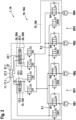
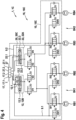
- the illustrated exemplary embodiments of a multi-circuit hydraulically open brake system 1, 1A, 1B, 1C, 1D according to the invention without mechanical and/or hydraulic intervention via the driver, in particular for a highly automated or autonomous vehicle each comprise at least two wheel brakes RB1, RB2, RB3 , RB4, which are each assigned to a brake circuit BK1, BK2 with a pressure relief path 9.1, 9.2, two pressure generators 12, 22, which are hydraulically connected in parallel between at least one fluid container 17, 27 and the at least two wheel brakes RB1, RB2, RB3, RB4, and a modulation unit 16, 16A, 16B, 16C, 16D for hydraulically connecting the pressure generators 12, 22 to the at least two wheel brakes RB1, RB2, RB3, RB4 and for individual brake pressure modulation in the at least two wheel brakes RB1, RB2, RB3, RB4.
- a first pressure generator 12 is assigned to a main system 10, 10A, 10B, 10C, 10D, which includes a first energy supply EV1 and a first evaluation and control unit 14, and via a first shut-off valve V1 with at least one wheel brake RB1, RB2 of a first brake circuit BK1 and can be connected via a second shut-off valve V2 to at least one wheel brake RB3, RB4 of a second brake circuit BK2.
- a second pressure generator 22 is assigned to a secondary system 20, 20A, 20B, 20C, 20D, which includes a second energy supply EV2 that is independent of the first energy supply EV1 and a second evaluation and control unit 24, and via a third shut-off valve V3 with at least one wheel brake RB1 , RB2 of the first brake circuit BK1 and a fourth check valve V4 with at least one wheel brake RB3, RB4 of the second brake circuit BK2 can be connected.
- the second evaluation and control unit 24 controls the second pressure generator 22, with components of the modulation unit 16, 16A, 16B, 16C, 16D being assigned to the main system 10, 10A, 10B, 10C, 10D for individual brake pressure modulation, so that these components of the modulation unit 16, 16A, 16B, 16C, 16D and the first pressure generator 12 are controlled by the first evaluation and control unit 14 and supplied with energy by the first energy supply EV1.
- shut-off valves V1, V2, V3, V4 can be controlled by the first evaluation and control unit 14 and/or by the second evaluation and control unit 24 in such a way that when one of the two pressure generators 12, 22 is activated, a hydraulic fluid does not flow through the other of the two pressure generators 12, 22 is passed.
- the brake systems 1, 1A, 1B, 1C, 1D shown each include two brake circuits BK1, BK2, each with a pressure relief path 9.1, 9.2 and four wheel brakes RB1, RB2, RB3, RB4, with a first wheel brake RB1 and a second wheel brake RB2 and a first pressure relief path 9.1 are assigned to a first brake circuit BK1 and a third wheel brake RB3 and a fourth wheel brake RB4 and a second pressure relief path 9.2 to a second brake circuit.
- an X distribution of the wheel brakes RB1, RB2, RB3, RB4 to the two brake circuits BK1, BK2 is possible, ie the first wheel brake RB1 is on the left front wheel and the second wheel brake RB2 is on the right rear wheel and the third wheel brake RB2 is on the right Front wheel and the fourth wheel brake RB4 is arranged on the left rear wheel.
- a II distribution of the wheel brakes RB1, RB2, RB3, RB4 to the two brake circuits BK1, BK2 is possible, ie the first wheel brake RB1 is on the left front wheel and the second wheel brake RB2 is on the right front wheel and the third wheel brake RB3 is on left rear wheel and the fourth wheel brake RB4 is arranged on the right rear wheel.
- a first fluid container 17 with at least one fluid chamber 17.1, 17.2 is assigned to the main system 10, 10A, 10B, 10C, 10D
- a second fluid container 27 with at least one fluid chamber 27.1, 27.2 is assigned to the secondary system 20, 20A, 20B, 20C, 20D assigned.
- the two fluid containers 17, 27 can be combined to form a common fluid container 7.
- first pressure generator 12 is designed as a plunger system 12A, 12B in the illustrated exemplary embodiments of the brake system 1, 1A, 1B, 1C, 1D.
- the second pressure generator 22 is also designed as a plunger system 22A, 22B in the illustrated exemplary embodiments of the brake system 1, 1A, 1B, 1C, 1D.
- both pressure generators 12, 22 or at least one of the two pressure generators 12, 22 can be designed as a pump system.
- the modulation unit 16, 16A, 16B, 16C, 16D in the illustrated exemplary embodiments of the brake system 1, 1A, 1B, 1C, 1D includes an inlet valve IV1, IV2, IV3 for each wheel brake RB1, RB2, RB3, RB4, IV4, which are designed as controllable normally open solenoid valves, and one outlet valve OV1, OV2, OV3, OV4, which are designed as electromagnetic normally closed switching valves.
- the outlet valves OV1, OV2, OV3, OV4 can be designed as controllable normally closed solenoid valves.
- a first inlet valve IV1 and a first outlet valve OV1 are assigned to the first wheel brake RB1.
- a second inlet valve IV2 and a second outlet valve OV2 are assigned to the second wheel brake RB2.
- a third inlet valve IV3 and a third outlet valve OV3 are assigned to the third wheel brake RB3, and a fourth inlet valve IV4 and a fourth outlet valve OV4 are assigned to the fourth wheel brake RB4.
- the brake fluid or hydraulic fluid from the wheel brakes RB1, RB2, RB3, RB4 is returned to the first fluid tank 17, which is assigned to the main system 10, 10A, 10B, 10C, 10D.
- first pressure generator 12, the second pressure generator 22 and the modulation unit 16 are in the illustrated Embodiments arranged in a common hydraulic block, in which the corresponding hydraulic connecting lines or connecting channels are formed.
- the shut-off valves V1, V2, V3, V4 are also arranged in this common hydraulic block.
- the first pressure generator 12 and the modulation unit 16 are arranged in a first hydraulic block
- the second pressure generator 22 is arranged in a second hydraulic block.
- the first fluid container 17 is connected to the first hydraulic block or integrated into the first hydraulic block
- the second fluid container 27 is connected to the second hydraulic block or integrated into the second hydraulic block.
- the first pressure generator 12 in the illustrated first exemplary embodiment of the brake system 1A is designed as a single circuit and includes a plunger system 12A with a piston-cylinder unit, which has a piston and a chamber 12.1, and a drive 12.3.
- the drive 12.3 is designed as an electric motor and moves the piston against the force of a return spring to set the pressure in the chamber 12.1.
- the second pressure generator 22 has two circuits and includes a plunger system 22A with a piston-cylinder unit, which has two pistons and two chambers 22.1, 22.2, and a drive 22.3.
- the drive 22.3 is designed as an electric motor and moves the two pistons against the force of the corresponding return springs to set the pressure in the chambers 22.1, 22.2.
- the first fluid container 17 comprises only one fluid chamber 17.1, which is hydraulically connected to the chamber 12.1 of the first plunger system 12A and the pressure relief paths 9.1, 9.2.
- the chamber 12.1 of the first plunger system 12A is assigned to the first brake circuit BK1 and the second brake circuit BK2.
- a suction line with a check valve is provided for the first pressure generator 12, which also hydraulically connects the chamber 12.1 of the first plunger system 12A to the first fluid container 17.
- the second fluid container 27 comprises two fluid chambers 27.1, 27.2, with a first fluid chamber 27.1 hydraulically connected to a first chamber 22.1 of the second plunger system 22A and a second fluid chamber 27.2 hydraulically connected to a second chamber 22.2 of the second plunger system 22A connected is.
- the first chamber 22.1 is assigned to the second brake circuit BK2
- the second chamber 22.2A is assigned to the first brake circuit BK1.
- the piston-cylinder units of the first and second plunger systems 12A, 22A are designed so that they can flow through them in the de-energized state, so that brake fluid can flow through the corresponding chambers 12.1, 22.1, 22.2.
- the first shutoff valve V1 and the second shutoff valve V2 in the exemplary embodiment shown are each designed as normally closed solenoid valves, and the third shutoff valve V3 and the fourth shutoff valve V4 are designed as normally open solenoid valves, with the first evaluation and control unit 14 Shut-off valves V1, V2, V3, V4 drives.
- the shut-off valves V1, V2, V3, V4 belong to the main system 10A and are powered by the first power supply unit EV1.
- the first pressure generator 12 is hydraulically separated from the wheel brakes RB1, RB2, RB3, RB4 due to the normally closed design of the first shut-off valve V1 and the second shut-off valve V1.
- the second pressure generator 22 is hydraulically connected to the wheel brakes RB1, RB2, RB3, RB4 due to the normally open design of the third shut-off valve V3 and the fourth shut-off valve V4. Therefore, in normal operation, in which the first pressure generator 12 generates the pressure for the wheel brakes RB1, RB2, RB3, RB4, it is necessary to activate the shut-off valves V1, V2, V3, V4 in order to hydraulically connect the first pressure generator 12 to the wheel brakes RB1, RB2 , RB3, RB4 to connect and to separate the second pressure generator 22 hydraulically from the wheel brakes RB1, RB2, RB3, RB4.
- wheel brakes RB1, RB2, RB3, RB4 are connected to the second fluid container 27 via the second pressure generator 22 in order to be able to compensate for a temperature-related expansion of the brake fluid by so-called “breathing” in the currentless or passive state. Therefore, in this context one speaks of "breathing through the secondary system 20A".
- the first pressure generator 12 in the illustrated second exemplary embodiment of the brake system 1B has two circuits and includes a plunger system 12B with a piston-cylinder unit, which has two pistons and two chambers 12.1, 12.2, and a drive 12.3.
- the drive 12.3 is designed as an electric motor and moves the two pistons in opposite directions the force of corresponding return springs for setting the pressure in the chambers 12.1, 12.2.
- the second pressure generator 22 is designed as a single circuit and includes a plunger system 22B with a piston-cylinder unit, which has a piston and a chamber 22.1, and a drive 22.3.
- the drive 22.3 is designed as an electric motor and moves the piston against the force of a return spring to set the pressure in the chamber 12.1.
- the first fluid container 17 comprises two fluid chambers 17.1, 17.2, a first fluid chamber 17.1 being hydraulically connected to a first chamber 12.1 of the first plunger system 12B and a first pressure relief path 9.1.
- a second fluid chamber 17.2 is hydraulically connected to a second chamber 12.2 of the first plunger system 12B and a second pressure relief path 9.2.
- the first chamber 12.1 is assigned to the first brake circuit BK1 and the second chamber 12.2 is assigned to the second brake circuit BK2.
- two suction lines with a check valve are provided for the first pressure generator 12, which also hydraulically connect the chambers 12.1, 12.2 of the first plunger system 12B to the first fluid container 17.
- the second fluid container 27 comprises only one fluid chamber 27.1, which is hydraulically connected to the chamber 22.1 of the second plunger system 22B.
- the chamber 22.1 of the second plunger system 22B is assigned to the first brake circuit BK1 and the second brake circuit BK2.
- the piston-cylinder units of the first and second plunger systems 12B, 22B are designed so that they can flow through them in the de-energized state, so that brake fluid can flow through the corresponding chambers 12.1, 12.2, 22.1.
- the first shutoff valve V1 and the second shutoff valve V2 in the exemplary embodiment shown are each designed as normally open solenoid valves, and the third shutoff valve V3 and the fourth shutoff valve V4 are designed as normally closed solenoid valves, with the second evaluation and control unit 14 Shut-off valves V1, V2, V3, V4 drives.
- the shutoff valves V1, V2, V3, V4 belong to the secondary system 20B and are powered by the second power supply unit EV2. Due to the normally open design of the first shut-off valve V1 and the second shut-off valve V1, the first pressure generator 12 is hydraulic with the wheel brakes RB1, RB2, RB3, RB4 tied together.
- the second pressure generator 22 is hydraulically separated from the wheel brakes RB1, RB2, RB3, RB4 because the third shut-off valve V3 and the fourth shut-off valve V4 are closed when de-energized. Therefore, in normal operation, in which the first pressure generator 12 generates the pressure for the wheel brakes RB1, RB2, RB3, RB4, it is not necessary to activate the shut-off valves V1, V2, V3, V4 in order to hydraulically connect the first pressure generator 12 to the wheel brakes RB1, To connect RB2, RB3, RB4 and to separate the second pressure generator 22 hydraulically from the wheel brakes RB1, RB2, RB3, RB4.
- wheel brakes RB1, RB2, RB3, RB4 are connected to the first fluid container 17 via the first pressure generator 22 in order to be able to compensate for a temperature-related expansion of the brake fluid by so-called “breathing” in the currentless or passive state. Therefore, in this context one speaks of "breathing through the main system 10B".
- the first pressure generator 12 in the illustrated third exemplary embodiment of the brake system 1C has two circuits and includes a plunger system 12B with a piston-cylinder unit which has two pistons and two chambers 12.1, 12.2, and a drive 12.3.
- the drive 12.3 is designed as an electric motor and moves the two pistons against the force of the corresponding return springs to set the pressure in the chambers 12.1, 12.2.
- the second pressure generator 22 has two circuits and includes a plunger system 22A with a piston-cylinder unit, which has two pistons and two chambers 22.1, 22.2, and a drive 22.3.
- the drive 22.3 is designed as an electric motor and moves the two pistons against the force of the corresponding return springs to set the pressure in the chambers 22.1, 22.2.
- the first fluid container 17 comprises two fluid chambers 17.1, 17.2, a first fluid chamber 17.1 being hydraulically connected to a first chamber 12.1 of the first plunger system 12B and a first pressure relief path 9.1.
- a second fluid chamber 17.2 is hydraulically connected to a second chamber 12.2 of the first plunger system 12B and a second pressure relief path 9.2.
- the first chamber 12.1 is assigned to the first brake circuit BK1 and the second chamber 12.2 is assigned to the second brake circuit BK2.
- two suction lines are included for the first pressure generator 12 Check valve provided which connect the chambers 12.1, 12.2 of the first plunger system 12B in addition to the first fluid container 17 hydraulically.
- the second fluid container 27 comprises two fluid chambers 27.1, 27.2, a first fluid chamber 27.1 being hydraulically connected to a first chamber 22.1 of the second plunger system 22A and a second fluid chamber 27.2 being hydraulically connected to a second chamber 22.2 of the second plunger system 22A.
- first chamber 22.1 is assigned to the second brake circuit BK2
- second chamber 22.2 is assigned to the first brake circuit BK1.
- the piston-cylinder units of the first and second plunger systems 12A, 22A are designed so that they can flow through them in the currentless state, so that brake fluid can flow through the corresponding chambers 12.1, 12.2, 22.1, 22.2.
- the first shutoff valve V1 and the second shutoff valve V2 in the exemplary embodiment shown are each designed as normally closed solenoid valves, and the third shutoff valve V3 and the fourth shutoff valve V4 are designed as normally open solenoid valves, with the first evaluation and control unit 14 Shut-off valves V1, V2, V3, V4 drives.
- the shutoff valves V1, V2, V3, V4 belong to the main system 10C and are powered by the first power supply unit EV1.
- the first pressure generator 12 is hydraulically separated from the wheel brakes RB1, RB2, RB3, RB4 due to the normally closed design of the first shut-off valve V1 and the second shut-off valve V1.
- the second pressure generator 22 is hydraulically connected to the wheel brakes RB1, RB2, RB3, RB4 due to the normally open design of the third shut-off valve V3 and the fourth shut-off valve V4. Therefore, in normal operation, in which the first pressure generator 12 generates the pressure for the wheel brakes RB1, RB2, RB3, RB4, it is necessary to activate the shut-off valves V1, V2, V3, V4 in order to hydraulically connect the first pressure generator 12 to the wheel brakes RB1, RB2 , RB3, RB4 to connect and to separate the second pressure generator 22 hydraulically from the wheel brakes RB1, RB2, RB3, RB4.
- wheel brakes RB1, RB2, RB3, RB4 are connected to the second fluid container 27 via the second pressure generator 22 in order to be able to compensate for a temperature-related expansion of the brake fluid by so-called “breathing” in the currentless or passive state. Therefore, one speaks of "breathing through the secondary system 20C" in this context.
- the first pressure generator 12 in the illustrated fourth exemplary embodiment of the braking system 1D has two circuits and includes a plunger system 12B with a piston-cylinder unit, which has two pistons and two chambers 12.1, 12.2, and a drive 12.3.
- the drive 12.3 is designed as an electric motor and moves the two pistons against the force of the corresponding return springs to set the pressure in the chambers 12.1, 12.2.
- the second pressure generator 22 has two circuits and includes a plunger system 22A with a piston-cylinder unit, which has two pistons and two chambers 22.1, 22.2, and a drive 22.3.
- the drive 22.3 is designed as an electric motor and moves the two pistons against the force of the corresponding return springs to set the pressure in the chambers 22.1, 22.2.
- the first fluid container 17 comprises two fluid chambers 17.1, 17.2, a first fluid chamber 17.1 being hydraulically connected to a first chamber 12.1 of the first plunger system 12B and a first pressure relief path 9.1.
- a second fluid chamber 17.2 is hydraulically connected to a second chamber 12.2 of the first plunger system 12B and a second pressure relief path 9.2.
- the first chamber 12.1 is assigned to the first brake circuit BK1 and the second chamber 12.2 is assigned to the second brake circuit BK2.
- the modulation unit 16C for the first pressure generator 12 includes two suction lines with a check valve, which also hydraulically connect the chambers 12.1, 12.2 of the first plunger system 12B to the first fluid container 17.
- the second fluid container 27 comprises two fluid chambers 27.1, 27.2, a first fluid chamber 27.1 being hydraulically connected to a first chamber 22.1 of the second plunger system 22A and a second fluid chamber 27.2 being hydraulically connected to a second chamber 22.2 of the second plunger system 22A.
- first chamber 22.1 is assigned to the second brake circuit BK2
- second chamber 22.2 is assigned to the first brake circuit BK1.
- the piston-cylinder units of the first and second plunger systems 12A, 22A are designed so that they can flow through them in the currentless state, so that brake fluid can flow through the corresponding chambers 12.1, 12.2, 22.1, 22.2.
- the first shutoff valve V1 and the second shutoff valve V2 in the exemplary embodiment shown are each designed as normally open solenoid valves, and the third shutoff valve V3 and the fourth shutoff valve V4 are designed as normally closed solenoid valves, with the second evaluation and control unit 14 Shut-off valves V1, V2, V3, V4 drives.
- the shut-off valves V1, V2, V3, V4 belong to the secondary system 20D and are powered by the second power supply unit EV2. Due to the normally open design of the first shut-off valve V1 and the second shut-off valve V1, the first pressure generator 12 is hydraulically connected to the wheel brakes RB1, RB2, RB3, RB4.
- the second pressure generator 22 is hydraulically separated from the wheel brakes RB1, RB2, RB3, RB4 because the third shut-off valve V3 and the fourth shut-off valve V4 are closed when de-energized. Therefore, in normal operation, in which the first pressure generator 12 generates the pressure for the wheel brakes RB1, RB2, RB3, RB4, it is not necessary to activate the shut-off valves V1, V2, V3, V4 in order to hydraulically connect the first pressure generator 12 to the wheel brakes RB1, To connect RB2, RB3, RB4 and to separate the second pressure generator 22 hydraulically from the wheel brakes RB1, RB2, RB3, RB4.
- wheel brakes RB1, RB2, RB3, RB4 are connected to the first fluid container 17 via the first pressure generator 22 in order to be able to compensate for a temperature-related expansion of the brake fluid by so-called “breathing” in the currentless or passive state. Therefore, in this context one speaks of "breathing through the main system 10D".
- the main system 10 increases or reduces or stops in normal operation , 10A, 10B, 10C, 10D by means of the first pressure generator 12 the pressure in the brake circuits BK1, BK2 and by means of the modulation unit 16, 16A, 16B, 16C, 16D the individual brake pressure modulation in the at least two wheel brakes RB1, RB2, RB3, RB4 out of.
- the secondary system 20, 20A, 20B, 20C, 20D increases or decreases or holds by means of the second pressure generator 22 the pressure in the brake circuits BK1, BK2 and the individual brake pressure modulation in the at least two wheel brakes RB1, RB2, RB3, RB4 are omitted.
- first shutoff valve V1 and the second shutoff valve V2 are placed in the open state, and the third shutoff valve V3 and the fourth shutoff valve V4 are placed in the closed state.
- the drive 12.3 of the first pressure generator 12 is actuated accordingly.
- the associated inlet valve IV1, IV2, IV3, IV4 is opened and the associated outlet valve OV1, OV2, OV3, OV4 is closed for the individual pressure increase in an associated wheel brake RB1, RB2, RB3, RB4.
- the associated inlet valve IV1, IV2, IV3, IV4 and the associated outlet valve OV1, OV2, OV3, OV4 are closed for individual pressure maintenance in an associated wheel brake RB1, RB2, RB3, RB4.
- the associated inlet valve IV1, IV2, IV3, IV4 is closed and the associated outlet valve OV1, OV2, OV3, OV4 is opened.
- the associated shut-off valve V1, V2 is closed when a leak is detected in a brake circuit BK1, BK2. If a leak is detected in one of the wheel brakes RB1, RB2, RB3, RB4, the associated inlet valve IV1, IV2, IV3, IV4 is closed.
- This method can be implemented, for example, in software or hardware or in a mixed form of software and hardware, for example in a control unit.
- Embodiments of the present invention provide a multi-circuit, hydraulically open brake system without mechanical and/or hydraulic intervention by the driver, in particular for a highly automated or autonomous vehicle, and a corresponding operating method, with the pressure generators used, which are hydraulically connected in parallel, being controlled by the hydraulic circuit via the modulation unit act on all wheel brakes of the vehicle.
Landscapes
- Engineering & Computer Science (AREA)
- Transportation (AREA)
- Mechanical Engineering (AREA)
- Regulating Braking Force (AREA)
Claims (18)
- Système de freinage (1) hydrauliquement ouvert, à plusieurs circuits, sans intervention mécanique et/ou hydraulique par le conducteur, en particulier pour un véhicule hautement automatisé ou autonome, comprenant au moins deux freins de roue (RB1, RB2, RB3, RB4) qui sont respectivement associés à un circuit de freinage (BK1, BK2) pourvu d'un chemin de relâchement de pression (9.1, 9.2), deux générateurs de pression (12, 22) qui sont montés hydrauliquement en parallèle entre au moins un réservoir de fluide (17, 27) et les au moins deux freins de roue (RB1, RB2, RB3, RB4), et une unité de modulation (16) pour la connexion hydraulique des générateurs de pression (12, 22) auxdits au moins deux freins de roue (RB1, RB2, RB3, RB4) et pour la modulation individuelle de la pression de freinage dans les au moins deux freins de roue (RB1, RB2, RB3, RB4), dans lequel un premier (12) des deux générateurs de pression (12, 22) est associé à un système principal (10) qui comprend une première alimentation en énergie (EV1) et une première unité d'évaluation et de commande (14), dans lequel un deuxième (22) des deux générateurs de pression (12, 22) est associé à un système secondaire (20) qui comprend une deuxième alimentation en énergie (EV2) indépendante de la première alimentation en énergie (EV1) et une deuxième unité d'évaluation et de commande (24), la deuxième unité d'évaluation et de commande (24) pilotant le deuxième générateur de pression (22), dans lequel des composants de l'unité de modulation (16) sont associés au système principal (10) pour la modulation individuelle de la pression de freinage de sorte que ces composants de l'unité de modulation (16) et le premier générateur de pression (12) sont pilotés par la première unité d'évaluation et de commande (14) et sont alimentés en énergie par la première alimentation en énergie (EV1),
caractérisé en ce que le premier générateur de pression (12) des deux générateurs de pression (12, 22) peut être relié par une première soupape d'arrêt (V1) à au moins un frein de roue (RB1, RB2) du premier circuit de freinage (BK1) et peut être relié par une deuxième soupape d'arrêt (V2) à au moins un frein de roue (RB3, RB4) du deuxième circuit de freinage (BK2), dans lequel le deuxième générateur de pression (22) des deux générateurs de pression (12, 22) peut être relié par une troisième soupape d'arrêt (V3) à au moins un frein de roue (RB1, RB2) du premier circuit de freinage (BK1) et peut être relié par une quatrième soupape d'arrêt (V4) à au moins un frein de roue (RB3, RB4) du deuxième circuit de freinage (BK2), dans lequel les soupapes d'arrêt (V1, V2, V3, V4) peuvent être pilotées par la première unité d'évaluation et de commande (14) et/ou par la deuxième unité d'évaluation et de commande (24) de telle sorte que lors de l'activation d'un des deux générateurs de pression (12, 22) un fluide hydraulique ne soit pas conduit par l'autre des deux générateurs de pression (12, 22). - Système de freinage (1) selon la revendication 1, caractérisé en ce que le premier générateur de pression (12) est réalisé avec un circuit ou avec deux circuits.
- Système de freinage (1) selon la revendication 1 ou 2, caractérisé en ce que le deuxième générateur de pression (22) est réalisé avec un circuit ou avec deux circuits.
- Système de freinage (1) selon l'une quelconque des revendications 1 à 3, caractérisé en ce que la première soupape d'arrêt (V1) et la deuxième soupape d'arrêt (V2) sont respectivement réalisées sous forme d'électrovannes fermées hors tension, et la troisième soupape d'arrêt (V3) et la quatrième soupape d'arrêt (V4) sans réalisées sous forme d'électrovannes ouvertes hors tension, la première unité d'évaluation et de commande (14) pilotant les soupapes d'arrêt (V1, V2, V3, V4).
- Système de freinage (1) selon l'une quelconque des revendications 1 à 3, caractérisé en ce que la première soupape d'arrêt (V1) et la deuxième soupape d'arrêt (V2) sont respectivement réalisées sous forme d'électrovannes ouvertes hors tension, et la troisième soupape d'arrêt (V3) et la quatrième soupape d'arrêt (V4) sont réalisées sous forme d'électrovannes fermées hors tension, la deuxième unité d'évaluation et de commande (24) pilotant les soupapes d'arrêt (V1, V2, V3, V4).
- Système de freinage (1) selon l'une quelconque des revendications 1 à 5, caractérisé en ce que le système principal (10) et le système secondaire (20) présentent un réservoir de fluide commun (7), ou un premier réservoir de fluide (17) pourvu d'au moins une chambre de fluide (17.1, 17.2) est associé au système principal (10), et un deuxième réservoir de fluide (27) pourvu d'au moins une chambre de fluide (27.1, 27.2) est associé au système secondaire (20).
- Système de freinage (1) selon l'une quelconque des revendications 1 à 6, caractérisé en ce que le premier générateur de pression (12) est réalisé sous forme de système à piston plongeur (12A) ou de système à pompe.
- Système de freinage (1) selon la revendication 7, caractérisé en ce que pour le premier générateur de pression (12), au moins une conduite d'aspiration à clapet antiretour est prévue qui relie hydrauliquement le premier générateur de pression (12) en plus au premier réservoir de fluide (17).
- Système de freinage (1) selon l'une quelconque des revendications 1 à 8, caractérisé en ce que le deuxième générateur de pression (22) est réalisé sous forme de système à piston plongeur (22A) ou de système à pompe.
- Système de freinage (1) selon l'une quelconque des revendications 7 à 9, caractérisé en ce que le système à piston plongeur (12A, 22A) présente une unité piston/cylindre pourvue d'au moins un piston et d'au moins une chambre (12.1, 12.2, 22.1, 22.2) et d'un entraînement (12.3, 22.3), dans lequel l'entraînement (12.3, 22.3) déplace ledit au moins un piston contre la force d'un ressort de rappel pour régler la pression dans ladite au moins une chambre (12.1, 12.2, 22.1, 22.2) .
- Système de freinage (1) selon l'une quelconque des revendications 7 à 10, caractérisé en ce que le système à pompe présente au moins une pompe et au moins un entraînement qui entraîne ladite au moins une pompe.
- Système de freinage (1) selon l'une quelconque des revendications 6 à 11, caractérisé en ce que pendant une modulation individuelle de la pression de freinage dans ledit au moins un frein de roue (RB1, RB2, RB3, RB4) un fluide de freinage évacué du au moins un frein de roue (RB1, RB2, RB3, RB4) est recyclé par ledit au moins un chemin de relâchement de pression (9.1, 9.2) soit dans le premier réservoir de fluide (17), soit dans le deuxième réservoir de fluide (27).
- Système de freinage (1) selon l'une quelconque des revendications 1 à 12, caractérisé en ce que le premier générateur de pression (12), le deuxième générateur de pression (22) et l'unité de modulation (16) sont disposés dans un bloc hydraulique commun.
- Système de freinage (1) selon l'une quelconque des revendications 1 à 12, caractérisé en ce que le premier générateur de pression (12) et l'unité de modulation (16) sont disposés dans un premier bloc hydraulique, et le deuxième générateur de pression (22) est disposé dans un deuxième bloc hydraulique.
- Procédé de fonctionnement pour un système de freinage (1) hydrauliquement ouvert, à plusieurs circuits, sans intervention mécanique et/ou hydraulique par le conducteur, en particulier pour un véhicule hautement automatisé ou autonome, qui est réalisé selon au moins l'une des revendications 1 à 14, dans lequel, en fonctionnement normal, le système principal (10) augmente ou réduit ou maintient la pression dans les circuits de freinage (BK1, BK2) au moyen du premier générateur de pression (12) des deux générateurs de pression (12, 22), et réalise au moyen de l'unité de modulation (16) la modulation individuelle de la pression de freinage dans les au moins deux freins de roue (RB1, RB2, RB3, RB4), dans lequel, en cas de défaillance du système principal (10), le système secondaire (20) augmente ou réduit ou maintient la pression dans les circuits de freinage (BK1, BK2) au moyen du deuxième générateur de pression (22) des deux générateurs de pression (12, 22), et la modulation individuelle de la pression de freinage est omise dans les au moins deux freins de roue (RB1, RB2, RB3, RB4).
- Procédé de fonctionnement selon la revendication 16, caractérisé en ce qu'en fonctionnement normal, la première soupape d'arrêt (V1) et la deuxième soupape d'arrêt (V2) passent à l'état ouvert, et la troisième soupape d'arrêt (V3) et la quatrième soupape d'arrêt (V4) passent à l'état fermé, dans lequel pour l'augmentation de la pression ou pour la réduction de la pression ou pour le maintien de la pression dans les circuits de freinage (BK1, BK2), l'entraînement (12.3) du premier générateur de pression (12) est piloté de façon adéquate.
- Procédé de fonctionnement selon la revendication 16 ou 17, caractérisé en ce qu'en fonctionnement normal, pour l'augmentation individuelle de la pression dans un frein de roue (RB1, RB2, RB3, RB4) associé, la soupape d'entrée (IV1, IV2, IV3, IV4) associée s'ouvre et la soupape de sortie (OV1, OV2, OV3, OV4) associée se ferme, dans lequel pour le maintien individuel de la pression dans un frein de roue (RB1, RB2, RB3, RB4) associé, la soupape d'entrée (IV1, IV2, IV3, IV4) associée et la soupape de sortie (OV1, OV2, OV3, OV4) associée se ferment, et dans lequel, pour la réduction individuelle de la pression dans un frein de roue (RB1, RB2, RB3, RB4) associé, la soupape d'entrée (IV1, IV2, IV3, IV4) associée se ferme et la soupape de sortie (OV1, OV2, OV3, OV4) associée s'ouvre.
- Procédé de fonctionnement selon l'une quelconque des revendications 16 à 18, caractérisé en ce qu'en cas de défaillance du système principal (10), la première soupape d'arrêt (V1) et la deuxième soupape d'arrêt (V2) passent à l'état fermé et la troisième soupape d'arrêt (V3) et la quatrième soupape d'arrêt (V4) passent à l'état ouvert, dans lequel pour l'augmentation de la pression ou pour la réduction de la pression ou pour le maintien de la pression dans les circuits de freinage (BK1, BK2), l'entraînement (22.3) du deuxième générateur de pression (22) est piloté de façon adéquate.
Applications Claiming Priority (2)
| Application Number | Priority Date | Filing Date | Title |
|---|---|---|---|
| DE102018206082.7A DE102018206082A1 (de) | 2018-04-20 | 2018-04-20 | Mehrkreisiges hydraulisch offenes Bremssystem, insbesondere für ein hochautomatisiertes oder autonomes Fahrzeug |
| PCT/EP2019/058586 WO2019201619A1 (fr) | 2018-04-20 | 2019-04-05 | Système de freinage hydrauliquement ouvert à plusieurs circuits, notamment pour véhicule autonome ou fortement automatisé |
Publications (2)
| Publication Number | Publication Date |
|---|---|
| EP3781445A1 EP3781445A1 (fr) | 2021-02-24 |
| EP3781445B1 true EP3781445B1 (fr) | 2023-06-07 |
Family
ID=66240060
Family Applications (1)
| Application Number | Title | Priority Date | Filing Date |
|---|---|---|---|
| EP19718593.7A Active EP3781445B1 (fr) | 2018-04-20 | 2019-04-05 | Système de freinage hydrauliquement ouvert à plusieurs circuits, notamment pour véhicule autonome ou fortement automatisé |
Country Status (5)
| Country | Link |
|---|---|
| US (1) | US11981304B2 (fr) |
| EP (1) | EP3781445B1 (fr) |
| CN (1) | CN112055673B (fr) |
| DE (1) | DE102018206082A1 (fr) |
| WO (1) | WO2019201619A1 (fr) |
Families Citing this family (6)
| Publication number | Priority date | Publication date | Assignee | Title |
|---|---|---|---|---|
| US11535227B2 (en) * | 2017-12-31 | 2022-12-27 | ZF Active Safety US Inc. | Vehicle brake system and self-diagnostic testing |
| DE102018202887A1 (de) * | 2018-02-26 | 2019-08-29 | Robert Bosch Gmbh | Mehrkreisiges hydraulisch geschlossenes Bremssystem, insbesondere für ein hochautomatisiertes oder autonomes Fahrzeug |
| DE102018206079A1 (de) * | 2018-04-20 | 2019-10-24 | Robert Bosch Gmbh | Mehrkreisiges hydraulisch offenes Bremssystem, insbesondere für ein hochautomatisiertes oder autonomes Fahrzeug |
| AU2019272061B2 (en) * | 2019-11-29 | 2025-11-27 | Caterpillar Inc. | Braking system for machine |
| DE102020102590B4 (de) * | 2020-01-28 | 2025-01-09 | Ipgate Ag | Bremssystem sowie Verfahren zum Steuern eines Bremssystems |
| JP7409252B2 (ja) * | 2020-07-31 | 2024-01-09 | 株式会社アドヴィックス | 車両用制動装置 |
Family Cites Families (18)
| Publication number | Priority date | Publication date | Assignee | Title |
|---|---|---|---|---|
| DE102008041760A1 (de) | 2008-06-11 | 2009-12-17 | Robert Bosch Gmbh | Bremseinrichtung für ein Kraftfahrzeug |
| DE102009001135A1 (de) | 2009-02-25 | 2010-08-26 | Robert Bosch Gmbh | Verfahren zur Betätigung einer hydraulischen Fahrzeugbremsanlage |
| DE102010040097A1 (de) * | 2009-09-11 | 2011-03-31 | Continental Teves Ag & Co. Ohg | Bremsanlage für Kraftfahrzeuge |
| DE102010023865B4 (de) * | 2010-06-15 | 2024-03-28 | Zf Active Safety Gmbh | Hydraulikdruckerzeuger für eine Fahrzeug-Bremsanlage |
| DE102012205862A1 (de) * | 2011-04-19 | 2012-10-25 | Continental Teves Ag & Co. Ohg | Bremsanlage für Kraftfahrzeuge sowie Verfahren zum Betrieb einer Bremsanlage |
| DE102012205962A1 (de) * | 2011-05-05 | 2012-11-08 | Continental Teves Ag & Co. Ohg | Bremsanlage für Kraftfahrzeuge sowie Verfahren zum Betrieb einer Bremsanlage |
| DE102013206324A1 (de) | 2013-04-10 | 2014-10-16 | Robert Bosch Gmbh | Bremssystem für ein Fahrzeug und Verfahren zum Betreiben des Bremssystems |
| DE102013223861A1 (de) * | 2013-11-21 | 2015-05-21 | Continental Teves Ag & Co. Ohg | Bremsanlage für Kraftahrzeuge |
| US9296370B2 (en) * | 2013-12-04 | 2016-03-29 | Continental Automotive Systems, Inc. | Hydraulic and electronic braking system for autonomous braking |
| DE102013227065B4 (de) | 2013-12-23 | 2016-02-18 | Robert Bosch Gmbh | Hydraulisches Bremssystem mit erstem und zweitem Bremsdruckerzeuger sowie Verfahren zum Betreiben eines Bremssystems |
| DE102015206572A1 (de) | 2014-05-15 | 2015-11-19 | Continental Teves Ag & Co. Ohg | Bremsanlage für Kraftfahrzeuge |
| US10166964B2 (en) | 2014-07-10 | 2019-01-01 | Continental Automotive Systems, Inc. | Pedalless electronically controlled hydraulic braking system with redundant pump |
| WO2016146222A2 (fr) * | 2015-03-16 | 2016-09-22 | Ipgate Ag | Système de freinage équipé d'une unité à maître-cylindre de frein à régulation mux innovante (mux 2.0) comprenant au moins une soupape de sortie, et procédé servant à la régulation de pression |
| DE102015204866A1 (de) | 2015-03-18 | 2016-09-22 | Robert Bosch Gmbh | Verfahren zum Betreiben eines rekuperativen Bremssystems eines Fahrzeugs und Steuervorrichtung für ein rekuperatives Bremssystem eines Fahrzeugs |
| DE102016105232A1 (de) * | 2016-03-21 | 2017-09-21 | Ipgate Ag | Betätigungsvorrichtung für ein hydraulisches Betätigungssystem, insbesondere eine Kraftfahrzeugbremse oder einen elektrifizierten Kupplungs- und Gangsteller |
| DE102016211982A1 (de) | 2016-06-30 | 2018-01-04 | Robert Bosch Gmbh | Bremsvorrichtung für ein Fahrzeug |
| DE102018202885A1 (de) * | 2018-02-26 | 2019-08-29 | Robert Bosch Gmbh | Mehrkreisiges hydraulisch offenes Bremssystem, insbesondere für ein hochautomatisiertes oder autonomes Fahrzeug |
| DE102018206079A1 (de) * | 2018-04-20 | 2019-10-24 | Robert Bosch Gmbh | Mehrkreisiges hydraulisch offenes Bremssystem, insbesondere für ein hochautomatisiertes oder autonomes Fahrzeug |
-
2018
- 2018-04-20 DE DE102018206082.7A patent/DE102018206082A1/de active Pending
-
2019
- 2019-04-05 CN CN201980026588.9A patent/CN112055673B/zh active Active
- 2019-04-05 EP EP19718593.7A patent/EP3781445B1/fr active Active
- 2019-04-05 WO PCT/EP2019/058586 patent/WO2019201619A1/fr not_active Ceased
- 2019-04-05 US US17/046,239 patent/US11981304B2/en active Active
Also Published As
| Publication number | Publication date |
|---|---|
| DE102018206082A1 (de) | 2019-10-24 |
| CN112055673B (zh) | 2023-02-03 |
| US20210039616A1 (en) | 2021-02-11 |
| CN112055673A (zh) | 2020-12-08 |
| US11981304B2 (en) | 2024-05-14 |
| EP3781445A1 (fr) | 2021-02-24 |
| WO2019201619A1 (fr) | 2019-10-24 |
Similar Documents
| Publication | Publication Date | Title |
|---|---|---|
| EP3758989B1 (fr) | Système de freinage hydraulique ouvert à circuits multiples, notamment pour véhicule hautement automatisé ou autonome | |
| EP3781445B1 (fr) | Système de freinage hydrauliquement ouvert à plusieurs circuits, notamment pour véhicule autonome ou fortement automatisé | |
| DE102018206079A1 (de) | Mehrkreisiges hydraulisch offenes Bremssystem, insbesondere für ein hochautomatisiertes oder autonomes Fahrzeug | |
| EP3684659B1 (fr) | Système de freinage pour véhicule automobile et procédé de fonctionnement de celui-ci | |
| EP3568327B1 (fr) | Système de freinage pour véhicule automobile et deux procédés pour faire fonctionner ce système de freinage | |
| EP3160807B1 (fr) | Système de freinage pour véhicule à moteur | |
| EP3094528B1 (fr) | Système de freinage pour véhicules | |
| DE102014220440A1 (de) | Bremsensteuervorrichtung sowie Bremsanlage für Fahrzeuge | |
| DE102017222450A1 (de) | Bremsanlage für ein Kraftfahrzeug | |
| DE102010020002A1 (de) | Hydraulikbaugruppe für eine Fahrzeug-Bremsanlage | |
| DE102017222440A1 (de) | Bremsanlage für ein Kraftfahrzeug sowie Verfahren zu deren Betrieb | |
| DE102017222435A1 (de) | Bremsanlage für ein Kraftfahrzeug sowie Verfahren zu deren Betrieb | |
| EP3758988B1 (fr) | Système de freinage fermé hydraulique à plusieurs circuits | |
| EP3814180B1 (fr) | Système de frein hydraulique pour véhicule avec au moins deux essieux | |
| WO2019081414A1 (fr) | Système de freinage et deux procédés pour faire fonctionner un tel système de freinage | |
| DE102018208108A1 (de) | Mehrkreisiges hydraulisch offenes Bremssystem, insbesondere für ein hochautomatisiertes oder autonomes Fahrzeug | |
| EP3814181B1 (fr) | Système de frein hydraulique pour véhicule avec au moins deux essieux | |
| DE102018206716A1 (de) | Zweikreisiger Druckerzeuger für ein mehrkreisiges hydraulisches Bremssystem | |
| DE102019215288A1 (de) | Verfahren zur Steuerung einer elektronisch schlupfregelbaren Fremdkraftbremsanlage, insbesondere für ein Kraftfahrzeug und elektronisch schlupfregelbaren Fremdkraftbremsanlage, insbesondere für ein Kraftfahrzeug |
Legal Events
| Date | Code | Title | Description |
|---|---|---|---|
| STAA | Information on the status of an ep patent application or granted ep patent |
Free format text: STATUS: UNKNOWN |
|
| STAA | Information on the status of an ep patent application or granted ep patent |
Free format text: STATUS: THE INTERNATIONAL PUBLICATION HAS BEEN MADE |
|
| PUAI | Public reference made under article 153(3) epc to a published international application that has entered the european phase |
Free format text: ORIGINAL CODE: 0009012 |
|
| STAA | Information on the status of an ep patent application or granted ep patent |
Free format text: STATUS: REQUEST FOR EXAMINATION WAS MADE |
|
| 17P | Request for examination filed |
Effective date: 20201120 |
|
| AK | Designated contracting states |
Kind code of ref document: A1 Designated state(s): AL AT BE BG CH CY CZ DE DK EE ES FI FR GB GR HR HU IE IS IT LI LT LU LV MC MK MT NL NO PL PT RO RS SE SI SK SM TR |
|
| AX | Request for extension of the european patent |
Extension state: BA ME |
|
| DAV | Request for validation of the european patent (deleted) | ||
| DAX | Request for extension of the european patent (deleted) | ||
| STAA | Information on the status of an ep patent application or granted ep patent |
Free format text: STATUS: EXAMINATION IS IN PROGRESS |
|
| 17Q | First examination report despatched |
Effective date: 20220602 |
|
| GRAP | Despatch of communication of intention to grant a patent |
Free format text: ORIGINAL CODE: EPIDOSNIGR1 |
|
| STAA | Information on the status of an ep patent application or granted ep patent |
Free format text: STATUS: GRANT OF PATENT IS INTENDED |
|
| INTG | Intention to grant announced |
Effective date: 20230316 |
|
| GRAS | Grant fee paid |
Free format text: ORIGINAL CODE: EPIDOSNIGR3 |
|
| GRAA | (expected) grant |
Free format text: ORIGINAL CODE: 0009210 |
|
| STAA | Information on the status of an ep patent application or granted ep patent |
Free format text: STATUS: THE PATENT HAS BEEN GRANTED |
|
| AK | Designated contracting states |
Kind code of ref document: B1 Designated state(s): AL AT BE BG CH CY CZ DE DK EE ES FI FR GB GR HR HU IE IS IT LI LT LU LV MC MK MT NL NO PL PT RO RS SE SI SK SM TR |
|
| REG | Reference to a national code |
Ref country code: GB Ref legal event code: FG4D Free format text: NOT ENGLISH |
|
| REG | Reference to a national code |
Ref country code: CH Ref legal event code: EP Ref country code: AT Ref legal event code: REF Ref document number: 1574100 Country of ref document: AT Kind code of ref document: T Effective date: 20230615 Ref country code: DE Ref legal event code: R096 Ref document number: 502019008033 Country of ref document: DE |
|
| REG | Reference to a national code |
Ref country code: LT Ref legal event code: MG9D |
|
| REG | Reference to a national code |
Ref country code: NL Ref legal event code: MP Effective date: 20230607 |
|
| PG25 | Lapsed in a contracting state [announced via postgrant information from national office to epo] |
Ref country code: SE Free format text: LAPSE BECAUSE OF FAILURE TO SUBMIT A TRANSLATION OF THE DESCRIPTION OR TO PAY THE FEE WITHIN THE PRESCRIBED TIME-LIMIT Effective date: 20230607 Ref country code: NO Free format text: LAPSE BECAUSE OF FAILURE TO SUBMIT A TRANSLATION OF THE DESCRIPTION OR TO PAY THE FEE WITHIN THE PRESCRIBED TIME-LIMIT Effective date: 20230907 Ref country code: ES Free format text: LAPSE BECAUSE OF FAILURE TO SUBMIT A TRANSLATION OF THE DESCRIPTION OR TO PAY THE FEE WITHIN THE PRESCRIBED TIME-LIMIT Effective date: 20230607 |
|
| PG25 | Lapsed in a contracting state [announced via postgrant information from national office to epo] |
Ref country code: RS Free format text: LAPSE BECAUSE OF FAILURE TO SUBMIT A TRANSLATION OF THE DESCRIPTION OR TO PAY THE FEE WITHIN THE PRESCRIBED TIME-LIMIT Effective date: 20230607 Ref country code: NL Free format text: LAPSE BECAUSE OF FAILURE TO SUBMIT A TRANSLATION OF THE DESCRIPTION OR TO PAY THE FEE WITHIN THE PRESCRIBED TIME-LIMIT Effective date: 20230607 Ref country code: LV Free format text: LAPSE BECAUSE OF FAILURE TO SUBMIT A TRANSLATION OF THE DESCRIPTION OR TO PAY THE FEE WITHIN THE PRESCRIBED TIME-LIMIT Effective date: 20230607 Ref country code: LT Free format text: LAPSE BECAUSE OF FAILURE TO SUBMIT A TRANSLATION OF THE DESCRIPTION OR TO PAY THE FEE WITHIN THE PRESCRIBED TIME-LIMIT Effective date: 20230607 Ref country code: HR Free format text: LAPSE BECAUSE OF FAILURE TO SUBMIT A TRANSLATION OF THE DESCRIPTION OR TO PAY THE FEE WITHIN THE PRESCRIBED TIME-LIMIT Effective date: 20230607 Ref country code: GR Free format text: LAPSE BECAUSE OF FAILURE TO SUBMIT A TRANSLATION OF THE DESCRIPTION OR TO PAY THE FEE WITHIN THE PRESCRIBED TIME-LIMIT Effective date: 20230908 |
|
| PG25 | Lapsed in a contracting state [announced via postgrant information from national office to epo] |
Ref country code: FI Free format text: LAPSE BECAUSE OF FAILURE TO SUBMIT A TRANSLATION OF THE DESCRIPTION OR TO PAY THE FEE WITHIN THE PRESCRIBED TIME-LIMIT Effective date: 20230607 |
|
| PG25 | Lapsed in a contracting state [announced via postgrant information from national office to epo] |
Ref country code: SK Free format text: LAPSE BECAUSE OF FAILURE TO SUBMIT A TRANSLATION OF THE DESCRIPTION OR TO PAY THE FEE WITHIN THE PRESCRIBED TIME-LIMIT Effective date: 20230607 |
|
| PG25 | Lapsed in a contracting state [announced via postgrant information from national office to epo] |
Ref country code: IS Free format text: LAPSE BECAUSE OF FAILURE TO SUBMIT A TRANSLATION OF THE DESCRIPTION OR TO PAY THE FEE WITHIN THE PRESCRIBED TIME-LIMIT Effective date: 20231007 |
|
| PG25 | Lapsed in a contracting state [announced via postgrant information from national office to epo] |
Ref country code: SM Free format text: LAPSE BECAUSE OF FAILURE TO SUBMIT A TRANSLATION OF THE DESCRIPTION OR TO PAY THE FEE WITHIN THE PRESCRIBED TIME-LIMIT Effective date: 20230607 Ref country code: SK Free format text: LAPSE BECAUSE OF FAILURE TO SUBMIT A TRANSLATION OF THE DESCRIPTION OR TO PAY THE FEE WITHIN THE PRESCRIBED TIME-LIMIT Effective date: 20230607 Ref country code: RO Free format text: LAPSE BECAUSE OF FAILURE TO SUBMIT A TRANSLATION OF THE DESCRIPTION OR TO PAY THE FEE WITHIN THE PRESCRIBED TIME-LIMIT Effective date: 20230607 Ref country code: PT Free format text: LAPSE BECAUSE OF FAILURE TO SUBMIT A TRANSLATION OF THE DESCRIPTION OR TO PAY THE FEE WITHIN THE PRESCRIBED TIME-LIMIT Effective date: 20231009 Ref country code: IS Free format text: LAPSE BECAUSE OF FAILURE TO SUBMIT A TRANSLATION OF THE DESCRIPTION OR TO PAY THE FEE WITHIN THE PRESCRIBED TIME-LIMIT Effective date: 20231007 Ref country code: EE Free format text: LAPSE BECAUSE OF FAILURE TO SUBMIT A TRANSLATION OF THE DESCRIPTION OR TO PAY THE FEE WITHIN THE PRESCRIBED TIME-LIMIT Effective date: 20230607 Ref country code: CZ Free format text: LAPSE BECAUSE OF FAILURE TO SUBMIT A TRANSLATION OF THE DESCRIPTION OR TO PAY THE FEE WITHIN THE PRESCRIBED TIME-LIMIT Effective date: 20230607 |
|
| PG25 | Lapsed in a contracting state [announced via postgrant information from national office to epo] |
Ref country code: PL Free format text: LAPSE BECAUSE OF FAILURE TO SUBMIT A TRANSLATION OF THE DESCRIPTION OR TO PAY THE FEE WITHIN THE PRESCRIBED TIME-LIMIT Effective date: 20230607 |
|
| REG | Reference to a national code |
Ref country code: DE Ref legal event code: R097 Ref document number: 502019008033 Country of ref document: DE |
|
| PLBE | No opposition filed within time limit |
Free format text: ORIGINAL CODE: 0009261 |
|
| STAA | Information on the status of an ep patent application or granted ep patent |
Free format text: STATUS: NO OPPOSITION FILED WITHIN TIME LIMIT |
|
| PG25 | Lapsed in a contracting state [announced via postgrant information from national office to epo] |
Ref country code: DK Free format text: LAPSE BECAUSE OF FAILURE TO SUBMIT A TRANSLATION OF THE DESCRIPTION OR TO PAY THE FEE WITHIN THE PRESCRIBED TIME-LIMIT Effective date: 20230607 |
|
| PG25 | Lapsed in a contracting state [announced via postgrant information from national office to epo] |
Ref country code: SI Free format text: LAPSE BECAUSE OF FAILURE TO SUBMIT A TRANSLATION OF THE DESCRIPTION OR TO PAY THE FEE WITHIN THE PRESCRIBED TIME-LIMIT Effective date: 20230607 |
|
| 26N | No opposition filed |
Effective date: 20240308 |
|
| PG25 | Lapsed in a contracting state [announced via postgrant information from national office to epo] |
Ref country code: SI Free format text: LAPSE BECAUSE OF FAILURE TO SUBMIT A TRANSLATION OF THE DESCRIPTION OR TO PAY THE FEE WITHIN THE PRESCRIBED TIME-LIMIT Effective date: 20230607 Ref country code: IT Free format text: LAPSE BECAUSE OF FAILURE TO SUBMIT A TRANSLATION OF THE DESCRIPTION OR TO PAY THE FEE WITHIN THE PRESCRIBED TIME-LIMIT Effective date: 20230607 |
|
| PG25 | Lapsed in a contracting state [announced via postgrant information from national office to epo] |
Ref country code: BG Free format text: LAPSE BECAUSE OF FAILURE TO SUBMIT A TRANSLATION OF THE DESCRIPTION OR TO PAY THE FEE WITHIN THE PRESCRIBED TIME-LIMIT Effective date: 20230607 |
|
| PG25 | Lapsed in a contracting state [announced via postgrant information from national office to epo] |
Ref country code: MC Free format text: LAPSE BECAUSE OF FAILURE TO SUBMIT A TRANSLATION OF THE DESCRIPTION OR TO PAY THE FEE WITHIN THE PRESCRIBED TIME-LIMIT Effective date: 20230607 |
|
| PG25 | Lapsed in a contracting state [announced via postgrant information from national office to epo] |
Ref country code: MC Free format text: LAPSE BECAUSE OF FAILURE TO SUBMIT A TRANSLATION OF THE DESCRIPTION OR TO PAY THE FEE WITHIN THE PRESCRIBED TIME-LIMIT Effective date: 20230607 Ref country code: BG Free format text: LAPSE BECAUSE OF FAILURE TO SUBMIT A TRANSLATION OF THE DESCRIPTION OR TO PAY THE FEE WITHIN THE PRESCRIBED TIME-LIMIT Effective date: 20230607 |
|
| REG | Reference to a national code |
Ref country code: CH Ref legal event code: PL |
|
| PG25 | Lapsed in a contracting state [announced via postgrant information from national office to epo] |
Ref country code: LU Free format text: LAPSE BECAUSE OF NON-PAYMENT OF DUE FEES Effective date: 20240405 |
|
| REG | Reference to a national code |
Ref country code: BE Ref legal event code: MM Effective date: 20240430 |
|
| PG25 | Lapsed in a contracting state [announced via postgrant information from national office to epo] |
Ref country code: LU Free format text: LAPSE BECAUSE OF NON-PAYMENT OF DUE FEES Effective date: 20240405 |
|
| PG25 | Lapsed in a contracting state [announced via postgrant information from national office to epo] |
Ref country code: BE Free format text: LAPSE BECAUSE OF NON-PAYMENT OF DUE FEES Effective date: 20240430 |
|
| PG25 | Lapsed in a contracting state [announced via postgrant information from national office to epo] |
Ref country code: BE Free format text: LAPSE BECAUSE OF NON-PAYMENT OF DUE FEES Effective date: 20240430 Ref country code: CH Free format text: LAPSE BECAUSE OF NON-PAYMENT OF DUE FEES Effective date: 20240430 |
|
| PG25 | Lapsed in a contracting state [announced via postgrant information from national office to epo] |
Ref country code: IE Free format text: LAPSE BECAUSE OF NON-PAYMENT OF DUE FEES Effective date: 20240405 |
|
| REG | Reference to a national code |
Ref country code: AT Ref legal event code: MM01 Ref document number: 1574100 Country of ref document: AT Kind code of ref document: T Effective date: 20240405 |
|
| PGFP | Annual fee paid to national office [announced via postgrant information from national office to epo] |
Ref country code: DE Payment date: 20250624 Year of fee payment: 7 |
|
| PGFP | Annual fee paid to national office [announced via postgrant information from national office to epo] |
Ref country code: FR Payment date: 20250422 Year of fee payment: 7 |
|
| PG25 | Lapsed in a contracting state [announced via postgrant information from national office to epo] |
Ref country code: AT Free format text: LAPSE BECAUSE OF NON-PAYMENT OF DUE FEES Effective date: 20240405 |
|
| PG25 | Lapsed in a contracting state [announced via postgrant information from national office to epo] |
Ref country code: CY Free format text: LAPSE BECAUSE OF FAILURE TO SUBMIT A TRANSLATION OF THE DESCRIPTION OR TO PAY THE FEE WITHIN THE PRESCRIBED TIME-LIMIT; INVALID AB INITIO Effective date: 20190405 |
|
| PG25 | Lapsed in a contracting state [announced via postgrant information from national office to epo] |
Ref country code: HU Free format text: LAPSE BECAUSE OF FAILURE TO SUBMIT A TRANSLATION OF THE DESCRIPTION OR TO PAY THE FEE WITHIN THE PRESCRIBED TIME-LIMIT; INVALID AB INITIO Effective date: 20190405 |
|
| PG25 | Lapsed in a contracting state [announced via postgrant information from national office to epo] |
Ref country code: TR Free format text: LAPSE BECAUSE OF FAILURE TO SUBMIT A TRANSLATION OF THE DESCRIPTION OR TO PAY THE FEE WITHIN THE PRESCRIBED TIME-LIMIT Effective date: 20230607 |
|
| PGFP | Annual fee paid to national office [announced via postgrant information from national office to epo] |
Ref country code: GB Payment date: 20260324 Year of fee payment: 8 |