EP3782201B1 - Procédé de fabrication de modules photovoltaïques - Google Patents
Procédé de fabrication de modules photovoltaïques Download PDFInfo
- Publication number
- EP3782201B1 EP3782201B1 EP19717486.5A EP19717486A EP3782201B1 EP 3782201 B1 EP3782201 B1 EP 3782201B1 EP 19717486 A EP19717486 A EP 19717486A EP 3782201 B1 EP3782201 B1 EP 3782201B1
- Authority
- EP
- European Patent Office
- Prior art keywords
- film
- pigment particles
- encapsulation layer
- module
- lamination
- Prior art date
- Legal status (The legal status is an assumption and is not a legal conclusion. Google has not performed a legal analysis and makes no representation as to the accuracy of the status listed.)
- Active
Links
Images


Classifications
-
- H—ELECTRICITY
- H10—SEMICONDUCTOR DEVICES; ELECTRIC SOLID-STATE DEVICES NOT OTHERWISE PROVIDED FOR
- H10F—INORGANIC SEMICONDUCTOR DEVICES SENSITIVE TO INFRARED RADIATION, LIGHT, ELECTROMAGNETIC RADIATION OF SHORTER WAVELENGTH OR CORPUSCULAR RADIATION
- H10F19/00—Integrated devices, or assemblies of multiple devices, comprising at least one photovoltaic cell covered by group H10F10/00, e.g. photovoltaic modules
- H10F19/80—Encapsulations or containers for integrated devices, or assemblies of multiple devices, having photovoltaic cells
- H10F19/804—Materials of encapsulations
-
- H—ELECTRICITY
- H10—SEMICONDUCTOR DEVICES; ELECTRIC SOLID-STATE DEVICES NOT OTHERWISE PROVIDED FOR
- H10F—INORGANIC SEMICONDUCTOR DEVICES SENSITIVE TO INFRARED RADIATION, LIGHT, ELECTROMAGNETIC RADIATION OF SHORTER WAVELENGTH OR CORPUSCULAR RADIATION
- H10F19/00—Integrated devices, or assemblies of multiple devices, comprising at least one photovoltaic cell covered by group H10F10/00, e.g. photovoltaic modules
- H10F19/80—Encapsulations or containers for integrated devices, or assemblies of multiple devices, having photovoltaic cells
- H10F19/85—Protective back sheets
-
- H—ELECTRICITY
- H10—SEMICONDUCTOR DEVICES; ELECTRIC SOLID-STATE DEVICES NOT OTHERWISE PROVIDED FOR
- H10F—INORGANIC SEMICONDUCTOR DEVICES SENSITIVE TO INFRARED RADIATION, LIGHT, ELECTROMAGNETIC RADIATION OF SHORTER WAVELENGTH OR CORPUSCULAR RADIATION
- H10F71/00—Manufacture or treatment of devices covered by this subclass
-
- H—ELECTRICITY
- H10—SEMICONDUCTOR DEVICES; ELECTRIC SOLID-STATE DEVICES NOT OTHERWISE PROVIDED FOR
- H10F—INORGANIC SEMICONDUCTOR DEVICES SENSITIVE TO INFRARED RADIATION, LIGHT, ELECTROMAGNETIC RADIATION OF SHORTER WAVELENGTH OR CORPUSCULAR RADIATION
- H10F77/00—Constructional details of devices covered by this subclass
- H10F77/40—Optical elements or arrangements
- H10F77/42—Optical elements or arrangements directly associated or integrated with photovoltaic cells, e.g. light-reflecting means or light-concentrating means
-
- Y—GENERAL TAGGING OF NEW TECHNOLOGICAL DEVELOPMENTS; GENERAL TAGGING OF CROSS-SECTIONAL TECHNOLOGIES SPANNING OVER SEVERAL SECTIONS OF THE IPC; TECHNICAL SUBJECTS COVERED BY FORMER USPC CROSS-REFERENCE ART COLLECTIONS [XRACs] AND DIGESTS
- Y02—TECHNOLOGIES OR APPLICATIONS FOR MITIGATION OR ADAPTATION AGAINST CLIMATE CHANGE
- Y02B—CLIMATE CHANGE MITIGATION TECHNOLOGIES RELATED TO BUILDINGS, e.g. HOUSING, HOUSE APPLIANCES OR RELATED END-USER APPLICATIONS
- Y02B10/00—Integration of renewable energy sources in buildings
- Y02B10/10—Photovoltaic [PV]
-
- Y—GENERAL TAGGING OF NEW TECHNOLOGICAL DEVELOPMENTS; GENERAL TAGGING OF CROSS-SECTIONAL TECHNOLOGIES SPANNING OVER SEVERAL SECTIONS OF THE IPC; TECHNICAL SUBJECTS COVERED BY FORMER USPC CROSS-REFERENCE ART COLLECTIONS [XRACs] AND DIGESTS
- Y02—TECHNOLOGIES OR APPLICATIONS FOR MITIGATION OR ADAPTATION AGAINST CLIMATE CHANGE
- Y02E—REDUCTION OF GREENHOUSE GAS [GHG] EMISSIONS, RELATED TO ENERGY GENERATION, TRANSMISSION OR DISTRIBUTION
- Y02E10/00—Energy generation through renewable energy sources
- Y02E10/50—Photovoltaic [PV] energy
- Y02E10/52—PV systems with concentrators
Definitions
- the present invention relates to the technical field of photovoltaic modules. More particularly, it relates to coloured photovoltaic modules particularly suited for building-integrated applications, as well as to methods of manufacture thereof.
- PV devices also referred to as solar cells or solar panels
- PV devices tends to be near black, often with a purple or indigo tint, with a clearly-defined pattern of the individual cells being visible.
- PV devices When such PV devices are mounted on buildings, they can be unsightly, and it is often unacceptable to use them directly as building cladding for this reason.
- Document US 9,281,186 discloses a film placed on the front sheet of the PV device to modify the appearance of the module.
- this film requires a specific profile which necessitates alignment with the geometry of the individual PV cells making up the module, and relies on a complex design involving facets in the front sheet and embedded elements in the inactive part of the module.
- US 2014/326292 discloses a PV device comprising a graphic film placed inside the module. This film is printed with a colour or texture, and requires a selective reflector layer to limit the impact of the film on the efficiency of the module.
- EP2793271 describes a white photovoltaic module in which an interference filter is formed on an intermediate layer deposited on the light-incident side of the photovoltaic module so as to reflect a certain amount of light over the whole visible spectrum. Specialised equipment and techniques are required to produce this interference filter.
- JP 2001 308360 A suggests including a pigmented encapsulation film either inside a PV module, between the front encapsulant and the front sheet, or on top of the front cover to give the PV module a colored appearance.
- WO2009/089236 proposes a solution to this problem.
- the front encapsulation layer itself comprises pigment particles randomly dispersed therein. This hence does away with the need for extra coloured film layers in addition to the front encapsulation layer, but presents a whole different set of problems. Since the encapsulants used in this document are conventional, this can lead to significant nonhomogeneity of the coloration. Furthermore, in extreme cases, excessive encapsulant flow can lead to significant thickness variations within the module, particularly with respect to zones in which a PV cell is present and zones in which no PV cell is present. This again results in undesired colour variations across the module.
- the aim of the present invention is thus to at least partially overcome the above-mentioned drawbacks of the prior art.
- the invention relates to a method of manufacturing a photovoltaic module according to claim 1 comprising the steps of:
- said front encapsulation layer comprises a first film and a second film, said first film being situated closer to said front sheet than said second film and comprising a higher concentration of pigment particles than said second film.
- the second film comprises substantially no pigment particles, or at least less particles than the first film.
- said first film is at least partially cross-linked and has a complex viscosity greater than 20,000 Pa.s at 85°C, greater than 15,000 Pa.s at 105°C, and greater than 5,000 Pa.s at 165°C
- said second film has a complex viscosity less than 100,000 Pa.s at 85°C, less than 20,000 Pa.s at 105°C, and less than 10,000 Pa.s at 165°C, the 165°C conditions being optional if lamination temperature is less than 165°C. If the lamination temperature is less than 165°C, the conditions at 165°C are optional.
- these overlapping ranges are not incompatible with the statement several paragraphs ago concerning the viscosity criterion to be fulfilled at the temperature of lamination.
- the method of manufacturing a photovoltaic module according to claim 2 comprises the steps of:
- the front encapsulation layer comprises a first film and a second film, said first film being situated closer to said front sheet than said second film and comprising a higher concentration of pigment particles than said second film.
- the advantages of the present invention can thus be applied to pre-existing, prefabricated PV modules.
- the module of the invention can thus be fabricated to order based on existing, commercially-available modules. This is particularly efficient since coloured modules can then easily be fabricated to order based on a stock of standard, commercially-available modules.
- said first film has a higher viscosity than said second film at all times during said application of heat and pressure, i.e. during lamination.
- the pigment particles distributed therein are more strongly prevented from migrating and agglomerating.
- said first film has a tan ⁇ value of less than 0.8
- said second film has a tan ⁇ value of at least 0.9, preferably at least 1.2, during said application of heat and pressure.
- the viscosity of the second film is at most 80%, preferably at most 50%, of the viscosity of the first film. This is also the case approaching the lamination temperature. This ensures that the first film acts like a solid during lamination, preventing migration of pigment particles and maintaining a substantially constant thickness of the pigment-containing layer, whereas the second film acts like a liquid.
- said layer stack may further comprise a graphic film disposed on said light incident side of said front sheet.
- the graphic film can thus be incorporated directly into the module during lamination. Alternatively, it can be applied later, after lamination.
- At least some, preferably at least 50% or even at least 75%, of said pigment particles have a diameter ranging from 100 nm to 1 ⁇ m, preferably 300-700 nm, more preferably 400-600 nm.
- the diameter of the particles can be optimised for the desired optical properties of the front encapsulant layer.
- the pigment particles can be provided in said front encapsulation layer in a mass concentration ranging from 0.01 to 10 parts per hundred of resin, which can again be tuned to optimise the desired properties.
- said pigment comprises at least one of: Zinc-based pigments (such as Zinc oxide or zinc chromate), Titanium-based pigments (such as Titanium oxide or titanium yellow), Iron-based pigments (such as iron oxides or Prussian blue), Chromium-based pigments (such as chromium oxides), Bismuth-based pigments (such as bismuth vanadate), Cobalt-based pigments (such as cobalt blue or cobalt stannate or Cobalt/lithium/Titanium oxides), Aluminium-based pigments (such as complex sulphur-containing sodium silicates), Tin-based pigments (such as stannic sulfide), or Copper-based pigments.
- Zinc-based pigments such as Zinc oxide or zinc chromate
- Titanium-based pigments such as Titanium oxide or titanium yellow
- Iron-based pigments such as iron oxides or Prussian blue
- Chromium-based pigments such as chromium oxides
- Bismuth-based pigments such as bis
- said front encapsulation layer is manufactured by mixing said pigment particles with a base resin, and extruding said front encapsulation layer as a film.
- FIG. 1 illustrates a first embodiment of a photovoltaic (PV) module 1 manufactured according to the invention.
- PV photovoltaic
- This module 1 comprises a front sheet 11, on the light incident side of the module 1, intended to be illuminated when in use (as indicated in the figures by means of a sun symbol), and a back sheet 19, on the opposite side of the module 1 to the front sheet 11.
- the front sheet may be glass, transparent ceramic, polymer or any other convenient substantially transparent material
- the back sheet may be metal, glass, ceramic, polymer or any other convenient material.
- the front sheet 11 may be structured, and may be provided with coatings.
- a photovoltaic conversion device 15 comprising one or more PV cells comprising NIP, PIN, NP or PN junctions, patterned and interconnected as is generally known.
- the PV cells may be based on thin-film silicon, crystalline silicon, germanium, perovskite, dye-sensitised cells, or any other type of PV technology adapted to generate electrical power from light impinging on the light-incident side of the PV module 1.
- the PV conversion device 15 is encapsulated on its front side by a front encapsulant layer 13, which seals it to the front sheet 11, and on its back side by a rear encapsulant layer 17. This latter seals the PV conversion device 15 to the back sheet 19, although it may indeed itself form the rear sheet.
- the encapsulants can be standard substances such as polyolefin, EVA (ethylene-vinyl acetate), ionomer, polyvinyl butyral, modified fluoropolymer or similar.
- Each of the encapsulant layers 13, 17 is typically between 200 ⁇ m and 1mm, or even up to 2 mm thick.
- multiple front encapsulation layers 13 can be stacked on top of each other. In the case of a transparent (e.g.
- the rear encapsulant layer 17 may be coloured or pigmented with a dark colour (e.g. black, dark brown, dark blue or similar) in order to help disguise interconnects and structuring present in the module.
- a dark colour e.g. black, dark brown, dark blue or similar
- an encapsulant layer seals one layer to another.
- the front encapsulant layer 13 is an internal layer and is hence not an outer layer of the module structure such as a front sheet or a graphic film.
- the front encapsulant 13 comprises pigment particles 21 incorporated therein.
- the front encapsulant 13 comprises a first zone 13a and a second zone 13b.
- the first zone 13a is situated closer to the front sheet 11 (and hence towards the light incident side of the module 1) than the second zone 13b, which is situated closer to the PV conversion device 15 than the first zone 13a.
- the first zone 31a and second zone 13b are typically directly adjacent to one another and hence are in contact, but the presence of an intermediate zone of encapsulant between them is not excluded.
- the first zone 13a comprises a higher concentration of pigment particles 21 than the second zone 13b, which may comprise substantially no pigment particles 21 at all, or simply a lower concentration thereof than in the first zone 13a. If the second zone 13b comprises pigment particles 21, they are provided in a concentration of at most 50%, preferably at most 30%, further preferably at most 20% of the concentration thereof in the first zone 13a. In the case of pigment particles being present in each zone 13a, 13b, these may be the same or different.
- front encapsulant 13 may be provided, on either or both of the front sheet 11 side thereof, or on the PV device 15 side thereof. These further zones would typically be free of pigment particles 21, but it is not to be excluded that they comprise low concentrations of pigment.
- the pigment particles 21 are represented highly schematically, and at least some, preferably at least 50%, further preferably at least 75% (or even substantially all) of the particles typically have a size ranging from 100 nm to 1 ⁇ m, most notably from 300-700 nm, and most particularly from 400-600 nm. It is noted that pigment particles are discrete particles, which are distinct from a colorant dispersed at molecular level in the encapsulant or an encapsulant made from an already coloured material. The pigment particles 21 are distributed throughout the thickness of the first zone 13a (and hence not just at or near its surface); if any pigment particles are present in the second zone 13b, they are likewise distributed throughout the thickness of this zone.
- the distribution of the pigment particles 21 can be random, or can form a particular pattern formed when the film from which the first zone 13 is made is extruded.
- the pigment distribution is maintained by the method of the invention (see below).
- pigments can be used, provided that they are chemically stable, are stable under prolonged ultraviolet light exposure either alone or in combination with an appropriate UV stabiliser such as Hindered Amine Light Stabilizers (HALS), hydroxyphenylbenzotriazole, oxanilides, benzophenones, benzotrazoles, hydroxyphenyltriazines and so on.
- HALS Hindered Amine Light Stabilizers
- suitable pigments titanium oxide or zinc oxide particles may be used to generate a white colour. Yellow, orange, red and brown colours can be generated by using various iron oxides such as Fe 2 O 3 for red ochre, or FeO(OH) or Yellow Ochre for yellow.
- Yellow can also be generated by bismuth vanadate, or Yellow titanium, or Zinc chromate, or stannic sulfide.
- Green can be generated with chromic oxide or Co/Li/Ti oxides.
- Blues can be generated e.g. by means of a complex sulphur-containing sodium silicate or Prussian blue, or cobalt stannate.
- the invention is not limited to such pigments, and many others are available on the market.
- the pigment particles 21 can be provided in concentrations ranging from 0.01 to 10 parts per hundred of the resin (phr) serving as the basis for the front encapsulation layer 13. More particularly, 0.1 to 5 phr, even more particularly 0.1-1 phr of pigment particles 21 can be used, depending on the thickness of the front encapsulation layer 13, thinner encapsulant layers typically benefitting from higher concentrations of pigment particles 21.
- the pigment particles 21 absorb part of the visible light incident on the PV device 1 so as to generate the desired colour, and also diffuse light which provides a homogeneous colour and helps to hide the various features of the PV conversion device 15 such as its patterning, the tracks of electrical interconnections between the individual cells, the edges of the individual cells, the colour mismatches between the individual cells and the rear encapsulant 17 and/or backsheet 19, and so on.
- This scattering effect is particularly advantageous over simply providing a front encapsulant which is coloured by means of a colorant dispersed therein at a molecular level, since such a colourant results in a much greater degree of optical transparency due to the lack of light scattering and hence does not hide the various features of the PV conversion device 15 as described above.
- the scattering effect helps to diffuse the light that passes through the front encapsulant 13 and enters into the photovoltaically-active parts of the PV conversion device 15, increasing the average path length of light through the cell, in a manner similar to a conventional diffusion element incorporated in a PV module 1 on the light-incident side of the PV conversion device 15.
- the overall efficiency is reduced in proportion to the light reflected or scattered back towards the light-incident side of the PV device.
- the size of the pigment particles 21 can be tuned to increase the transmittance in the infrared range for PV conversion devices 15 which are sensitive to IR light, and interference can be generated between the pigment particles 21 to give shiny, shimmering, or rainbow effects by optimising the pigment particle size and their density in the front encapsulant layer 13. More generally, the pigment particle size and concentration, front encapsulant layer 13 thickness, the thickness of the first zone 13a and so on can be tuned by routine experimentation within the bounds mentioned above in order to achieve the desired colour, optical effect, transmissivity, reflectivity and so on, and there is no particular a priori particle size to particle concentration relationship for any given pigment - this relationship depends simply on the desired optical properties.
- the required quantity of pigment particles 21 can simply be mixed in with the base resin or resin precursor which will form the first zone 13a of the encapsulant layer 13, and optionally that of the second zone 13b if this is also pigmented. If required, an appropriate UV stabiliser (as mentioned above) can also be incorporated into the resin at the same time. This can then be extruded as normal, without any special equipment or techniques.
- FIG 3 partially illustrates a further variant of a PV module 1 manufactured according to the invention, comprising a graphic film 29 applied to the light-incident side of the front sheet 11.
- This graphic film 29 may, for instance, be a polymer film such as a commercially-available PET film, upon which an image, a pattern or similar has been printed by means of any convenient technique.
- the graphic film 29 may be applied either during lamination (see below), or after manufacture of the otherwise-finished PV module 1.
- the graphic film 29 may be applied to either the embodiment of figure 1 or of figure 2 , and as a result the rest of the PV module 1 has not been represented in figure 3 .
- the graphic film 29 can be laminated between the front encapsulant 13 and the front sheet 11.
- a polymer layer containing the pigment particles described above may be used as a front sheet 11 e.g. directly in contact with the front encapsulant 13, or may be provided as an extra layer on top of a glass or polymer front sheet.
- the front encapsulant 13 may contain particles according to the invention, or may be conventional.
- a particularly advantage resin for this particle-containing layer is a fluroolefin such as Lumiflon (from Asahi Glass Co. Ltd), however other polymers are possible.
- Figure 4 represents schematically a method of manufacturing a PV module 1 according to the invention.
- a layer stack 31 comprising at least the layers 11, 13, 15, 17 and 19, together with any other layers present, is assembled in a lamination device 33.
- the layer stack comprises a pre-fabricated PV module 27, upon which front encapsulant layer 13 and front sheet 11 (and any other desired layers) have been applied. It should be noted that the layer stack 31 can be assembled in the lamination device 33 either with the light-incident side of the final PV module facing downwards or facing upwards.
- the front encapsulation layer 13 Since the front encapsulation layer 13 has two zones 13a, 13b, it is formed from two separate films, a first film 13a which will become the first zone (and hence bears the same reference sign), and a second film 13b which will become the second zone (which also hence bears the same reference sign).
- the first film 13a hence comprises the particles 21 as discussed above. These are disposed in the correct order in the lamination device 33, together with any extra films disposed on one or other side thereof.
- the lamination device may be a vacuum bag laminator, roller-type laminator, or any other convenient type.
- the lamination device 33 then applies heat and pressure, e.g. at a temperature of 140°C to 180°C and a pressure of up to 1 bar (typically 0.4 bar to 1 bar), for an appropriate length of time, which causes the various encapsulant layers to fuse and thereby to assemble the final PV module 1.
- the PV module 1 manufactured according to the invention can be made in conventional PV processing equipment, without requiring specialised equipment.
- the properties of the first and second films 13a, 13b can be optimised in order to better prevent pigment migration during lamination.
- the pigment particles may migrate and aggregate. This often results in a very non-uniform coloration where the pigment migrates and where the encapsulant layer ends up with thickness variations, e.g. around the individual cells making up the PV conversion device 15.
- first and second films 13a, 13b each of which may for instance have a thickness between 0.05mm and 2mm, preferably between 0.1mm and 1mm.
- the material of the first film 13a is chosen such that the migration of the pigment particles 21 is limited, whereas the material of the second film 13b is chosen for its encapsulation properties and its ability to flow around features such as the details of the underlying PV cells 15, if no intermediate layers are present.
- the viscosity of the first film 13a during lamination is chosen to be higher than that of the second film 13b. This higher viscosity limits the lateral flow (in the plane of the film 13a) which prevents pigment migration and hence avoids inhomogeneous distribution of pigments, while the lower viscosity of the second film 13b flows as normal, and hence seals to the underlying layer as normal.
- the second film 13b acts as a "buffer" layer, reducing the tendency of the thickness of the first film 13a to vary due to underlying features such as individual cells.
- the material of the first film 13a has viscoelastic properties, this also further limits changes in the thickness of the final first zone, and hence avoids changes in light absorption as a result.
- the base resin of the first film 13a is not cross-linkable, such as polyethylene (PE), Polypropylene, Poly(etheretherketone), Poly(ethylene terephthalate), Polyamide, Nylon, Poly(methylene oxide), POM, Poly(4-methylpentene), Poly(styrene), Poly(vinyl alcohol), Poly(vinyl chloride), Poly(vinyl fluoride), Poly(vinylidene chloride), Polyurethane, Polyimide, Polycarbonate, Acrylonitrile butadiene styrene, Polyphenylene sulfide, or Styrene acrylonitrile, in which case the required viscosity is obtained by choosing and/or adapting the formulation of the encapsulant.
- PE polyethylene
- Polypropylene Poly(etheretherketone), Poly(ethylene terephthalate)
- Polyamide Nylon, Poly(methylene oxide), POM, Poly(4-methylpentene), Poly(styrene), Poly(vinyl alcohol),
- the second film 13b typically has a lower melting temperature than the first film 13a, and the lamination temperature is chosen such that the viscosity of the second film 13b remains well below that of the first film 13a.
- the complex viscosity of the second film 13b remains at least 20% lower, preferably at least 50% lower, further preferably at least 10 times lower, than that of the first film 13a during lamination.
- corresponding commercial products can be chosen off-the-shelf, or modified appropriately.
- the desired properties are preferably:
- pigment particles in the ranges mentioned above may increase the viscosity up to 10%.
- a second film 13b Paired with this non-crosslinkable first film 13a is a second film 13b with the following properties:
- the base resin of the second film 13b does not exhibit sufficient creep resistance, it can be at least partially crosslinked prior to and/or during, and/or after lamination.
- the same base resin can be used for both layers, with only the first film 13a being pre-cured.
- first film 13a is too high under lamination conditions to ensure good wetting of the adjacent layer (e.g. the front sheet 11) and adequate adhesion thereto, a supplementary encapsulant film can be placed between first film 13a and said adjacent layer, this film being conventional encapsulant material of conventional viscosity and acting in an analogous manner to second film 13b.
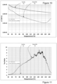
- Figure 10 illustrates a graph of complex viscosity (logarithmic vertical axis) vs temperature (linear horizontal axis), and figure 11 illustrates values of tan ⁇ (linear scales) for examples of materials for the first film 13a and second film 13b. More specifically, these materials are XLPO encapsulant developed in house at CSEM and XLPO grade ASCE supplied by Japanese company Mitsui chemicals, respectively. Throughout the whole graph, right up to approximately 165°C, the complex viscosity ⁇ * of the second film 13b does not even reach 50% of that of the first film 13a, and is hence well within limits of acceptability (80% maximum).
- lamination temperatures of up to about 165°C are hence possible, when tan ⁇ of the second film 13b falls below 0.9.
- the complex viscosity of the second film 13b should not exceed 10% of that of the first film 13a, and tan ⁇ of the second film 13b should remain above 1.2, indicating a maximum lamination temperature around 160°C however.
- the viscosity intrinsically decreases as the temperature increases, and hence the material of the second film 13b should be carefully chosen so as to endure a sufficient difference in viscosity throughout the entire lamination process, and the maximum temperature should likewise be carefully chosen. If required, e.g. for use in hot climates, the second film 13b can also be cross-linkable in order to have sufficient creep resistance.
- the first film 13a When the first film 13a is cross-linkable and it is not fully crosslinked after a pre-crosslinking step carried out earlier, it has a lower viscosity during early stages of lamination which helps to fill voids etc. before cross-linking increases its viscosity and gives it greater mechanical strength.
- its viscosity and Tan Delta depend on the temperature and the degree of reticulation (cross-linking) of the film, which may further develop as the lamination progresses.
- the intrinsic drop in viscosity and increase in Tan Delta as temperature increases are hence compensated by increasing reticulation, giving a much wider choice of material for the second film 13b since it is relatively easy to choose a material with a sufficiently-lower viscosity during the lamination process. Indeed, selection of a cross-linkable resin for the second film 13b for good creep resistance is easier in this case than in the case of a non-cross-linkable first film 13a.
- the interface between the two films 13a, 13b after lamination is perfect, and free of voids. Furthermore, cross-diffusion of the pigment particles 21 is minimal across the interface.
- First film 13a Second film 13b Padanaplast Polidan G420 Hangzhou First Enlight XUS 2. Mitsui Admer NF837E STR Solar 15530 3. Mitsui Admer NF410E Mitsui ASCE 4. Dow XUS 38660 (cross-linkable) Dai Nippon Printing (DNP) Solar CVF 5. ExxonMobil Escorene UL02528 CC (cross-linkable) Mitsui ASCE
- Figure 5 illustrates a graph of experimental results obtained by manufacturing a PV module 1 according to the embodiment of figure 2 but without the second zone 13b, in order to illustrate the effects of certain combinations of encapsulants and pigments.
- the front encapsulant layer 13 was made with Dow Engage PV POE XUS 38660.00 polyolefin-based base resin, 1 phr DuPont Ti-Pure R-960 titanium dioxide-based pigment, with no further additives. Median pigment particle size was 500 nm.
- the pigment particles were added and mixed manually with the base resin and extruded at 170°C by means of a twin-screw extruder to obtain a white cross-linkable polyolefin film with a thickness of 0.85mm.
- the resulting white front encapsulation sheet was combined with a 50 ⁇ m thick ETFE front sheet, and laminated onto a prefabricated PV module at a temperature of 165°C and pressure of approximately 1 bar ( ⁇ 0.99 bar) for 720 seconds.
- the metal connections of the PV module were blackened and the backsheet 19 was also black coloured to reduce contrast.
- the graph of figure 5 illustrates the external quantum efficiency (EQE) and reflectance (R) over the wavelength range of 350 nm to just over 1150nm, for the PV module 1 manufactured according to the invention as described immediately above (W1), and contrasted with a reference cell with the same construction but built using a clear front encapsulant layer 13 (R1). As can be seen, the EQE fell and the reflectance increased over a wide bandwidth of wavelengths of light.
- the module 1 thus constructed has a white colour, with current losses of approximately 58%.
- Figure 6 illustrates a graph of experimental results obtained by manufacturing another PV module 1 according to the embodiment of figure 2 (again without the underlying zone 13b), wherein the front encapsulant layer 13 was made with ExxonMobil Escorene Ultra UL 00728CC EVA copolymer base resin, with 0.05 wt.% of Scholz Red 110M pigment particles dispersed therein.
- the red pigment particles were mixed with the base resin manually, which was then extruded at 95°C to create a 0.9mm thick film of front encapsulant. This was then combined with a 100 ⁇ m thick ETFE front sheet and laminated at 150°C at a pressure of substantially 1 bar for 720 seconds. As per the previous example, the metal connections were blackened and a black coloured backsheet 19 was used.
- the resulting PV module has a terracotta colour particularly suitable for mounting on roofs in areas where terracotta tiles are common, and the graph of figure 6 again shows the EQE and reflectivity results obtained for this PV module (T2) compared to a similarly-constructed reference module (R2) using conventional clear front encapsulant.
- the EQE of the terracotta module T2 is only significantly diminished below about 650nm wavelength, and the reflectance profile only rises slightly above about 600nm wavelength.
- Figure 7 illustrates a graph of EQE
- figure 8 illustrates a graph of reflectance, with respect to wavelength of light obtained by PV modules constructed according to figure 1 (again without the underlying zone 13b).
- the base resin was Polidiemme FE1252 EP modified polyolefin from Padanaplast, and the pigment particles were Ti-Pure R-960 from DuPont, as mentioned above.
- the base resin and pigment were first compounded on a twin-screw extruder at 170°C and pelletised. Subsequently, the pellets were extruded at 170°C on a single-screw extruder to form films with the stated thickness.
- the PV module WD_3 represents a good tradeoff between performance and aesthetics.
- FIG. 1 As a final example, three modules according to the embodiment of figure 1 (again without the underlying zone 13b) with an applied image layer 29 according to figure 3 were fabricated.
- a reference module again comprised a clear front encapsulant 13, and then two others with front encapsulant layers 13 according to WD_3 and WD_4 as described above were also fabricated.
- the image graphic on the reference module was hardly visible, whereas it was clearly visible on the other two.
- the front encapsulant WD_3 represents a good compromise between aesthetics and power / current loss compared to an uncoloured reference.
- figure 9 illustrates a photovoltaic module 1 manufactured according to the invention mounted on the roof of a building structure 35.
- the PV module 1 can be mounted to an exterior wall, or integrated into the structure of the wall and/or roof, e.g. as cladding.
- the PV module 1 can be mounted on or in the structure of the building 35.
Landscapes
- Laminated Bodies (AREA)
- Photovoltaic Devices (AREA)
- Engineering & Computer Science (AREA)
- Manufacturing & Machinery (AREA)
Claims (8)
- Procédé de fabrication d'un module photovoltaïque (1) comprenant les étapes suivantes :- fournir un dispositif de laminage (33) ;- disposer dans ledit dispositif de laminage (33) un empilement de couches (31) comprenant :- une feuille avant (11) destinée à être disposée sur une face d'incidence lumineuse dudit module photovoltaïque (1) ;- une feuille arrière (19) destinée à être disposée sur une face dudit module photovoltaïque (1) opposée à ladite feuille avant (11) ;- un dispositif de conversion photovoltaïque (15) disposé entre ladite feuille avant (13) et ladite feuille arrière (19) ;- au moins une couche d'encapsulation avant (13) disposée entre ledit dispositif de conversion photovoltaïque (15) et ladite feuille avant (11), ladite couche d'encapsulation avant (13) comprenant des particules de pigment (21) réparties dans cette dernière ;- appliquer de la chaleur et de la pression à ladite pile de couches (31) afin de l'assembler dans ledit module photovoltaïque (1),dans lequel ladite couche d'encapsulation avant (13) comprend un premier film (13a) et un second film (13b), ledit premier film (13a) étant situé plus près de ladite feuille avant (11) que ledit second film (13b) et comprenant une concentration de particules de pigment plus élevée que ledit second film (13b),caractérisé en ce que ledit premier film (13a) est au moins partiellement réticulé et présente une viscosité complexe supérieure à 20'000 Pa.s à 85°C, supérieure à 15'000 Pa.s à 105°C, et supérieure à 5'000 Pa.s à 165°C, et dans lequel ledit second film (13b) présente une viscosité complexe inférieure à 100'000 Pa.s à 85°C, inférieure à 20'000 Pa.s à 105°C, et inférieure à 10'000 Pa.s à 165°C, les conditions de 165°C étant facultatives si la température de laminage est inférieure à 165°C.
- Procédé de fabrication d'un module photovoltaïque (1) comprenant les étapes suivantes- fournir un dispositif de laminage (29) ;- disposer dans ledit dispositif de laminage (29) une pile de couches comprenant :- un module photovoltaïque préfabriqué (27) ;- au moins une couche d'encapsulation avant (13) disposée sur une face d'incidence lumineuse dudit module photovoltaïque préfabriqué (27), ladite couche d'encapsulation avant (13) comprenant des particules de pigment (21) réparties dans cette dernière ;- une feuille avant (11) disposée sur une face d'incidence lumineuse de ladite au moins une couche d'encapsulation avant (13) ;- appliquer de la chaleur et de la pression à ladite pile de couches (31) afin de l'assembler dans ledit module photovoltaïque (1) ;caractérisé en ce que ladite couche d'encapsulation avant (13) comprend un premier film (13a) et un second film (13b), ledit premier film (13a) étant situé plus près de ladite feuille avant (11) que ledit second film (13b) et comprenant une concentration de particules de pigment plus élevée que ledit second film (13b).
- Procédé selon la revendication 1 ou 2, dans lequel ledit premier film (13a) a une viscosité plus élevée que ledit second film (13b) pendant ladite application de chaleur et de pression.
- Procédé selon la revendication 3, dans lequel ledit premier film (13a) a une valeur tan δ inférieure à 0,8, et ledit second film (13b) a une valeur tan δ d'au moins 0,9, de préférence d'au moins 1,2, pendant ladite application de chaleur et de pression, et dans lequel, à la température de laminage, la viscosité du second film (13b) est au plus égale à 80 %, de préférence au plus égale à 50 %, de la viscosité du premier film (13a).
- Procédé selon l'une des revendications 1 à 4, dans lequel au moins certaines desdites particules de pigment (21) ont un diamètre compris entre 100 nm et 1 µm, de préférence entre 300 et 700 nm, plus préférentiellement entre 400 et 600 nm.
- Procédé selon l'une des revendications 1 à 5, dans lequel lesdites particules de pigment (21) sont présentes dans ladite couche d'encapsulation frontale (13) dans une concentration massique allant de 0,01 à 10 parties pour cent de résine.
- Procédé selon l'une des revendications 1 à 6, dans lequel ledit pigment comprend au moins l'un de :- Pigments à base de zinc ;- Pigments à base de titane ;- Pigments à base de fer ;- Pigments à base de chrome ;- Pigments à base de bismuth ;- Pigments à base de cobalt ;- Pigments à base d'aluminium ;- Pigments à base d'étain ;- Pigments à base de cuivre.
- Procédé selon l'une des revendications 1 à 7, dans lequel ladite couche d'encapsulation avant (13) est fabriquée en mélangeant lesdites particules de pigment (21) avec une résine de base, et en extrudant ladite couche d'encapsulation avant (13) sous forme de film.
Applications Claiming Priority (2)
| Application Number | Priority Date | Filing Date | Title |
|---|---|---|---|
| PCT/EP2018/059637 WO2019201416A1 (fr) | 2018-04-16 | 2018-04-16 | Modules photovoltaïques et procédé de fabrication associé |
| PCT/EP2019/059422 WO2019201773A1 (fr) | 2018-04-16 | 2019-04-12 | Modules photovoltaïques et procédé de fabrication associé |
Publications (2)
| Publication Number | Publication Date |
|---|---|
| EP3782201A1 EP3782201A1 (fr) | 2021-02-24 |
| EP3782201B1 true EP3782201B1 (fr) | 2025-06-11 |
Family
ID=62002641
Family Applications (2)
| Application Number | Title | Priority Date | Filing Date |
|---|---|---|---|
| EP18718425.4A Pending EP3782199A1 (fr) | 2018-04-16 | 2018-04-16 | Modules photovoltaïques et procédé de fabrication associé |
| EP19717486.5A Active EP3782201B1 (fr) | 2018-04-16 | 2019-04-12 | Procédé de fabrication de modules photovoltaïques |
Family Applications Before (1)
| Application Number | Title | Priority Date | Filing Date |
|---|---|---|---|
| EP18718425.4A Pending EP3782199A1 (fr) | 2018-04-16 | 2018-04-16 | Modules photovoltaïques et procédé de fabrication associé |
Country Status (9)
| Country | Link |
|---|---|
| US (2) | US20210159352A1 (fr) |
| EP (2) | EP3782199A1 (fr) |
| JP (2) | JP2021521647A (fr) |
| KR (1) | KR102694947B1 (fr) |
| CN (2) | CN112005385A (fr) |
| CA (1) | CA3096728A1 (fr) |
| MA (1) | MA52282A (fr) |
| MY (1) | MY205953A (fr) |
| WO (2) | WO2019201416A1 (fr) |
Families Citing this family (63)
| Publication number | Priority date | Publication date | Assignee | Title |
|---|---|---|---|---|
| JPWO2021106872A1 (fr) * | 2019-11-25 | 2021-06-03 | ||
| WO2021106869A1 (fr) * | 2019-11-25 | 2021-06-03 | Agc株式会社 | Module de batterie solaire, son procédé de fabrication et matériau de paroi extérieure pour la construction utilisant ledit module de batterie solaire |
| US11398795B2 (en) | 2019-12-20 | 2022-07-26 | GAF Energy LLC | Roof integrated photovoltaic system |
| MX2022009069A (es) | 2020-01-22 | 2023-01-05 | GAF Energy LLC | Tejas para techos fotovoltaicas integradas, métodos, sistemas y kits de las mismas. |
| US11961928B2 (en) * | 2020-02-27 | 2024-04-16 | GAF Energy LLC | Photovoltaic module with light-scattering encapsulant providing shingle-mimicking appearance |
| CA3168489A1 (fr) * | 2020-02-27 | 2021-09-02 | Richard Perkins | Module photovoltaique avec agent d'encapsulation diffusant la lumiere fournissant un aspect imitant le bardeau |
| TWI730663B (zh) * | 2020-03-11 | 2021-06-11 | 南臺學校財團法人南臺科技大學 | 太陽能電池裝置及複合光學膜組 |
| CA3174671A1 (fr) | 2020-04-09 | 2021-10-14 | GAF Energy LLC | Module photovoltaique stratifie tridimensionnel |
| MX2022013519A (es) | 2020-04-30 | 2022-11-16 | GAF Energy LLC | Hoja frontal y hoja trasera de modulo fotovoltaico. |
| WO2021230938A1 (fr) | 2020-05-13 | 2021-11-18 | GAF Energy LLC | Passe-câble électrique |
| CN115769383A (zh) | 2020-06-04 | 2023-03-07 | Gaf能源有限责任公司 | 光伏屋顶板及其安装方法 |
| MX2023000952A (es) | 2020-07-22 | 2023-04-19 | GAF Energy LLC | Modulos fotovoltaicos. |
| MX2023001822A (es) | 2020-08-11 | 2023-05-08 | GAF Energy LLC | Sistema fotovoltaico montado en el techo y método para la transferencia inalámbrica de energía eléctrica. |
| MX2023002696A (es) | 2020-09-03 | 2023-05-24 | GAF Energy LLC | Sistema fotovoltaico integrado en edificios. |
| US11545928B2 (en) | 2020-10-13 | 2023-01-03 | GAF Energy LLC | Solar roofing system |
| EP4229750A4 (fr) | 2020-10-14 | 2024-11-13 | Gaf Energy LLC | Appareil de montage pour modules photovoltaïques |
| US11454027B2 (en) | 2020-10-29 | 2022-09-27 | GAF Energy LLC | System of roofing and photovoltaic shingles and methods of installing same |
| CA3197587A1 (fr) | 2020-11-12 | 2022-05-19 | Gabriela Bunea | Bardeaux de toiture a poignees |
| WO2022103841A1 (fr) | 2020-11-13 | 2022-05-19 | GAF Energy LLC | Systèmes et procédés pour modules photovoltaïques |
| CA3197427A1 (fr) * | 2020-11-18 | 2022-05-27 | Milan Padilla | Tuiles de toit photovoltaiques colorees |
| US11996797B2 (en) | 2020-12-02 | 2024-05-28 | GAF Energy LLC | Step flaps for photovoltaic and roofing shingles |
| US11459757B2 (en) | 2021-01-19 | 2022-10-04 | GAF Energy LLC | Watershedding features for roofing shingles |
| WO2022178311A1 (fr) | 2021-02-19 | 2022-08-25 | GAF Energy LLC | Module photovoltaïque pour toit avec bande continue de fibres |
| US12568694B2 (en) | 2021-03-19 | 2026-03-03 | GAF Energy LLC | Photovoltaic module with a laminated potted printed circuit board |
| WO2022212173A1 (fr) | 2021-03-29 | 2022-10-06 | GAF Energy LLC | Composants électriques pour systèmes photovoltaïques |
| JP7639497B2 (ja) * | 2021-04-05 | 2025-03-05 | 大日本印刷株式会社 | 太陽電池モジュール用封止材シートおよび太陽電池モジュール |
| CN113948597A (zh) * | 2021-04-30 | 2022-01-18 | 默克专利股份有限公司 | 制备彩色太阳能电池的方法 |
| US11527665B2 (en) | 2021-05-06 | 2022-12-13 | GAF Energy LLC | Photovoltaic module with transparent perimeter edges |
| MX2023014362A (es) | 2021-06-02 | 2023-12-15 | GAF Energy LLC | Modulo fotovoltaico con encapsulante de dispersion de la luz que proporciona una apariencia que imita a las tejas. |
| US12009781B2 (en) | 2021-07-06 | 2024-06-11 | GAF Energy LLC | Jumper module for photovoltaic systems |
| US11512480B1 (en) | 2021-07-16 | 2022-11-29 | GAF Energy LLC | Roof material storage bracket |
| US11728759B2 (en) | 2021-09-01 | 2023-08-15 | GAF Energy LLC | Photovoltaic modules for commercial roofing |
| WO2023141566A1 (fr) | 2022-01-20 | 2023-07-27 | GAF Energy LLC | Bardeaux de toiture pour imiter l'aspect de modules photovoltaïques |
| CA3188772A1 (fr) | 2022-02-08 | 2023-08-08 | GAF Energy LLC | Systeme photovoltaique integre au batiment |
| WO2023164494A1 (fr) | 2022-02-23 | 2023-08-31 | GAF Energy LLC | Bardeau de toiture et son procédé de fabrication |
| WO2023173019A1 (fr) | 2022-03-10 | 2023-09-14 | GAF Energy LLC | Encapsulant et feuille arrière combinés pour modules photovoltaïques |
| WO2023197010A1 (fr) | 2022-04-08 | 2023-10-12 | GAF Energy LLC | Connecteur à profil bas pour systèmes de toiture solaire |
| CA3257758A1 (fr) | 2022-06-06 | 2023-12-14 | GAF Energy LLC | Indicateurs de composants actifs pour systèmes photovoltaïques |
| WO2024015996A1 (fr) | 2022-07-15 | 2024-01-18 | GAF Energy LLC | Système de toiture solaire avec bardeaux de toiture composites en fibres |
| CA3264095A1 (fr) | 2022-08-24 | 2024-02-29 | GAF Energy LLC | Système de formation d'une membrane de toiture et procédé associé |
| EP4581684A1 (fr) | 2022-08-29 | 2025-07-09 | Gaf Energy LLC | Modules photovoltaïques à couches décalées |
| US12034089B2 (en) | 2022-09-01 | 2024-07-09 | GAF Energy LLC | Anti-reflective photovoltaic shingles and related methods |
| WO2024059462A1 (fr) | 2022-09-13 | 2024-03-21 | GAF Energy LLC | Système de toiture à capteurs et procédé associé |
| WO2024073288A1 (fr) | 2022-09-26 | 2024-04-04 | GAF Energy LLC | Modules photovoltaïques intégrés avec un parement et une clôture de bâtiment |
| US12143064B2 (en) | 2022-09-29 | 2024-11-12 | GAF Energy LLC | Jumper module with sleeve |
| WO2024091828A1 (fr) | 2022-10-25 | 2024-05-02 | GAF Energy LLC | Matériaux de toiture et procédés associés |
| US12231075B2 (en) | 2022-10-27 | 2025-02-18 | GAF Energy LLC | Building integrated photovoltaic systems |
| US12413183B2 (en) | 2022-11-15 | 2025-09-09 | GAF Energy LLC | Electrical cable passthrough for photovoltaic systems |
| US11811361B1 (en) | 2022-12-14 | 2023-11-07 | GAF Energy LLC | Rapid shutdown device for photovoltaic modules |
| CN115799401B (zh) * | 2022-12-29 | 2024-09-03 | 新源劲吾(北京)科技有限公司 | 一种利用真空吸附封装光伏组件的方法 |
| US12445089B2 (en) | 2023-02-03 | 2025-10-14 | GAF Energy LLC | Photovoltaic module, and associated kit, system, and method |
| US12355390B1 (en) | 2023-02-03 | 2025-07-08 | GAF Energy LLC | Solar shingle and associated roofing system and method |
| US12413174B2 (en) | 2023-02-21 | 2025-09-09 | GAF Energy LLC | Roofing system including photovoltaic module wireway cover, and associated method |
| US12176849B2 (en) | 2023-02-23 | 2024-12-24 | GAF Energy LLC | Photovoltaic shingles with multi-module power electronics |
| US12506440B2 (en) | 2023-02-28 | 2025-12-23 | GAF Energy LLC | Photovoltaic modules with energy storage components |
| CA3231973A1 (en) | 2023-03-14 | 2025-06-26 | GAF Energy LLC | Integrated cell and circuit interconnection |
| US12009782B1 (en) | 2023-04-04 | 2024-06-11 | GAF Energy LLC | Photovoltaic systems with wireways |
| US12413177B2 (en) | 2023-08-31 | 2025-09-09 | GAF Energy LLC | Photovoltaic modules and roofing shingles with nail zones |
| US12451838B1 (en) | 2023-10-06 | 2025-10-21 | GAF Energy LLC | Failsafe functionality for photovoltaic modules |
| WO2025090902A1 (fr) | 2023-10-26 | 2025-05-01 | GAF Energy LLC | Systèmes de toiture à protection contre l'entrée d'eau |
| WO2025122742A1 (fr) | 2023-12-05 | 2025-06-12 | GAF Energy LLC | Système de toiture pour la prévention de la déformation d'un bardeau de toiture |
| WO2025217150A1 (fr) | 2024-04-10 | 2025-10-16 | GAF Energy LLC | Bardeaux de toiture à structure ignifuge |
| US12540474B2 (en) | 2024-07-22 | 2026-02-03 | GAF Energy LLC | Electrically grounding metal roofing shingles with photovoltaic systems |
Citations (6)
| Publication number | Priority date | Publication date | Assignee | Title |
|---|---|---|---|---|
| JP2001308360A (ja) * | 2000-04-21 | 2001-11-02 | Sharp Corp | 太陽電池モジュール及びその製造方法 |
| EP2144301A1 (fr) * | 2008-07-09 | 2010-01-13 | Borealis AG | Module photovoltaïque comportant une couche d'isolation avec des groupes de silane |
| US20120024348A1 (en) * | 2010-07-30 | 2012-02-02 | E.I. Du Pont De Nemours And Company | Cross-linkable ionomeric encapsulants for photovoltaic cells |
| WO2012021460A2 (fr) * | 2010-08-07 | 2012-02-16 | Michael Eugene Young | Composants de dispositifs comprenant des additifs incorporés en surface et procédés de fabrication correspondants |
| EP2804223A1 (fr) * | 2012-01-13 | 2014-11-19 | Mitsubishi Plastics, Inc. | Module de cellule solaire doté d'une excellente apparence et son procédé de fabrication |
| US20150031812A1 (en) * | 2012-12-24 | 2015-01-29 | Lg Chem, Ltd. | Olefin resin composition |
Family Cites Families (33)
| Publication number | Priority date | Publication date | Assignee | Title |
|---|---|---|---|---|
| JP2613719B2 (ja) * | 1992-09-01 | 1997-05-28 | キヤノン株式会社 | 太陽電池モジュールの製造方法 |
| US5743970A (en) * | 1995-12-13 | 1998-04-28 | Energy Conversion Devices, Inc. | Photovoltaic module having an injection molded encapsulant |
| JP2001053298A (ja) * | 1999-08-09 | 2001-02-23 | Bridgestone Corp | 太陽電池用調色接着フィルム及び太陽電池 |
| JP2005079170A (ja) * | 2003-08-28 | 2005-03-24 | Kyocera Corp | 太陽電池モジュールおよびその製造方法 |
| US8319093B2 (en) | 2006-07-08 | 2012-11-27 | Certainteed Corporation | Photovoltaic module |
| US8404967B2 (en) * | 2008-01-08 | 2013-03-26 | Certainteed Corporation | Photovoltaic module |
| US20090288701A1 (en) * | 2008-05-23 | 2009-11-26 | E.I.Du Pont De Nemours And Company | Solar cell laminates having colored multi-layer encapsulant sheets |
| CN101787271A (zh) * | 2009-01-23 | 2010-07-28 | E.I.内穆尔杜邦公司 | 太阳能电池用量子点光波长转换层 |
| CN102422437B (zh) * | 2009-05-13 | 2016-05-04 | 三井-杜邦聚合化学株式会社 | 太阳能电池密封材料用片材及太阳能电池组件 |
| DE102010004439A1 (de) * | 2010-01-05 | 2011-07-07 | Steinbeis-Transferzentrum Angewandte Photovoltaik u. Dünnschichttechnik, 70197 | Solarzellenmodul |
| JP2012069865A (ja) * | 2010-09-27 | 2012-04-05 | Toppan Printing Co Ltd | 太陽電池封止材及びそれを用いた太陽電池モジュール |
| WO2012104668A1 (fr) * | 2011-01-31 | 2012-08-09 | Toray Films Europe | Film de polyester blanc multicouche, procédé de production du film et utilisation dudit film comme partie de feuille arrière pour cellules photovoltaïques |
| CN103429429B (zh) * | 2011-03-07 | 2016-06-08 | 富士胶片株式会社 | 易粘合板和用于太阳能电池的保护板 |
| US9281186B2 (en) * | 2011-03-31 | 2016-03-08 | Ats Automation Tooling Systems Inc. | Colored photovoltaic modules and methods of construction |
| WO2012152812A1 (fr) * | 2011-05-10 | 2012-11-15 | Basf Se | Nouveaux convertisseurs de couleur |
| FR2978526B1 (fr) * | 2011-07-29 | 2018-05-18 | Saint-Gobain Glass France | Vitrage multiple lumineux de batiment |
| JP2013133447A (ja) * | 2011-12-27 | 2013-07-08 | Toyo Ink Sc Holdings Co Ltd | 蛍光物質複合材料 |
| WO2013116688A1 (fr) * | 2012-02-03 | 2013-08-08 | The Regents Of The University Of California | Panneau luminescent générant de l'électricité pour la culture de plantes |
| JP5967593B2 (ja) * | 2012-06-27 | 2016-08-10 | パナソニックIpマネジメント株式会社 | 太陽電池モジュールの製造方法及び太陽電池モジュール |
| WO2014033829A1 (fr) * | 2012-08-28 | 2014-03-06 | 三洋電機株式会社 | Module de cellule solaire |
| EP2892080A4 (fr) * | 2012-08-31 | 2016-04-13 | Bridgestone Corp | Paire de films de scellage pour cellule solaire et procédé de fabrication de module de cellule solaire l'utilisant |
| EP2793271A1 (fr) | 2013-04-16 | 2014-10-22 | CSEM Centre Suisse d'Electronique et de Microtechnique SA - Recherche et Développement | Module photovoltaïque solaire |
| US10348239B2 (en) | 2013-05-02 | 2019-07-09 | 3M Innovative Properties Company | Multi-layered solar cell device |
| JP2014232792A (ja) * | 2013-05-29 | 2014-12-11 | 日東電工株式会社 | 波長変換型封止材層およびその製造方法 |
| JP6034756B2 (ja) * | 2013-06-21 | 2016-11-30 | 三井化学株式会社 | 太陽電池封止用シートセットおよびそれを用いた太陽電池モジュール |
| CN105612056A (zh) | 2013-10-15 | 2016-05-25 | 梅耶博格公司 | 用于形成层压板的方法和系统 |
| CN105900249B (zh) * | 2013-12-08 | 2017-09-22 | 太阳涂料有限公司 | 电极布置和用于在制备光伏表面时使用的套件 |
| WO2015129177A1 (fr) * | 2014-02-26 | 2015-09-03 | パナソニックIpマネジメント株式会社 | Module de cellule solaire |
| JP6446868B2 (ja) * | 2014-07-11 | 2019-01-09 | 大日本印刷株式会社 | 太陽電池モジュール用の封止材シート及びその製造方法 |
| WO2016118885A1 (fr) * | 2015-01-23 | 2016-07-28 | Sistine Solar, Inc. | Couches graphiques et procédés associés pour l'incorporation de couches graphiques dans des modules solaires |
| JP6716859B2 (ja) * | 2015-02-24 | 2020-07-01 | 大日本印刷株式会社 | 太陽電池モジュール用の有色封止材シート |
| JP2017212403A (ja) * | 2016-05-27 | 2017-11-30 | パナソニックIpマネジメント株式会社 | 太陽電池モジュール及びその製造方法 |
| JP2017135419A (ja) * | 2017-04-26 | 2017-08-03 | 大日本印刷株式会社 | 封止材シート |
-
2018
- 2018-04-16 WO PCT/EP2018/059637 patent/WO2019201416A1/fr not_active Ceased
- 2018-04-16 US US17/047,562 patent/US20210159352A1/en not_active Abandoned
- 2018-04-16 EP EP18718425.4A patent/EP3782199A1/fr active Pending
- 2018-04-16 CN CN201880092287.1A patent/CN112005385A/zh active Pending
-
2019
- 2019-04-12 US US17/047,569 patent/US20210159353A1/en not_active Abandoned
- 2019-04-12 CN CN201980025311.4A patent/CN112020776B/zh active Active
- 2019-04-12 JP JP2020555917A patent/JP2021521647A/ja active Pending
- 2019-04-12 WO PCT/EP2019/059422 patent/WO2019201773A1/fr not_active Ceased
- 2019-04-12 KR KR1020207030197A patent/KR102694947B1/ko active Active
- 2019-04-12 MA MA052282A patent/MA52282A/fr unknown
- 2019-04-12 CA CA3096728A patent/CA3096728A1/fr active Pending
- 2019-04-12 MY MYPI2020005317A patent/MY205953A/en unknown
- 2019-04-12 EP EP19717486.5A patent/EP3782201B1/fr active Active
-
2024
- 2024-06-11 JP JP2024094120A patent/JP7673297B2/ja active Active
Patent Citations (6)
| Publication number | Priority date | Publication date | Assignee | Title |
|---|---|---|---|---|
| JP2001308360A (ja) * | 2000-04-21 | 2001-11-02 | Sharp Corp | 太陽電池モジュール及びその製造方法 |
| EP2144301A1 (fr) * | 2008-07-09 | 2010-01-13 | Borealis AG | Module photovoltaïque comportant une couche d'isolation avec des groupes de silane |
| US20120024348A1 (en) * | 2010-07-30 | 2012-02-02 | E.I. Du Pont De Nemours And Company | Cross-linkable ionomeric encapsulants for photovoltaic cells |
| WO2012021460A2 (fr) * | 2010-08-07 | 2012-02-16 | Michael Eugene Young | Composants de dispositifs comprenant des additifs incorporés en surface et procédés de fabrication correspondants |
| EP2804223A1 (fr) * | 2012-01-13 | 2014-11-19 | Mitsubishi Plastics, Inc. | Module de cellule solaire doté d'une excellente apparence et son procédé de fabrication |
| US20150031812A1 (en) * | 2012-12-24 | 2015-01-29 | Lg Chem, Ltd. | Olefin resin composition |
Also Published As
| Publication number | Publication date |
|---|---|
| JP2024119918A (ja) | 2024-09-03 |
| WO2019201416A1 (fr) | 2019-10-24 |
| KR102694947B1 (ko) | 2024-08-13 |
| EP3782199A1 (fr) | 2021-02-24 |
| CN112005385A (zh) | 2020-11-27 |
| MY205953A (en) | 2024-11-21 |
| CN112020776A (zh) | 2020-12-01 |
| CA3096728A1 (fr) | 2019-10-24 |
| KR20200139708A (ko) | 2020-12-14 |
| JP2021521647A (ja) | 2021-08-26 |
| US20210159352A1 (en) | 2021-05-27 |
| WO2019201773A1 (fr) | 2019-10-24 |
| BR112020020834A2 (pt) | 2021-01-19 |
| CN112020776B (zh) | 2024-12-06 |
| US20210159353A1 (en) | 2021-05-27 |
| JP7673297B2 (ja) | 2025-05-08 |
| EP3782201A1 (fr) | 2021-02-24 |
| MA52282A (fr) | 2021-04-28 |
Similar Documents
| Publication | Publication Date | Title |
|---|---|---|
| EP3782201B1 (fr) | Procédé de fabrication de modules photovoltaïques | |
| US10295712B2 (en) | Backsheets for photovoltaic modules using infrared reflective pigments | |
| CN112385050A (zh) | 近红外反射性多层材料片材 | |
| EP3782202B1 (fr) | Modules photovoltaïques et leurs procédés de fabrication | |
| CN114350268A (zh) | 封装胶膜及光伏组件 | |
| KR20140015373A (ko) | 광기전 백시트 라미네이트, 광기전 백시트 라미네이트를 포함하는 광기전 모듈, 및 광기전 백시트 라미네이트의 제조방법 | |
| JP6604456B1 (ja) | 太陽電池モジュール用裏面保護シート及び太陽電池モジュール | |
| JP7356646B2 (ja) | 太陽電池モジュール用裏面保護シート及び太陽電池モジュール | |
| JP7690640B2 (ja) | 光電池モジュールの製造方法 | |
| BR112020020834B1 (pt) | Método de fabricação de um módulo fotovoltaico | |
| WO2020218485A1 (fr) | Feuille de protection de face arrière pour modules de cellules solaires, et module de cellules solaires | |
| JP2016068478A (ja) | 裏面保護シート |
Legal Events
| Date | Code | Title | Description |
|---|---|---|---|
| STAA | Information on the status of an ep patent application or granted ep patent |
Free format text: STATUS: UNKNOWN |
|
| STAA | Information on the status of an ep patent application or granted ep patent |
Free format text: STATUS: THE INTERNATIONAL PUBLICATION HAS BEEN MADE |
|
| PUAI | Public reference made under article 153(3) epc to a published international application that has entered the european phase |
Free format text: ORIGINAL CODE: 0009012 |
|
| STAA | Information on the status of an ep patent application or granted ep patent |
Free format text: STATUS: REQUEST FOR EXAMINATION WAS MADE |
|
| 17P | Request for examination filed |
Effective date: 20201102 |
|
| AK | Designated contracting states |
Kind code of ref document: A1 Designated state(s): AL AT BE BG CH CY CZ DE DK EE ES FI FR GB GR HR HU IE IS IT LI LT LU LV MC MK MT NL NO PL PT RO RS SE SI SK SM TR |
|
| AX | Request for extension of the european patent |
Extension state: BA ME |
|
| RIN1 | Information on inventor provided before grant (corrected) |
Inventor name: LI, HENGYU Inventor name: ESCARRE PALOU, JORDI Inventor name: SOEDERSTROEM, KARIN Inventor name: BULLIARD, XAVIER Inventor name: PERRET-AEBI, LAURE-EMMANUELLE Inventor name: BALLIF, CHRISTOPHE |
|
| DAX | Request for extension of the european patent (deleted) | ||
| RAV | Requested validation state of the european patent: fee paid |
Extension state: MA Effective date: 20201102 Extension state: TN Effective date: 20201102 |
|
| STAA | Information on the status of an ep patent application or granted ep patent |
Free format text: STATUS: EXAMINATION IS IN PROGRESS |
|
| 17Q | First examination report despatched |
Effective date: 20221021 |
|
| REG | Reference to a national code |
Ref country code: DE Ref legal event code: R079 Free format text: PREVIOUS MAIN CLASS: H01L0031048000 Ipc: H10F0019800000 Ref document number: 602019071010 Country of ref document: DE |
|
| GRAP | Despatch of communication of intention to grant a patent |
Free format text: ORIGINAL CODE: EPIDOSNIGR1 |
|
| STAA | Information on the status of an ep patent application or granted ep patent |
Free format text: STATUS: GRANT OF PATENT IS INTENDED |
|
| RIC1 | Information provided on ipc code assigned before grant |
Ipc: H10F 19/80 20250101AFI20250310BHEP |
|
| INTG | Intention to grant announced |
Effective date: 20250320 |
|
| GRAS | Grant fee paid |
Free format text: ORIGINAL CODE: EPIDOSNIGR3 |
|
| GRAA | (expected) grant |
Free format text: ORIGINAL CODE: 0009210 |
|
| STAA | Information on the status of an ep patent application or granted ep patent |
Free format text: STATUS: THE PATENT HAS BEEN GRANTED |
|
| AK | Designated contracting states |
Kind code of ref document: B1 Designated state(s): AL AT BE BG CH CY CZ DE DK EE ES FI FR GB GR HR HU IE IS IT LI LT LU LV MC MK MT NL NO PL PT RO RS SE SI SK SM TR |
|
| REG | Reference to a national code |
Ref country code: GB Ref legal event code: FG4D |
|
| REG | Reference to a national code |
Ref country code: CH Ref legal event code: EP |
|
| REG | Reference to a national code |
Ref country code: DE Ref legal event code: R096 Ref document number: 602019071010 Country of ref document: DE |
|
| REG | Reference to a national code |
Ref country code: IE Ref legal event code: FG4D |
|
| PG25 | Lapsed in a contracting state [announced via postgrant information from national office to epo] |
Ref country code: ES Free format text: LAPSE BECAUSE OF FAILURE TO SUBMIT A TRANSLATION OF THE DESCRIPTION OR TO PAY THE FEE WITHIN THE PRESCRIBED TIME-LIMIT Effective date: 20250611 Ref country code: FI Free format text: LAPSE BECAUSE OF FAILURE TO SUBMIT A TRANSLATION OF THE DESCRIPTION OR TO PAY THE FEE WITHIN THE PRESCRIBED TIME-LIMIT Effective date: 20250611 |
|
| REG | Reference to a national code |
Ref country code: LT Ref legal event code: MG9D |
|
| PG25 | Lapsed in a contracting state [announced via postgrant information from national office to epo] |
Ref country code: NO Free format text: LAPSE BECAUSE OF FAILURE TO SUBMIT A TRANSLATION OF THE DESCRIPTION OR TO PAY THE FEE WITHIN THE PRESCRIBED TIME-LIMIT Effective date: 20250911 Ref country code: GR Free format text: LAPSE BECAUSE OF FAILURE TO SUBMIT A TRANSLATION OF THE DESCRIPTION OR TO PAY THE FEE WITHIN THE PRESCRIBED TIME-LIMIT Effective date: 20250912 |
|
| REG | Reference to a national code |
Ref country code: NL Ref legal event code: MP Effective date: 20250611 |
|
| PG25 | Lapsed in a contracting state [announced via postgrant information from national office to epo] |
Ref country code: BG Free format text: LAPSE BECAUSE OF FAILURE TO SUBMIT A TRANSLATION OF THE DESCRIPTION OR TO PAY THE FEE WITHIN THE PRESCRIBED TIME-LIMIT Effective date: 20250611 |
|
| PG25 | Lapsed in a contracting state [announced via postgrant information from national office to epo] |
Ref country code: HR Free format text: LAPSE BECAUSE OF FAILURE TO SUBMIT A TRANSLATION OF THE DESCRIPTION OR TO PAY THE FEE WITHIN THE PRESCRIBED TIME-LIMIT Effective date: 20250611 |
|
| PG25 | Lapsed in a contracting state [announced via postgrant information from national office to epo] |
Ref country code: RS Free format text: LAPSE BECAUSE OF FAILURE TO SUBMIT A TRANSLATION OF THE DESCRIPTION OR TO PAY THE FEE WITHIN THE PRESCRIBED TIME-LIMIT Effective date: 20250911 |
|
| PG25 | Lapsed in a contracting state [announced via postgrant information from national office to epo] |
Ref country code: LV Free format text: LAPSE BECAUSE OF FAILURE TO SUBMIT A TRANSLATION OF THE DESCRIPTION OR TO PAY THE FEE WITHIN THE PRESCRIBED TIME-LIMIT Effective date: 20250611 |
|
| PG25 | Lapsed in a contracting state [announced via postgrant information from national office to epo] |
Ref country code: NL Free format text: LAPSE BECAUSE OF FAILURE TO SUBMIT A TRANSLATION OF THE DESCRIPTION OR TO PAY THE FEE WITHIN THE PRESCRIBED TIME-LIMIT Effective date: 20250611 |
|
| PG25 | Lapsed in a contracting state [announced via postgrant information from national office to epo] |
Ref country code: PT Free format text: LAPSE BECAUSE OF FAILURE TO SUBMIT A TRANSLATION OF THE DESCRIPTION OR TO PAY THE FEE WITHIN THE PRESCRIBED TIME-LIMIT Effective date: 20251013 |
|
| REG | Reference to a national code |
Ref country code: AT Ref legal event code: MK05 Ref document number: 1803298 Country of ref document: AT Kind code of ref document: T Effective date: 20250611 |
|
| PG25 | Lapsed in a contracting state [announced via postgrant information from national office to epo] |
Ref country code: IS Free format text: LAPSE BECAUSE OF FAILURE TO SUBMIT A TRANSLATION OF THE DESCRIPTION OR TO PAY THE FEE WITHIN THE PRESCRIBED TIME-LIMIT Effective date: 20251011 |
|
| PG25 | Lapsed in a contracting state [announced via postgrant information from national office to epo] |
Ref country code: AT Free format text: LAPSE BECAUSE OF FAILURE TO SUBMIT A TRANSLATION OF THE DESCRIPTION OR TO PAY THE FEE WITHIN THE PRESCRIBED TIME-LIMIT Effective date: 20250611 Ref country code: SM Free format text: LAPSE BECAUSE OF FAILURE TO SUBMIT A TRANSLATION OF THE DESCRIPTION OR TO PAY THE FEE WITHIN THE PRESCRIBED TIME-LIMIT Effective date: 20250611 |
|
| PG25 | Lapsed in a contracting state [announced via postgrant information from national office to epo] |
Ref country code: CZ Free format text: LAPSE BECAUSE OF FAILURE TO SUBMIT A TRANSLATION OF THE DESCRIPTION OR TO PAY THE FEE WITHIN THE PRESCRIBED TIME-LIMIT Effective date: 20250611 |
|
| PG25 | Lapsed in a contracting state [announced via postgrant information from national office to epo] |
Ref country code: PL Free format text: LAPSE BECAUSE OF FAILURE TO SUBMIT A TRANSLATION OF THE DESCRIPTION OR TO PAY THE FEE WITHIN THE PRESCRIBED TIME-LIMIT Effective date: 20250611 |
|
| PG25 | Lapsed in a contracting state [announced via postgrant information from national office to epo] |
Ref country code: EE Free format text: LAPSE BECAUSE OF FAILURE TO SUBMIT A TRANSLATION OF THE DESCRIPTION OR TO PAY THE FEE WITHIN THE PRESCRIBED TIME-LIMIT Effective date: 20250611 |
|
| PG25 | Lapsed in a contracting state [announced via postgrant information from national office to epo] |
Ref country code: RO Free format text: LAPSE BECAUSE OF FAILURE TO SUBMIT A TRANSLATION OF THE DESCRIPTION OR TO PAY THE FEE WITHIN THE PRESCRIBED TIME-LIMIT Effective date: 20250611 Ref country code: SK Free format text: LAPSE BECAUSE OF FAILURE TO SUBMIT A TRANSLATION OF THE DESCRIPTION OR TO PAY THE FEE WITHIN THE PRESCRIBED TIME-LIMIT Effective date: 20250611 |
|
| PGFP | Annual fee paid to national office [announced via postgrant information from national office to epo] |
Ref country code: GB Payment date: 20260324 Year of fee payment: 8 |
|
| PG25 | Lapsed in a contracting state [announced via postgrant information from national office to epo] |
Ref country code: DK Free format text: LAPSE BECAUSE OF FAILURE TO SUBMIT A TRANSLATION OF THE DESCRIPTION OR TO PAY THE FEE WITHIN THE PRESCRIBED TIME-LIMIT Effective date: 20250611 |
|
| PG25 | Lapsed in a contracting state [announced via postgrant information from national office to epo] |
Ref country code: IT Free format text: LAPSE BECAUSE OF FAILURE TO SUBMIT A TRANSLATION OF THE DESCRIPTION OR TO PAY THE FEE WITHIN THE PRESCRIBED TIME-LIMIT Effective date: 20250611 |
|
| PLBE | No opposition filed within time limit |
Free format text: ORIGINAL CODE: 0009261 |
|
| STAA | Information on the status of an ep patent application or granted ep patent |
Free format text: STATUS: NO OPPOSITION FILED WITHIN TIME LIMIT |
|
| REG | Reference to a national code |
Ref country code: CH Ref legal event code: L10 Free format text: ST27 STATUS EVENT CODE: U-0-0-L10-L00 (AS PROVIDED BY THE NATIONAL OFFICE) Effective date: 20260423 |