EP3782251B1 - Verbesserte lichtbogenfehlerdetektion mittels zeitsegmentierter erfassung - Google Patents
Verbesserte lichtbogenfehlerdetektion mittels zeitsegmentierter erfassung Download PDFInfo
- Publication number
- EP3782251B1 EP3782251B1 EP19800515.9A EP19800515A EP3782251B1 EP 3782251 B1 EP3782251 B1 EP 3782251B1 EP 19800515 A EP19800515 A EP 19800515A EP 3782251 B1 EP3782251 B1 EP 3782251B1
- Authority
- EP
- European Patent Office
- Prior art keywords
- signal
- high frequency
- arc fault
- spectrum
- segment
- Prior art date
- Legal status (The legal status is an assumption and is not a legal conclusion. Google has not performed a legal analysis and makes no representation as to the accuracy of the status listed.)
- Active
Links
Images




Classifications
-
- G—PHYSICS
- G01—MEASURING; TESTING
- G01R—MEASURING ELECTRIC VARIABLES; MEASURING MAGNETIC VARIABLES
- G01R31/00—Arrangements for testing electric properties; Arrangements for locating electric faults; Arrangements for electrical testing characterised by what is being tested not provided for elsewhere
- G01R31/08—Locating faults in cables, transmission lines, or networks
- G01R31/081—Locating faults in cables, transmission lines, or networks according to type of conductors
- G01R31/085—Locating faults in cables, transmission lines, or networks according to type of conductors in power transmission or distribution lines, e.g. overhead
-
- G—PHYSICS
- G01—MEASURING; TESTING
- G01R—MEASURING ELECTRIC VARIABLES; MEASURING MAGNETIC VARIABLES
- G01R31/00—Arrangements for testing electric properties; Arrangements for locating electric faults; Arrangements for electrical testing characterised by what is being tested not provided for elsewhere
- G01R31/12—Testing dielectric strength or breakdown voltage ; Testing or monitoring effectiveness or level of insulation, e.g. of a cable or of an apparatus, for example using partial discharge measurements; Electrostatic testing
- G01R31/1227—Testing dielectric strength or breakdown voltage ; Testing or monitoring effectiveness or level of insulation, e.g. of a cable or of an apparatus, for example using partial discharge measurements; Electrostatic testing of components, parts or materials
- G01R31/1263—Testing dielectric strength or breakdown voltage ; Testing or monitoring effectiveness or level of insulation, e.g. of a cable or of an apparatus, for example using partial discharge measurements; Electrostatic testing of components, parts or materials of solid or fluid materials, e.g. insulation films, bulk material; of semiconductors or LV electronic components or parts; of cable, line or wire insulation
- G01R31/1272—Testing dielectric strength or breakdown voltage ; Testing or monitoring effectiveness or level of insulation, e.g. of a cable or of an apparatus, for example using partial discharge measurements; Electrostatic testing of components, parts or materials of solid or fluid materials, e.g. insulation films, bulk material; of semiconductors or LV electronic components or parts; of cable, line or wire insulation of cable, line or wire insulation, e.g. using partial discharge measurements
-
- H—ELECTRICITY
- H02—GENERATION; CONVERSION OR DISTRIBUTION OF ELECTRIC POWER
- H02H—EMERGENCY PROTECTIVE CIRCUIT ARRANGEMENTS
- H02H1/00—Details of emergency protective circuit arrangements
- H02H1/0007—Details of emergency protective circuit arrangements concerning the detecting means
- H02H1/0015—Using arc detectors
-
- H—ELECTRICITY
- H02—GENERATION; CONVERSION OR DISTRIBUTION OF ELECTRIC POWER
- H02H—EMERGENCY PROTECTIVE CIRCUIT ARRANGEMENTS
- H02H7/00—Emergency protective circuit arrangements specially adapted for specific types of electric machines or apparatus or for sectionalised protection of cable or line systems, and effecting automatic switching in the event of an undesired change from normal working conditions
- H02H7/26—Sectionalised protection of cable or line systems, e.g. for disconnecting a section on which a short-circuit, earth fault, or arc discharge has occured
-
- G—PHYSICS
- G06—COMPUTING OR CALCULATING; COUNTING
- G06F—ELECTRIC DIGITAL DATA PROCESSING
- G06F2218/00—Aspects of pattern recognition specially adapted for signal processing
- G06F2218/02—Preprocessing
-
- G—PHYSICS
- G06—COMPUTING OR CALCULATING; COUNTING
- G06F—ELECTRIC DIGITAL DATA PROCESSING
- G06F2218/00—Aspects of pattern recognition specially adapted for signal processing
- G06F2218/08—Feature extraction
-
- G—PHYSICS
- G06—COMPUTING OR CALCULATING; COUNTING
- G06F—ELECTRIC DIGITAL DATA PROCESSING
- G06F2218/00—Aspects of pattern recognition specially adapted for signal processing
- G06F2218/12—Classification; Matching
Definitions
- Power line communication (PLC) devices can be used in buildings, such as a residential home (e.g., house, condominium, apartment, etc.), to enable data communications across a power system infrastructure, such as power lines of a branch circuit(s) or between different branches.
- PLC devices conduct communications in frequency ranges, such as for example in some given regulatory jurisdictions range from 1.8MHz to 30MHz and to as high as 86MHz (see, e.g., HomePlug Avx and HomePlug GreenPhy).
- Power line communication protocol used by PLC devices can include, for example, IEEE 1901, IEEE P1901.2, HomePlug GP/AV/AV2/1.0, G.hn, or G.hnem.
- PLC devices When PLC devices are employed in a building or other structure along with an arc fault circuit interrupter (AFCI) device, the presence of PLC signals, particularly the high frequency signal content of their carrier signals may be inadvertently interpreted by the AFCI device as arc fault signals, and thus, may result in nuisance trips by the AFCI device. Accordingly, PLC signals and other high frequency noises may interfere with arc fault detection at the high frequency ranges, e.g., frequency ranges greater than or equal to 1MHz which can potentially mask any arcing signals.
- AFCI arc fault circuit interrupter
- RSSI Receive Signal Strength Indicator
- Another detection method involves selecting a frequency region (e.g., region, band, etc.) that corresponds to one of the notch bands of the power line carriers.
- the notch bands represent narrow frequency regions that are not enabled or used by the PLC device to conduct communication.
- a detection method allows only a small window, e.g., the narrow frequency region, for the arcing signals to be detected.
- a frequency region might be used by radio stations (e.g., amateur radio) or correspond to a network impedance (resonance/anti-resonance) point which could cause substantial sensitivity issues.
- a detection method according to claim 1 and a device according to claim 8 are provided to detect an arc fault signal from a high frequency signal on a power line.
- the system samples a high frequency signal from the power line over a predefined time period such as a half-cycle, and partitions the sampled high frequency signal into signal segments of smaller time intervals over the predefined time period.
- the arc fault detection system partitions the monitored high frequency signal into a sequence of time-segmented signal segments, where N can equal a maximum number of signal segments for the high frequency signal within the predefined time period.
- the system filters out frequency regions known to carry power line communication (PLC) in each signal segment, and determines whether high frequency signal content, which may reflect an arc fault signal, is present or not in each filtered signal segment. In this way, a high frequency signal content distribution over the predefined time period can be obtained for the sampled high frequency signal in which PLC frequency regions have been filtered out in each signal segment.
- the system can then detect for a presence or absence of an arc fault signal based on the content distribution of the filtered signal segments over the predefined time period. For example, an arc fault signal is detected if the number of filtered signal segments having high frequency signal content within the predefined time period satisfies a threshold condition. When an arc fault signal is detected, power to the power line is interrupted.
- PLC power line communication
- the system can monitor and evaluate signals in the high frequency range on the power line, a range which is generally less noisy and less subject to noise injection from load(s) than the lower frequency ranges.
- the system also can discriminate common high frequency load noise and power line carriers in order to facilitate high frequency monitoring of arc fault signals on a power line.
- a high frequency signal is monitored on a power line over a first predefined time period (e.g., a half-cycle of a base frequency), and the high frequency signal is partitioned into a plurality of time-segmented signal segments of smaller time intervals over the predefined time period.
- the system 1) applies a first filter to a signal spectrum of the signal segment to produce a first filtered signal spectrum with one or more frequency intervals associated with power line communication filtered from the signal spectrum, 2) checks for high frequency signal content in the first filtered signal spectrum of the signal segment, and 3) assigns a first binary value to the signal segment based upon a presence or absence of high frequency signal content in the first filtered signal spectrum.
- a signal spectrum is a representation of a signal, for example, in a frequency domain. Thereafter, a determination is made whether the high frequency signal includes an arc fault signal based on the first binary values of the plurality of signal segments in the first predefined time period. When an arc fault signal is detected, power is interrupted on the power line.
- the system can be implemented in a circuit breaker.
- the first filter can be a mask (also referred to as a first mask), which is for example a pattern of bits used to accept or reject bit patterns in another set of data.
- the first mask can be applied to a data set of a signal spectrum, such as in the frequency domain, to compute a filtered signal spectrum which accepts or rejects the frequency intervals (or values thereof) associated with power line communication.
- the pattern of the mask can be represented in vector form, e.g., a mask vector.
- the system when assigning a first binary value for each signal segment, can be further configured to determine a relative magnitude of energy of the first filtered signal spectrum of the signal segment; to compare the relative magnitude of energy to a first spectrum energy threshold for determining a presence or absence of high frequency signal content in the signal segment; and to assign the first binary value to the signal segment based on the comparison. For example, a binary value of "1" can be assigned to a segment with a determined presence of high frequency signal content.
- the system can be further configured to apply a second filter (e.g., a second mask), which is an inverse of the first filter, to a signal spectrum of the signal segment in order to produce a second filtered signal spectrum having one or more frequency intervals associated with power line communication.
- a second filter e.g., a second mask
- the system can then check for high frequency signal content in the second filtered signal spectrum of the signal segment, and assign a second binary value to the signal segment based upon a presence or absence of high frequency signal content in the second filtered signal spectrum of the signal segment.
- the system can further adjust the first spectrum energy threshold based on the second binary values of the plurality of signal segments in the first period.
- the adjusted first spectrum energy threshold is used to evaluate high frequency signal on the power line in a time period after the first predefined time period.
- the system can be configured to determine a relative magnitude of energy of the second filtered signal spectrum of the signal segment; to compare the relative magnitude of energy of the second filtered signal spectrum to a second spectrum energy threshold for determining a presence or absence of high frequency signal content in the signal segment; and to assign the second binary value to the signal segment based on the comparison.
- the arc fault detection sensitivity of the system can be dynamically adjusted to compensate for the presence or absence of PLC noise or other benign noise on the power line network, e.g., by adjusting the first spectrum energy threshold.
- the system is configured to count a number of times that high frequency signal content is present over the predefined time period based on the first binary values; to compare the number of times that high frequency signal content is present (in the first filtered signal spectrum of each signal segment) over the predefined time period to at least a first high frequency threshold; and to detect an arc fault signal when a condition for the first high frequency threshold is satisfied.
- the first high frequency threshold can be associated with load on the power line (e.g., a load threshold), and a second high frequency threshold can be associated with arcing on the power line (e.g., an arc threshold).
- the system is further configured to compare the number of times that high frequency signal content is present (in the first filtered signal spectrum of each signal segment) over the predefined time period to the second high frequency threshold when the first high frequency threshold is satisfied.
- the system can detect an arc fault signal when both conditions for the first and second high frequency thresholds are satisfied.
- the system is configured to generate a binary word from a sequence of the first binary values for the signal segments from the first predefined time period.
- the system further evaluates the binary word to detect for an occurrence of an arc fault signal.
- the binary word can be compared to one or more predefined word patterns to detect for an occurrence or non-occurrence of an arc fault signal in the high frequency signal.
- the predefined word patterns can correspond to known patterns for an arc fault event or non-arc fault event (e.g., a load event).
- the predefined time period can be a half-cycle of a base frequency (e.g., 50 or 60 Hz of the power line frequency).
- a signal spectrum in the frequency domain can be generated for each signal segment using a Fourier Transform or a Cosine Transform, and all monitoring, partitioning, applying, checking, assigning and determining operations can be performed in a circuit breaker if desired.
- An arc fault detection method and system (again, hereinafter just “system”) are provided, which monitor and analyze high frequency signals on a power line of a circuit to detect arc fault signals on the power line, even where high frequency components are generated on the power line by sources other than an arc fault, such as power line communication and other common radio frequency (RF) communication (e.g., amateur radio) in the high frequency range.
- the system is configured to partition a high frequency signal monitored on the power line over a predefined time period (e.g., a half-cycle of a base frequency) into a plurality of signal segments of smaller time within the predefined time period.
- the signal segments are then evaluated for a presence of high frequency signal content in the frequency ranges or regions of interest.
- a filter e.g., a mask
- the mask can be applied to the spectrum of a signal segment to produce a filtered signal spectrum by ignoring carrier energy in benign frequency regions of the signal spectrum, e.g., intervals or bins for PLC carriers, when examining for the arc fault signal content.
- the system can apply a binary classification to each signal segment to obtain a signal content distribution over the predefined time period.
- the signal segments are each assigned a binary value, e.g., 0 or 1, which identifies a presence or absence of high frequency signal content of interest in a signal segment according to a relative magnitude of the energy of the filtered signal spectrum.
- the system can then detect a presence of arc fault signals on the power line based on the binary values for the signal segments over the predefined time period.
- the system can determine an existence (or non-existence) of an arc fault signal in the high frequency signal when the binary values reflect a presence of potential arc fault signal content in a significant number of the signal segments or a particular pattern of binary values (e.g., a particular binary word) over the predefined time period.
- a trip mechanism e.g., a switch, etc.
- the system herein can perform arc fault detection in a high frequency region (e.g., greater than 1MHz, or between 1 MHz and 100MHz) which generally contains less load noise than lower frequency regions on a power line, while reducing the possibility of nuisance arc fault detection and trips that may result from PLC communication or other common high frequency noise.
- the system can also be implemented in a circuit breaker or in combination with a circuit breaker in an efficient and cost effective fashion. Examples of these and other features of the system will be described below with reference to the examples in Figs. 1-13 .
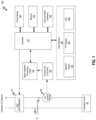
- Fig. 1 illustrates a block diagram of a circuit breaker 100 with an arc fault detection system for monitoring high frequency signal on an AC power line 10 (e.g., with a base frequency of 50 or 60 Hz power line) of a protected circuit 20.
- the circuit breaker 100 includes a controller 110, an analog front end (AFE) 120 to receive signals from a high frequency (HF) current sensor 180, a signal segment processing logic 122, a memory 130, communication interfaces 140 to communicate with remote devices over a communication medium, a user interface 150, a power supply 160 to power the components of the circuit breaker 100, and a trip mechanism 170 to interrupt power on the power line 10 upstream of the protected circuit 20.
- AFE analog front end
- the user interface 150 can include an ON/OFF switch 152 (e.g., a handle), a push-to-test (PTT) button to test the circuit breaker, and one or more LEDs 156 or other indicators for indicating a status of the circuit breaker (e.g., ON, OFF, RESET, TRIPPED, etc.) or other circuit breaker information.
- the HF current sensor 180 can be a high frequency current sensor such as a Rogowski coil or other sensor to measure high frequency signals on the power line.
- the analog front end 120 In the circuit breaker 100, the analog front end 120, the signal segment processing logic 122, the controller 110 and memory 130 can operate together to provide an arc fault detection system, which is configured to detect arc fault signals in a high frequency range on the power line 10.
- the analog front end 120 is configured to receive and monitor high frequency signals in desired high frequency region(s) from the HF current sensor 180, and can be a radio frequency (RF) receiver that includes a bandpass filter(s).
- RF radio frequency
- the operations of the signal segment processing logic 122 can be implemented in an ASIC or FPGA or other dedicated signal processing module.
- the signal segment processing logic 122 operates to partition the high frequency signal, received through the analog front end 120 over a predefined time period (e.g., a half-cycle of a base frequency), into a plurality of time-segmented signal segments of smaller time intervals, and to detect a presence or absence of high frequency signal content in frequency regions of interest in each signal segment.
- the signal segment processing logic 122 can generate a signal spectrum for each signal segment, and then implement two parallel sub-processes on the signal spectrum to detect for two different types of signal content in each signal segment.
- a signal spectrum is a representation of the signal in a desired domain (e.g., frequency domain).
- One sub-process referred to herein as "ARC" sub-process, is used to detect for potential arc fault frequency signal components in each signal segment in order to detect for a presence or absence of an arc fault signal on a power line.
- the other sub-process is used to detect for a PLC frequency signal component (and other benign noise if desired) in each signal segment in order to dynamically adjust a sensitivity level of the detection for arc fault signal components performed by the ARC sub-process (e.g., by adjusting a spectrum energy threshold (th a )) in view of a noise level on the power line network.
- the signal segment processing logic 122 can output an ARC binary value via the ARC sub-process to reflect a presence or absence of potential arc fault signal component for each signal segment, and can output a HF binary value via the HF sub-process to reflect a presence or absence of a PLC frequency signal component or other benign noise.
- the signal segment processing logic 122 can also output an accumulated value of all of the binary values for each sub-process over the predefined time period, e.g., ARC accumulation and HF accumulation.
- ARC and HF are simply used in some instances herein as an adjective to describe the processes or data associated with the respective sub-processes.
- Example operations of the signal segment processing logic 122, including their sub-processes, are described in greater detail below with reference to Figs. 3 through 8 .
- the controller 110 is configured to receive the binary value(s), accumulation of the binary values for the ARC and HF sub-processes, or data associated therewith for each signal segment, to detect a presence or absence of an arc fault signal in the monitored high frequency signal based on the ARC binary values, and to adjust a signal spectrum threshold applied by the ARC sub-process of the signal segment processing logic 112.
- the controller 110 is also configured to initiate a circuit breaker trip operation, which interrupts power on the power line 10 via the trip mechanism 170 under certain conditions, including when the presence of an arc fault signal is detected.
- the controller is also configured to control other operations of the circuit breaker 100 including communication via the communication interfaces 140 (e.g., to receive or transmit commands or status information/reports), to perform operations based on actions input by a user through the user interface 150, to output a status of the circuit breaker such as via the LED 156 or other output device, and to perform other operations of the circuit breaker related to arc fault detection and power interruption.
- Example operations of the controller 110 are described in greater detail below with reference to Figs. 9 through 11 .
- the memory 130 can store computer executable code or programs or software, which when executed by the controller 110, controls the operations of the circuit breaker 100 including the arc fault detection operations and other circuit breaker operations such as circuit interruption.
- the memory 130 can also store other data used by the circuit breaker 100 or components thereof to perform the operations described herein.
- the other data can include but is not limited to thresholds, filters/masks, threshold hysteresis, other circuit breaker data, and other data discussed herein.
- Fig. 2 illustrates a block diagram of the components of the analog front end 120 and the signal segment processing logic 122 of the arc fault detection system of Fig. 1 , in accordance with an example embodiment of the present disclosure.
- the analog front end 120 can include a radio frequency (RF) front end 200, such as an RF receiver, and a bandpass filter 202, which together perform signal conditioning and narrow the frequency range of the signal received by the RF front end 200 from the HF current sensor 180.
- RF radio frequency
- the signal segment processing logic 122 can include an analog-to-digital converter (ADC) 210 to convert the analog signal from the analog front end 120 to a digital signal for signal segment processing by a segment processing module 220.
- the ADC 210 can, for example, have a sampling rate at a Nyquist rate of the maximum frequency range (e.g., twice 100MHz). For example, at 100MHz, these signals are not attenuated significantly, and thus, they can be detected with a HF current sensor or the like. On the sampling side, the Nyquist sampling rate can be at least 200MHz to observe content on the 100MHz signals.
- the limit of 100MHz is an arbitrary maximum limit.
- the arc fault detection system herein can operate with 30MHz to detect most of PLC AV1 and Green PHY carriers, and with 100MHz to detect AV2.0.
- the segment processing module 220 can be configured to perform the various signal processing functions and features of the signal segment processing logic 122, as described herein.
- the controller 110 receives the output from the signal segment processing logic 122, e.g., ARC binary values and/or HF binary values for the signal segments of the monitored high frequency signal on the power line 10.
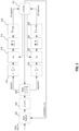
- Fig. 3 illustrates a functional block diagram of the components of a signal segment processing logic 122 of the arc fault detection system, such as in Figs. 1 and 2 , which obtains and performs signal segment processing on each signal segment of a high frequency signal monitored over a predefined time period (e.g., a half-cycle of the base frequency of the power transmission), in accordance with an example embodiment of the present disclosure.
- a signal segment processing logic 122 of the arc fault detection system such as in Figs. 1 and 2 , which obtains and performs signal segment processing on each signal segment of a high frequency signal monitored over a predefined time period (e.g., a half-cycle of the base frequency of the power transmission), in accordance with an example embodiment of the present disclosure.
- a signal segment is obtained (e.g., from ADC 210 in Fig. 2 ).
- a signal spectrum is generated for each signal segment.
- the signal segment is processed using a Fast Fourier Transform, e.g., an FFT module, which computes a magnitude of the signal spectrum for the signal segment.
- two separate masks, a HF mask and an ARC mask are applied to the signal spectrum of the signal segment to produce respective filtered signal spectrums, which are to be processed in parallel.
- the ARC mask is used in the ARC sub-process to generate an ARC filtered signal spectrum (e.g., x a ) of the signal segment without or ignoring the frequency regions associated with power line communication.
- the HF mask is used in the HF sub-process to generate a HF filtered signal spectrum of the signal segment having the frequency regions associated with power line communication.
- the ARC filtered signal spectrum can be provided to an auto-correlator (ACR) to determine a maximum peak of the magnitude, which can instead be used as the relative magnitude.
- ACR auto-correlator
- the ACR can compute the energy which is equivalent to the summation of squares of the samples, e.g., computing the energy of the signal spectrum vector after the mask is applied.
- the relative magnitude is compared against a spectrum energy threshold, e.g., th a (see Fig. 9 ) to determine a presence or absence of high frequency signal content in the ARC filtered signal spectrum.
- the ARC filtered signal spectrum is converted to a binary value to reflect the presence or absence of high frequency signal content therein, e.g., in this case, potential arc fault signal components.
- the ARC filtered signal spectrum is assigned a binary value of "1" when the relative magnitude reflects the presence of high frequency signal content in the ARC filtered signal spectrum, and is assigned a binary value of "0" when the relative magnitude reflects the absence of high frequency signal content in the ARC filtered signal spectrum, or vice-a-versa.
- the above-noted blocks 320, 322 and 324 are repeated for the entire number of signal segments (e.g., N) allocated within the predefined time period (e.g., a half-cycle of the base frequency).
- the collection of binary value outputs is fed to an ARC summation module (e.g., ⁇ arc_segs ) which can convert the data to a format available to the controller 110, such as for example a byte which is sufficient to represent up to a maximum signal segment number (N) equal to 50.
- the ARC summation module can accumulate the number of times high frequency signal content is present or absent (e.g., SEG_ACC) and pass along to the controller 110 the accumulated value and/or a binary word formed by a sequence of the binary values for the signal segments within the predefined time period (e.g., half cycle).
- the controller 110 evaluates the data representative of the binary values, detects whether an arc fault signal is present or absent in the high frequency signal monitored over the predefined time period based on the binary values, and interrupts or causes the interruption of power on the power line via a trip mechanism when the presence of an arc fault signal is detected.
- a parallel operation is performed on the HF filtered signal spectrum (e.g., x p ) for each signal segment within the predefined time period to determine a noise level on the power line network, which is used to adjust the detection sensitivity (e.g., adjust the threshold th a ) of the ARC sub-process based on the noise level.
- the HF filtered signal spectrum can be provided to an auto-correlator (ACR) to determine a maximum peak of the magnitude, which can instead be used as the relative magnitude.
- ACR auto-correlator
- the relative magnitude is compared against a spectrum energy threshold (e.g., th h ) to determine a presence or absence of high frequency signal content in the HF filtered signal spectrum.
- the HF filtered signal spectrum is converted to a binary value to reflect the presence or absence of high frequency signal content therein, e.g., in this case, PLC carriers.
- the HF filtered signal spectrum can be assigned a binary value of "1" when the relative magnitude reflects the presence of high frequency signal content in the HF filtered signal spectrum, and can be assigned a binary value of "0" when the relative magnitude reflects the absence of high frequency signal content in the HF filtered signal spectrum, or vice-a-versa.
- the above-noted blocks 310, 312 and 314 are repeated for the entire number of signal segments (e.g., N) allocated within the predefined time period (e.g., a half-cycle of the base frequency).
- the collection of binary value outputs is fed to a HF summation module (e.g., ⁇ hf_segs ) which can convert the data to a format available to the controller 110, such as for example a byte which is sufficient to represent up to a maximum signal segment number (N), e.g., 50.
- the HF summation module can accumulate a number of times high frequency signal content is present or absent (e.g., HF_ACC) and pass along to the controller 110 the accumulated value and/or a binary word formed by a sequence of the binary values for the signal segments within the predefined time period.
- the controller 110 evaluates the data representative of the binary values (e.g., binary word and/or HF_ACC) to determine a presence or absence of PLC or other benign noise on the power line network, and can adjust the spectrum energy threshold (e.g., th a ) accordingly, which is used in the ARC sub-process to evaluate the ARC filtered signal spectrum.
- the spectrum energy threshold e.g., th a
- the number and time interval of each signal segment can be configured to detect and discriminate the smallest PLC signal burst. For example, if one of these PLC signal bursts is split in half between two signal segment acquisitions, then at least one signal segment will likely enable detection of a high frequency component if present in the high frequency signal within the time interval of the two signal segments.
- the number N can be determined based on the sampling rate, the memory and the number of points an FFT module or the like can process.
- the spectrum energy threshold th h which is used to check for HF energy and other known RF noise in the HF sub-process, can be determined theoretically, given that the power spectral density for the PLC is generally known (e.g., for one region such as North America with normalized power of -50dBm/Hz). Other factors can be considered in the determination of the threshold th h , such as for example the AGC (Automatic Gain Control), BPF (Band Pass Filter), ADC ENOB (Effective Number of Bits), sampling rate, the number of bins or intervals for the signal transform module (e.g., FFT module) to compute this threshold, and so forth.
- the spectrum energy threshold th a which is used to check for arc energy, can be determined empirically through experimentation, and can also be adjusted to account for noise from the arc fault detection system and components thereof and the noise on the power line network.
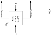
- Fig. 4 illustrates an expanded view of a masking functional block 306 of the arc fault detection system, such as in Fig. 3 , in accordance with an example embodiment of the present disclosure.
- a masking module receives data of a signal spectrum (e.g., A), such as generated using a Fourier Transform or Cosine Transform, for each signal segment within the predefined time period.
- the masking module receives a HF mask (e.g., B) and applies the HF mask to the signal spectrum to produce a HF filtered signal spectrum for the signal segment, and is referred to as Mask(HF).
- An example of the mask B is shown in Fig. 5 .
- the HF mask is used to generate a filtered signal spectrum of the signal segment having the frequency regions associated with power line communication.
- the masking module also applies an ARC mask (e.g., B), which is the inverse of the HF mask (e.g., B), to produce an ARC filtered signal spectrum for the signal segment, and is referred to as Mask(ARC).
- the ARC mask is used to generate a filtered signal spectrum of the signal segment without the frequency regions associated with power line communication .
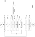
- Fig. 6 illustrates a flow diagram of an example process 600 implemented by one or more signal processing components of the arc fault detection system, such as in Fig. 1 , by which an arc fault signal is detected from high frequency signals monitored on a power line.
- the arc fault detection system partitions the monitored high frequency signal into a plurality of time-segmented signal segments, and evaluates each signal segment in order to detect for arc fault signals on the power line.
- the number N can equal a maximum number of signal segments for the high frequency signal within the predefined time period.
- the process 600 begins when power on the monitored power line is ON.
- the arc fault detection system waits for zero-crossing (ZX) interrupt.
- the arc fault detection system sets the counter (e.g., Step_Count) equal to 1.
- the arc fault detection system acquires a signal segment, which is a smaller interval of a high frequency signal that is monitored on the power line over a predefined time period (e.g., a half-cycle of a base frequency).
- the arc fault detection system processes the signal segment. For example, as described herein, each signal segment is processed by generating a signal spectrum, applying a mask to produce a filtered signal spectrum, determining a relative magnitude of energy of the filtered signal spectrum, comparing the relative magnitude to a spectrum energy threshold, and assigning a binary value based on the comparison to reflect a presence or absence of high frequency signal content of interest in the signal segment.
- the signal segment processing can be implemented to detect a presence of potential arc fault signal content and/or PLC signal content in a signal segment.
- the spectrum energy threshold for the ARC sub-process can be adjusted by the arc fault detection system based on a triggering event or other conditions (e.g., HF sub-process), such as for example described herein.
- the arc fault detection system increments the counter (e.g., Step_Count).
- the arc fault detection system compares the counter to a maximum number N. If the counter is less than N, then the process 600 returns to block 606 and acquires the next signal segment within the predefined time period, and implements the blocks 608, 610 and 612 in relations to the next signal segment. Otherwise, if the counter is equal to N, then the arc fault detection system determines an ARCing classification, e.g., a presence or absence of an arc fault signal in the monitored high frequency signal, based on the information accumulated from the signal segments of the monitored high frequency signal within the predefined time period.
- an ARCing classification e.g., a presence or absence of an arc fault signal in the monitored high frequency signal
- the determined classification is provided to an arc fault detection software within a circuit breaker (e.g. 100), which initiates a trip operation (e.g., TRIP) to interrupt power on the power line (e.g., 10) when an arc fault signal is detected.
- a trip operation e.g., TRIP
- Fig. 7 illustrates a flow diagram of an example process 700 implemented by one or more signal processing components of the arc fault detection system, such as in Fig. 1 , by which signal segment processing (e.g., 508), such as in the example process of Fig. 6 , is performed.
- the process 700 is an example implementation of the ARC sub-process and HF sub-process performed on each signal segment in a predefined time period.
- the process 700 begins at step 702, in which the arc fault detection system checks whether the counter (e.g., Step_Count) is equal to 1 for a predefined time period. If the counter is equal to 1, the prior accumulation value(s) 720, 738 (e.g., HF_ACC and SEG_ACC) for a prior time period is reset to zero. Otherwise, the process 700 proceeds to step 706 in which the arc fault detection system generates a signal spectrum for the signal segment to be processed.
- the signal spectrum can be computed using a Fourier Transform or a Cosine Transform or any suitable signal transform to determine a frequency spectrum of the RF signal segment.
- the HF sub-process is used to detect for PLC frequency signal component and other high frequency components of interest (e.g., steps 710, 712, 714, 716, 718 and 720), and the ARC sub-process is used to detect for potential arc frequency signal component (e.g., steps 730, 732, 734, 736, 738 and 740).
- the arc fault detection system retrieves a HF mask (e.g., B), and applies the HF mask to the signal spectrum A to produce a filtered signal spectrum.
- a HF mask e.g., B
- An example of the HF mask is shown in Fig. 5 .
- the HF filtered signal spectrum can be provided to an ACR to determine a maximum peak of the magnitude, which can instead be used as the relative magnitude.
- the relative magnitude is compared against a spectrum energy threshold (e.g., th h ) to determine a presence or absence of high frequency signal content in the HF filtered signal spectrum.
- the HF filtered signal spectrum is then converted to a binary value to reflect the presence or absence of high frequency signal content therein.
- the HF filtered signal spectrum can be assigned a binary value of "1" when the relative magnitude reflects the presence of high frequency signal content in the HF filtered signal spectrum, and can be assigned a binary value of "0" when the relative magnitude reflects the absence of high frequency signal content in the HF filtered signal spectrum, or vice-a-versa.
- the arc fault detection system can generate a binary word (e.g., BIN_WD1) reflecting a sequence of the binary values for each signal segment, and can also accumulate a number of times high frequency signal content is present or absent (e.g., HF_ACC) in the predefined time period.
- the binary word and accumulation value can then be used to adjust a spectrum energy threshold (e.g., th a ) to be used in future ARC sub-processing.
- the arc fault detection system retrieves an ARC mask (e.g., B which is the inverse of mask B), and applies the ARC mask to the signal spectrum A to produce a filtered signal spectrum.
- the ARC filtered signal spectrum can be provided to an ACR to determine a maximum peak of the magnitude, which can instead be used as the relative magnitude.
- the arc fault detection system can generate a binary word (e.g., BIN_WD2) reflecting a sequence of the binary values for each signal segment, and can also accumulate a number of times high frequency signal content is present or absent (e.g., SEG_ACC) within the predefined time period.
- the binary word and accumulation value can then be used to detect for a presence or absence of an arc fault signal in the high frequency signal monitored over the predefined time period.
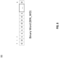
- Fig. 8 illustrates an example format of a binary word 800 generated for a high frequency signal, which is monitored over a predefined period of time, such as by the process of Fig. 7 , in accordance with an example embodiment of the present disclosure.
- N represents the number of signal segments of a high frequency signal monitored over a predefined time period.
- the binary word 800 is a sequence of binary values of N-partitioned signal segments of a monitored high frequency signal on a power line.
- the binary values in the binary word 800 can represent a presence or absence of high frequency signal content of interest (e.g., PLC or arc fault signal component) for the N-signal segments.
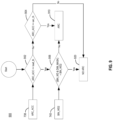
- Fig. 9 illustrates a flow diagram of an example process 900 implemented by one or more processing components of the arc fault detection system, such as in Fig. 1 , to classify a high frequency signal as containing an arc fault signal or non-arc fault signal, in accordance with an example embodiment of the present disclosure.
- a load threshold e.g., load_th
- an arc threshold e.g., arc_th
- the arc fault detection system compares the arc binary accumulation, e.g., SEG_ACC from the ARC sub-process, in which high frequency signal content was detected in the signal segments (e.g., step 738 of Fig. 7 ) to the load threshold. If the arc binary accumulation is greater than the load threshold, then at step 904 the arc fault detection system compares the arc binary accumulation to the arc threshold. If the arc binary accumulation is greater than or equal to the arc threshold, then the arc fault detection system detects a presence of an arc fault signal at step 910. Otherwise, if the arc binary accumulation is less than the arc threshold, then the arc fault detection system detects an absence of an arc fault signal at step 920.
- the arc binary accumulation e.g., SEG_ACC from the ARC sub-process
- the arc fault detection system compares the binary word, e.g., BIN_WD2, reflecting a presence or absence of high frequency signal content in the signal segments of the high frequency signal (e.g., step 740 of Fig. 7 ) to one or more predetermined binary word(s) or an event mask(s) (e.g., DIM_MASK reflecting a dimmer event).
- the predetermined binary words, or event masks represent patterns reflecting known arc fault events or non-arc fault events.
- the arc fault detection system detects a presence of an arc fault signal at step 910. Otherwise, if the binary word BIN_WD2 matches the predetermined binary words and/or masks representing non-arc fault events, then the arc fault detection system detects an absence of an arc fault signal at step 920.
- the above process 900 is simply provided as an example.
- Various predefined binary patterns either reflected in a predefined binary word or mask, representing a presence or absence of an arc fault event can also be evaluated at step 806 to determine an occurrence or not of an arc fault event.
- the predefined binary patterns can be determined from empirical data, and the arc fault detection system can be updated to add, modify or remove predetermined patterns, such as from a remote management device which can communicate with the arc fault detection system, such as in the circuit breaker of Fig. 1 .
- the load on the power line may inadvertently result in a detection of a potential (nuisance) arc fault signal in a signal segment, such as for example due to an operation of a dimmer.
- a potential (nuisance) arc fault signal in a signal segment
- the fast switch ON may appear as a pulse having a frequency response in a narrow high frequency range (e.g., MHz).
- a narrow high frequency range e.g., MHz
- this operation may be observed in the signal spectrum and may be classified as a potential arc fault signal component (e.g., classified with a binary value of "1").
- the load and arc thresholds and predetermined patterns can be configured accordingly, to avoid inadvertent arc fault detection due to non-arc fault events.
- the dimmer mask (DIM_MASK) which represents a non-arc fault event, can contain potential dimmer positions or some unique load switching.
- these known load events can be represented by a predetermined pattern, e.g., the location of certain binary values in certain locations in the binary word.
- the load and arc thresholds can, for example, be greater than 2, to taken into account the possibility that high frequency signal content in a signal segment may be due to known load events, such as a dimmer event.
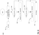
- Fig. 10 illustrates a flow diagram of an example process 1000 implemented by one or more processing components of the arc fault detection system, such as in Fig. 1 , by which a spectrum energy threshold (e.g., th a ), which is used in signal segment processing, such as the ARC sub-process, to detect for arc fault signal content, is adjusted in accordance with an example embodiment of the present disclosure.
- the arc fault detection system computes a moving average over a number of half-cycles (e.g., three or four half-cycles) and checks against a hysteresis threshold for adjustments of threshold th a , which will be used in the next half-cycle to determine binary classification for the arcing word.
- the process 1000 is described in greater detail below.
- the arc fault detection system computes a moving average of the accumulated number of times, e.g., HF_ACC 720, that high frequency signal content was detected in the HF filtered signal spectrum of the signal segments ( Fig. 7 ), over a number of predefined time periods (e.g., over 3 or 4 half-cycles).
- the computed moving average is greater than the spectrum energy threshold, e.g., th a , used in the ARC sub-process
- the arc fault detection system updates the spectrum energy threshold th a to be equal to a threshold plus noise level (TH + noise level) according to a threshold hysteresis curve, such as for example in Fig. 11 .
- the adjusted threshold th a can be used in future binary classification performed by the ARC sub-process, such as for example in the next predefined time period.
- the arc fault detection system compares the computed moving average to the spectrum energy threshold th h used in the HF detection sub-process. If the computed moving average is not less than the spectrum energy threshold th h , then no adjustment is made to the spectrum energy threshold th a at step 1012. Otherwise, if the computed moving average is less than the spectrum energy threshold th h , then the arc fault detection system updates the spectrum energy threshold th a to be equal to a threshold minus noise level (TH - noise level) at step 1006 according to a threshold hysteresis curve 1100, such as for example in Fig. 11 .
- the adjusted threshold th a can be used in future binary classification performed by the ARC sub-process, such as for example in the next predefined time period.
- the threshold th a can be a dynamic threshold, which can be dynamically adjusted to increase or decrease the sensitivity for detecting a presence of high frequency components (which may potentially correspond to an arc fault signal) according to noise on the power line system.
- the moving average of HF_ACC count e.g., the moving average could be 4 half-cycles to 8 half-cycles of a base frequency
- the moving average of the HF_ACC count is very high (e.g., above hf_th a ),there is a lot of high frequency energy in the network, and thus, the spectrum energy threshold th a is increased by some noise level to desensitize arc fault energy detection.
- the amount of noise level can be empirically determined. Otherwise, if the moving average of the HF_ACC count is very low (e.g., below hf_th h ), meaning there is very low, or no, power line carriers, then the sensitivity of the arc fault energy detection is increased in the detection system by reducing the spectrum energy threshold th a by a noise level.
- the noise level to add or subtract can be performed according to a predefined threshold hysteresis curve 1100, such as shown in Fig. 11 .
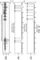
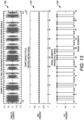
- Fig. 12 illustrates three graphs 1200, 1210 and 1220 reflecting an example snapshot of monitored high frequency signal over a half-cycle with the presence of PLC and ARCing signals based on experimental data.
- the predefined time period of the monitored high frequency signal is a half-cycle of a base frequency, and the high frequency signal is partitioned into N-signal segments. As shown in Fig.
- the first graph 1200 shows raw high frequency (HF) current of the monitored signal versus samples/half-cycle
- the second graph 1210 shows arc present (e.g., the presence of potential ARC high frequency signal content) versus signal segments in the half-cycle
- the third graph 1220 shows PLC present (e.g., the presence of PLC high frequency signal content) versus signal segment in the half-cycle.
- there are 10 instances in which potential ARC high frequency signal content was detected in the signal segments as shown in the graph 1210 and there are 9 instances in which potential PLC high frequency signal content was detected in the signal segments as shown in the graph 1220.
- the arc fault detection system would detect a presence of an arc fault signal, and thus, an arc fault event for the monitored half-cycle.
- Fig. 13 illustrates three graphs 1300, 1310, and 1320 reflecting an example snapshot of a monitored high frequency signal over a half-cycle based on experimental data.
- the predefined time period of the monitored high frequency signal is a half-cycle of a base frequency
- the high frequency signal is partitioned into N-signal segments.
- the first graph 1300 shows raw high frequency (HF) current of the monitored signal versus samples/half-cycle
- the second graph 1310 shows arc present (e.g., the presence of potential ARC high frequency signal content) versus signal segments in the half-cycle
- the third graph 1320 shows PLC present (e.g., the presence of PLC high frequency signal content) versus signal segment in the half-cycle.
- example embodiments may be implemented as a machine, process, or article of manufacture by using standard programming and/or engineering techniques to produce programming software, firmware, hardware or any combination thereof.
- Any resulting program(s), having computer-readable program code, may be embodied on one or more computer-usable media such as resident memory devices, smart cards or other removable memory devices, or transmitting devices, thereby making a computer program product or article of manufacture according to the embodiments.
- the terms "article of manufacture” and “computer program product” as used herein are intended to encompass a computer program that exists permanently or temporarily on any computer-usable medium or in any transmitting medium which transmits such a program.
- a processor(s) or controller(s) as described herein can be a processing system, which can include one or more processors, such as CPU, GPU, controller, FPGA (Field Programmable Gate Array), ASIC (Application-Specific Integrated Circuit) or other dedicated circuitry or other processing unit, which controls the operations of the devices or systems, described herein.
- Memory/storage devices can include, but are not limited to, disks, solid state drives, optical disks, removable memory devices such as smart cards, SIMs, WIMs, semiconductor memories such as RAM, ROM, PROMS, etc.
- Transmitting mediums or networks include, but are not limited to, transmission via wireless communication (e.g., Radio Frequency (RF) communication, Bluetooth ® , Wi-Fi, Li-Fi, etc.), the Internet, intranets, telephone/modem-based network communication, hardwired/cabled communication network, satellite communication, and other stationary or mobile network systems/communication links.
- wireless communication e.g., Radio Frequency (RF) communication, Bluetooth ® , Wi-Fi, Li-Fi, etc.
- RF Radio Frequency
- Bluetooth ® Wireless Fidelity
- Wi-Fi Wireless Fidelity
- Li-Fi Wireless Fidelity
- the detection features and functions can be implemented in a circuit breaker, or across separate component(s) or module(s), which can communicate and interact with a circuit breaker or other power interruption device to facilitate interruption of power (e.g., current or voltage) on a power line of a circuit when an arc fault is detected.
- the signal segment processing as described herein, can be implemented in the same processor or a separate processor (e.g., a separate ASIC or FPGA).
- the signal spectrum for the high frequency signal or segments thereof can be generated using a Fourier Transform (e.g., discrete Fourier Transform), Cosine Transform (e.g., discrete Cosine Transform), or other suitable mathematical transforms.
- the predefined time period can be a half-cycle of a base frequency, a full-cycle of a base frequency or any number of half-cycles.
Landscapes
- Physics & Mathematics (AREA)
- General Physics & Mathematics (AREA)
- Cable Transmission Systems, Equalization Of Radio And Reduction Of Echo (AREA)
- Emergency Protection Circuit Devices (AREA)
- Monitoring And Testing Of Transmission In General (AREA)
- Testing Of Short-Circuits, Discontinuities, Leakage, Or Incorrect Line Connections (AREA)
Claims (14)
- Verfahren zum Detektieren eines Lichtbogenfehlersignals aus einem Hochfrequenzsignal an einer Stromleitung, umfassend:Überwachen eines Hochfrequenzsignals an einer Stromleitung über einen ersten vordefinierten Zeitraum;Aufteilen des Hochfrequenzsignals in eine Vielzahl von zeitlich segmentierten Signalsegmenten, wobei jedes Signalsegment ein kleineres Zeitintervall des ersten vordefinierten Zeitraums ist;für jedes Signalsegment, Anwenden eines ersten Filters auf ein Signalspektrum des Signalsegments, um ein erstes gefiltertes Signalspektrum mit einem oder mehreren Frequenzintervallen zu erzeugen, die einer aus dem Signalspektrum gefilterter Stromleitungskommunikation zugeordnet sind, Prüfen auf Hochfrequenzsignalinhalt in dem ersten gefilterten Signalspektrum des Signalsegments und Zuweisen eines ersten Binärwerts zu dem Signalsegment basierend auf einem Vorhandensein oder Nichtvorhandensein von Hochfrequenzsignalinhalt in dem ersten gefilterten Signalspektrum;Bestimmen, ob das Hochfrequenzsignal ein Lichtbogenfehlersignal enthält, basierend auf den ersten Binärwerten der Vielzahl von Signalsegmenten in dem ersten vordefinierten Zeitraum; undBewirken, dass Leistung an der Stromleitung unterbrochen wird, wenn ein Lichtbogenfehlersignal bestimmt wird,wobei das Bestimmen, ob das Hochfrequenzsignal ein Lichtbogenfehlersignal enthält, umfasst:Zählen einer Anzahl von Malen, die Hochfrequenzsignalinhalt über den vordefinierten Zeitraum vorhanden ist, basierend auf den ersten Binärwerten;Vergleichen der Anzahl von Malen, die Hochfrequenzsignalinhalt über den vordefinierten Zeitraum vorhanden ist, mit mindestens einem ersten Hochfrequenzschwellenwert; undDetektieren eines Lichtbogenfehlersignals, wenn eine Bedingung für den ersten Hochfrequenzschwellenwert erfüllt ist,wobei das Verfahren ferner umfasst:
Erzeugen eines Binärworts aus einer Sequenz der ersten Binärwerte für die Signalsegmente aus dem ersten vordefinierten Zeitraum,wobei das Bestimmen ferner umfasst:
wenn die Bedingung für den ersten Hochfrequenzschwellenwert nicht erfüllt ist, Auswerten des Binärworts, um ein Auftreten eines Lichtbogenfehlersignals zu detektieren. - Verfahren nach Anspruch 1, wobei für jedes Signalsegment das Zuweisen eines ersten Binärwerts umfasst:Bestimmen einer relativen Energiegröße des ersten gefilterten Signalspektrums des Signalsegments;Vergleichen der relativen Energiegröße mit einem ersten Spektrumenergieschwellenwert zum Bestimmen eines Vorhandenseins oder Nichtvorhandenseins von Hochfrequenzsignalinhalt in dem Signalsegment; undZuweisen des ersten Binärwerts zu dem Signalsegment basierend auf dem Vergleich.
- Verfahren nach Anspruch 2, ferner umfassend:für jedes Signalsegment, Anwenden eines zweiten Filters, das ein inverses Filter des ersten Filters ist, auf ein Signalspektrum des Signalsegments, um ein zweites gefiltertes Signalspektrum mit einem oder mehreren Frequenzintervallen zu erzeugen, die einer Stromleitungskommunikation zugeordnet sind, Prüfen auf Hochfrequenzsignalinhalt in dem zweiten gefilterten Signalspektrum des Signalsegments und Zuweisen eines zweiten Binärwerts zu dem Signalsegment basierend auf einem Vorhandensein oder Nichtvorhandensein von Hochfrequenzsignalinhalt in dem zweiten gefilterten Signalspektrum des Signalsegments; undAnpassen des ersten Spektrumenergieschwellenwerts basierend auf den zweiten Binärwerten der Vielzahl von Signalsegmenten in dem ersten Zeitraum,wobei der angepasste erste Spektrumenergieschwellenwert verwendet wird, um Hochfrequenzsignal an der Stromleitung in einem Zeitraum nach dem ersten vordefinierten Zeitraum auszuwerten.
- Verfahren nach Anspruch 3, wobei für jedes Signalsegment das Zuweisen eines zweiten Binärwerts umfasst:Bestimmen einer relativen Energiegröße des zweiten gefilterten Signalspektrums des Signalsegments;Vergleichen der relativen Energiegröße des zweiten gefilterten Signalspektrums mit einem zweiten Spektrumenergieschwellenwert zum Bestimmen eines Vorhandenseins oder Nichtvorhandenseins von Hochfrequenzsignalinhalt in dem Signalsegment; undZuweisen des zweiten Binärwerts zu dem Signalsegment basierend auf dem Vergleich.
- Verfahren nach Anspruch 1, wobei der erste Hochfrequenzschwellenwert einer Last an der Stromleitung zugeordnet ist und ein zweiter Hochfrequenzschwellenwert einer Lichtbogenbildung an der Stromleitung zugeordnet ist, wobei das Bestimmen, ob das Hochfrequenzsignal ein Lichtbogenfehlersignal enthält, ferner umfasst:wenn der erste Hochfrequenzschwellenwert erfüllt ist, Vergleichen der Anzahl von Malen, die Hochfrequenzsignalinhalt über den vordefinierten Zeitraum vorhanden ist, mit dem zweiten Hochfrequenzschwellenwert,wobei ein Lichtbogenfehlersignal detektiert wird, wenn beide Bedingungen für den ersten und den zweiten Hochfrequenzschwellenwert erfüllt sind.
- Verfahren nach Anspruch 1, wobei das Auswerten umfasst:
Vergleichen des Binärworts mit einem oder mehreren vordefinierten Wortmustern, um ein Auftreten oder Nichtauftreten eines Lichtbogenfehlersignals in dem Hochfrequenzsignal zu detektieren, wobei das eine oder die mehreren vordefinierten Wortmuster ein vordefiniertes Lichtbogenfehlerereignis oder Nichtlichtbogenfehlerereignis widerspiegeln. - Verfahren nach Anspruch 1, wobei der vordefinierte Zeitraum ein Halbzyklus einer Grundfrequenz ist, das Signalspektrum für jedes Signalsegment unter Verwendung einer Fourier-Transformation oder einer Cosinus-Transformation erzeugt wird und die Überwachungs-, Aufteilungs-, Anwendungs-, Prüfungs-, Zuweisungs- und Bestimmungsoperationen in einem Schutzschalter durchgeführt werden.
- Lichtbogenfehlerdetektionsvorrichtung zum Detektieren eines Lichtbogenfehlersignals aus einem Hochfrequenzsignal an einer Stromleitung, umfassend:einen Speicher; undeinen oder mehrere Prozessoren (212), die konfiguriert sind zum:Überwachen eines Hochfrequenzsignals an einer Stromleitung über einen ersten vordefinierten Zeitraum,Aufteilen des Hochfrequenzsignals in eine Vielzahl von zeitlich segmentierten Signalsegmenten, wobei jedes Signalsegment ein kleineres Zeitintervall des ersten vordefinierten Zeitraums ist,für jedes Signalsegment, Anwenden eines ersten Filters auf ein Signalspektrum des Signalsegments, um ein erstes gefiltertes Signalspektrum mit einem oder mehreren Frequenzintervallen zu erzeugen, die einer aus dem Signalspektrum gefilterter Stromleitungskommunikation zugeordnet sind, Prüfen auf Hochfrequenzsignalinhalt in dem ersten gefilterten Signalspektrum des Signalsegments und Zuweisen eines ersten Binärwerts zu dem Signalsegment basierend auf einem Vorhandensein oder Nichtvorhandensein von Hochfrequenzsignalinhalt in dem ersten gefilterten Signalspektrum,Bestimmen, ob das Hochfrequenzsignal ein Lichtbogenfehlersignal enthält, basierend auf den ersten Binärwerten der Vielzahl von Signalsegmenten in dem ersten vordefinierten Zeitraum, undBewirken, dass Leistung an der Stromleitung unterbrochen wird, wenn ein Lichtbogenfehlersignal bestimmt wird,wobei, um zu bestimmen, ob das Hochfrequenzsignal ein Lichtbogenfehlersignal enthält, der eine oder die mehreren Prozessoren (212) konfiguriert sind zum:Zählen einer Anzahl von Malen, die ein Hochfrequenzsignalinhalt über den vordefinierten Zeitraum vorhanden ist, basierend auf den ersten Binärwerten;Vergleichen der Anzahl von Malen, die ein Hochfrequenzsignalinhalt über den vordefinierten Zeitraum vorhanden ist, mit mindestens einem ersten Hochfrequenzschwellenwert; undErkennen eines Lichtbogenfehlersignals, wenn der erste Hochfrequenzschwellenwert erfüllt ist,wobei der eine oder die mehreren Prozessoren (212) ferner konfiguriert sind zum:Erzeugen eines Binärworts aus einer Sequenz der ersten Binärwerte für die Signalsegmente aus dem ersten vordefinierten Zeitraum,wobei, um zu bestimmen, ob das Hochfrequenzsignal ein Lichtbogenfehlersignal umfasst, der eine oder die mehreren Prozessoren (212) ferner konfiguriert sind zum:
wenn die Bedingung für den ersten Hochfrequenzschwellenwert nicht erfüllt ist, Auswerten des Binärworts, um ein Auftreten eines Lichtbogenfehlersignals zu erkennen. - Lichtbogenfehlererkennungsvorrichtung nach Anspruch 8, wobei für jedes Signalsegment, um einen Binärwert zuzuweisen, der eine oder die mehreren Prozessoren (212) konfiguriert sind zum:Bestimmen einer relativen Energiegröße des ersten gefilterten Signalspektrums des Signalsegments;Vergleichen der relativen Energiegröße mit einem ersten Spektrumenergieschwellenwert zum Bestimmen eines Vorhandenseins oder Nichtvorhandenseins eines Hochfrequenzsignalinhalts in dem Signalsegment; undZuweisen des ersten Binärwerts zu dem Signalsegment basierend auf dem Vergleich.
- Lichtbogenfehlererkennungsvorrichtung nach Anspruch 9, wobei der eine oder die mehreren Prozessoren (212) ferner konfiguriert sind zum:für jedes Signalsegment, Anwenden eines zweiten Filters, das ein inverses Filter des ersten Filters ist, auf ein Signalspektrum des Signalsegments, um ein zweites gefiltertes Signalspektrum mit einem oder mehreren Frequenzintervallen zu erzeugen, die einer Stromleitungskommunikation zugeordnet sind, Prüfen auf einen Hochfrequenzsignalinhalt in dem zweiten gefilterten Signalspektrum des Signalsegments und Zuweisen eines zweiten Binärwerts zu dem Signalsegment basierend auf einem Vorhandensein oder Nichtvorhandensein eines Hochfrequenzsignalinhalts in dem zweiten gefilterten Signalspektrum des Signalsegments; undAnpassen des ersten Spektrumenergieschwellenwerts basierend auf den zweiten Binärwerten der Vielzahl von Signalsegmenten in dem ersten Zeitraum,wobei der angepasste erste Spektrumenergieschwellenwert verwendet wird, um ein Hochfrequenzsignal an der Stromleitung in einem Zeitraum nach dem ersten vordefinierten Zeitraum auszuwerten.
- Lichtbogenfehlererkennungsvorrichtung nach Anspruch 10, wobei, für jedes Signalsegment, um einen zweiten Binärwert zuzuweisen, der eine oder die mehreren Prozessoren (212) konfiguriert sind zum:Bestimmen einer relativen Energiegröße des zweiten gefilterten Signalspektrums des Signalsegments;Vergleichen der relativen Energiegröße des zweiten gefilterten Signalspektrums mit einem zweiten Spektrumenergieschwellenwert zum Bestimmen eines Vorhandenseins oder Nichtvorhandenseins eines Hochfrequenzsignalinhalts in dem Signalsegment; undZuweisen des zweiten Binärwerts zu dem Signalsegment basierend auf dem Vergleich.
- Lichtbogenfehlererkennungsvorrichtung nach Anspruch 8, wobei der erste Hochfrequenzschwellenwert einer Last an der Stromleitung zugeordnet ist und ein zweiter Hochfrequenzschwellenwert einer Lichtbogenbildung an der Stromleitung zugeordnet ist,
wobei zum Bestimmen, ob das Hochfrequenzsignal ein Lichtbogenfehlersignal umfasst, der eine oder die mehreren Prozessoren (212) ferner konfiguriert sind zum:wenn der erste Hochfrequenzschwellenwert erfüllt ist, Vergleichen der Anzahl von Malen, die ein Hochfrequenzsignalinhalt über den vordefinierten Zeitraum vorhanden ist, mit dem zweiten Hochfrequenzschwellenwert,wobei der eine oder die mehreren Prozessoren (212) ein Lichtbogenfehlersignal erkennen, wenn beide Bedingungen für den ersten und den zweiten Hochfrequenzschwellenwert erfüllt sind. - Lichtbogenfehlererkennungsvorrichtung nach Anspruch 8, wobei, um das Binärwort auszuwerten, der eine oder die mehreren Prozessoren (212) konfiguriert sind zum:
Vergleichen des Binärworts mit einem oder mehreren vordefinierten Wortmustern, um ein Auftreten oder Nichtauftreten eines Lichtbogenfehlersignals in dem Hochfrequenzsignal zu erkennen, wobei das eine oder die mehreren vordefinierten Wortmuster ein vordefiniertes Lichtbogenfehlerereignis oder Nichtlichtbogenfehlerereignis widerspiegeln. - Materielles Computermedium, das computerausführbaren Code speichert, der, wenn er ausgeführt wird, konfiguriert ist, um ein Verfahren zum Erkennen eines Lichtbogenfehlersignals aus einem Hochfrequenzsignal an einer Stromleitung zu implementieren, wobei das Verfahren Folgendes umfasst:Überwachen eines Hochfrequenzsignals an einer Stromleitung über einen ersten vordefinierten Zeitraum;Partitionieren des Hochfrequenzsignals in eine Vielzahl von zeitsegmentierten Signalsegmenten, wobei jedes Signalsegment ein kleineres Zeitintervall des ersten vordefinierten Zeitraums ist;für jedes Signalsegment, Anwenden eines ersten Filters auf ein Signalspektrum des Signalsegments, um ein erstes gefiltertes Signalspektrum mit einem oder mehreren Frequenzintervallen zu erzeugen, die einer Stromleitungskommunikation zugeordnet sind, die aus dem Signalspektrum gefiltert ist, Prüfen auf einen Hochfrequenzsignalinhalt in dem ersten gefilterten Signalspektrum des Signalsegments und Zuweisen eines ersten Binärwerts zu dem Signalsegment basierend auf einem Vorhandensein oder Nichtvorhandensein eines Hochfrequenzsignalinhalts in dem ersten gefilterten Signalspektrum;Bestimmen, ob das Hochfrequenzsignal ein Lichtbogenfehlersignal umfasst, basierend auf den ersten Binärwerten der Vielzahl von Signalsegmenten in dem ersten vordefinierten Zeitraum; undBewirken, dass die Leistung an der Stromleitung unterbrochen wird, wenn ein Lichtbogenfehlersignal bestimmt wird,wobei das Bestimmen, ob das Hochfrequenzsignal ein Lichtbogenfehlersignal umfasst, Folgendes umfasst:Zählen einer Anzahl von Malen, die ein Hochfrequenzsignalinhalt über den vordefinierten Zeitraum vorhanden ist, basierend auf den ersten Binärwerten;Vergleichen der Anzahl von Malen, die ein Hochfrequenzsignalinhalt über den vordefinierten Zeitraum vorhanden ist, mit mindestens einem ersten Hochfrequenzschwellenwert; undErkennen eines Lichtbogenfehlersignals, wenn eine Bedingung für den ersten Hochfrequenzschwellenwert erfüllt ist,
wobei das Verfahren ferner Folgendes umfasst:Erzeugen eines Binärworts aus einer Sequenz der ersten Binärwerte für die Signalsegmente aus dem ersten vordefinierten Zeitraum,wobei das Bestimmen ferner Folgendes umfasst:
wenn die Bedingung für den ersten Hochfrequenzschwellenwert nicht erfüllt ist, Auswerten des Binärworts, um ein Auftreten eines Lichtbogenfehlersignals zu erkennen.
Applications Claiming Priority (2)
| Application Number | Priority Date | Filing Date | Title |
|---|---|---|---|
| US15/972,857 US10914779B2 (en) | 2018-05-07 | 2018-05-07 | Arc fault detection using time segmented captures |
| PCT/US2019/031008 WO2019217349A1 (en) | 2018-05-07 | 2019-05-07 | Improved arc fault detection using time segmented captures |
Publications (4)
| Publication Number | Publication Date |
|---|---|
| EP3782251A1 EP3782251A1 (de) | 2021-02-24 |
| EP3782251A4 EP3782251A4 (de) | 2022-01-12 |
| EP3782251B1 true EP3782251B1 (de) | 2025-07-02 |
| EP3782251C0 EP3782251C0 (de) | 2025-07-02 |
Family
ID=68384776
Family Applications (1)
| Application Number | Title | Priority Date | Filing Date |
|---|---|---|---|
| EP19800515.9A Active EP3782251B1 (de) | 2018-05-07 | 2019-05-07 | Verbesserte lichtbogenfehlerdetektion mittels zeitsegmentierter erfassung |
Country Status (4)
| Country | Link |
|---|---|
| US (1) | US10914779B2 (de) |
| EP (1) | EP3782251B1 (de) |
| CN (1) | CN112088475B (de) |
| WO (1) | WO2019217349A1 (de) |
Families Citing this family (16)
| Publication number | Priority date | Publication date | Assignee | Title |
|---|---|---|---|---|
| WO2015153503A2 (en) * | 2014-03-31 | 2015-10-08 | Hubbell Incorporated | Systems and methods for detecting and identifying arcing based on numerical analysis |
| US11041915B2 (en) * | 2018-09-18 | 2021-06-22 | Sentient Technology Holdings, LLC | Disturbance detecting current sensor |
| US11552465B2 (en) * | 2019-11-19 | 2023-01-10 | Itron, Inc. | Detecting electrical arcing in household electrical wiring |
| GB2597444B (en) | 2020-07-21 | 2024-06-26 | Eaton Intelligent Power Ltd | Arc fault detection device |
| CN112731087B (zh) * | 2021-01-20 | 2022-07-22 | 丰郅(上海)新能源科技有限公司 | 用于光伏领域的故障电弧检测系统及检测方法 |
| WO2022239411A1 (ja) * | 2021-05-11 | 2022-11-17 | 株式会社カネカ | 放電対応システム |
| US12212130B2 (en) * | 2021-08-12 | 2025-01-28 | Astronics Advanced Electronic Systems Corp. | System and method for detection and isolation of arc fault |
| US12348024B2 (en) | 2022-02-07 | 2025-07-01 | Hubbell Incorporated | Arc fault detection through mixed-signal machine learning and neural networks |
| CN114740076B (zh) * | 2022-03-16 | 2025-09-23 | 上海润达榕嘉生物科技有限公司 | 对三重四极杆质谱仪系统信号的滤波处理方法 |
| US11902757B2 (en) * | 2022-06-14 | 2024-02-13 | Tencent America LLC | Techniques for unified acoustic echo suppression using a recurrent neural network |
| CN114696742B (zh) * | 2022-06-01 | 2022-09-13 | 阳光电源股份有限公司 | 光伏系统直流电弧故障检测方法、装置、设备及介质 |
| US12394970B2 (en) * | 2022-12-29 | 2025-08-19 | Schneider Electric USA, Inc. | Detecting power line carrier presence in a branch circuit and improving AF detection and nuisance tripping in CAFI/DF breaker |
| WO2024165116A2 (en) * | 2023-02-10 | 2024-08-15 | Eaton Intelligent Power Limited | Method, evaluation module and detection system for detecting electric series arcs or glowing contacts by use of a time course of a relevant current |
| DE102023208612A1 (de) * | 2023-09-06 | 2025-03-06 | Robert Bosch Gesellschaft mit beschränkter Haftung | Verfahren zum fehlertoleranten Betrieb einer Verarbeitungseinheit und einer Ver-arbeitungsanordnung, Schaltungsanordnung und Recheneinheit |
| CN117892067B (zh) * | 2024-03-15 | 2024-05-28 | 国网上海市电力公司 | 一种低频电流局放监测抗干扰方法、装置、设备及介质 |
| CN120801959B (zh) * | 2025-09-09 | 2025-11-25 | 深圳供电局有限公司 | 电弧故障检测方法及相关装置 |
Family Cites Families (21)
| Publication number | Priority date | Publication date | Assignee | Title |
|---|---|---|---|---|
| US4466071A (en) | 1981-09-28 | 1984-08-14 | Texas A&M University System | High impedance fault detection apparatus and method |
| US5963406A (en) * | 1997-12-19 | 1999-10-05 | Leviton Manufacturing Co., Inc. | Arc fault detector with circuit interrupter |
| IL135120A0 (en) * | 2000-03-16 | 2001-05-20 | Sapir Michael | Apparatus for the detection and early warning of electrical arcing fault |
| US7345860B2 (en) * | 2001-10-17 | 2008-03-18 | Square D Company | Load recognition and series arc detection using load current/line voltage normalization algorithms |
| US7151656B2 (en) * | 2001-10-17 | 2006-12-19 | Square D Company | Arc fault circuit interrupter system |
| US6980407B2 (en) * | 2002-12-09 | 2005-12-27 | Texas Instrument Incorporated | Arc detection apparatus and method |
| US7062388B2 (en) | 2004-03-18 | 2006-06-13 | General Electric Company | Series arc detection |
| US7190562B2 (en) * | 2004-09-09 | 2007-03-13 | Sensata Technologies, Inc. | Method for detecting arc faults |
| US7492163B2 (en) | 2006-04-27 | 2009-02-17 | Siemens Energy & Automation, Inc. | Systems, devices, and methods for arc fault detection |
| US7864492B2 (en) | 2006-10-31 | 2011-01-04 | Siemens Industry, Inc. | Systems and methods for arc fault detection |
| CN101706527B (zh) * | 2009-10-30 | 2012-01-04 | 西安交通大学 | 基于电流高频分量时频特征的电弧故障检测方法 |
| US8929036B2 (en) | 2010-04-08 | 2015-01-06 | Siemens Industry, Inc. | Arc fault circuit detection methods, systems, and apparatus including delay |
| US8373570B2 (en) * | 2010-10-26 | 2013-02-12 | Cooper Technologies Company | ARC fault detection method and apparatus |
| US8576521B2 (en) * | 2011-08-16 | 2013-11-05 | Schneider Electric USA, Inc. | Adaptive light detection for arc mitigation systems |
| US9696363B2 (en) | 2012-09-25 | 2017-07-04 | Stmicroelectronics S.R.L. | System and method for an arc fault detector |
| EP2806518B1 (de) * | 2013-05-24 | 2021-01-27 | Delta Electronics (Thailand) Public Co., Ltd. | Detektion serieller Lichtbögen basierend auf den harmonischen Anteilen im DC Stromsignal |
| EP2887082B1 (de) * | 2013-12-23 | 2019-09-18 | Sensata Technologies, Inc. | Verbesserte Rauschübertragungsimmunität einer mehrstrangigen Lichtbogenfehlerdetektionsvorrichtung |
| JP6464836B2 (ja) * | 2015-03-09 | 2019-02-06 | オムロン株式会社 | アーク検出装置およびアーク検出方法 |
| CN105093082A (zh) * | 2015-08-31 | 2015-11-25 | 上海正泰电源系统有限公司 | 一种直流故障电弧检测方法 |
| CN106026053A (zh) * | 2016-08-02 | 2016-10-12 | 辽宁拓新电力电子有限公司 | 基于低励磁阻抗变压器单相接地故障定位隔离系统和方法 |
| CN107294494A (zh) * | 2017-07-03 | 2017-10-24 | 上海岩芯电子科技有限公司 | 光伏系统直流侧电弧故障检测装置及其检测方法 |
-
2018
- 2018-05-07 US US15/972,857 patent/US10914779B2/en active Active
-
2019
- 2019-05-07 EP EP19800515.9A patent/EP3782251B1/de active Active
- 2019-05-07 CN CN201980030771.6A patent/CN112088475B/zh active Active
- 2019-05-07 WO PCT/US2019/031008 patent/WO2019217349A1/en not_active Ceased
Also Published As
| Publication number | Publication date |
|---|---|
| WO2019217349A1 (en) | 2019-11-14 |
| US10914779B2 (en) | 2021-02-09 |
| CN112088475B (zh) | 2023-05-12 |
| EP3782251A4 (de) | 2022-01-12 |
| EP3782251A1 (de) | 2021-02-24 |
| US20190339319A1 (en) | 2019-11-07 |
| EP3782251C0 (de) | 2025-07-02 |
| CN112088475A (zh) | 2020-12-15 |
Similar Documents
| Publication | Publication Date | Title |
|---|---|---|
| EP3782251B1 (de) | Verbesserte lichtbogenfehlerdetektion mittels zeitsegmentierter erfassung | |
| US11165237B2 (en) | Arc fault detection using frequency hopping techniques | |
| TWI474690B (zh) | 偵測無線麥克風訊號的無線電感測器及其方法 | |
| US7133686B2 (en) | System and method for identifying interferes in a communication spectrum | |
| CN101414847B (zh) | 干扰检测器及干扰检测方法 | |
| US9939481B2 (en) | System and method for an arc fault detector | |
| WO2012099943A1 (en) | Interference detection in a powerline communication network | |
| US20070202829A1 (en) | Receiver for Narrowband Interference Cancellation | |
| EP2660620B1 (de) | Vorrichtung zur Warnung vor Radarfallen | |
| US20170163455A1 (en) | Detection of simultaneous double transmission | |
| US12394970B2 (en) | Detecting power line carrier presence in a branch circuit and improving AF detection and nuisance tripping in CAFI/DF breaker | |
| CN114521237A (zh) | 局部放电的检测 | |
| KR101298434B1 (ko) | 무선 통신 시스템의 스펙트럼 점유를 검출하는 스펙트럼검출 장치 및 스펙트럼 검출 방법 | |
| CN106470021B (zh) | 增益控制设备 | |
| Poluektov et al. | Sensitivity analysis of a PLC-based anti-islanding solution using DSSS | |
| CN112237022B (zh) | 执行环境射频监视 | |
| Hosseini et al. | Enhanced FCME thresholding for wavelet‐based cognitive UWB over fading channels | |
| CN114244454B (zh) | 通信干扰检测方法及装置 | |
| US7173800B2 (en) | Time-optimum reception of protection commands in a remote tripping device | |
| JP2017500539A (ja) | 無線ネットワークにおける狭帯域干渉を検出する方法 | |
| Bhatt et al. | Non-uniform spectrum sensing using computationally efficient 2-level (FFT-Goertzel) based Energy Detection | |
| Marigodov | Improvement of noise stability of multi-channel communication systems with repetition |
Legal Events
| Date | Code | Title | Description |
|---|---|---|---|
| STAA | Information on the status of an ep patent application or granted ep patent |
Free format text: STATUS: THE INTERNATIONAL PUBLICATION HAS BEEN MADE |
|
| PUAI | Public reference made under article 153(3) epc to a published international application that has entered the european phase |
Free format text: ORIGINAL CODE: 0009012 |
|
| STAA | Information on the status of an ep patent application or granted ep patent |
Free format text: STATUS: REQUEST FOR EXAMINATION WAS MADE |
|
| 17P | Request for examination filed |
Effective date: 20201117 |
|
| AK | Designated contracting states |
Kind code of ref document: A1 Designated state(s): AL AT BE BG CH CY CZ DE DK EE ES FI FR GB GR HR HU IE IS IT LI LT LU LV MC MK MT NL NO PL PT RO RS SE SI SK SM TR |
|
| AX | Request for extension of the european patent |
Extension state: BA ME |
|
| RIN1 | Information on inventor provided before grant (corrected) |
Inventor name: JAKUPI, ANDI |
|
| DAV | Request for validation of the european patent (deleted) | ||
| DAX | Request for extension of the european patent (deleted) | ||
| REG | Reference to a national code |
Ref country code: DE Ref legal event code: R079 Free format text: PREVIOUS MAIN CLASS: H02H0001000000 Ipc: G01R0031120000 Ref document number: 602019071996 Country of ref document: DE |
|
| A4 | Supplementary search report drawn up and despatched |
Effective date: 20211213 |
|
| RIC1 | Information provided on ipc code assigned before grant |
Ipc: G01R 31/12 20200101AFI20211207BHEP |
|
| STAA | Information on the status of an ep patent application or granted ep patent |
Free format text: STATUS: EXAMINATION IS IN PROGRESS |
|
| 17Q | First examination report despatched |
Effective date: 20230927 |
|
| GRAP | Despatch of communication of intention to grant a patent |
Free format text: ORIGINAL CODE: EPIDOSNIGR1 |
|
| STAA | Information on the status of an ep patent application or granted ep patent |
Free format text: STATUS: GRANT OF PATENT IS INTENDED |
|
| INTG | Intention to grant announced |
Effective date: 20250214 |
|
| GRAS | Grant fee paid |
Free format text: ORIGINAL CODE: EPIDOSNIGR3 |
|
| GRAA | (expected) grant |
Free format text: ORIGINAL CODE: 0009210 |
|
| STAA | Information on the status of an ep patent application or granted ep patent |
Free format text: STATUS: THE PATENT HAS BEEN GRANTED |
|
| AK | Designated contracting states |
Kind code of ref document: B1 Designated state(s): AL AT BE BG CH CY CZ DE DK EE ES FI FR GB GR HR HU IE IS IT LI LT LU LV MC MK MT NL NO PL PT RO RS SE SI SK SM TR |
|
| REG | Reference to a national code |
Ref country code: GB Ref legal event code: FG4D |
|
| REG | Reference to a national code |
Ref country code: CH Ref legal event code: EP |
|
| REG | Reference to a national code |
Ref country code: IE Ref legal event code: FG4D |
|
| U01 | Request for unitary effect filed |
Effective date: 20250702 |
|
| U07 | Unitary effect registered |
Designated state(s): AT BE BG DE DK EE FI FR IT LT LU LV MT NL PT RO SE SI Effective date: 20250708 |
|
| PG25 | Lapsed in a contracting state [announced via postgrant information from national office to epo] |
Ref country code: IS Free format text: LAPSE BECAUSE OF FAILURE TO SUBMIT A TRANSLATION OF THE DESCRIPTION OR TO PAY THE FEE WITHIN THE PRESCRIBED TIME-LIMIT Effective date: 20251102 |
|
| PG25 | Lapsed in a contracting state [announced via postgrant information from national office to epo] |
Ref country code: NO Free format text: LAPSE BECAUSE OF FAILURE TO SUBMIT A TRANSLATION OF THE DESCRIPTION OR TO PAY THE FEE WITHIN THE PRESCRIBED TIME-LIMIT Effective date: 20251002 |
|
| PG25 | Lapsed in a contracting state [announced via postgrant information from national office to epo] |
Ref country code: HR Free format text: LAPSE BECAUSE OF FAILURE TO SUBMIT A TRANSLATION OF THE DESCRIPTION OR TO PAY THE FEE WITHIN THE PRESCRIBED TIME-LIMIT Effective date: 20250702 |
|
| PG25 | Lapsed in a contracting state [announced via postgrant information from national office to epo] |
Ref country code: GR Free format text: LAPSE BECAUSE OF FAILURE TO SUBMIT A TRANSLATION OF THE DESCRIPTION OR TO PAY THE FEE WITHIN THE PRESCRIBED TIME-LIMIT Effective date: 20251003 |
|
| PG25 | Lapsed in a contracting state [announced via postgrant information from national office to epo] |
Ref country code: CZ Free format text: LAPSE BECAUSE OF FAILURE TO SUBMIT A TRANSLATION OF THE DESCRIPTION OR TO PAY THE FEE WITHIN THE PRESCRIBED TIME-LIMIT Effective date: 20250702 |
|
| PG25 | Lapsed in a contracting state [announced via postgrant information from national office to epo] |
Ref country code: PL Free format text: LAPSE BECAUSE OF FAILURE TO SUBMIT A TRANSLATION OF THE DESCRIPTION OR TO PAY THE FEE WITHIN THE PRESCRIBED TIME-LIMIT Effective date: 20250702 |
|
| PG25 | Lapsed in a contracting state [announced via postgrant information from national office to epo] |
Ref country code: RS Free format text: LAPSE BECAUSE OF FAILURE TO SUBMIT A TRANSLATION OF THE DESCRIPTION OR TO PAY THE FEE WITHIN THE PRESCRIBED TIME-LIMIT Effective date: 20251002 |
|
| PG25 | Lapsed in a contracting state [announced via postgrant information from national office to epo] |
Ref country code: ES Free format text: LAPSE BECAUSE OF FAILURE TO SUBMIT A TRANSLATION OF THE DESCRIPTION OR TO PAY THE FEE WITHIN THE PRESCRIBED TIME-LIMIT Effective date: 20250702 |
|
| PG25 | Lapsed in a contracting state [announced via postgrant information from national office to epo] |
Ref country code: SM Free format text: LAPSE BECAUSE OF FAILURE TO SUBMIT A TRANSLATION OF THE DESCRIPTION OR TO PAY THE FEE WITHIN THE PRESCRIBED TIME-LIMIT Effective date: 20250702 |
|
| PG25 | Lapsed in a contracting state [announced via postgrant information from national office to epo] |
Ref country code: SK Free format text: LAPSE BECAUSE OF FAILURE TO SUBMIT A TRANSLATION OF THE DESCRIPTION OR TO PAY THE FEE WITHIN THE PRESCRIBED TIME-LIMIT Effective date: 20250702 |