EP3782304B1 - Unité radio distante et unité centrale pour station émettrice-réceptrice de base - Google Patents
Unité radio distante et unité centrale pour station émettrice-réceptrice de base Download PDFInfo
- Publication number
- EP3782304B1 EP3782304B1 EP18728841.0A EP18728841A EP3782304B1 EP 3782304 B1 EP3782304 B1 EP 3782304B1 EP 18728841 A EP18728841 A EP 18728841A EP 3782304 B1 EP3782304 B1 EP 3782304B1
- Authority
- EP
- European Patent Office
- Prior art keywords
- remote radio
- unit
- signal
- radio unit
- base transceiver
- Prior art date
- Legal status (The legal status is an assumption and is not a legal conclusion. Google has not performed a legal analysis and makes no representation as to the accuracy of the status listed.)
- Active
Links
Images







Classifications
-
- H—ELECTRICITY
- H04—ELECTRIC COMMUNICATION TECHNIQUE
- H04B—TRANSMISSION
- H04B10/00—Transmission systems employing electromagnetic waves other than radio-waves, e.g. infrared, visible or ultraviolet light, or employing corpuscular radiation, e.g. quantum communication
- H04B10/25—Arrangements specific to fibre transmission
- H04B10/2575—Radio-over-fibre, e.g. radio frequency signal modulated onto an optical carrier
-
- H—ELECTRICITY
- H04—ELECTRIC COMMUNICATION TECHNIQUE
- H04B—TRANSMISSION
- H04B10/00—Transmission systems employing electromagnetic waves other than radio-waves, e.g. infrared, visible or ultraviolet light, or employing corpuscular radiation, e.g. quantum communication
- H04B10/40—Transceivers
-
- H—ELECTRICITY
- H04—ELECTRIC COMMUNICATION TECHNIQUE
- H04B—TRANSMISSION
- H04B10/00—Transmission systems employing electromagnetic waves other than radio-waves, e.g. infrared, visible or ultraviolet light, or employing corpuscular radiation, e.g. quantum communication
- H04B10/50—Transmitters
- H04B10/58—Compensation for non-linear transmitter output
-
- H—ELECTRICITY
- H04—ELECTRIC COMMUNICATION TECHNIQUE
- H04W—WIRELESS COMMUNICATION NETWORKS
- H04W88/00—Devices specially adapted for wireless communication networks, e.g. terminals, base stations or access point devices
- H04W88/08—Access point devices
- H04W88/085—Access point devices with remote components
Definitions
- the present disclosure relates to the field of wireless communications. More specifically, the present disclosure relates to a remote radio unit and a central unit of a base transceiver station coupled by a radio-over-fiber link as well as corresponding methods.
- Radio over fiber (RoF) system the radio signal is used for modulating the intensity of an optical carrier.
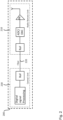
- Figure 1 shows a simplified diagram of a conventional RoF link or system, i.e. base transceiver station 100, where the radio signal is converted into an optical signal by the RoF transceiver of the central unit 130 comprising an electronic-to-optical (EO) converter.
- EO electronic-to-optical
- the optical signal is transmitted through the fiber 120 and detected by another RoF transceiver at the remote radio unit 110, where an optical-to-electronic (OE) converter recovers the original RF signal, which is amplified and transmitted by the antenna of the RRU.
- OE optical-to-electronic
- RoF communications systems There are two main types of RoF communications systems, namely analog RoF systems and digital or digitized RoF systems.
- FIG 1 shows a conventional analog RoF system comprising a RRU 110 and a central unit 130 coupled by a RoF link 120.
- the RRU 110 just comprises a ROF transceiver or communication interface and a power amplifier (PA).
- the ADC Analog to Digital Converter
- DAC Digital to Analog Converter
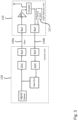
- FIG. 2 shows a conventional digital ROF system 200, where the ADC and DAC are provided in the RRU 210 instead of the central unit 230, which increases the hardware complexity of the RRU 210.
- many channels are put into one RRU (for example, 64 antennas in one RRU for massive MIMO, which means 64 RoF, 64 PA and other accessories such as filter and the like also inside the RRU). This substantially increases the size of the RRU and, thus, makes it difficult to deploy in practice.
- One of the main challenges of analog RoF systems is to increase the system linearity for long distance transmission (e.g. the chromatic dispersion effect in a 20 Km fiber), as illustrated by the following simple application scenario: OFDM (orthogonal frequency division multiplexing) baseband width 200 MHz; radio frequency 3.5 GHz; fiber length 20 Km; directly modulated lasers (DML); a single fiber for a single RF channel, where the downlink optical wavelength is 1550 nm and the uplink wavelength is 1310 nm.
- the single link performance ACPR adjacent channel power ratio
- a post-distorter can improve the uplink performance, but a training signal is needed as well, which, in turn, increases the complexity of the remote ratio unit, for instance, in terms of hardware.
- the training signal is required for compensating the nonlinearity of the RoF uplink, because otherwise it will result in a collapse of the performance (see Atso Hekkala et al: "Architectures for Joint Compensation of RoF and PA with Nonideal Feedback” Vehicular Technology Conference (VTC 2010-Spring), 2010 IEEE 71st May 2010 ; and Atso Hekkala et al: "Predistortion of Radio Over Fiber Links: Algorithms, Implementation, and Measurements", IEEE TRANSACTIONS ON CIRCUITS AND SYSTEMS-I: REGULAR PAPERS, VOL. 59, NO. 3, MARCH 2012. PP672-674 ).
- the training signal is usually in the digital baseband. If the baseband in the RRU is increased, a RF transceiver, a DAC and other components have to be added to the RRU, which will again increase the size of the RRU and, thus, might render such a RRU impractical for an actual deployment.
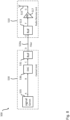
- the training signal is added by a training signal module 111 of the RRU 110, and an algorithm implemented in the central unit 130a is used to identify the uplink channel 120b.
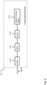
- Figure 4 illustrates the training signal 111 module for generating the conventional training signal used in the system shown in figure 3 in more detail.
- the training signal generation in the RRU 110 is realized by a digital baseband signal generator 111a, a DAC 111c, a RF modulator 111d, whose frequency is synchronized with the demodulation frequency at the central unit 130, a digital upconverter (DUC) 111b, and a synchronizing unit (Syn) for synchronizing the carrier.
- DUC digital upconverter
- Syn synchronizing unit
- a disclosure in connection with a described method may also hold true for a corresponding device or system configured to perform the method and vice versa.
- a corresponding device may include a unit to perform the described method step, even if such unit is not explicitly described or illustrated in the figures.
- implementations of the disclosure are based on the idea to replace the training signal generator of a conventional RRU 110 by a noise generator for generating a stimulus signal having well-defined statistical properties as the uplink ROF input signal and to perform a blind channel identification algorithm at the central unit.
- a noise generator for generating a stimulus signal having well-defined statistical properties as the uplink ROF input signal and to perform a blind channel identification algorithm at the central unit.
- the noise generator preferably a diode noise generator, is necessary to generate the stimulus signal in a remote radio unit according to an implementation.
- FIG. 5 shows a schematic diagram illustrating a base transceiver station 500 including a remote radio unit (RRU) 510 according to an implementation connected via and ROF downlink 520a and a ROF uplink 520b to a central unit 530 according to an implementation.
- RRU remote radio unit
- the base transceiver station 500 can comprise a plurality of remote radio units like the RRU 510 shown in figure 5 , which are connected (by a respective plurality of ROF links) to one or more central units like the central unit 530 shown in figure 5 .
- the remote radio unit 510 comprises a noise generator 511 configured to provide a RF noise signal having predefined statistical properties, in particular second-order statistics and/or higher-order statistics.
- the noise generator 511 is configured to provide a RF white noise signal having predefined statistical properties, in particular second-order statistics and/or higher-order statistics.
- the noise generator 511 is a diode noise generator.
- the remote radio unit 510 comprises a communication interface 513 configured to transmit the RF noise signal as a stimulus signal over a radio-over-fiber, ROF, uplink channel 520b between the remote radio unit 510 and the central unit 530 of the base transceiver station 500 for determining on the basis of the RF noise signal a pre-distortion of a target signal to be transmitted by the remote radio unit 510.
- the communication interface 513 is further configured to receive the pre-distorted target signal over a ROF downlink channel 520a between the remote radio unit 510 and the central unit (530) of the base transceiver station 500.
- the remote radio unit 510 comprises an antenna 515 for transmitting the pre-distorted target signal received by the communication interface 513.
- the central unit 530 of the base transceiver station 500 comprises a communication interface 531 configured to receive the RF noise signal as a stimulus signal over the radio-over-fiber, ROF, uplink channel 520b between the central unit 530 and the remote radio unit 510 of the base transceiver station 500.
- the central unit 530 comprises a pre-distortion unit 533 implementing an algorithm configured to pre-distort the target signal to be transmitted by the remote radio unit 510 on the basis of the RF noise signal received by the communication interface 531 as well as information about the predefined statistical properties, in particular second-order statistics and/or higher-order statistics, of the RF noise signal.
- this information about the predefined statistical properties of the RF noise signal can be retrieved from a memory of the central unit 530.
- the communication interface 531 of the central unit 530 is further configured to transmit the pre-distorted target signal over the ROF downlink channel 520a to the remote radio unit 510 of the base transceiver station 500.
- the remote radio unit 510 further comprises a power amplifier 517 configured to amplify the pre-distorted target signal received by the communication interface 513 from the central unit 530.
- the remote radio unit 510 further comprises a coupler 518 configured to couple a ROF downlink channel processing chain of the remote radio unit 510 (which, in the implementation shown in figure 5 includes the downlink portion of the communication interface 513, the power amplifier 517 as well as the antenna 515) to a ROF uplink channel processing chain of the remote radio unit 510 (which, in the implementation shown in figure 5 , includes the noise generator 511 and the uplink portion of the communication interface 513).
- a coupler 518 configured to couple a ROF downlink channel processing chain of the remote radio unit 510 (which, in the implementation shown in figure 5 includes the downlink portion of the communication interface 513, the power amplifier 517 as well as the antenna 515) to a ROF uplink channel processing chain of the remote radio unit 510 (which, in the implementation shown in figure 5 , includes the noise generator 511 and the uplink portion of the communication interface 513).
- the remote radio unit 510 further comprises a controller 512 configured to provide a control signal for triggering the noise generator 511 to provide the RF noise signal (shown in figure 12 ).
- the control signal for triggering the noise generator 511 can be provided by the central unit 530.
- the communication interface 513 of the remote radio unit 510 is further configured to receive a control signal from the central unit 530 of the base transceiver station 500 for triggering the noise generator 511 to provide the RF noise signal.
- the central unit 530 of the base transceiver station 500 further comprises a control unit configured to provide a control signal, wherein the communication interface 531 of the central unit 530 is configured to transmit the control signal to the remote radio unit 510 for triggering the noise generator 511 of the remote radio unit 510 to provide the RF noise signal.
- the central unit 530 of the base transceiver station 500 further comprises an analog-to-digital converter 537 and/or a digital-to-analog converter 536, wherein the pre-distortion unit 533 is configured to pre-distort the target signal in the digital domain, i.e. in the base-band.
- the noise generator 511 such as diode noise generator
- the noise generator 511 can be provided by a low cost element having a compact size, which is the only element necessary for providing the stimulus signal (contrary to the additional elements required by the conventional training signal module shown in figure 4 ).
- the uplink ROF channel 520b is then identified by the central unit 530 by applying the algorithm implemented in unit 533, in particular a blind channel identification algorithm, using the information about the predefined statistical properties, in particular second-order statistics (SOS) and/or higher-order statistics (HOS), of the RF noise signal, i.e. stimulus signal.
- SOS second-order statistics
- HOS higher-order statistics
- These statistical properties of the stimulus signal are available to the central unit 530, as they are defined by physical properties of the noise generator 511.
- 4 ⁇ denote the 4th-order statistic (HOS) information
- E ⁇ [a(n)2 ⁇ denotes the 2 nd -order statistic (SOS) information.
- this algorithm doesn't work with an input signal of Gaussian distribution: that suggests the HOS information cannot be exploited or only SOS information can be exploited.
- using the HOS information relies on a minimization of the cost function, which requires the ratio of the input signal's high-order statistic to the second-order statistic.
- This minimization will optimize the equalized signal's distribution (statistic) to approach the distribution of the input's signal.
- it can be proven that such optimization can be performed on a Gaussian signal. This is because the Gaussian signal after a linear channel will always remain a Gaussian signal, i.e. there is no difference in distribution.
- the pre-distortion unit 533 is configured to pre-distort the target signal to be transmitted by the remote radio unit 510 on the basis of the RF noise signal received by the communication interface 531 using a blind channel identification algorithm.
- the blind channel identification algorithm is a constant modulus algorithm, CMA.
- the remote radio unit 510 and the central unit 530 of the base transceiver station 500 can implement a SIMO architecture, which will be described in more detail in the following under further reference to figure 6 and which is particular useful in massive MIMO scenarios.
- the SIMO architecture can be natively supported by the RRU 510 according to an implementation further comprising a power splitter 516 with a respective power control unit 519, such as an AGC (Automatic Gain Control) unit, for stabilizing the uplink ROF input power.
- a power control unit 519 such as an AGC (Automatic Gain Control) unit
- the remote radio unit 510 further comprises a power splitter 516 configured to split the stimulus signal at least into a first stimulus signal and a second stimulus signal, wherein the uplink portion of the communication interface 513 is configured to transmit the first stimulus signal over the radio-over-fiber, ROF, uplink channel 520b between the remote radio unit 510 and the central unit 530 of the base transceiver station 500 and to transmit the second stimulus signal over a further radio-over-fiber, ROF, uplink channel 520c between the remote radio unit 510 and the central unit 530 of the base transceiver station 500.
- a power splitter 516 configured to split the stimulus signal at least into a first stimulus signal and a second stimulus signal
- the uplink portion of the communication interface 513 is configured to transmit the first stimulus signal over the radio-over-fiber, ROF, uplink channel 520b between the remote radio unit 510 and the central unit 530 of the base transceiver station 500 and to transmit the second stimulus signal over a further radio-over-fiber, ROF, uplink
- the remote radio unit 510 further comprises a first local power control unit 519, in particular automatic gain controller (AGC), configured to control the power of the first stimulus signal to be transmitted over the radio-over-fiber, ROF, uplink channel 520b between the remote radio unit 510 and the central unit 530 of the base transceiver station 500 and a second local power control unit 519, in particular automatic gain controller (AGC), configured to control the power of the second stimulus signal to be transmitted over the further radio-over-fiber, ROF, uplink channel 520c between the remote radio unit 510 and the central unit 530 of the base transceiver station 500.
- AGC automatic gain controller
- the remote radio unit 510 further comprises a global power controller 514 (illustrated in figure 15 and described in more detail further below) configured to control the power of the first stimulus signal and the second stimulus signal by implementing an uplink ROF power control loop.
- the downlink portion of the communication interface 513 of the RRU 510 can be configured to receive a desired target gain from the central unit 530 and the global power controller 514 can be configured to control the power of the first stimulus signal and the second stimulus signal by implementing an uplink ROF power control loop on the basis of the desired target gain.
- the desired target gain be determined by the central unit 530 such that the uplink RoF still operates in the linear regime, for instance, on the basis of a constant CDF (Cumulative Density Function) and/or a constant CCDF (Complementary Cumulative Density Function) of the received signal.
- CDF Cumulative Density Function
- CCDF Complementary Cumulative Density Function
- the multiple ROF channels shown in figure 6 are supposed to be different from each other (diversity condition) and the SOS-based blind equalization algorithm taking advantage of such diversity can be applied by the central unit 530 for high accuracy and low complexity in both the linear scenario as well as the and non-linear scenario.
- these types of algorithms do not require information about the statistical properties of the stimulus signal.
- the noise generator 511 shown in figure 6 is not necessary and can be replaced by a different stable signal source, such as the downlink signal or the uplink signal.
- implementations of the disclosure provide an uplink ROF power control loop, which is based on the finding that the uplink ROF input signal power is a key factor for the quality of the channel identification for both the uplink 520b and the downlink 520a.
- implementations of the disclosure provide a closed-loop power control architecture. This power control is executed by the RRU 510, while the power level, i.e. the target gain, is determined by the central unit 530.
- the uplink signal quality and/or the downlink signal quality can be fed to the uplink ROF power control unit 519 as information, ex. MSE, EVM, SER or BER.
- the RRU 510 and the central unit 530 are configured to implement the following scenario: for a given range of uplink ROF input signal power levels, execute at each power level the loop calibration, including uplink compensation (post-distortion) and downlink compensation (pre-distortion) then find the power level that yields the best downlink signal. More specifically, the respective power control unit 519 of the RRU 510 will follow the instructions on uplink ROF power level.
- the blind channel identification/equalization module of the central unit 530 can evaluate the equalized uplink signal's quality.
- the pre-distorter module of the central unit 530 can evaluate the equalized looped downlink signal's channel's quality.
- the uplink ROF power controller optimizes the uplink ROF power level based on the assessment of the UL/DL signal's quality.
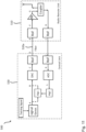
- Figure 8 illustrates the signal flow for a downlink transmission, where the signal flows from A to B, C, D, E, F, G, and then is emitted by the antenna 515.
- the signal generator 535 of the central unit 530 generates a 200MHz bandwidth OFDM baseband signal.
- the signal at A and B is the same for a 200MHz bandwidth OFDM baseband digital signal.
- the DAC 536 the signal is modulated to a 3.5 GHz frequency carrier, and then converted to an analog signal so that the output at C is an analog electronic signal with 3.5 GHz.
- the electronic signal is modulated onto an optical carrier, whose wavelength is 1550 nm so that D and E are optical signals.
- the downlink portion of the communication interface 513 converts the optical signal to an electronic signal, which is the inverse process of the process performed by the downlink portion of the communication interface 531 of the central unit 530.
- the signal is again an analog electronic signal with 3.5 GHz.
- the power amplifier 517 of the RRU 510 is provided for signal energy amplification from F to G.
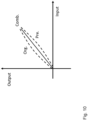
- the power amplifier 518 can have nonlinearity features, which distort the signal and increase out-of-band energy. In the prior art, this distorted signal is very difficult to recover by the receiver. To overcome this issue, it is known to implement a digital pre-distortion algorithm, which is referenced in figure 9 as "Alg1". Thus, in the implementation shown in figure 9 , the signal flowing from A to B is distorted by the digital pre-distortion algorithm "Alg1", which counteracts the nonlinearity features(s) of the power amplifier 517 mentioned above. This is illustrated in figure 10 , where the original (Org) signal has the non-linearity feature, the pre-distortion (Pre) algorithm counteracts the non-linearity feature, and the final combined signal (Comb) will have the ideal linearity.
- the pre-distortion algorithm can compensate any nonlinearities of the hardware modules. This, however, requires having information about the one or more nonlinearities introduced by a hardware module before designing any pre-distortion algorithm. This can be done using a training signal, as illustrated in figure 11 .
- the training signal is generated by the signal generation unit 535 (or provided thereto) and flows from A, to B, C, D, E, F and G.
- the goal is to achieve the same signal nonlinearity at G and L.
- Alg2 the whole nonlinearity model from A to G has to be represented and then pre-distorted by the algorithm "Alg1".
- some nonlinearity is involved as well, which is, however, not needed in Alg2.
- the remote radio unit 510 comprises a noise generator 511 configured to provide the stimulus signal as a RF noise signal having predefined statistical properties, in particular second-order statistics and/or higher-order statistics, known to the central unit 530.
- the corresponding signal flow is illustrated in figure 12 .
- the stimulus signal flows from N, to I, J, K, and L.
- the algorithm "Alg2" uses information about statistical properties of the stimulus signal, such as SOS information, to model uplink channel features.
- the controller 512 of the RRU 510 can be configured to provide a control signal to the noise generator 511 (illustrated at M in figure 12 ) for triggering the noise generator 511
- FIG 13 illustrates the signal flow in the SIMO implementations shown in figures 6 and 7 .
- the SIMO implementations are based on the idea to firstly describe the uplink channel feature and secondly compensate the uplink channel feature (as illustrated by the signal flow from H to L in figure 13 ).
- SIMO means one downlink channel and at least two uplink channels.
- a simple SIMO implementation, similar to the ones shown in figures 6 and 7 is illustrated in figure 13 .
- the RRU 510 can further comprise a respective power control unit 519, in particular a respective Automatic Gain Controller (AGC) to control different gains for different uplink channels 520b,c.
- AGC Automatic Gain Controller
- a SIMO system can be identified under the following conditions: (i) all channels in the system must be different enough from each other; (ii) the input sequence must be complex enough; and (iii) enough output samples need to be available.
- respective power control units 519 are implemented in the RRU 510 for adjusting the input power for every uplink channel, so that they can work differently.
- the training sequence provided by the central unit 510 can be arbitrarily complex and can be kept for sufficient time in order to obtain enough output samples for processing by the algorithm "Alg3".
- a two-steps maximum likelihood (TSML) algorithm can be implemented as algorithm "Alg3" in the central unit 530.
- Alg3 the received signal (vector) from multiple-channels
- the channel can be identified by using the following two-step ML algorithm:
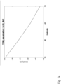
- FIG 14 The performance of the algorithm "Alg3" as a two-steps maximum likelihood (TSML) algorithm in the central unit 530 is illustrated in figure 14 .
- NMSE stands for the normalized mean square error between the equalized signal and input signal. It is observed that a low NMSE can be achieved in the high SNR region.
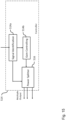
- FIG 15 shows a schematic diagram illustrating in more detail the global power controller 514 of the remote radio unit 510 shown in figure 13 .
- the controller 514 can have three main functions.
- the signal identification module 514a of the controller 514 is configured to identify a received input signal.
- the gain controlling module 514b will generate at a suitable time a gain control signal and send the gain control signal to the power splitter 516 for the different uplink channels 520b,c.
- the power splitter 516 of the controller 514 is configured to adjust the actual output power for the different uplink channels 520b,c.
- the controller 514 is capable of dealing with time-varying channels, for instance, by operating periodically.
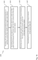
- FIG 16 shows a flow diagram illustrating a method 1600 of operating the remote radio unit 510 of the base transceiver station 500.
- the method 1600 comprises the steps of: providing 1601 a RF noise signal having predefined statistical properties, in particular second-order statistics and/or higher-order statistics; transmitting 1603 the RF noise signal as a stimulus signal over the radio-over-fiber uplink channel 520b between the remote radio unit 510 and the central unit 530 of the base transceiver station 500 for determining on the basis of the RF noise signal a pre-distortion of the target signal to be transmitted by the remote radio unit 510; receiving 1605 the pre-distorted target signal over the ROF downlink channel 520a between the remote radio unit 510 and the central unit 530 of the base transceiver station 500; and transmitting 1607 the pre-distorted target signal using the antenna 515 of the remote radio unit 510.
- Figure 17 shows a flow diagram illustrating a method 1700 of operating the central unit 530 of the base transceiver station 500.
- the method 1700 comprises the steps of: receiving 1701 a RF noise signal as a stimulus signal over the radio-over-fiber uplink channel 520b between the central unit 530 and the remote radio unit 510 of the base transceiver station 500; pre-distorting 1703 a target signal to be transmitted by the remote radio unit 510 on the basis of the RF noise signal and information about the predefined statistical properties, in particular second-order statistics and/or higher-order statistics, of the RF noise signal; and transmitting 1705 the pre-distorted target signal over a ROF downlink channel 520a to the remote radio unit 510 of the base transceiver station 500.
Landscapes
- Physics & Mathematics (AREA)
- Engineering & Computer Science (AREA)
- Computer Networks & Wireless Communication (AREA)
- Signal Processing (AREA)
- Electromagnetism (AREA)
- Nonlinear Science (AREA)
- Mobile Radio Communication Systems (AREA)
Claims (13)
- Unité radio distante (510) pour une station émettrice-réceptrice de base (500), dans laquelle l'unité radio distante (510) comprend :un générateur de bruit (511) configuré pour fournir un signal de bruit radiofréquence, RF, ayant des propriétés statistiques prédéfinies ;une interface de communication (513) configurée pour transmettre, à une unité centrale (530) de la station émettrice-réceptrice de base (500), le signal de bruit RF, reçu en provenance du générateur de bruit (511), en tant que signal de stimulus sur un canal de liaison montante radio sur fibre, ROF, (520b) entre l'unité radio distante (510) et l'unité centrale (530) de la station émettrice-réceptrice de base (500), dans laquelle l'interface de communication (513) est également configurée pour recevoir en provenance de l'unité centrale (530) un signal cible pré-distordu sur un canal de liaison descendante ROF (520a) entre l'unité radio distante (510) et l'unité centrale (530) de la station émettrice-réceptrice de base (500) ; etune antenne (515) destinée à transmettre le signal cible pré-distordu reçu par l'interface de communication (513) ;dans laquelle l'unité radio distante (510) comprend également un diviseur de puissance (516) configuré pour diviser le signal de stimulus en un premier signal de stimulus et un second signal de stimulus, dans laquelle l'interface de communication (513) est configurée pour transmettre le premier signal de stimulus sur le canal de liaison montante radio sur fibre, ROF, (520b) entre l'unité radio distante (510) et l'unité centrale (530) de la station émettrice-réceptrice de base (500) et pour transmettre le second signal de stimulus sur un autre canal de liaison montante radio sur fibre, ROF, (520c) entre l'unité radio distante (510) et l'unité centrale (530) de la station émettrice-réceptrice de base (500) ;dans laquelle l'unité radio distante (510) comprend également une première unité de commande de puissance locale (519) configurée pour commander la puissance du premier signal de stimulus à transmettre sur le canal de liaison montante radio sur fibre, ROF, (520b) entre l'unité radio distante (510) et l'unité centrale (530) de la station émettrice-réceptrice de base (500) et une seconde unité de commande de puissance locale (519) configurée pour commander la puissance du second signal de stimulus à transmettre sur l'autre canal de liaison montante radio sur fibre, ROF, (520c) entre l'unité radio distante (510) et l'unité centrale (530) de la station émettrice-réceptrice de base (500).
- Unité radio distante (510) selon la revendication 1, dans laquelle le générateur de bruit (511) est configuré pour fournir un signal de bruit blanc RF ayant des propriétés statistiques prédéfinies.
- Unité radio distante (510) selon la revendication 1 ou 2, dans laquelle l'unité radio distante (510) comprend également un amplificateur de puissance (517) configuré pour amplifier le signal cible pré-distordu reçu par l'interface de communication (513).
- Unité radio distante (510) selon l'une quelconque des revendications précédentes, dans laquelle l'unité radio distante (510) comprend également un coupleur (518) configuré pour coupler une chaîne de traitement de canal de liaison descendante ROF de l'unité radio distante (510) à une chaîne de traitement de canal de liaison montante ROF de l'unité radio distante (510).
- Unité radio distante (510) selon l'une quelconque des revendications précédentes, dans laquelle l'unité radio distante (510) comprend également un dispositif de commande (512) configuré pour fournir un signal de commande pour déclencher le générateur de bruit (511) pour fournir le signal de bruit RF.
- Unité radio distante (510) selon l'une quelconque des revendications précédentes, dans laquelle l'unité radio distante comprend également un dispositif de commande de puissance global (512) configuré pour commander la puissance du premier signal de stimulus et du second signal de stimulus en mettant en œuvre une boucle de commande de puissance ROF de liaison montante.
- Unité radio distante (510) selon la revendication 6, dans laquelle l'interface de communication (513) est configurée pour recevoir un gain cible souhaité de l'unité centrale (530) et le dispositif de commande de puissance global (512) est configuré pour commander la puissance du premier signal de stimulus et du second signal de stimulus en mettant en œuvre une boucle de commande de puissance ROF de liaison montante sur la base du gain cible souhaité.
- Unité radio distante (510) selon l'une quelconque des revendications précédentes, dans laquelle l'interface de communication (513) est également configurée pour recevoir un signal de commande en provenance de l'unité centrale (530) de la station émettrice-réceptrice de base (500) pour déclencher le générateur de bruit (511) afin de fournir le signal de bruit RF.
- Station émettrice-réceptrice de base (500) comprenant une ou plusieurs unités radio distantes (510) selon l'une quelconque des revendications 1 à 8, une unité centrale (530) et une ou plusieurs fibres optiques (520a-c) reliant l'une ou les plusieurs unités radio distantes (510) à l'unité centrale (530), dans laquelle l'unité centrale (530) comprend :une interface de communication (531) configurée pour recevoir, en provenance d'une unité radio distante (510) de la station émettrice-réceptrice de base (500), un signal de bruit RF en tant que signal de stimulus sur un canal de liaison montante radio sur fibre, ROF, (520b) entre l'unité centrale (530) et l'unité radio distante (510) de la station émettrice-réceptrice de base (500) ; etune unité de pré-distorsion (533) configurée pour pré-distordre un signal cible à transmettre par l'unité radio distante (510) sur la base du signal de bruit RF reçu par l'interface de communication (531) ;dans laquelle l'interface de communication (531) est également configurée pour transmettre le signal cible pré-distordu sur un canal de liaison descendante ROF (520a) à l'unité radio distante (510) de la station émettrice-réceptrice de base (500).
- Station émettrice-réceptrice de base (500) selon la revendication 9, dans laquelle l'unité de pré-distorsion (533) est configurée pour pré-distordre le signal cible à transmettre par l'unité radio distante (510) sur la base du signal de bruit RF reçu par l'interface de communication (531) à l'aide d'un algorithme d'identification de canal aveugle.
- Station émettrice-réceptrice de base (500) selon la revendication 10, dans laquelle l'algorithme d'identification de canal aveugle est un algorithme à module constant, CMA.
- Station émettrice-réceptrice de base (500) selon l'une quelconque des revendications 9 à 11, dans laquelle l'unité centrale (530) comprend également une unité de commande configurée pour fournir un signal de commande et dans laquelle l'interface de communication (531) est également configurée pour transmettre le signal de commande à l'unité radio distante (510) pour déclencher un générateur de bruit (511) de l'unité radio distante (510) pour fournir le signal de bruit RF.
- Station émettrice-réceptrice de base (500) selon l'une quelconque des revendications 9 à 12, dans laquelle l'unité centrale (530) comprend également un convertisseur analogique-numérique (537) et/ou un convertisseur numérique-analogique (536) et dans laquelle l'unité de pré-distorsion (533) est configurée pour pré-distordre le signal cible dans le domaine numérique.
Applications Claiming Priority (1)
| Application Number | Priority Date | Filing Date | Title |
|---|---|---|---|
| PCT/EP2018/063956 WO2019228608A1 (fr) | 2018-05-28 | 2018-05-28 | Unité radio distante et unité centrale pour station émettrice-réceptrice de base |
Publications (2)
| Publication Number | Publication Date |
|---|---|
| EP3782304A1 EP3782304A1 (fr) | 2021-02-24 |
| EP3782304B1 true EP3782304B1 (fr) | 2025-04-23 |
Family
ID=62495779
Family Applications (1)
| Application Number | Title | Priority Date | Filing Date |
|---|---|---|---|
| EP18728841.0A Active EP3782304B1 (fr) | 2018-05-28 | 2018-05-28 | Unité radio distante et unité centrale pour station émettrice-réceptrice de base |
Country Status (4)
| Country | Link |
|---|---|
| US (1) | US11271651B2 (fr) |
| EP (1) | EP3782304B1 (fr) |
| CN (1) | CN112088502B (fr) |
| WO (1) | WO2019228608A1 (fr) |
Families Citing this family (5)
| Publication number | Priority date | Publication date | Assignee | Title |
|---|---|---|---|---|
| EP3857740B1 (fr) | 2018-10-26 | 2024-10-02 | Huawei Technologies Co., Ltd. | Unité radio à distance et unité centrale destinées à un système à entrées multiples et sorties multiples |
| CN111245377B (zh) * | 2020-03-20 | 2021-11-05 | 厦门大学 | 一种基于直接学习结构的数字预失真系统及方法 |
| CN113595642B (zh) * | 2020-04-30 | 2022-10-18 | 华为技术有限公司 | 通信设备和通信系统 |
| EP4037207A1 (fr) * | 2021-01-28 | 2022-08-03 | Nokia Solutions and Networks Oy | Appareil et système radio |
| US20250030967A1 (en) * | 2023-07-21 | 2025-01-23 | Zhejiang University | Distributed multi-antenna collaborative phase stabilization method and apparatus for future broadband wireless communication |
Family Cites Families (8)
| Publication number | Priority date | Publication date | Assignee | Title |
|---|---|---|---|---|
| US5263033A (en) * | 1990-06-22 | 1993-11-16 | At&T Bell Laboratories | Joint data and channel estimation using fast blind trellis search |
| US20080063041A1 (en) * | 2006-09-08 | 2008-03-13 | Noam Galperin | Fast training equalization of a signal |
| US8260145B2 (en) * | 2008-03-12 | 2012-09-04 | Deepnarayan Gupta | Digital radio frequency tranceiver system and method |
| CN102082752B (zh) * | 2010-02-25 | 2014-03-19 | 电信科学技术研究院 | 一种数字预失真处理方法及设备 |
| US9166700B2 (en) * | 2010-03-21 | 2015-10-20 | Alcatel Lucent | Tunable receiver |
| EP3342068A1 (fr) * | 2015-08-24 | 2018-07-04 | Telefonaktiebolaget LM Ericsson (PUBL) | Commande d'un émetteur optique dans un système radio sur fibre |
| JP6750199B2 (ja) * | 2015-09-28 | 2020-09-02 | 富士通株式会社 | 通信装置および通信システム |
| JP2018046434A (ja) * | 2016-09-15 | 2018-03-22 | 富士通株式会社 | 送信装置 |
-
2018
- 2018-05-28 WO PCT/EP2018/063956 patent/WO2019228608A1/fr not_active Ceased
- 2018-05-28 EP EP18728841.0A patent/EP3782304B1/fr active Active
- 2018-05-28 CN CN201880093104.8A patent/CN112088502B/zh active Active
-
2020
- 2020-11-25 US US17/105,304 patent/US11271651B2/en active Active
Also Published As
| Publication number | Publication date |
|---|---|
| WO2019228608A1 (fr) | 2019-12-05 |
| EP3782304A1 (fr) | 2021-02-24 |
| US20210083772A1 (en) | 2021-03-18 |
| CN112088502A (zh) | 2020-12-15 |
| CN112088502B (zh) | 2022-04-12 |
| US11271651B2 (en) | 2022-03-08 |
Similar Documents
| Publication | Publication Date | Title |
|---|---|---|
| US11271651B2 (en) | Remote radio unit and a central unit for a base transceiver station | |
| US8428525B2 (en) | Predistorter for a multi-antenna transmitter | |
| Fernando et al. | Adaptive asymmetric linearization of radio over fiber links for wireless access | |
| US8867931B2 (en) | Digital radio frequency transceiver system and method | |
| US11563493B2 (en) | Remote radio unit and central unit for multiple-input multiple-output system | |
| JP7020752B2 (ja) | 信号伝送における負荷変調 | |
| Han et al. | Linearity improvement of directly-modulated multi-IF-over-fibre LTE-A mobile fronthaul link using shunt diode predistorter | |
| Zhang et al. | Memory-polynomial digital pre-distortion for linearity improvement of directly-modulated multi-IF-over-fiber LTE mobile fronthaul | |
| US9735857B2 (en) | Predistortion in satellite signal transmission systems | |
| US11909441B2 (en) | Base station and a method for operating the base station | |
| Noweir et al. | Carrier aggregated radio-over-fiber downlink for achieving 2Gbps for 5G applications | |
| Noweir et al. | Linearization of radio-over-fiber cloud-RAN transmitters using pre-and post-distortion techniques | |
| Hadi et al. | 5G NR MIMO enabled multiband fiber wireless system using analog optical front haul | |
| Mateo et al. | Digital predistortion of a full-duplex Radio-over-Fiber mobile fronthaul link with feedback loop | |
| Wang et al. | Photonic generation of high fidelity RF sources for mobile communications | |
| Kim et al. | Blind compensation of nonlinear waveform distortions in radio-over-fiber system | |
| Mateo et al. | Experimental evaluation of the feedback loop effects in digital predistortion of a radio-over-fiber system | |
| Fernando et al. | Look-up table based adaptive predistortion for dynamic range enhancement in a radio over fiber link | |
| Park et al. | Distortion mitigation in IFoF system employing frequency-separated DPD | |
| Hadi et al. | 5G NR Fiber Wireless System using Analog Optical Front Haul for Long Reach Applications | |
| Mateo et al. | Linearization of a radio-over-fiber mobile fronthaul with feedback loop | |
| O'Droma et al. | Linearity and efficiency issues in RF power amplifiers for future broadband wireless access systems | |
| Liu et al. | Transmission of four channels SCM over fiber and nonlinear compensation for RSOA external modulators | |
| Lozhkin et al. | Impact of radio over fiber links in feedback on linearization performances of RF power amplifiers |
Legal Events
| Date | Code | Title | Description |
|---|---|---|---|
| STAA | Information on the status of an ep patent application or granted ep patent |
Free format text: STATUS: UNKNOWN |
|
| STAA | Information on the status of an ep patent application or granted ep patent |
Free format text: STATUS: THE INTERNATIONAL PUBLICATION HAS BEEN MADE |
|
| PUAI | Public reference made under article 153(3) epc to a published international application that has entered the european phase |
Free format text: ORIGINAL CODE: 0009012 |
|
| STAA | Information on the status of an ep patent application or granted ep patent |
Free format text: STATUS: REQUEST FOR EXAMINATION WAS MADE |
|
| 17P | Request for examination filed |
Effective date: 20201118 |
|
| AK | Designated contracting states |
Kind code of ref document: A1 Designated state(s): AL AT BE BG CH CY CZ DE DK EE ES FI FR GB GR HR HU IE IS IT LI LT LU LV MC MK MT NL NO PL PT RO RS SE SI SK SM TR |
|
| AX | Request for extension of the european patent |
Extension state: BA ME |
|
| DAV | Request for validation of the european patent (deleted) | ||
| DAX | Request for extension of the european patent (deleted) | ||
| GRAP | Despatch of communication of intention to grant a patent |
Free format text: ORIGINAL CODE: EPIDOSNIGR1 |
|
| STAA | Information on the status of an ep patent application or granted ep patent |
Free format text: STATUS: GRANT OF PATENT IS INTENDED |
|
| INTG | Intention to grant announced |
Effective date: 20241202 |
|
| GRAS | Grant fee paid |
Free format text: ORIGINAL CODE: EPIDOSNIGR3 |
|
| GRAA | (expected) grant |
Free format text: ORIGINAL CODE: 0009210 |
|
| STAA | Information on the status of an ep patent application or granted ep patent |
Free format text: STATUS: THE PATENT HAS BEEN GRANTED |
|
| AK | Designated contracting states |
Kind code of ref document: B1 Designated state(s): AL AT BE BG CH CY CZ DE DK EE ES FI FR GB GR HR HU IE IS IT LI LT LU LV MC MK MT NL NO PL PT RO RS SE SI SK SM TR |
|
| REG | Reference to a national code |
Ref country code: GB Ref legal event code: FG4D |
|
| REG | Reference to a national code |
Ref country code: CH Ref legal event code: EP |
|
| REG | Reference to a national code |
Ref country code: DE Ref legal event code: R096 Ref document number: 602018081304 Country of ref document: DE |
|
| REG | Reference to a national code |
Ref country code: IE Ref legal event code: FG4D |
|
| PGFP | Annual fee paid to national office [announced via postgrant information from national office to epo] |
Ref country code: DE Payment date: 20250408 Year of fee payment: 8 |
|
| REG | Reference to a national code |
Ref country code: NL Ref legal event code: MP Effective date: 20250423 |
|
| PG25 | Lapsed in a contracting state [announced via postgrant information from national office to epo] |
Ref country code: NL Free format text: LAPSE BECAUSE OF FAILURE TO SUBMIT A TRANSLATION OF THE DESCRIPTION OR TO PAY THE FEE WITHIN THE PRESCRIBED TIME-LIMIT Effective date: 20250423 |
|
| REG | Reference to a national code |
Ref country code: AT Ref legal event code: MK05 Ref document number: 1788826 Country of ref document: AT Kind code of ref document: T Effective date: 20250423 |
|
| PG25 | Lapsed in a contracting state [announced via postgrant information from national office to epo] |
Ref country code: FI Free format text: LAPSE BECAUSE OF FAILURE TO SUBMIT A TRANSLATION OF THE DESCRIPTION OR TO PAY THE FEE WITHIN THE PRESCRIBED TIME-LIMIT Effective date: 20250423 Ref country code: ES Free format text: LAPSE BECAUSE OF FAILURE TO SUBMIT A TRANSLATION OF THE DESCRIPTION OR TO PAY THE FEE WITHIN THE PRESCRIBED TIME-LIMIT Effective date: 20250423 Ref country code: PT Free format text: LAPSE BECAUSE OF FAILURE TO SUBMIT A TRANSLATION OF THE DESCRIPTION OR TO PAY THE FEE WITHIN THE PRESCRIBED TIME-LIMIT Effective date: 20250825 |
|
| REG | Reference to a national code |
Ref country code: LT Ref legal event code: MG9D |
|
| PG25 | Lapsed in a contracting state [announced via postgrant information from national office to epo] |
Ref country code: GR Free format text: LAPSE BECAUSE OF FAILURE TO SUBMIT A TRANSLATION OF THE DESCRIPTION OR TO PAY THE FEE WITHIN THE PRESCRIBED TIME-LIMIT Effective date: 20250724 Ref country code: NO Free format text: LAPSE BECAUSE OF FAILURE TO SUBMIT A TRANSLATION OF THE DESCRIPTION OR TO PAY THE FEE WITHIN THE PRESCRIBED TIME-LIMIT Effective date: 20250723 |
|
| PG25 | Lapsed in a contracting state [announced via postgrant information from national office to epo] |
Ref country code: PL Free format text: LAPSE BECAUSE OF FAILURE TO SUBMIT A TRANSLATION OF THE DESCRIPTION OR TO PAY THE FEE WITHIN THE PRESCRIBED TIME-LIMIT Effective date: 20250423 |
|
| PG25 | Lapsed in a contracting state [announced via postgrant information from national office to epo] |
Ref country code: BG Free format text: LAPSE BECAUSE OF FAILURE TO SUBMIT A TRANSLATION OF THE DESCRIPTION OR TO PAY THE FEE WITHIN THE PRESCRIBED TIME-LIMIT Effective date: 20250423 |
|
| PG25 | Lapsed in a contracting state [announced via postgrant information from national office to epo] |
Ref country code: HR Free format text: LAPSE BECAUSE OF FAILURE TO SUBMIT A TRANSLATION OF THE DESCRIPTION OR TO PAY THE FEE WITHIN THE PRESCRIBED TIME-LIMIT Effective date: 20250423 |
|
| PG25 | Lapsed in a contracting state [announced via postgrant information from national office to epo] |
Ref country code: AT Free format text: LAPSE BECAUSE OF FAILURE TO SUBMIT A TRANSLATION OF THE DESCRIPTION OR TO PAY THE FEE WITHIN THE PRESCRIBED TIME-LIMIT Effective date: 20250423 |
|
| PG25 | Lapsed in a contracting state [announced via postgrant information from national office to epo] |
Ref country code: RS Free format text: LAPSE BECAUSE OF FAILURE TO SUBMIT A TRANSLATION OF THE DESCRIPTION OR TO PAY THE FEE WITHIN THE PRESCRIBED TIME-LIMIT Effective date: 20250723 |
|
| PG25 | Lapsed in a contracting state [announced via postgrant information from national office to epo] |
Ref country code: IS Free format text: LAPSE BECAUSE OF FAILURE TO SUBMIT A TRANSLATION OF THE DESCRIPTION OR TO PAY THE FEE WITHIN THE PRESCRIBED TIME-LIMIT Effective date: 20250823 |
|
| PG25 | Lapsed in a contracting state [announced via postgrant information from national office to epo] |
Ref country code: LV Free format text: LAPSE BECAUSE OF FAILURE TO SUBMIT A TRANSLATION OF THE DESCRIPTION OR TO PAY THE FEE WITHIN THE PRESCRIBED TIME-LIMIT Effective date: 20250423 |
|
| REG | Reference to a national code |
Ref country code: CH Ref legal event code: H13 Free format text: ST27 STATUS EVENT CODE: U-0-0-H10-H13 (AS PROVIDED BY THE NATIONAL OFFICE) Effective date: 20251223 |
|
| PG25 | Lapsed in a contracting state [announced via postgrant information from national office to epo] |
Ref country code: SM Free format text: LAPSE BECAUSE OF FAILURE TO SUBMIT A TRANSLATION OF THE DESCRIPTION OR TO PAY THE FEE WITHIN THE PRESCRIBED TIME-LIMIT Effective date: 20250423 Ref country code: DK Free format text: LAPSE BECAUSE OF FAILURE TO SUBMIT A TRANSLATION OF THE DESCRIPTION OR TO PAY THE FEE WITHIN THE PRESCRIBED TIME-LIMIT Effective date: 20250423 |
|
| PG25 | Lapsed in a contracting state [announced via postgrant information from national office to epo] |
Ref country code: LU Free format text: LAPSE BECAUSE OF NON-PAYMENT OF DUE FEES Effective date: 20250528 |
|
| PG25 | Lapsed in a contracting state [announced via postgrant information from national office to epo] |
Ref country code: CH Free format text: LAPSE BECAUSE OF NON-PAYMENT OF DUE FEES Effective date: 20250531 |
|
| PG25 | Lapsed in a contracting state [announced via postgrant information from national office to epo] |
Ref country code: CZ Free format text: LAPSE BECAUSE OF FAILURE TO SUBMIT A TRANSLATION OF THE DESCRIPTION OR TO PAY THE FEE WITHIN THE PRESCRIBED TIME-LIMIT Effective date: 20250423 |
|
| PG25 | Lapsed in a contracting state [announced via postgrant information from national office to epo] |
Ref country code: EE Free format text: LAPSE BECAUSE OF FAILURE TO SUBMIT A TRANSLATION OF THE DESCRIPTION OR TO PAY THE FEE WITHIN THE PRESCRIBED TIME-LIMIT Effective date: 20250423 |
|
| REG | Reference to a national code |
Ref country code: DE Ref legal event code: R097 Ref document number: 602018081304 Country of ref document: DE |
|
| PG25 | Lapsed in a contracting state [announced via postgrant information from national office to epo] |
Ref country code: RO Free format text: LAPSE BECAUSE OF FAILURE TO SUBMIT A TRANSLATION OF THE DESCRIPTION OR TO PAY THE FEE WITHIN THE PRESCRIBED TIME-LIMIT Effective date: 20250423 Ref country code: SK Free format text: LAPSE BECAUSE OF FAILURE TO SUBMIT A TRANSLATION OF THE DESCRIPTION OR TO PAY THE FEE WITHIN THE PRESCRIBED TIME-LIMIT Effective date: 20250423 |
|
| PG25 | Lapsed in a contracting state [announced via postgrant information from national office to epo] |
Ref country code: IT Free format text: LAPSE BECAUSE OF FAILURE TO SUBMIT A TRANSLATION OF THE DESCRIPTION OR TO PAY THE FEE WITHIN THE PRESCRIBED TIME-LIMIT Effective date: 20250423 |
|
| REG | Reference to a national code |
Ref country code: BE Ref legal event code: MM Effective date: 20250531 |
|
| PG25 | Lapsed in a contracting state [announced via postgrant information from national office to epo] |
Ref country code: MC Free format text: LAPSE BECAUSE OF FAILURE TO SUBMIT A TRANSLATION OF THE DESCRIPTION OR TO PAY THE FEE WITHIN THE PRESCRIBED TIME-LIMIT Effective date: 20250423 |
|
| PLBE | No opposition filed within time limit |
Free format text: ORIGINAL CODE: 0009261 |
|
| STAA | Information on the status of an ep patent application or granted ep patent |
Free format text: STATUS: NO OPPOSITION FILED WITHIN TIME LIMIT |
|
| REG | Reference to a national code |
Ref country code: CH Ref legal event code: L10 Free format text: ST27 STATUS EVENT CODE: U-0-0-L10-L00 (AS PROVIDED BY THE NATIONAL OFFICE) Effective date: 20260304 |
|
| 26N | No opposition filed |
Effective date: 20260126 |
|
| PGFP | Annual fee paid to national office [announced via postgrant information from national office to epo] |
Ref country code: GB Payment date: 20260325 Year of fee payment: 9 |
|
| PG25 | Lapsed in a contracting state [announced via postgrant information from national office to epo] |
Ref country code: IE Free format text: LAPSE BECAUSE OF NON-PAYMENT OF DUE FEES Effective date: 20250528 |
|
| PG25 | Lapsed in a contracting state [announced via postgrant information from national office to epo] |
Ref country code: BE Free format text: LAPSE BECAUSE OF NON-PAYMENT OF DUE FEES Effective date: 20250531 |
|
| PG25 | Lapsed in a contracting state [announced via postgrant information from national office to epo] |
Ref country code: FR Free format text: LAPSE BECAUSE OF NON-PAYMENT OF DUE FEES Effective date: 20250623 |