EP3782443A2 - Machine de traitement du sol agricole destinée au traitement des cultures sur rang - Google Patents
Machine de traitement du sol agricole destinée au traitement des cultures sur rang Download PDFInfo
- Publication number
- EP3782443A2 EP3782443A2 EP20186154.9A EP20186154A EP3782443A2 EP 3782443 A2 EP3782443 A2 EP 3782443A2 EP 20186154 A EP20186154 A EP 20186154A EP 3782443 A2 EP3782443 A2 EP 3782443A2
- Authority
- EP
- European Patent Office
- Prior art keywords
- coulter
- soil cultivation
- cultivation device
- frame
- carrier vehicle
- Prior art date
- Legal status (The legal status is an assumption and is not a legal conclusion. Google has not performed a legal analysis and makes no representation as to the accuracy of the status listed.)
- Granted
Links
Images


Classifications
-
- A—HUMAN NECESSITIES
- A01—AGRICULTURE; FORESTRY; ANIMAL HUSBANDRY; HUNTING; TRAPPING; FISHING
- A01B—SOIL WORKING IN AGRICULTURE OR FORESTRY; PARTS, DETAILS, OR ACCESSORIES OF AGRICULTURAL MACHINES OR IMPLEMENTS, IN GENERAL
- A01B63/00—Lifting or adjusting devices or arrangements for agricultural machines or implements
- A01B63/002—Devices for adjusting or regulating the position of tools or wheels
- A01B63/008—Vertical adjustment of tools
-
- A—HUMAN NECESSITIES
- A01—AGRICULTURE; FORESTRY; ANIMAL HUSBANDRY; HUNTING; TRAPPING; FISHING
- A01B—SOIL WORKING IN AGRICULTURE OR FORESTRY; PARTS, DETAILS, OR ACCESSORIES OF AGRICULTURAL MACHINES OR IMPLEMENTS, IN GENERAL
- A01B63/00—Lifting or adjusting devices or arrangements for agricultural machines or implements
- A01B63/14—Lifting or adjusting devices or arrangements for agricultural machines or implements for implements drawn by animals or tractors
- A01B63/16—Lifting or adjusting devices or arrangements for agricultural machines or implements for implements drawn by animals or tractors with wheels adjustable relatively to the frame
Definitions
- the present invention relates to an agricultural soil cultivation machine for agricultural use or for cultivating row crops.
- the invention relates in particular to a soil cultivation device, for example in the form of a coulter unit with or without a depth guide roller, and a control option for influencing a coulter unit and / or for its variable positioning.
- tillage machines in particular hoeing devices
- a soil cultivating machine goes, for example, from the DE 36 16 403 A1 already emerged.
- a chopping device is described with a machine beam composed of a central frame and two side frames, on which tools for row-wise cultivation of an agricultural area can be attached at a distance from one another.
- the side frames In order to achieve a favorable overall center of gravity in relation to an agricultural towing vehicle in the transport position, provision is made for the side frames to be arranged offset relative to the central frame in the direction of travel.
- sliding frames are equipped with other tools such as seed coulters, it makes sense to take suitable measures to ensure a desired pressure force and to ensure that the seed coulters can evade in the event of inadmissibly high loads or when they hit obstacles.
- the DE 1 731 011 B1 a tool carrier with a parallelogram-like suspension device, in which a soil cultivation tool and a depth control roller are pressed against the soil by means of spring force and, if necessary, can avoid obstacles or resistance in the soil.
- the known soil cultivation devices are each designed for specific conditions of use and have limited variability.
- a primary aim of the present invention is therefore to create additional equipment variants for known soil cultivation machines which also avoid various disadvantages of known tool suspensions.
- the aim of the present invention is to create a possibility with simple means to be able to use known soil cultivation machines even more flexibly and in particular to carry out both soil cultivation (e.g. hoeing) and sowing by means of such machines by means of only one share or share body can.
- the invention proposes a soil cultivation device for agricultural use that is mounted or mountable on a carrier vehicle, with the features of claim 1.
- Advantageous refinements and developments of the invention are specified in the respective dependent claims.
- the soil cultivation device comprises at least one coulter frame, which is height-adjustable or mounted at a defined height on the carrier vehicle, with a chopping and / or sowing coulter, which coulter frame carries a depth guide roller which is mounted on a bracket at a defined height with respect to the chopping and / or sowing coulter or is height-adjustable to this .
- the depth control roller can also be referred to as a pressure roller and / or pressure roller.
- hoe share can be used for pure cultivation of the soil without sowing and can thus be used in particular for mechanical weed control
- a seed share can also be used for sowing, in particular for distributing agricultural goods such as seeds, fertilizer or the like.
- the coulter frame can, however, also be designed in such a way that different coulters, such as hoe and seed coulters, can be attached to it in order to to be able to carry out different chopping work and / or to be able to carry out different distribution processes of agricultural distribution goods.
- the holder allows the depth control roller to be arranged in relation to a working direction of the carrier vehicle and the soil cultivation device in front of the chopping and / or sowing coulter or behind the chipping and / or sowing coulter.
- An assembly or arrangement of the depth control roller in relation to the working direction of the carrier vehicle in front of the chopping and / or sowing coulter has proven to be particularly advantageous in mechanical weed control, provided the chopping and / or sowing coulter is only designed as a chopping coulter.
- an exact depth control of the hoe share is necessary.
- the arrangement of the depth control roller in the working direction of the carrier vehicle in front of the hoe share also makes sense so that the grasses and / or weeds or the like that have been uprooted by means of the hoe share are not pressed back into the earth and thus root again. Instead, the uprooted grasses and / or weeds can lie on top of the ground loosened by means of the hoe and then dry up there.
- the depth guide roller can be used in particular to define and maintain an exact or desired working depth of the sowing coulter and thus to define and maintain an exact placement depth of agricultural distribution material.
- the agricultural distribution material can be pressed into the arable soil by means of the depth control roller, which is achieved accordingly with a depth control roller arranged downstream of the seed coulter.
- the seed coulter can also be assigned a seed line which can be fed with seed from a tank or storage container.
- the coulter frame together with the chopping and / or sowing coulter attached to it, can be movably mounted on the carrier vehicle or on an intermediate carrier arranged there be mounted with at least two roughly parallel arms, which are towed in relation to the working direction of the carrier vehicle and the soil cultivation device.
- the four-joint suspension can in particular be designed in the form of a parallelogram, by means of which the hoe and / or seed coulter is mounted on the coulter frame of the carrier vehicle in a pivotable and preferably height-adjustable manner. Due to the height adjustability, the respective working depth of the hoe and / or seed coulter can be varied and adjusted.
- the chopping and / or sowing coulter To adjust the height of the chopping and / or sowing coulter, it comprises a large number of spaced apart openings on its handle, through which openings a screw connection can be used to fix the chopping and / or sowing coulter at a defined height on the coulter frame.
- the at least two towed links enclose an angle between approximately 10 ° and approximately 80 ° to a horizontal in a working position of the soil cultivation device.
- the at least two towed links can be divided into an upper link and a lower link.
- the four-bar suspension in particular the parallelogram, can be designed such that the upper link and the lower link are oriented in a working position from top front to bottom back, opposite a forward direction of the chopping and / or sowing coulter or the carrier vehicle.
- Such an arrangement of the at least two links, in particular the upper link and the lower link, has the advantage that the hoe and / or sowing coulter move both backwards and upwards when it hits a stone or an obstacle or the like can, whereas hoe and / or seed coulters on largely horizontal links can largely only move upwards or whereas hoe and / or seed coulters on largely vertical links can largely only move backwards.
- Another advantage of the described arrangement of the at least two links is that the forces required for prestressing against an arable land can be reduced so that sufficiently high coulter pressures or coulter forces can be achieved even with low prestressing forces.
- This has the advantage that the components required to generate pretensioning forces have to meet significantly lower requirements (for example in terms of durability) and whereby the hoe and / or sowing coulter or the coulter frame can be constructed much more easily.
- the depth guide roller can be fixed to the holder by means of socket pins and, in particular, can be removed from there and attached to the holder without tools. Because of this, the depth control roller can be changed and / or exchanged quickly and without great effort. In addition, all other fastening methods of the depth control roller on the holder would be conceivable.
- the depth control roller is adjustable in its relative height to the holder and / or to the coulter frame of the hoe and / or seed coulter and can be fixed at this set height.
- the depth control roller can thus be individually adapted and / or adjusted to the respective soil cultivation processes and / or in particular to the respective soil conditions, which enables an exact depth control of the hoe and / or seed coulter.
- the depth control roller can be remounted quickly and without great effort, so that, for example, the depth control roller in relation to a working direction of the carrier vehicle and the soil cultivation device in front of the hoe and / or seed coulter or behind the chopping and / or or coulter is attached.
- different and in particular spaced apart openings can be provided, into which a screw connection can be inserted to fix the depth guide roller at a defined height on the holder.
- the invention further proposes a soil cultivation device for agricultural use that is mounted or mounted on a carrier vehicle, with the features of independent claim 6.
- the soil cultivation device comprises at least one suspension frame which is height-adjustable on the carrier vehicle or located at a defined height, a four-bar suspension mounted movably thereon with at least two approximately parallel arms that are towed in relation to a working direction of the carrier vehicle and the soil cultivation device, and a coulter frame mounted on the arms so that it can move vertically with a hoe and / or seed coulter rigidly attached to it, the at least two towed handlebars in one Include working position of the soil cultivation device at an angle between about 10 ° and about 80 ° to a horizontal.
- a controllable actuator for applying a variable preload and / or restoring force to the link and / or for adjusting the angle of the link relative to the suspension frame and thus for adjusting the height of the coulter frame is arranged.
- controllable actuator is formed by an adjusting cylinder that works with adjustable or controllable fluidic pressure, in particular by a single-acting or double-acting hydraulic cylinder or pneumatic cylinder.
- controllable actuator can also be formed by two single-acting hydraulic cylinders or pneumatic cylinders working in opposite directions.
- the hydraulic or pneumatic cylinder has at least one chamber that can be acted upon by variable pressure, in particular for generating a variable pretensioning force.
- the hydraulic or pneumatic cylinder has two chambers which can be acted upon by variable pressures and which can each be controlled differently, in particular for generating a variable pretensioning force and for lifting the coulters.
- the working depth of the hoe and / or sowing coulter can be adjusted as desired with regard to the prevailing soil conditions and working and / or spreading depth and in its excavation movement.
- At least two coulters or cylinders can be acted upon by means of a valve with approximately the same pressure values.
- the valve is part of a valve of the cylinder or that the valve is integrated into the cylinder. That is, the valve and the cylinder can comprise a common housing.
- the hoe and / or seed coulter is or can be moved between two positions by means of the actuator.
- the actuator can in particular be designed in such a way to convert the hoe and / or sowing coulter into a to move raised transport position.
- the actuator should be designed in such a way that it can be used to press the hoe and / or seed coulter with a defined and / or definable force against a field and / or with a so-called defined and / or definable coulter pressure along a field.
- the coulters When using a single-acting cylinder, the coulters can also be lifted out when they hit an obstacle, a stone or the like by means of a corresponding suspension, in particular by means of compression springs.
- controllable actuator is formed by a controllable or regulatable electric linear motor.
- the four-joint suspension with the coulter frame mounted on the at least two links so that it can move vertically is formed by a parallelogram suspension, in which an upper and a lower link are arranged approximately parallel to one another and are approximately the same Have lengths between their joint axes.
- the at least two towed links can be divided into an upper link and a lower link.
- the four-bar suspension in particular the parallelogram, can be designed in such a way that the upper link and the lower link are oriented in a working position from top front to bottom rear, opposite a forward direction of the chopping and / or sowing coulter or the carrier vehicle.
- Such an arrangement of the at least two links, in particular the upper link and the lower link, has the advantage that the hoe and / or sowing coulter move both backwards and upwards when it hits a stone or an obstacle or the like can, whereas hoe and / or seed coulters on largely horizontal handlebars can largely only move upwards or whereas hoe and / or seed coulters on largely vertical handlebars can largely only move backwards.
- a further advantage of the described arrangement of the at least two links is that the forces required for prestressing in relation to an arable area can be reduced, so that even with low prestressing forces sufficiently high coulter pressures or coulter forces can be achieved.
- This has the advantage that the components required to generate pre-tensioning forces have to meet significantly lower requirements (e.g. durability) and, in addition, the hacking and / or sowing coulter or the coulter frame can be constructed much more easily.
- controllable actuator can be used to control or regulate a coulter pressure when the chopping and / or sowing coulter is in engagement with a soil to be worked and / or for lifting the coulter frame in order to pull the chopping and / or sowing coulter out of the To bring interference with the arable soil.
- the hoe and / or seed coulter is attached to the coulter frame in an exchangeable manner.
- the attachment of the chopping and / or sowing coulter to the coulter frame can for example take place in a non-positive manner, in particular by means of screw connections or the like.
- the hoe and / or seed coulter can be changed, dismantled and / or exchanged quickly and without great effort in the event of wear and / or during maintenance and / or when converting the machine.
- the hoe and / or seed coulter can be moved between two positions by means of the controllable actuator.
- the hoe and / or seed coulter can be moved or pivoted between a working position and a transport position, in particular in a position raised or raised relative to the arable land.
- a control device can be provided to control the actuator, in particular the multiplicity of actuators.
- it can be equipped with a corresponding pressure sensor system, for example.
- a sensor system it would also be possible for a sensor system to be attached to at least one chopping and / or sowing coulter for detecting a force acting on the chopping and / or sowing coulter and / or the depth guide roller.
- an activation, in particular coulter pressure regulation is automatically regulated and / or controlled as a function of a determined force.
- an operator only needs to define a setpoint and / or a setpoint depth and then the regulation takes place automatically.
- the four-bar suspension which is movably mounted on the suspension frame of the carrier vehicle, with the towed links and the coulter frame mounted vertically on the handlebars with attached chopping and / or sowing coulter is adjustable transversely to a working direction of the carrier vehicle and / or transversely to a central longitudinal axis of the carrier vehicle or the soil cultivation device in the horizontal direction. Due to the horizontal adjustability of the four-joint suspension on the suspension frame, the soil cultivation machine can be individually adapted and / or set to the respective environmental and / or application conditions or requirements.
- a rail system is arranged between the suspension frame attached to the carrier vehicle and the four-bar suspension, with the aid of which the four-bar suspension with the coulter frame mounted on it can be displaced transversely to the working direction of the carrier vehicle.
- the four-joint suspension can be mounted at different positions on the rail system, in particular along the longitudinal direction of the rail system and / or transversely to the working direction of the carrier vehicle.
- the rail system can in particular be composed of a slide frame and a guide frame.
- the four-joint suspensions of the hoe and / or seed coulters can in particular be mounted and / or fastened to the slide frame.
- the slide frame can be displaced relative to the guide frame by means of at least one actuator, for example in the form of a hydraulic and / or pneumatic cylinder.
- the rail system has proven to be particularly advantageous in that the chopping and / or sowing coulters can each be shifted into a position required for the respective work to be carried out by means of the chopping and / or sowing coulters. For example, a hoe can be moved into a position between two rows of seeds for mechanical weed control.
- the rail system can also make it possible for the coulters to be brought and / or moved into a position desired for sowing for the sowing of agricultural goods.
- the hoe and / or seed coulters are or can be displaced into a centrally symmetrical position, for example in order to move the coulters or seed coulters into a position required for sowing, in particular in to bring a position that is symmetrical in relation to the running wheels of a carrier vehicle.
- the hoe and / or seed coulters can be or can be displaced into a so-called offset position by means of the rail system, ie the hoe and / or coulters can, for example, be half a line spacing to the left or right be shifted relative to a center-symmetrical position.
- the offset can thus be selected in such a way that hoe coulters and / or seed coulters are or can be moved essentially exactly between two seed zones as a function of the offset.
- the respective offset and / or by means of symmetrical position can be changed or can be changed depending on the working direction or direction of travel by means of the rail system, so that, for example, seamless subsequent travel can be achieved.
- seamless subsequent travel can be achieved.
- a left offset value is approached in one direction of travel and a right offset value is approached in the opposite direction of travel.
- a connection between the hoe and / or sowing coulter and the suspension frame, in particular the rail system, of the soil cultivation device takes place by means of a clamping system, so that the hoe and / or sowing coulter can be connected to almost any Positions on a frame of the agricultural machine can be mounted.
- a clamping system so that the hoe and / or sowing coulter can be connected to almost any Positions on a frame of the agricultural machine can be mounted.
- other types of fastening would also be conceivable or usable.
- the coulter frame carries a pressure and / or depth control roller, which is mounted on a bracket at a defined height with respect to the hoe and / or seed coulter or adjustable in height, which bracket an arrangement of the depth control roller with respect to the working direction of the carrier vehicle and the soil cultivation device in front of the hoe and / or seed coulter or behind the hoe and / or seed coulter.
- the pressure and / or Depth guide roller according to claim 4 can be fixed on the holder and / or adjusted and fixed according to claim 5.
- the invention also proposes an agricultural soil cultivation machine for, in particular, height-adjustable installation on a carrier vehicle, which soil cultivation machine has at least two soil cultivation devices according to one of claims 1 to 21, which are located directly on the suspension frame or jointly on one opposite the suspension frame across the Working direction of the carrier vehicle sliding rail system are attached.
- the at least two soil cultivation devices can each be mounted at different positions on the rail system that is adjustable transversely to the working direction of the carrier vehicle, in particular along the longitudinal direction of the rail system and / or transversely to the working direction of the carrier vehicle.
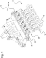
- the Figure 1 shows an agricultural soil cultivation machine 10 (can also be referred to as a carrier vehicle), which is mounted on a towing vehicle, not shown here, for example in the form of a tractor.
- the agricultural soil cultivation machine 10 comprises corresponding devices on the front side in order to be able to be coupled to a three-point suspension of the towing vehicle at the rear.
- the soil cultivation machine 10 comprises a multiplicity of soil cultivation devices 12, which are arranged transversely to the working direction of the carrier vehicle or the soil cultivation machine 10.
- the soil cultivation device 12 shown comprises in each case at least one coulter frame 14 adjustable in height or mounted at a defined height on the carrier vehicle (here soil tillage machine 10).
- a chopping and / or sowing coulter 16 is assigned to the coulter frame 14, which coulter frame 14 carries a depth guide roller 18 which is attached to a bracket 20 is mounted at a defined height with respect to the chopping and / or sowing coulter 16 or adjustable in height to this.
- the chopping and / or sowing coulter 16 is fixedly, for example frictionally, assigned to the coulter frame 14.
- the hoe and / or seed coulter 16 is mounted on the coulter frame 14 by means of a screw connection.
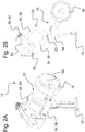
- the depth control roller 18 is via the holder 20 in relation to a working direction of the carrier vehicle 10 and the soil cultivation device 12 in front of the hoe and / or seed coulter 16 (cf. Figure 3 ) or behind the hoe and / or seed coulter 16 (cf. Figures 2 ) can be arranged.
- the bracket 20 is also coupled to the coulter frame 20 by means of a non-positive connection.
- the depth control roller 18 is arranged over the holder 20 in the working direction of the soil cultivating machine 10 behind the coulter 16.
- Such an embodiment of the soil cultivation device 12 is particularly suitable for sowing agricultural goods such as seeds, fertilizer or the like.
- the depth guide roller 18 is used in particular to define and maintain an exact or desired working depth of the seed coulter 16 and to define and maintain an exact placement depth of agricultural distribution material.
- the agricultural spreadable material can be pressed into the arable soil by means of the depth guide roller 18 arranged downstream of the seed coulter 16.
- a seed line (not shown here) is assigned to it, which can be fed with seed from a tank.
- the depth control roller 18 is arranged over the holder 20 in the working direction of the soil cultivating machine 10 in front of the hoe 16.
- Such an embodiment of the soil cultivation device 12 is particularly suitable for mechanical weed control.
- the mechanical weed control it is important that the grasses or weeds or the like uprooted by means of the hoe share 16 rest on top of the loosened soil so that they can dry up there. This can be achieved by a depth guide roller 18 arranged upstream of the chopping share 16.
- the suspension of the coulter frame 14 with the chopping and / or sowing coulter 16 provided thereon on the soil cultivating machine 10 or on an intermediate carrier arranged there is also clear.
- the coulter frame 14, together with the chopping and / or sowing coulter 16 attached to it, is movably mounted on the carrier vehicle or on the soil cultivating machine 10 or on an intermediate support 22 with at least two approximately parallel, with respect to Working direction of the carrier vehicle and the soil cultivation device 12 towed links 24 mounted vertically movable.
- the four-bar suspension 22 can in particular be in the form of a parallelogram be designed, by means of which the chopping and / or sowing coulter 16 is mounted pivotably and preferably height adjustable on the coulter frame 14 of the carrier vehicle.
- the hacking and / or sowing coulter 16 itself can be adjusted in height relative to the coulter frame 14.
- the handle 17 of the chopping and / or sowing coulter 16 comprises a large number of spaced apart openings into which a screw connection can be inserted to fix the chopping and / or sowing coulter 16 on the coulter frame 14.
- the two towed links 24 in a working position of the soil cultivating device 12 enclose an angle between approximately 10 ° and approximately 80 ° to a horizontal.
- the two towed links 24 can also be divided into an upper link 26 and a lower link 28, the upper link 26 and the lower link 28 being arranged parallel to one another.
- the upper link 26 and the lower link 28 have the same length between their joint axes 23.
- the inclined arrangement of the two towed links 24 relative to the horizontal also has the effect that the upper link 26 and the lower link 28 are oriented in a working position from top front to bottom back, relative to a forward direction of the hoe and / or seed coulter 16. In this way, when it hits a stone or an obstacle or the like, the chopping and / or sowing coulter 16 can advantageously move both backwards and upwards.
- the depth control roller 18 can be fixed to the holder 20 by means of socket pins 30 and, in particular, can be removed from there and attached to it without tools, so that the depth control roller 18 can be exchanged quickly and without great effort during maintenance, wear or when the soil cultivation device 12 is being converted can be.
- the depth guide roller 18 is adjustable in its relative height to the holder 20 and / or to the coulter frame 14 of the chopping and / or sowing coulter 16 and can be fixed at this set height.
- the soil cultivating machine 10 comprises a suspension frame 32 on which the four-bar suspension 22 is movably mounted.
- the four-joint suspension 22, which is movably mounted on the suspension frame 32 of the soil cultivating machine 10 has the towed links 24 and the coulter frame 14, which is movably mounted on the links 24 with a chopping and / or Seed coulter 16 is adjustable transversely to a working direction of the soil cultivation machine 10 and / or transversely to a central longitudinal axis of the soil cultivation machine 10 or the soil cultivation device 12 in the horizontal direction.
- a rail system 34 is arranged between the suspension frame 32 attached to the soil tillage machine 10 and the four-bar linkage 22, with the aid of which the four-bar linkage suspension 22 with the coulter frame 14 mounted on it can be displaced transversely to the working direction of the tillage machine 10.
- the four-bar suspension 22 can be mounted at different positions on the rail system 34, in particular along the longitudinal direction of the rail system 34 and / or transversely to the working direction of the soil cultivation machine 10.
- the rail system 34 shown comprises a slide frame 36 and a guide frame 38, the four-bar suspensions 22 of the hoe and / or seed coulters 16 being mounted in particular on the slide frame 36.
- the slide frame 36 can be displaced with respect to the guide frame 38 by means of an actuator, not shown here, for example in the form of a hydraulic and / or pneumatic cylinder. This can take place, for example, during or before a field trip.
- an actuator not shown here, for example in the form of a hydraulic and / or pneumatic cylinder. This can take place, for example, during or before a field trip.
- the rail system 34 has proven to be particularly advantageous in that the chopping and / or sowing coulters 16 can each be shifted into a position required for the respective work to be carried out by means of the chopping and / or sowing coulters 16. For example, a hoe 16 for mechanical weed control can be moved into a position between two rows of seeds 58 by means of the rail system 34.
- the rail system 34 can make it possible for the coulters 16 to be brought and / or displaced into a desired position for sowing for sowing agricultural goods.
- a controllable actuator 40 between at least one of the towed links 24 and the suspension frame 32 to apply a variable preload and / or restoring force and / or to the link 24 arranged to adjust the angle of the handlebars relative to the suspension frame 32 and thus to adjust the height of the coulter frame 14. That is to say, the actuator 40 is designed in such a way as to move the chopping and / or sowing coulter 16 into a raised transport position.
- the actuator 40 should be designed in such a way that by means of it the hoe and / or seed coulter can be pressed with a defined and / or definable force against a field and / or with a so-called defined and / or definable coulter pressure along a field.
- the actuator 40 can be designed differently depending on the embodiment.
- the actuator 40 is designed as a double-acting hydraulic cylinder 42.
- the hydraulic cylinder 42 has at least one chamber which can be acted upon by variable pressure, in particular for generating a variable preload force.
- the hydraulic cylinder 42 has two chambers that can be acted upon by variable pressures, each of which can be controlled differently, in particular to generate a variable pretensioning force and to lift out the chopping and / or sowing coulter 16.
- the chopping and / or sowing coulter 16 can be used as desired Working depth can be adjusted in terms of the prevailing soil conditions and working and / or spreading depth and in its excavation movement.
- valve V is part of a valve of the hydraulic cylinder 42 or that the valve V is integrated in the hydraulic cylinder 42. That is, the valve V and the hydraulic cylinder 42 can comprise a common housing.
- FIG. 4 a hydraulic circuit diagram for controlling the actuators 40, 40 ', in particular the hydraulic cylinders 42, 42' is shown, a control device not shown here being provided for controlling the actuators 40, 40 '.
- a control device not shown here being provided for controlling the actuators 40, 40 '.
- Both hydraulic cylinders 42, 42 'each include a piston side 44, 44' with a piston space 46, 46 ', a piston rod 48, 48' and a ring side 50, 50 '. While a first pressure line 52, 52 'each adjoins the piston side 44, 44', a second pressure line 54, 54 'adjoins the ring side 50, 50'.
- the piston sides 44, 44 'of the two hydraulic cylinders 42, 42' are each connected to a common pressure control valve 56 via a first pressure line 52, 52 '. Due to the connection shown with the pressure control valve 56, the means of the Hydraulic cylinder 42 on the chopping and / or sowing coulter 16 generated force can be limited or regulated. In addition to the pressure regulating valve 56, various other pressure limiting valves or similar means would also be conceivable. By means of the pressure regulating valve 56 it is possible to control and / or regulate the pressure and thus also the coulter pressure to a defined value as a function of the cylinder size. For example, the pressure can be controlled and / or regulated to a value between 5 bar and 20 bar. An embodiment variant with manual setting by an operator would also be conceivable or usable.
- each hydraulic cylinder 42, 42 ' is assigned a valve V 1 , V 2 , the valve being a "two-flow-path valve".
- the hydraulic cylinders 42, 42 ' are each connected to the valve V 1 , V 2 via the first pressure line 52, 52' and the second pressure line 54, 54 '. Since each hydraulic cylinder 42, 42 'is connected to a separate valve V 1 , V 2 , each hydraulic cylinder 42, 42' and thus each hoe and / or seed coulter 16 can be controlled independently of one another and thus pivoted or swiveled between a raised and a lowered position movable.
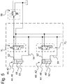
- FIG. 5 Another embodiment of a hydraulic circuit diagram for controlling the actuators 40, 40 ', in particular the hydraulic cylinders 42, 42', is shown, with a control device not shown here being provided for controlling the actuators 40, 40 '.
- a control device not shown here being provided for controlling the actuators 40, 40 '.
- the first pressure line 54, 54 'and the second pressure line 54, 54' of the two hydraulic cylinders 42, 42 ' are connected to a common pressure control valve 56 and can therefore be controlled and / or acted upon by means of a pressure that can be predetermined or defined by the pressure control valve 56. Because of this, both sides of the hydraulic cylinders 42, 42 'can be controlled with a definable pressure, the force required to generate a coulter pressure being achieved on the basis of the area difference between the piston side 44, 44' and the ring side 50, 50 '. This difference in area is determined as a function of the cylinder used in each case, so that in turn a defined coulter pressure can be controlled and / or regulated.
- two hydraulic cylinders 42, 42 ' are each assigned a valve V 1 , V 2 .
- the hydraulic cylinders 42, 42 ' are each connected to the valve V in particular via the first pressure line 52, 52'.
- Each hydraulic cylinder 42, 42 ' is connected to a separate valve V 1 , V 2 , consequently each hydraulic cylinder 42, 42' and thus each hoe and / or seed coulter 16 can be controlled independently of one another and thus pivoted between a raised and a lowered position or movable.
- Hydraulic circuit diagrams shown for each hoe and / or seed coulter 16 in particular each individual hydraulic cylinder 42, 42 'by means of which valves V 1 , V 2 can be actuated individually, such a hydraulic circuit diagram is also particularly suitable for section control applications. That is, the chopping and / or sowing coulter 16 can be pivoted between a raised and a lowered position independently of one another.
- FIG. 6 a further embodiment of a hydraulic circuit diagram for controlling the actuators 40, 40 ', in particular the hydraulic cylinders 42, 42', is shown, a control device not shown here being provided for controlling the actuators 40.
- a control device not shown here being provided for controlling the actuators 40.
- the in Figure 6 The hydraulic circuit diagram shown basically corresponds to that in Figure 5 shown hydraulic circuit diagram, but with the difference that in each case at least two hydraulic cylinders 42, 42 'and thus at least two hoe and / or seed coulters 16 are controlled and / or regulated by means of a common valve V.
- the first pressure line 52, 52 'of the two hydraulic cylinders 42, 42' are connected to a common valve V and to a common pressure regulating valve 56.
- costs can be saved, but a single row connection of the hoe and / or seed coulters 16 is no longer possible. Instead, several hydraulic cylinders 42, 42 'and thus sections of hoe and / or seed coulters 16 can be controlled simultaneously.
- valve V can form a structural unit with one of the hydraulic cylinders 42, 42'.
- valve V can open be mounted on a frame of the soil cultivation machine 10 and establish a connection to the hoe and / or seed coulter 16 associated cylinder by means of connecting lines.
- the control device can, for example, be equipped with a corresponding pressure sensor system (not shown here). It would also be possible for a sensor system to be attached to at least one chopping and / or sowing coulter 16 for detecting a force acting on the chopping and / or sowing coulter 16 and / or the depth guide roller 18.
- an activation, in particular coulter pressure regulation is automatically regulated and / or controlled as a function of a determined force.
- an operator only needs to define a setpoint and / or a setpoint depth and then the regulation takes place automatically.
- the hydraulic cylinders 42 are each directly connected to one another, that is, the one connecting line between two chopping and / or seed coulters 16 or hydraulic cylinders 42 associated with the chopping and / or seed coulters 16 are provided and the connecting lines do not have to be routed back to the frame of the soil tillage machine 10.
- the function and mode of operation of the rail system 34 clearly emerges, which is arranged between the suspension frame 32 attached to the soil cultivation machine 10 and the four-bar suspension 22.
- the four-joint suspension 22 with the coulter frame 14 mounted on it can be displaced transversely to the working direction of the tillage machine 10 so that the hoe and / or seed coulters 16 can be brought into the respective position required for the work to be performed.
- the hoe share 16 and the depth control roller 18 are in accordance with Figure 3 formed, according to which the depth control roller 18 is arranged in front of the hoe 16 in relation to a working direction of the soil cultivation machine 10 and the soil cultivation device 12.
- Figure 7B are the hoe and / or seed coulters 16 (here only seed coulters) in contrast to Figure 7A has been brought and / or shifted by means of the rail system 34 into a position desired for sowing, so that the seed can be deposited exactly in a desired row of seeds by means of the coulter 16.
- the hoe share 16 and the depth control roller 18 are according to the Figures 2 formed, after which the depth control roller 18 is arranged behind the coulter 16 in relation to a working direction of the soil cultivating machine 10 and the soil cultivating device 12.
- the hoe and / or seed coulters 16 can be or have been displaced into a so-called offset position by means of the rail system 34. That is to say, the hoe and / or seed coulters 16 have been shifted, for example, by half a line spacing to the left or right with respect to a centrally symmetrical position.
- the offset can thus be selected such that the hoe and / or seed coulters 16 can be or are moved essentially exactly between two rows of seeds, depending on the offset.
- the respective offset and / or central symmetrical position can be changed or can be changed depending on the working direction or travel direction of the soil cultivating machine 10, so that, for example, a seamless connection can be achieved.
- a left offset value is approached in one direction of travel and a right offset value is approached in the opposite direction of travel.
Landscapes
- Life Sciences & Earth Sciences (AREA)
- Engineering & Computer Science (AREA)
- Mechanical Engineering (AREA)
- Soil Sciences (AREA)
- Environmental Sciences (AREA)
- Zoology (AREA)
- Soil Working Implements (AREA)
- Sowing (AREA)
- Agricultural Machines (AREA)
Applications Claiming Priority (1)
| Application Number | Priority Date | Filing Date | Title |
|---|---|---|---|
| DE102019122712.7A DE102019122712A1 (de) | 2019-08-23 | 2019-08-23 | Landwirtschaftliche Bodenbearbeitungsmaschine zur Bearbeitung von Reihenkulturen |
Publications (3)
| Publication Number | Publication Date |
|---|---|
| EP3782443A2 true EP3782443A2 (fr) | 2021-02-24 |
| EP3782443A3 EP3782443A3 (fr) | 2021-05-26 |
| EP3782443B1 EP3782443B1 (fr) | 2024-03-20 |
Family
ID=71661681
Family Applications (1)
| Application Number | Title | Priority Date | Filing Date |
|---|---|---|---|
| EP20186154.9A Active EP3782443B1 (fr) | 2019-08-23 | 2020-07-16 | Machine de traitement du sol agricole destinée au traitement des cultures sur rang |
Country Status (2)
| Country | Link |
|---|---|
| EP (1) | EP3782443B1 (fr) |
| DE (1) | DE102019122712A1 (fr) |
Families Citing this family (3)
| Publication number | Priority date | Publication date | Assignee | Title |
|---|---|---|---|---|
| DE102021132471A1 (de) | 2021-12-09 | 2023-06-15 | Horsch Maschinen Gmbh | Landwirtschaftliche Bodenbearbeitungseinrichtung mit Ausgabeeinrichtungen zur Ausgabe eines Ausgabemediums |
| DE102022104251A1 (de) | 2022-02-23 | 2023-08-24 | Horsch Maschinen Gmbh | Bodenbearbeitungsmaschine mit Verteilervorrichtung |
| BE1031606B1 (nl) * | 2023-05-11 | 2024-12-11 | Vanhoucke Machine Eng Bv | Landbouwinrichting |
Citations (1)
| Publication number | Priority date | Publication date | Assignee | Title |
|---|---|---|---|---|
| DE3616403A1 (de) | 1986-05-15 | 1987-11-19 | Niemeyer Gmbh & Co Kg Soehne | Maschine zur bodenbearbeitung |
Family Cites Families (8)
| Publication number | Priority date | Publication date | Assignee | Title |
|---|---|---|---|---|
| US3503456A (en) * | 1967-09-01 | 1970-03-31 | Caterpillar Tractor Co | Mounting linkage for rippers |
| SE529466C2 (sv) * | 2005-06-07 | 2007-08-14 | Lars Askling | Redskapsbärare |
| US7261048B1 (en) * | 2005-11-30 | 2007-08-28 | Bourgault Industries Ltd. | Parallel link trailing arm for seeders |
| JP5184859B2 (ja) * | 2007-10-18 | 2013-04-17 | ニューデルタ工業株式会社 | 管理機の尾輪 |
| DE102008008553A1 (de) * | 2008-02-12 | 2009-08-13 | Amazonen-Werke H. Dreyer Gmbh & Co. Kg | Sämaschine |
| DE102009044854A1 (de) * | 2009-12-10 | 2011-06-16 | Amazonen-Werke H. Dreyer Gmbh & Co. Kg | Sämaschine |
| SE539313C2 (sv) * | 2012-09-27 | 2017-06-27 | Askling Lars | Anordning för styrning av verktyg vid sådd och jordbearbetning |
| DE102016214169B4 (de) * | 2016-08-01 | 2022-10-13 | Horsch Maschinen Gmbh | Säeinheit und Sämaschine mit mehreren solcher Säeinheiten |
-
2019
- 2019-08-23 DE DE102019122712.7A patent/DE102019122712A1/de active Pending
-
2020
- 2020-07-16 EP EP20186154.9A patent/EP3782443B1/fr active Active
Patent Citations (1)
| Publication number | Priority date | Publication date | Assignee | Title |
|---|---|---|---|---|
| DE3616403A1 (de) | 1986-05-15 | 1987-11-19 | Niemeyer Gmbh & Co Kg Soehne | Maschine zur bodenbearbeitung |
Also Published As
| Publication number | Publication date |
|---|---|
| EP3782443A3 (fr) | 2021-05-26 |
| EP3782443B1 (fr) | 2024-03-20 |
| DE102019122712A1 (de) | 2021-02-25 |
Similar Documents
| Publication | Publication Date | Title |
|---|---|---|
| DE102019108987A1 (de) | Landwirtschaftliche Arbeitsmaschine mit großer Arbeitsbreite | |
| DE102013108229A1 (de) | Bodenbearbeitungsgerät mit Einrichtung zur Rückverfestigung | |
| DE102016115319A1 (de) | Bodenbearbeitungsmaschine | |
| EP3782443B1 (fr) | Machine de traitement du sol agricole destinée au traitement des cultures sur rang | |
| EP3556192B1 (fr) | Machine agricole de traitement du sol ainsi que procédé de traitement du sol | |
| DE102021107169B4 (de) | Bodenbearbeitungsgerät | |
| EP4104654B1 (fr) | Appareil de traitement du sol à protection hydraulique contre les surcharges | |
| EP2835043B1 (fr) | Semoir combiné agricole tracté et procédé de transfert d'un semoir combiné agricole d'une position de transport en position de travail et inversement | |
| DE102014223095B4 (de) | Kombination aus einem landwirtschaftlichen Zugfahrzeug und einer Direktsaat-Sämaschine | |
| EP3808163B1 (fr) | Scarificateur agricole | |
| EP2944170B1 (fr) | Épandeur agricole, en particulier semoir, et procédé de réglage en hauteur des socs | |
| EP3620038B1 (fr) | Cultivateur tracté | |
| EP3381253A1 (fr) | Engin agricole doté d'éléments de guidage en profondeur | |
| EP3679774A1 (fr) | Rotoculteur | |
| EP0640272B2 (fr) | Machine combinée pour le travail du sol | |
| WO2023151757A1 (fr) | Appareil de pivotement pour un dispositif agricole de travail du sol | |
| DE102020111545A1 (de) | Landwirtschaftliche Bodenbearbeitungsmaschine mit Aushubvorrichtung | |
| EP3698616A1 (fr) | Agencement de soc pourvu de rouleau de pression à régulation de la pression | |
| DE102019104755A1 (de) | Bodenbearbeitungsmaschine, insbesondere Hackgerät | |
| DE102014223843A1 (de) | Kombination aus einem landwirtschaftlichen Zugfahrzeug und einer Direktsaat-Sämaschine | |
| EP4298880B1 (fr) | Bras oscillant pour machine agricole | |
| EP3593611B1 (fr) | Machine agricole de traitement du sol | |
| EP1726199B1 (fr) | Attelage trois points pour un tracteur pour viticulture et/ou culture fruitère | |
| DE102024110362A1 (de) | Landwirtschaftliche Maschine | |
| EP4413837A2 (fr) | Appareil de travail du sol à largeur variable |
Legal Events
| Date | Code | Title | Description |
|---|---|---|---|
| PUAI | Public reference made under article 153(3) epc to a published international application that has entered the european phase |
Free format text: ORIGINAL CODE: 0009012 |
|
| STAA | Information on the status of an ep patent application or granted ep patent |
Free format text: STATUS: THE APPLICATION HAS BEEN PUBLISHED |
|
| AK | Designated contracting states |
Kind code of ref document: A2 Designated state(s): AL AT BE BG CH CY CZ DE DK EE ES FI FR GB GR HR HU IE IS IT LI LT LU LV MC MK MT NL NO PL PT RO RS SE SI SK SM TR |
|
| AX | Request for extension of the european patent |
Extension state: BA ME |
|
| RIC1 | Information provided on ipc code assigned before grant |
Ipc: A01B 73/04 20060101AFI20210126BHEP Ipc: A01B 63/00 20060101ALI20210126BHEP Ipc: A01B 63/16 20060101ALI20210126BHEP |
|
| PUAL | Search report despatched |
Free format text: ORIGINAL CODE: 0009013 |
|
| AK | Designated contracting states |
Kind code of ref document: A3 Designated state(s): AL AT BE BG CH CY CZ DE DK EE ES FI FR GB GR HR HU IE IS IT LI LT LU LV MC MK MT NL NO PL PT RO RS SE SI SK SM TR |
|
| RIC1 | Information provided on ipc code assigned before grant |
Ipc: A01B 73/04 20060101AFI20210420BHEP Ipc: A01B 63/00 20060101ALI20210420BHEP Ipc: A01B 63/16 20060101ALI20210420BHEP |
|
| STAA | Information on the status of an ep patent application or granted ep patent |
Free format text: STATUS: REQUEST FOR EXAMINATION WAS MADE |
|
| 17P | Request for examination filed |
Effective date: 20211124 |
|
| RBV | Designated contracting states (corrected) |
Designated state(s): AL AT BE BG CH CY CZ DE DK EE ES FI FR GB GR HR HU IE IS IT LI LT LU LV MC MK MT NL NO PL PT RO RS SE SI SK SM TR |
|
| GRAP | Despatch of communication of intention to grant a patent |
Free format text: ORIGINAL CODE: EPIDOSNIGR1 |
|
| STAA | Information on the status of an ep patent application or granted ep patent |
Free format text: STATUS: GRANT OF PATENT IS INTENDED |
|
| INTG | Intention to grant announced |
Effective date: 20231017 |
|
| GRAS | Grant fee paid |
Free format text: ORIGINAL CODE: EPIDOSNIGR3 |
|
| GRAA | (expected) grant |
Free format text: ORIGINAL CODE: 0009210 |
|
| STAA | Information on the status of an ep patent application or granted ep patent |
Free format text: STATUS: THE PATENT HAS BEEN GRANTED |
|
| P01 | Opt-out of the competence of the unified patent court (upc) registered |
Effective date: 20240207 |
|
| AK | Designated contracting states |
Kind code of ref document: B1 Designated state(s): AL AT BE BG CH CY CZ DE DK EE ES FI FR GB GR HR HU IE IS IT LI LT LU LV MC MK MT NL NO PL PT RO RS SE SI SK SM TR |
|
| REG | Reference to a national code |
Ref country code: GB Ref legal event code: FG4D Free format text: NOT ENGLISH |
|
| REG | Reference to a national code |
Ref country code: CH Ref legal event code: EP |
|
| REG | Reference to a national code |
Ref country code: IE Ref legal event code: FG4D Free format text: LANGUAGE OF EP DOCUMENT: GERMAN |
|
| REG | Reference to a national code |
Ref country code: DE Ref legal event code: R096 Ref document number: 502020007384 Country of ref document: DE |
|
| PG25 | Lapsed in a contracting state [announced via postgrant information from national office to epo] |
Ref country code: LT Free format text: LAPSE BECAUSE OF FAILURE TO SUBMIT A TRANSLATION OF THE DESCRIPTION OR TO PAY THE FEE WITHIN THE PRESCRIBED TIME-LIMIT Effective date: 20240320 |
|
| REG | Reference to a national code |
Ref country code: LT Ref legal event code: MG9D |
|
| PG25 | Lapsed in a contracting state [announced via postgrant information from national office to epo] |
Ref country code: GR Free format text: LAPSE BECAUSE OF FAILURE TO SUBMIT A TRANSLATION OF THE DESCRIPTION OR TO PAY THE FEE WITHIN THE PRESCRIBED TIME-LIMIT Effective date: 20240621 |
|
| PG25 | Lapsed in a contracting state [announced via postgrant information from national office to epo] |
Ref country code: HR Free format text: LAPSE BECAUSE OF FAILURE TO SUBMIT A TRANSLATION OF THE DESCRIPTION OR TO PAY THE FEE WITHIN THE PRESCRIBED TIME-LIMIT Effective date: 20240320 Ref country code: RS Free format text: LAPSE BECAUSE OF FAILURE TO SUBMIT A TRANSLATION OF THE DESCRIPTION OR TO PAY THE FEE WITHIN THE PRESCRIBED TIME-LIMIT Effective date: 20240620 |
|
| REG | Reference to a national code |
Ref country code: NL Ref legal event code: MP Effective date: 20240320 |
|
| PG25 | Lapsed in a contracting state [announced via postgrant information from national office to epo] |
Ref country code: RS Free format text: LAPSE BECAUSE OF FAILURE TO SUBMIT A TRANSLATION OF THE DESCRIPTION OR TO PAY THE FEE WITHIN THE PRESCRIBED TIME-LIMIT Effective date: 20240620 Ref country code: NO Free format text: LAPSE BECAUSE OF FAILURE TO SUBMIT A TRANSLATION OF THE DESCRIPTION OR TO PAY THE FEE WITHIN THE PRESCRIBED TIME-LIMIT Effective date: 20240620 Ref country code: LT Free format text: LAPSE BECAUSE OF FAILURE TO SUBMIT A TRANSLATION OF THE DESCRIPTION OR TO PAY THE FEE WITHIN THE PRESCRIBED TIME-LIMIT Effective date: 20240320 Ref country code: HR Free format text: LAPSE BECAUSE OF FAILURE TO SUBMIT A TRANSLATION OF THE DESCRIPTION OR TO PAY THE FEE WITHIN THE PRESCRIBED TIME-LIMIT Effective date: 20240320 Ref country code: GR Free format text: LAPSE BECAUSE OF FAILURE TO SUBMIT A TRANSLATION OF THE DESCRIPTION OR TO PAY THE FEE WITHIN THE PRESCRIBED TIME-LIMIT Effective date: 20240621 Ref country code: FI Free format text: LAPSE BECAUSE OF FAILURE TO SUBMIT A TRANSLATION OF THE DESCRIPTION OR TO PAY THE FEE WITHIN THE PRESCRIBED TIME-LIMIT Effective date: 20240320 Ref country code: BG Free format text: LAPSE BECAUSE OF FAILURE TO SUBMIT A TRANSLATION OF THE DESCRIPTION OR TO PAY THE FEE WITHIN THE PRESCRIBED TIME-LIMIT Effective date: 20240320 |
|
| PG25 | Lapsed in a contracting state [announced via postgrant information from national office to epo] |
Ref country code: SE Free format text: LAPSE BECAUSE OF FAILURE TO SUBMIT A TRANSLATION OF THE DESCRIPTION OR TO PAY THE FEE WITHIN THE PRESCRIBED TIME-LIMIT Effective date: 20240320 Ref country code: LV Free format text: LAPSE BECAUSE OF FAILURE TO SUBMIT A TRANSLATION OF THE DESCRIPTION OR TO PAY THE FEE WITHIN THE PRESCRIBED TIME-LIMIT Effective date: 20240320 |
|
| PG25 | Lapsed in a contracting state [announced via postgrant information from national office to epo] |
Ref country code: NL Free format text: LAPSE BECAUSE OF FAILURE TO SUBMIT A TRANSLATION OF THE DESCRIPTION OR TO PAY THE FEE WITHIN THE PRESCRIBED TIME-LIMIT Effective date: 20240320 |
|
| PG25 | Lapsed in a contracting state [announced via postgrant information from national office to epo] |
Ref country code: NL Free format text: LAPSE BECAUSE OF FAILURE TO SUBMIT A TRANSLATION OF THE DESCRIPTION OR TO PAY THE FEE WITHIN THE PRESCRIBED TIME-LIMIT Effective date: 20240320 |
|
| PG25 | Lapsed in a contracting state [announced via postgrant information from national office to epo] |
Ref country code: IS Free format text: LAPSE BECAUSE OF FAILURE TO SUBMIT A TRANSLATION OF THE DESCRIPTION OR TO PAY THE FEE WITHIN THE PRESCRIBED TIME-LIMIT Effective date: 20240720 |
|
| PG25 | Lapsed in a contracting state [announced via postgrant information from national office to epo] |
Ref country code: SM Free format text: LAPSE BECAUSE OF FAILURE TO SUBMIT A TRANSLATION OF THE DESCRIPTION OR TO PAY THE FEE WITHIN THE PRESCRIBED TIME-LIMIT Effective date: 20240320 Ref country code: PT Free format text: LAPSE BECAUSE OF FAILURE TO SUBMIT A TRANSLATION OF THE DESCRIPTION OR TO PAY THE FEE WITHIN THE PRESCRIBED TIME-LIMIT Effective date: 20240722 |
|
| PG25 | Lapsed in a contracting state [announced via postgrant information from national office to epo] |
Ref country code: ES Free format text: LAPSE BECAUSE OF FAILURE TO SUBMIT A TRANSLATION OF THE DESCRIPTION OR TO PAY THE FEE WITHIN THE PRESCRIBED TIME-LIMIT Effective date: 20240320 |
|
| PG25 | Lapsed in a contracting state [announced via postgrant information from national office to epo] |
Ref country code: EE Free format text: LAPSE BECAUSE OF FAILURE TO SUBMIT A TRANSLATION OF THE DESCRIPTION OR TO PAY THE FEE WITHIN THE PRESCRIBED TIME-LIMIT Effective date: 20240320 |
|
| PG25 | Lapsed in a contracting state [announced via postgrant information from national office to epo] |
Ref country code: PL Free format text: LAPSE BECAUSE OF FAILURE TO SUBMIT A TRANSLATION OF THE DESCRIPTION OR TO PAY THE FEE WITHIN THE PRESCRIBED TIME-LIMIT Effective date: 20240320 |
|
| PG25 | Lapsed in a contracting state [announced via postgrant information from national office to epo] |
Ref country code: SK Free format text: LAPSE BECAUSE OF FAILURE TO SUBMIT A TRANSLATION OF THE DESCRIPTION OR TO PAY THE FEE WITHIN THE PRESCRIBED TIME-LIMIT Effective date: 20240320 |
|
| PG25 | Lapsed in a contracting state [announced via postgrant information from national office to epo] |
Ref country code: SM Free format text: LAPSE BECAUSE OF FAILURE TO SUBMIT A TRANSLATION OF THE DESCRIPTION OR TO PAY THE FEE WITHIN THE PRESCRIBED TIME-LIMIT Effective date: 20240320 Ref country code: SK Free format text: LAPSE BECAUSE OF FAILURE TO SUBMIT A TRANSLATION OF THE DESCRIPTION OR TO PAY THE FEE WITHIN THE PRESCRIBED TIME-LIMIT Effective date: 20240320 Ref country code: RO Free format text: LAPSE BECAUSE OF FAILURE TO SUBMIT A TRANSLATION OF THE DESCRIPTION OR TO PAY THE FEE WITHIN THE PRESCRIBED TIME-LIMIT Effective date: 20240320 Ref country code: PT Free format text: LAPSE BECAUSE OF FAILURE TO SUBMIT A TRANSLATION OF THE DESCRIPTION OR TO PAY THE FEE WITHIN THE PRESCRIBED TIME-LIMIT Effective date: 20240722 Ref country code: PL Free format text: LAPSE BECAUSE OF FAILURE TO SUBMIT A TRANSLATION OF THE DESCRIPTION OR TO PAY THE FEE WITHIN THE PRESCRIBED TIME-LIMIT Effective date: 20240320 Ref country code: IS Free format text: LAPSE BECAUSE OF FAILURE TO SUBMIT A TRANSLATION OF THE DESCRIPTION OR TO PAY THE FEE WITHIN THE PRESCRIBED TIME-LIMIT Effective date: 20240720 Ref country code: ES Free format text: LAPSE BECAUSE OF FAILURE TO SUBMIT A TRANSLATION OF THE DESCRIPTION OR TO PAY THE FEE WITHIN THE PRESCRIBED TIME-LIMIT Effective date: 20240320 Ref country code: EE Free format text: LAPSE BECAUSE OF FAILURE TO SUBMIT A TRANSLATION OF THE DESCRIPTION OR TO PAY THE FEE WITHIN THE PRESCRIBED TIME-LIMIT Effective date: 20240320 |
|
| REG | Reference to a national code |
Ref country code: DE Ref legal event code: R082 Ref document number: 502020007384 Country of ref document: DE Representative=s name: BENNINGER, JOHANNES, DIPL.-ING., DE |
|
| PG25 | Lapsed in a contracting state [announced via postgrant information from national office to epo] |
Ref country code: IT Free format text: LAPSE BECAUSE OF FAILURE TO SUBMIT A TRANSLATION OF THE DESCRIPTION OR TO PAY THE FEE WITHIN THE PRESCRIBED TIME-LIMIT Effective date: 20240320 |
|
| REG | Reference to a national code |
Ref country code: DE Ref legal event code: R097 Ref document number: 502020007384 Country of ref document: DE |
|
| PG25 | Lapsed in a contracting state [announced via postgrant information from national office to epo] |
Ref country code: IT Free format text: LAPSE BECAUSE OF FAILURE TO SUBMIT A TRANSLATION OF THE DESCRIPTION OR TO PAY THE FEE WITHIN THE PRESCRIBED TIME-LIMIT Effective date: 20240320 |
|
| PG25 | Lapsed in a contracting state [announced via postgrant information from national office to epo] |
Ref country code: DK Free format text: LAPSE BECAUSE OF FAILURE TO SUBMIT A TRANSLATION OF THE DESCRIPTION OR TO PAY THE FEE WITHIN THE PRESCRIBED TIME-LIMIT Effective date: 20240320 |
|
| PLBE | No opposition filed within time limit |
Free format text: ORIGINAL CODE: 0009261 |
|
| STAA | Information on the status of an ep patent application or granted ep patent |
Free format text: STATUS: NO OPPOSITION FILED WITHIN TIME LIMIT |
|
| PG25 | Lapsed in a contracting state [announced via postgrant information from national office to epo] |
Ref country code: DK Free format text: LAPSE BECAUSE OF FAILURE TO SUBMIT A TRANSLATION OF THE DESCRIPTION OR TO PAY THE FEE WITHIN THE PRESCRIBED TIME-LIMIT Effective date: 20240320 |
|
| PG25 | Lapsed in a contracting state [announced via postgrant information from national office to epo] |
Ref country code: MC Free format text: LAPSE BECAUSE OF FAILURE TO SUBMIT A TRANSLATION OF THE DESCRIPTION OR TO PAY THE FEE WITHIN THE PRESCRIBED TIME-LIMIT Effective date: 20240320 |
|
| 26N | No opposition filed |
Effective date: 20241223 |
|
| REG | Reference to a national code |
Ref country code: CH Ref legal event code: PL |
|
| PG25 | Lapsed in a contracting state [announced via postgrant information from national office to epo] |
Ref country code: LU Free format text: LAPSE BECAUSE OF NON-PAYMENT OF DUE FEES Effective date: 20240716 |
|
| GBPC | Gb: european patent ceased through non-payment of renewal fee |
Effective date: 20240716 |
|
| PG25 | Lapsed in a contracting state [announced via postgrant information from national office to epo] |
Ref country code: LU Free format text: LAPSE BECAUSE OF NON-PAYMENT OF DUE FEES Effective date: 20240716 |
|
| PG25 | Lapsed in a contracting state [announced via postgrant information from national office to epo] |
Ref country code: SI Free format text: LAPSE BECAUSE OF FAILURE TO SUBMIT A TRANSLATION OF THE DESCRIPTION OR TO PAY THE FEE WITHIN THE PRESCRIBED TIME-LIMIT Effective date: 20240320 Ref country code: BE Free format text: LAPSE BECAUSE OF NON-PAYMENT OF DUE FEES Effective date: 20240731 Ref country code: CH Free format text: LAPSE BECAUSE OF NON-PAYMENT OF DUE FEES Effective date: 20240731 |
|
| PG25 | Lapsed in a contracting state [announced via postgrant information from national office to epo] |
Ref country code: GB Free format text: LAPSE BECAUSE OF NON-PAYMENT OF DUE FEES Effective date: 20240716 |
|
| REG | Reference to a national code |
Ref country code: BE Ref legal event code: MM Effective date: 20240731 |
|
| PG25 | Lapsed in a contracting state [announced via postgrant information from national office to epo] |
Ref country code: IE Free format text: LAPSE BECAUSE OF NON-PAYMENT OF DUE FEES Effective date: 20240716 |
|
| PGFP | Annual fee paid to national office [announced via postgrant information from national office to epo] |
Ref country code: DE Payment date: 20250722 Year of fee payment: 6 |
|
| PGFP | Annual fee paid to national office [announced via postgrant information from national office to epo] |
Ref country code: FR Payment date: 20250723 Year of fee payment: 6 Ref country code: AT Payment date: 20251020 Year of fee payment: 5 |
|
| PGFP | Annual fee paid to national office [announced via postgrant information from national office to epo] |
Ref country code: CZ Payment date: 20250703 Year of fee payment: 6 |
|
| PG25 | Lapsed in a contracting state [announced via postgrant information from national office to epo] |
Ref country code: CY Free format text: LAPSE BECAUSE OF FAILURE TO SUBMIT A TRANSLATION OF THE DESCRIPTION OR TO PAY THE FEE WITHIN THE PRESCRIBED TIME-LIMIT; INVALID AB INITIO Effective date: 20200716 |
|
| PG25 | Lapsed in a contracting state [announced via postgrant information from national office to epo] |
Ref country code: HU Free format text: LAPSE BECAUSE OF FAILURE TO SUBMIT A TRANSLATION OF THE DESCRIPTION OR TO PAY THE FEE WITHIN THE PRESCRIBED TIME-LIMIT; INVALID AB INITIO Effective date: 20200716 |