EP3782533B1 - Reprocesseur d'endoscope - Google Patents
Reprocesseur d'endoscope Download PDFInfo
- Publication number
- EP3782533B1 EP3782533B1 EP19789459.5A EP19789459A EP3782533B1 EP 3782533 B1 EP3782533 B1 EP 3782533B1 EP 19789459 A EP19789459 A EP 19789459A EP 3782533 B1 EP3782533 B1 EP 3782533B1
- Authority
- EP
- European Patent Office
- Prior art keywords
- terminal
- unit
- observation
- top cover
- holding unit
- Prior art date
- Legal status (The legal status is an assumption and is not a legal conclusion. Google has not performed a legal analysis and makes no representation as to the accuracy of the status listed.)
- Active
Links
Images







Classifications
-
- A—HUMAN NECESSITIES
- A61—MEDICAL OR VETERINARY SCIENCE; HYGIENE
- A61B—DIAGNOSIS; SURGERY; IDENTIFICATION
- A61B1/00—Instruments for performing medical examinations of the interior of cavities or tubes of the body by visual or photographical inspection, e.g. endoscopes; Illuminating arrangements therefor
- A61B1/12—Instruments for performing medical examinations of the interior of cavities or tubes of the body by visual or photographical inspection, e.g. endoscopes; Illuminating arrangements therefor with cooling or rinsing arrangements
- A61B1/121—Instruments for performing medical examinations of the interior of cavities or tubes of the body by visual or photographical inspection, e.g. endoscopes; Illuminating arrangements therefor with cooling or rinsing arrangements provided with means for cleaning post-use
- A61B1/123—Instruments for performing medical examinations of the interior of cavities or tubes of the body by visual or photographical inspection, e.g. endoscopes; Illuminating arrangements therefor with cooling or rinsing arrangements provided with means for cleaning post-use using washing machines
-
- A—HUMAN NECESSITIES
- A61—MEDICAL OR VETERINARY SCIENCE; HYGIENE
- A61B—DIAGNOSIS; SURGERY; IDENTIFICATION
- A61B1/00—Instruments for performing medical examinations of the interior of cavities or tubes of the body by visual or photographical inspection, e.g. endoscopes; Illuminating arrangements therefor
- A61B1/00002—Operational features of endoscopes
- A61B1/00004—Operational features of endoscopes characterised by electronic signal processing
- A61B1/00006—Operational features of endoscopes characterised by electronic signal processing of control signals
-
- A—HUMAN NECESSITIES
- A61—MEDICAL OR VETERINARY SCIENCE; HYGIENE
- A61B—DIAGNOSIS; SURGERY; IDENTIFICATION
- A61B1/00—Instruments for performing medical examinations of the interior of cavities or tubes of the body by visual or photographical inspection, e.g. endoscopes; Illuminating arrangements therefor
- A61B1/00002—Operational features of endoscopes
- A61B1/00011—Operational features of endoscopes characterised by signal transmission
-
- A—HUMAN NECESSITIES
- A61—MEDICAL OR VETERINARY SCIENCE; HYGIENE
- A61B—DIAGNOSIS; SURGERY; IDENTIFICATION
- A61B1/00—Instruments for performing medical examinations of the interior of cavities or tubes of the body by visual or photographical inspection, e.g. endoscopes; Illuminating arrangements therefor
- A61B1/00002—Operational features of endoscopes
- A61B1/00043—Operational features of endoscopes provided with output arrangements
- A61B1/00045—Display arrangement
- A61B1/00048—Constructional features of the display
-
- A—HUMAN NECESSITIES
- A61—MEDICAL OR VETERINARY SCIENCE; HYGIENE
- A61B—DIAGNOSIS; SURGERY; IDENTIFICATION
- A61B90/00—Instruments, implements or accessories specially adapted for surgery or diagnosis and not covered by any of the groups A61B1/00 - A61B50/00, e.g. for luxation treatment or for protecting wound edges
- A61B90/70—Cleaning devices specially adapted for surgical instruments
- A61B2090/701—Cleaning devices specially adapted for surgical instruments for flexible tubular instruments, e.g. endoscopes
Definitions
- the present invention relates to an endoscope reprocessor.
- endoscope reprocessors have been used that perform reprocessing, such as cleaning and disinfecting, on an endoscope used on a subject.
- reprocessing such as cleaning and disinfecting
- the endoscope reprocessor to adopt a technique to determine whether or not the endoscope reprocessor is being used with an endoscope being appropriately disposed.
- JP 2002-272684 A discloses an endoscope cleaning device where the inside of a cleaning tank is irradiated with ultrasound to detect ultrasound reflection information and, thereafter, it is possible to determine whether or not an endoscope is appropriately disposed based on the ultrasound reflection information and RFID information.
- DE 10 2013 202 540 A1 discloses a reprocessing device for cleaning and/or disinfecting surgical instruments, i.e. endoscopes, having fluid connectors connected with surgical instrument.
- JP 2013-135935 A discloses an endoscope cleaning and disinfecting apparatus for automatically cleaning and disinfecting an object to be cleaned.
- the present invention has been made in view of the above, and it is an object of the present invention to provide an endoscope reprocessor that can be more easily equipped with an observation terminal, which determines whether or not the endoscope reprocessor is being used in an appropriate use state.
- Fig. 1 is a perspective view of an endoscope reprocessor 1 according to a first embodiment of the present invention.
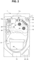
- Fig. 2 is a top plan view of the endoscope reprocessor 1 according to the first embodiment of the present invention.
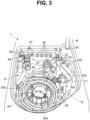
- Fig. 3 is an explanatory view for describing a state where an endoscope E is disposed in a treatment tank 31 of the endoscope reprocessor 1 according to the first embodiment of the present invention.
- the endoscope reprocessor 1 is a device that performs reprocessing on the contaminated endoscope E, and components or accessories of the endoscope E, or the like.
- reprocessing is not particularly limited, and may be any one of rinsing with water, cleaning to remove stains caused by organic matter or the like, disinfecting to make predetermined microorganisms inactive, sterilizing to eliminate or kill all microorganisms, or a combination of these.
- the endoscope reprocessor 1 may be used for performing reprocessing on tubular medical equipment, such as dilators or endoscope sheaths.
- a downward direction indicates a gravity direction
- an upward direction indicates a direction opposite to the gravity direction
- a high or a low indicates a height relationship along the gravity direction
- the endoscope reprocessor 1 includes a top cover 11, a reprocessor body 21, and a terminal holding unit 111.
- the top cover 11 has a cover panel 13, which acts as a transmitting unit.
- the terminal holding unit 111 is provided to the top cover 11.
- the terminal holding unit 111 holds an observation terminal D that receives visible light as an observation wave.
- the top cover 11 is disposed such that the back surface of the top cover 11 faces the treatment tank 31 of the reprocessor body 21.
- the top cover 11 opens and closes the treatment tank 31 by rotating about a hinge 11a.
- one end of the top cover 11 is connected to the reprocessor body 21 by the hinge 11a, and the other end of the top cover 11 rotates about the one end of the top cover 11.
- the top cover 11 includes a cover frame 12, the cover panel 13 being the transmitting unit, a gas filter 14, and a finger hooking portion 15.
- the cover frame 12 is made of a material, such as metal or a resin, and is provided to surround a periphery portion of the top cover 11.
- the cover frame 12 has a sealing 12a on a back surface of the cover frame 12, and the sealing 12a is provided to surround and extend along an upper edge portion of the treatment tank 31. When the top cover 11 is brought into the closed state, the sealing 12a is brought into close contact with the upper edge portion of the treatment tank 31.
- the cover panel 13 has light transmitting properties.
- An example of a transmitting material for forming the cover panel 13 may be a resin or ceramic.
- a resin may be polycarbonate having chemical resistance and visible light transmitting properties.
- the cover panel 13 is provided inside the cover frame 12.
- the configuration of the cover panel 13 is not particularly limited.
- the cover panel 13 may have a cover discharge port 13a at a portion close to the one end of the cover panel 13 and bulging into a dome shape.
- the gas filter 14 is formed of a filter medium accommodating container and a filter medium.
- the filter medium accommodating container is made of a material, such as a resin.
- the filter medium is accommodated in the filter medium accommodating container.
- the gas filter 14 is detachably attached to the cover discharge port 13a.
- the gas filter 14 has a filter discharge port 14a at an upper portion of the gas filter 14 ( Fig. 2 ).
- the gas filter 14 takes in a gas in the treatment tank 31 through the cover discharge port 13a, and discharges, through the filter discharge port 14a, the gas subjected to filtering for deodorizing or the like.
- the finger hooking portion 15 is made of a material, such as metal or a resin.
- the finger hooking portion 15 is continuously formed with the other end side of the cover frame 12 to allow a user to hook his/her finger on the finger hooking portion 15.
- a fastener 15a is provided inside the finger hooking portion 15.
- the reprocessor body 21 includes a locking unit 22, a display unit 23, an operation unit 24, a water supply hose connection port 25, a communication unit 26, a control unit 27 and the treatment tank 31.
- the locking unit 22 is provided on the other end side of an upper portion of the reprocessor body 21. Under the control of the control unit 27, the locking unit 22 engages with the fastener 15a or releases the engagement with the fastener 15a. When the locking unit 22 engages with the fastener 15a, the top cover 11 is locked in the closed state. It may be configured such that the locking unit 22 is linked with a foot panel 28 to allow the engagement of the locking unit 22 with the fastener 15a to be released in response to an operation of the foot panel.
- the display unit 23 is provided to a corner portion on the other end side of the upper portion of the reprocessor body 21.
- the display unit 23 includes a display panel, and is configured to display various notifications to a user under the control of the control unit 27.
- the operation unit 24 has an instruction input button to input various instructions to the endoscope reprocessor 1.
- the water supply hose connection port 25 is connected with a water faucet via a water supply tube W.
- the communication unit 26 is connected with the control unit 27, and is configured such that the communication unit 26 can communicate with the observation terminal D by wired or wireless communication under the control of the control unit 27. It may be configured such that the communication unit 26 can communicate with an external device via a network.
- the control unit 27 controls respective units in the endoscope reprocessor 1.
- the control unit 27 includes a processor and a memory, and can execute various programs stored in the memory. A function of the control unit 27 is achieved by reading and executing the program stored in the memory.
- the control unit 27 is connected with the observation terminal D via the communication unit 26.
- the control unit 27 receives an input of a determination result indicating an abnormality from the observation terminal D, the control unit 27 notifies a user of an abnormality.
- An abnormality notification may be a warning displayed on the display unit 23, or an output of a warning sound from a speaker not shown in the drawing. Further, when the control unit 27 receives the input of the determination result indicating an abnormality from the observation terminal D, the control unit 27 may perform a control to stop reprocessing.
- the treatment tank 31 is provided to the upper portion of the reprocessor body 21. As shown in Fig. 3 , when the top cover 11 is brought into an open state, the treatment tank 31 is exposed to the outside.
- the treatment tank 31 has a recessed shape to accommodate the endoscope E that performs reprocessing and to store a liquid, such as a cleaning solution, a disinfecting liquid or a rinsing liquid.
- the treatment tank 31 has air/water feeding connectors 32, a holding net 33, a cleaning casing 34, water level gauges 35, a medicinal solution nozzle 36, a water supply circulation nozzle 37, a circulation port 38, and a liquid discharge port 39.
- cleaning tubes T connect the reprocessor body 21 and the endoscope E with each other.
- Each cleaning tube T includes an endoscope-side connector T1 connected with the endoscope E, and a processor-side connector T2 connected with the reprocessor body 21.
- the reprocessor-side connector T2 has an ejection port T3 from which liquid ejects in a liquid passing state.
- the endoscope E includes, for example, an endoscope operation portion E1, an insertion portion E2, a universal cord E3, and a scope connector E4.
- the insertion portion E2 has an elongated shape that extends from the endoscope operation portion E1 toward a distal end side of the endoscope E.
- the universal cord E3 extends from the endoscope operation portion E1.
- the scope connector E4 is caused to extend from a distal end side of the universal cord E3.
- the endoscope-side connectors T1 are connected to the endoscope operation portion E1 and the scope connector E4.
- the air/water feeding connectors 32 are provided to a wall portion of the treatment tank 31.
- the reprocessor-side connectors T2 are connected to the air/water feeding connectors 32.
- Eight air/water feeding connectors 32 are shown in Fig. 3 . However, the number of air/water feeding connectors 32 is not limited to eight.
- the air/water feeding connectors 32 are connected with the circulation port 38 through conduits.
- the control unit 27 drives a circulation pump
- the air/water feeding connectors 32 takes in liquid through the circulation port 38, and feed the liquid to the endoscope E.
- the control unit 27 drives an air compressor
- the air/water feeding connectors 32 takes in air from the atmosphere, and feed the air to the endoscope E.
- the holding net 33 is made of a material, such as metal or a resin, and is attached to a bottom portion of the treatment tank 31.
- the holding net 33 includes an index pin 33a, an operation portion receiving portion 33b, a scope connector receiving portion 33c, and a hook 33d.
- the index pin 33a has a mark indicating a height of disinfecting liquid level.
- the operation portion receiving portion 33b is provided for disposing the endoscope operation portion E1.
- the scope connector receiving portion 33c is provided for disposing the scope connector E4.
- the hook 33d is provided for hooking the insertion portion E2 and the universal cord E3.
- a user disposes the endoscope operation portion E1 to the operation portion receiving portion 33b, disposes the scope connector E4 to the scope connector receiving portion 33c, and winds the insertion portion E2 and the universal cord E3 such that the insertion portion E2 and the universal cord E3 pass on the inside of the hook 33d.
- the user causes the endoscope E to be held by the holding net 33 such that the endoscope E is disposed below the mark on the index pin 33a to prevent the endoscope E from exceeding the disinfecting liquid level.
- the cleaning casing 34 is attached to a center portion of the holding net 33.
- Accessories removed from the endoscope E such as an air/water feeding button, a suction button, and a cap, are accommodated in the cleaning casing 34.
- a lower portion of the cleaning casing 34 is connected with a bottom portion connector provided to a bottom portion of the reprocessor body 21. Under the control of the control unit 27, air or water is fed to the cleaning casing 34 from the bottom portion connector.
- the accessories are not particularly limited. Examples of the accessories are the suction button, the air/water feeding button, and a distal end cover that covers a distal end portion of the endoscope E, which are mounted on the endoscope E during the use and removed from the endoscope E at the time of performing reprocessing.
- the water level gauges 35 measure a level of liquid in the cleaning tank, and outputs the measurement result to the control unit 27.
- the medicinal solution nozzle 36 is provided to a terrace portion provided at a position one step higher than other portions of a periphery portion in the treatment tank 31.
- the medicinal solution nozzle 36 is connected with a medicinal solution tank in the reprocessor body 21.
- the control unit 27 drives a medicinal solution pump, the medicinal solution nozzle 36 discharges medicinal solution in the medicinal solution tank into the treatment tank 31.
- the water supply circulation nozzle 37 is provided to the terrace portion.
- the water supply circulation nozzle 37 is connected with the circulation port 38 through a conduit.
- the control unit 27 drives the circulation pump, the water supply circulation nozzle 37 takes in liquid through the circulation port 38, and discharges the liquid into the treatment tank 31.
- the water supply circulation nozzle 37 also discharges, to the treatment tank 31, water supplied through the water supply tube W via the water supply hose connection port 25.
- Each of the circulation port 38 and the liquid discharge port 39 is formed on the bottom portion of the treatment tank 31, and a mesh filter is mounted on each of the circulation port 38 and the liquid discharge port 39 ( Fig. 2 ). Liquid is taken into the treatment tank 31 through the circulation port 38.
- the liquid discharge port 39 is connected with external liquid discharge means, and the liquid in the treatment tank 31 is discharged to the outside through the liquid discharge port 39. Further, the liquid discharge port 39 can be connected with the medicinal solution tank under the control of the control unit 27. In the case where the liquid discharge port 39 is connected with the medicinal solution tank, medicinal solution used in the treatment tank 31 is recovered into the medicinal solution tank.
- An example of medicinal solution used in the endoscope reprocessor 1 may be peracetic acid solution.
- Peracetic acid solution is prepared in the endoscope reprocessor 1 at a predetermined concentration in such a manner that a stock solution is diluted with water supplied through the water supply tube W.
- the medicinal solution is stored in the medicinal solution tank, and is discharged to the treatment tank 31 from the medicinal solution nozzle 36 at the time of disinfecting the endoscope E. After the medicinal solution is used for disinfecting the endoscope E, the medicinal solution is recovered into the medicinal solution tank so as to be used in the next reprocessing.
- a concentration of medicinal solution decreases with the number of use days and the number of use times.
- the medicinal solution may be prepared by the endoscope reprocessor 1.
- the terminal holding unit 111 is made of a material, such as metal or a resin, and is provided to a front surface side on a side opposite to the back surface side of the top cover 11 ( Fig. 2 ).
- the terminal holding unit 111 is configured such that the terminal holding unit 111 can hold the observation terminal D at a position that allows the observation terminal D to observe the inside of the treatment tank 31 through the cover panel 13. In other words, the terminal holding unit 111 is disposed on an outer surface of the top cover 11.
- Fig. 4 is a front view of the observation terminal D of the endoscope reprocessor 1 according to the first embodiment of the present invention.
- Fig. 5 is a back view of the observation terminal D of the endoscope reprocessor 1 according to the first embodiment of the present invention.
- the observation terminal D is a portable information terminal of a tablet type, for example.
- the observation terminal D includes cameras D1, D2, a control unit D3, a communication unit D4, a display unit D5 and an external connection connector D6.
- the camera D1 is provided to a front surface of the observation terminal D.
- the camera D2 is provided to a rear surface of the observation terminal D.
- the camera D1, D2 includes an image pickup device formed of a CMOS, a CCD or the like, picks up an image of the outside, and outputs the picked-up image to the control unit D3.
- the camera D1, D2 may include a wide angle lens. The wide angle lens may be fixed to the observation terminal D, or may be detachably mounted on the observation terminal D.
- the camera D1 which acts as a receiving unit, receives visible light reflected in the treatment tank 31 and transmitting through the cover panel 13.
- the control unit D3 includes a processor and a memory, and controls actions of respective units in the observation terminal D.
- the control unit D3 detects use state information from a picked-up image or a movie.
- Examples of the use state information may be a disposition state of the endoscope E, a connection state between the endoscope E and the reprocessor body 21, a waterproof state of the endoscope E, a mounting state of the mesh filter, a liquid passing state of the conduit, a driving state of the pump, and a concentration state of medicinal solution.
- the use state information may be all of or some of these states, or may be use state information indicating other use state.
- control unit D3 determines based on the detection result whether the use state information is normal or abnormal, and outputs the determination result.
- the communication unit D4 communicates with the communication unit 26, and outputs the determination result to the control unit 27.
- the display unit D5 can display various types of information on a display panel under the control of the control unit D3.
- the display unit D5 may display the determination result.
- a touch panel is made to overlap with the display panel, so that it is possible to input various instructions by touch operation.
- the external connection connector D6 is electrically connected with an external device.
- the endoscope reprocessor 1 includes the top cover 11 and at least one terminal holding unit 111.
- the top cover 11 is made of a material that allows light to transmit through the material, that is, a material having light transmitting properties, and the top cover 11 is disposed such that light is allowed to transmit from a reprocessor outer surface to the inside of the treatment tank 31.
- the terminal holding unit 111 is disposed on the reprocessor outer surface, and holds the observation terminal D at a position that allows the observation terminal D to observe the inside of the treatment tank 31 through the cover panel 13, the observation terminal D including the cameras D1, D2 that receive light.
- the observation terminal D includes the camera D1 that receives light, and the observation terminal D observes the inside of the treatment tank 31 using the light.
- a user causes the endoscope E to be held by the holding net 33, and connects the endoscope E and the reprocessor body 21 by the cleaning tubes T, and then brings the top cover 11 into the closed state.
- the camera D1 picks up an image of the inside of the treatment tank 31, and outputs the picked-up image to the control unit D3.
- the control unit D3 detects use state information.
- control unit D3 detects, based on the picked-up image, a disposition state of the endoscope E depending on respective positions of the endoscope operation portion E1, the insertion portion E2, the universal cord E3, and the scope connector E4.
- control unit D3 detects and determines, based on the picked-up image, a connection state between the endoscope E and the reprocessor body 21, such as a kind of the cleaning tube T, a mounting state of the endoscope-side connector T1 on the endoscope E, a mounting state of the reprocessor-side connector T2 on each air/water feeding connector 32, removal of the cleaning tube T not in use, and bending of the cleaning tube T.
- control unit D3 detects, based on the picked-up image, a waterproof state of the endoscope E, such as whether or not the waterproof cap is mounted on the scope connector E4.
- control unit D3 detects, based on the picked-up image, a mounting state of the mesh filter on each of the circulation port 38 and the liquid discharge port 39, such as mounting of the mesh filter, and whether or not the mesh filter is clogged.
- Fig. 6 is an explanatory view for describing an example of detecting a liquid passing state of the conduits of the endoscope reprocessor 1 according to the first embodiment of the present invention.
- control unit 27 drives the reprocessor body 21 to feed liquid to the air/water feeding connectors 32, a portion of the liquid is ejected from the ejection ports T3 (dashed-and-dotted lines in Fig. 6 ).
- the camera D1 picks up an image of the liquid ejected from the ejection ports T3, and outputs the picked-up image to the control unit D3.
- the control unit D3 detects, based on the picked-up image, a liquid passing state of the conduits depending on whether or not the ejected liquid is impinging on the back surface of the top cover 11.
- control unit 27 drives the reprocessor body 21 to cause the liquid taken into the reprocessor body 21 from the circulation port 38 to be discharged from the water supply circulation nozzle 37.
- the camera D1 picks up an image of the water supply circulation nozzle 37, and outputs the picked-up image to the control unit D3.
- the control unit D3 detects, based on the picked-up image, a driving state of the pump depending on whether or not the liquid is being discharged from the water supply circulation nozzle 37.
- FIG. 7 and Fig. 8 is an explanatory view for describing an example of detecting a concentration state of medicinal solution in the endoscope reprocessor 1 according to the first embodiment of the present invention.
- a user opens the top cover 11, and removes a cap 36a of the medicinal solution nozzle 36 to cause a test paper S to be immersed in the liquid in the medicinal solution nozzle 36 for a predetermined time period.
- the user removes excess liquid from the test paper S in a liquid removing operation, and causes the camera D1 to pick up an image of the test paper S.
- the camera D1 picks up the image of the test paper S, and outputs the picked-up image to the control unit D3.
- the control unit D3 detects, based on the picked-up image, a concentration state of medicinal solution depending on the degree of color change in the test paper S.
- the observation terminal D may give a user support for a test method, such as an immersion time period of the test paper S or a liquid removal time period.
- a support method may include a method of displaying the immersion time period or the liquid removal time period on the display unit D5 of the observation terminal D, a method of displaying a count timer for counting from the start to the end of the immersion time period or the liquid removal time period on the display unit D5, a method that the observation terminal D informs the immersion time period or the liquid removal time period by voice, and a method that the observation terminal D counts from the start to the end of the immersion time period or the liquid removal time period by voice.
- the user may cause medicinal solution to adhere to the test paper S using a technique disclosed in WO2013/011724 .
- the user may remove the gas filter 14 to cause the test paper S to be immersed in medicinal solution in the treatment tank 31 from the filter discharge port 14a.
- the user may insert the test paper S from an opening of the medicinal solution tank to immerse the test paper S into medicinal solution.
- the user may collect medicinal solution into a container from a drain port, and may measure a concentration by inserting the test paper S into the container.
- the control unit D3 compares the detection result and reference information stored in advance in the memory to determine whether the detection result falls within a normal range or falls outside the normal range, that is, in an abnormal range. Then, the control unit D3 outputs the determination result to the control unit 27 via the communication units D4, 26.
- control unit 27 When the control unit 27 receives an input of the determination result indicating an abnormality, the control unit 27 displays a warning on the display unit 23 to notify a user of an abnormality.
- the endoscope reprocessor 1 can be more easily equipped with the observation terminal D, which determines whether or not the endoscope reprocessor 1 is being used in an appropriate use state.
- a terminal holding unit 211 may have a substantially U shape in cross section continuing in a length direction, for example.
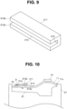
- Fig. 9 is a perspective view of the terminal holding unit 211 of the endoscope reprocessor 1 according to a modification 1 of the first embodiment of the present invention.
- Fig. 10 is an explanatory view for describing a disposition of the terminal holding unit 211 of the endoscope reprocessor 1 according to the modification 1 of the first embodiment of the present invention.
- this modification the description of components substantially identical to the corresponding components in other embodiments and modifications will be omitted.
- the description of components substantially identical to the corresponding components will be omitted also in other embodiments and modifications described hereinafter.
- the terminal holding unit 211 is made of a material, such as a resin, ceramic or metal. Assume the case where at least a portion of the terminal holding unit sandwiched between the observation terminal D and the top cover 11 is made of a material having visible light transmitting properties and a refractive index identical to a refractive index of the top cover 11. In such a case, it is possible to obtain an advantageous effect that a user can easily observe the display unit of the observation terminal D through the top cover 11.
- the terminal holding unit 211 is provided to the outer surface of the top cover 11 such that a direction from the other end toward the one end is aligned with a direction in which the observation terminal D is inserted.
- the terminal holding unit 211 includes holding plates 212a, 212b, an insertion opening 213, and an abutment plate 214.
- the holding plates 212a, 212b are provided substantially parallel to each other in a spaced apart manner by a distance that corresponds to the thickness of the observation terminal D.
- the lengths and the widths of the holding plates 212a, 212b are determined according to the size of the observation terminal D such that the holding plates 212a, 212b can stably hold the observation terminal D.
- the holding plate 212a is attached to a front surface of the cover panel 13.
- the insertion opening 213 is provided on the other end side of the holding plates 212a, 212b.
- the observation terminal D is inserted into the insertion opening 213 such that the camera D1 faces the treatment tank 31 with the cover panel 13 interposed between the camera D1 and the treatment tank 31.
- the abutment plate 214 is continuously formed between the holding plates 212a, 212b on one end side of the holding plates 212a, 212b.
- the observation terminal D inserted from the insertion opening 213 is caused to abut against the abutment plate 214.
- the observation terminal D is positioned such that the observation terminal D can pick up an image of the inside of the treatment tank 31.
- the terminal holding unit 211 has the insertion opening 213 on the other end side of the terminal holding unit 211, and include the abutment plate 214 on one end side of the terminal holding unit 211, the abutment plate 214 positioning the inserted observation terminal D.
- the holding plates 212a, 212b and the abutment plate 214 form a receiving base.
- a region surrounded by the holding plates 212a, 212b and the abutment plate 214 form a holding groove.
- the endoscope reprocessor 1 can hold the observation terminal D with the terminal holding unit 211 more easily.
- the holding plate 212b is fixed to the cover panel 13.
- a detachable unit 321 may be provided between the holding plate 212b and the cover panel 13.
- Fig. 11 is an upper perspective view of a terminal holding unit 311 of the endoscope reprocessor 1 according to a modification 2 of the first embodiment of the present invention.
- Fig. 12 is a lower perspective view of the terminal holding unit 311 of the endoscope reprocessor 1 according to the modification 2 of the first embodiment of the present invention.
- the detachable unit 321 is detachably attached to the cover panel 13.
- the detachable unit 321 includes a plate body 322, knobs 323, and suction cups 324.
- the plate body 322 is made of a material, such as a resin or metal.
- the plate body 322 is continuously formed with the cover panel 13 side of the holding plate 212a.
- the plate body 322 has a protruding portion 322a at each of both end portions of the plate body 322 in a length direction.
- the protruding portion 322a protrudes in the length direction from each of both end portions of the holding plate 212a.
- the knobs 323 are made of a material, such as a resin or metal, and are respectively provided to front surfaces of the protruding portions 322a. Each knob 323 is coupled with the center portion of the suction cup 324 by a screw member provided to penetrate the plate body 322. The knob 323 is turned in a forward direction or a reverse direction by the finger of a user gripping the outer peripheral portion of the knob 323, thus causing the screw member to advance or retract.
- the suction cups 324 are made of a material, such as a resin having elasticity, and are provided to back surfaces of the protruding portions 322a. Each suction cup 324 has a suction surface having a recessed curved shape on a back surface of the suction cup 324, and is detachably attached to the cover panel 13 by a negative pressure.
- the screw member pulls the center portion of the suction cup 324 in a direction toward the front surface, so that the suction cup 324 increases a suction force against the cover panel 13.
- the screw member pushes back the center portion of the suction cup 324 in a direction toward the back surface, so that the suction cup 324 reduces the suction force against the cover panel 13.
- a component to which the terminal holding unit 311 is attached is not limited to the top cover 11.
- the terminal holding unit 311 may be detachably attached to another component of the endoscope reprocessor 1.
- the terminal holding unit 311 includes the receiving base and the detachable unit 321.
- the receiving base holds the observation terminal D.
- the detachable unit 321 allows the receiving base to be detachably disposed.
- the terminal holding unit 311 can be detachably attached to the outer surface of the endoscope reprocessor 1 more easily.
- the observation terminal is held by the terminal holding unit such that the display unit of the observation terminal faces the top cover.
- the terminal holding unit 211, 311 has a substantially U shape in cross section continuing in the length direction.
- a terminal holding unit 411 may have a substantially L shape in cross section continuing in the length direction.
- the cover panel 13 or the reprocessor body 21 may play a role of the holding plate 212a in Fig. 9 .
- Fig. 13 is a side view of the terminal holding unit 411 of the endoscope reprocessor 1 according to a modification 3 of the first embodiment of the present invention.
- the terminal holding unit 411 is made of a material, such as a resin, ceramic or metal.
- the terminal holding unit 411 includes a holding plate 412, an insertion opening 413, and an abutment plate 414.
- the holding plate 412 is provided substantially parallel to the cover panel 13 in a spaced apart manner by a distance that corresponds to the thickness of the observation terminal D.
- the length and the width of the holding plate 412 are determined according to the size of the observation terminal D such that the holding plate 412 can stably hold the observation terminal D.
- the insertion opening 413 is provided on the other end side of the holding plate 412.
- the observation terminal D is inserted into the insertion opening 413 such that the camera D1 faces the treatment tank 31 with the cover panel 13 interposed between the camera D1 and the treatment tank 31.
- the abutment plate 414 is continuously formed between one end side of the holding plate 412 and the cover panel 13.
- the observation terminal D inserted from the insertion opening 413 is caused to abut against the abutment plate 414.
- the observation terminal D is positioned such that the observation terminal D can pick up an image of the inside of the treatment tank 31.
- the holding plate 412 and the abutment plate 414 form a receiving base.
- a region surrounded by the holding plate 412 and the abutment plate 414 form a holding groove.
- a detachable unit such as a suction cup, may be provided between the abutment plate 41 and the cover panel 13, for example.
- the terminal holding unit 411 has a substantially rectangular shape in cross section continuing in the length direction, and the terminal holding unit 411 and the cover panel 13 form a V shape in cross section.
- the holding plate 412 may also serve as the abutment plate 414.
- the terminal holding unit 411 includes no terminal connector 531.
- a terminal holding unit 511 may include the terminal connector 531 to which the observation terminal D is connected.
- Fig. 14 is a perspective view of the terminal holding unit 511 of the endoscope reprocessor 1 according to a modification 4 of the first embodiment of the present invention.
- the terminal holding unit 511 includes the terminal connector 531 and a battery 532.
- the terminal connector 531 is provided on a holding groove side of the abutment plate 414.
- the terminal connector 531 is configured such that the terminal connector 531 can be connected with the external connection connector D6 of the observation terminal D that is held.
- the battery 532 is connected with the terminal connector 531, and outputs power to the observation terminal D connected to the terminal connector 531.
- terminal connector 531 is connected with an external power source, and outputs power supplied from the external power source to the observation terminal D.
- the terminal holding unit 511 includes the insertion opening 413, the abutment plate 414, and the terminal connector 531.
- the observation terminal D is inserted into the insertion opening 413.
- the abutment plate 414 positions the inserted observation terminal D.
- the terminal connector 531 is provided to the abutment plate 414.
- the terminal connector 531 may be a connector for connecting the observation terminal D with an external memory or other smart device.
- the terminal holding unit 211 to 511 holds the observation terminal D substantially parallel to the cover panel 13.
- a terminal holding unit 611 may be configured such that the terminal holding unit 611 holds the observation terminal D at an angle at which the observation terminal D intersects with the cover panel 13 according to the purpose of use of the observation terminal D.
- Fig. 15 is an explanatory view for describing a disposition of the terminal holding unit 611 of the endoscope reprocessor 1 according to a modification 5 of the first embodiment of the present invention.
- the terminal holding unit 611 is made of a material, such as a resin or metal.
- the terminal holding unit 611 is provided to the front surface of the top cover 11 such that a direction from one end toward the other end is aligned with a direction in which the observation terminal D is inserted.
- the terminal holding unit 611 includes holding plates 612a, 612b, an insertion opening 613, and an abutment plate 614.
- One surface of the holding plate 612a is provided to the front surface of the cover panel 13.
- the other surface of the holding plate 612a inclines such that the other surface of the holding plate 612a approaches the top cover 11 as progresses from the one end side toward the other end side.
- the holding plate 612b is disposed substantially parallel to the holding plate 612a in a spaced apart manner by a distance that corresponds to the thickness of the observation terminal D.
- the insertion opening 613 is provided on the one end side of the holding plates 612a, 612b.
- the observation terminal D is inserted into the insertion opening 613 such that the camera D1, which acts as a receiving unit, faces the treatment tank 31 with the cover panel 13 interposed between the camera D1 and the treatment tank 31.
- the abutment plate 614 is continuously formed between the holding plates 612a, 612b on the other end side of the holding plates 612a, 612b.
- the observation terminal D inserted from the insertion opening 613 is caused to abut against the abutment plate 614.
- the holding plates 612a, 612b and the abutment plate 614 form a receiving base.
- a region surrounded by the holding plates 612a, 612b and the abutment plate 614 form a holding groove.
- the terminal holding unit 611 holds the observation terminal D in a state where the observation terminal D is inclined with respect to the treatment tank 31. Therefore, the observation terminal D can pick up a wider field of an image of the treatment tank 31.
- the observation terminal D may be disposed such that the observation terminal D is prevented from covering a portion of the treatment tank 31 close to one end side.
- the terminal holding unit 111 is provided to a portion away from the center of the top cover 11. In Fig. 2 , the terminal holding unit 111 is provided at a portion closer to the other end side than to the center portion, and holds the observation terminal D inserted in a direction from the other end side toward one end side.
- a user is allowed to visually check a portion (a dashed-and-double-dotted line in Fig. 2 ) disposed closer to the one end side than to the center portion of the treatment tank 31.
- the user is allowed to visually check ejection of liquid from the ejection ports T3 and whether or not liquid is being appropriately discharged from the water supply circulation nozzle 37.
- a terminal holding unit 711 may be configured such that the terminal holding unit 711 can cause the observation terminal D to be rotated with respect to the cover panel 13.
- Fig. 16 is a top plan view for describing a first position of the terminal holding unit 711 of the endoscope reprocessor 1 according to a second embodiment of the present invention.
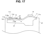
- Fig. 17 is an explanatory view for describing the first position of the terminal holding unit 711 of the endoscope reprocessor 1 according to the second embodiment of the present invention.
- Fig. 18 is a perspective view for describing a second position of the terminal holding unit 711 of the endoscope reprocessor 1 according to the second embodiment of the present invention.
- Fig. 19 is an explanatory view for describing the second position of the terminal holding unit 711 of the endoscope reprocessor 1 according to the second embodiment of the present invention.
- the terminal holding unit 711 is made of a material, such as a resin or metal.
- the terminal holding unit 711 is provided to the front surface of the top cover 11 such that a direction from one end toward the other end is aligned with a direction in which the observation terminal D is inserted.
- the terminal holding unit 711 includes holding plates 712a, 712b, an insertion opening 713, an abutment plate 714, and a rotating unit 741.
- the holding plates 712a, 712b are provided substantially parallel to each other in a spaced-apart manner by a distance that corresponds to the thickness of the observation terminal D.
- the insertion opening 713 is provided on a side of the holding plates 712a, 712b opposite to the rotating unit 741.
- the observation terminal D is inserted into the insertion opening 713.
- the abutment plate 714 is continuously formed between the holding plates 712a, 712b on a rotating unit 741 side of the holding plates 712a, 712b.
- the observation terminal D is inserted from the insertion opening 713 such that the camera D2 is directed toward the holding plate 712a side, and the camera D1 is directed toward the holding plate 712b side, and the observation terminal D is caused to abut against the observation terminal D.
- the holding plates 712a, 712b and the abutment plate 714 form a receiving base.
- a region surrounded by the holding plates 712a, 712b and the abutment plate 714 form a holding groove.
- the rotating unit 741 is provided to the front surface of the top cover 11.
- the rotating unit 741 has a rotation axis extending in a direction orthogonal to a direction in which the observation terminal D is inserted.
- the rotating unit 741 supports the abutment plate 714 such that the abutment plate 714 can rotate about the rotation axis.
- the terminal holding unit 711 is disposed at either one of the first position or the second position.
- the first position is a position where the insertion opening 713 is directed to the one end side of the top cover 11.
- the camera D2 is disposed to face the treatment tank 31.
- the terminal holding unit 711 is brought into the first position.
- the second position is a position where the insertion opening 713 is directed to the other end side of the top cover 11.
- the camera D1 is disposed to protrude from the other end side of the top cover 11.
- the terminal holding unit 711 is brought into the second position.
- the terminal holding unit 711 includes the receiving base and the rotating unit 741.
- the receiving base holds the observation terminal D.
- the rotating unit 741 rotatably supports the receiving base.
- the rotating unit 741 causes the receiving base to be rotated such that the receiving base is in the first position with the top cover 11 being in the closed state, and the receiving base is in the second position different from the first position with the top cover 11 being in the open state.
- various types of information such as a manual, an instruction, a notification, or warning, is displayed on the display unit D5 in a state where the top cover 11 is brought into the open state, thus causing the terminal holding unit 711 to be brought into the second position.
- a user can perform a work for reprocessing, such as disposing or connecting the endoscope E in the treatment tank 31 by referencing the various types of information displayed on the display unit D5.
- the endoscope reprocessor 1 includes the terminal holding unit 711 capable of being rotated by the rotating unit 741, and can be more easily equipped with the observation terminal D, which determines whether or not the endoscope reprocessor 1 is being used in an appropriate use state.
- the endoscope reprocessor 1 has no light reflecting structure.
- the endoscope reprocessor 1 may have the light reflecting structure.
- Fig. 20 is a perspective view of the endoscope reprocessor 1 according to a third embodiment not part of of the present invention.
- the reprocessor body 21 includes a terminal holding unit 811, an observation panel 813, which acts as a transmitting unit, a mirror 851 that forms the light reflecting structure, and an observation terminal F.
- the terminal holding unit 811 is made of a material, such as a resin or metal.
- the terminal holding unit 811 is disposed adjacent to the transmitting unit at an outer peripheral side portion of the reprocessor body 21.
- the terminal holding unit 811 includes a holding base that holds the observation terminal F.
- the observation panel 813 is made of a material, such as a resin, and has light transmitting properties.
- the observation panel 813 is provided to the outer peripheral side portion of the reprocessor body 21 to allow an observation of the inside of the treatment tank 31.
- the mirror 851 is made of a material, such as glass or metal.
- the mirror 851 is provided to the wall portion of the treatment tank 31 at a position that faces the observation panel 813.
- the observation terminal F is held by the terminal holding unit 811.
- the observation terminal F includes a camera F1, a control unit F3, and a communication unit F4.
- the camera F1 is disposed such that the camera F1 faces the mirror 851 with the observation panel 813 interposed between the camera F1 and the mirror 851.
- the camera F1 can pick up an image of the inside of the treatment tank 31 displayed on the mirror 851.
- the configurations of the control unit F3 and of the communication unit F4 are substantially same as the configurations of the control unit D3 and the communication unit D4 and hence, the repeated description will be omitted.
- the endoscope reprocessor 1 allows the observation terminal F to observe also the back side of an article accommodated in the treatment tank 31 with the mirror 851, and can be more easily equipped with the observation terminal F, which determines whether or not the endoscope reprocessor 1 is being used in an appropriate use state.
- an observation wave is light.
- the observation wave may be an electromagnetic wave including visible light, invisible light, and the like.
- the observation wave is not limited to an electromagnetic wave, but may be an acoustic wave.
- the observation terminal D, F may include a filter that receives only a specific wavelength of the observation wave.
- the observation terminal D, F is a portable information terminal of a tablet type or a camera terminal.
- the observation terminal D, F is not limited to the above.
- the observation terminal D may be a portable information terminal, such as a smartphone, or a camera terminal, such as a Web camera.
- one set of the observation terminal D, F and the terminal holding unit 111 to 811 is provided.
- the configuration is not limited to such a configuration.
- a plural sets of the observation terminal D, F and the terminal holding unit 111 to 811 may be provided.
- the terminal holding unit 111 to 811 is configured such that the terminal holding unit 111 to 811 can hold a portable information terminal of a tablet type or a camera terminal.
- the shape of the terminal holding unit 111 to 811 is not limited to the shape described in the examples in the embodiments and the modifications.
- a holding base including the terminal holding unit is separate from an endoscope reprocessor.
- the holding base may be able to hold the observation terminal D such that the observation terminal D can observe the treatment tank 31 with the cover panel 13 being in the closed state or in the open state.
- An example of the shape of the holding base may be a shape of a music stand.
- Another example of the shape of the holding base may be a shape formed of a hanging portion from which the observation terminal D is hung and a support portion that supports the hanging portion.
- the endoscope reprocessor 1, the observation terminal D, or the holding base may include at least one of a detection unit and an informing unit.
- the detection unit is configured to detect whether or not the treatment tank 31 is within a visual field range of the observation terminal D.
- the informing unit is configured to inform the detection result from the detection unit.
- the endoscope reprocessor 1, the observation terminal D, or the holding base may include at least one of a calculation unit and an informing unit.
- the calculation unit is configured to calculate a position of the holding base, a height of the holding portion, or an angle of the terminal holding unit to allow the treatment tank 31 to be within the visual field range of the observation terminal D.
- the informing unit is configured to inform the calculation result from the calculation unit.
- the observation terminal D, F performs determination processing on the detection result.
- a device that performs the determination processing is not limited to the observation terminal D, F.
- the device that performs the determination processing may be any of a PC terminal, an information terminal such as a server, a portable information terminal such as a smartphone, a wearable device of a type such as a watch type, a pendant type, a brooch type, a glasses type, or a headband hat type, or the reprocessor body 21 instead of the observation terminal D, F.
- a notification processing is performed by the reprocessor body 21.
- the notification processing may be performed by any one of a PC terminal, an information terminal such as a server, a portable information terminal such as a smartphone or a tablet, a wearable device of a type such as a watch type, a pendant type, a brooch type, a glasses type, or a headband hat type, a projector, or a virtual image monitor instead of the reprocessor body 21.
Landscapes
- Health & Medical Sciences (AREA)
- Life Sciences & Earth Sciences (AREA)
- Surgery (AREA)
- Engineering & Computer Science (AREA)
- Biomedical Technology (AREA)
- Molecular Biology (AREA)
- Pathology (AREA)
- Radiology & Medical Imaging (AREA)
- Nuclear Medicine, Radiotherapy & Molecular Imaging (AREA)
- Biophysics (AREA)
- Physics & Mathematics (AREA)
- Heart & Thoracic Surgery (AREA)
- Medical Informatics (AREA)
- Optics & Photonics (AREA)
- Animal Behavior & Ethology (AREA)
- General Health & Medical Sciences (AREA)
- Public Health (AREA)
- Veterinary Medicine (AREA)
- Signal Processing (AREA)
- Instruments For Viewing The Inside Of Hollow Bodies (AREA)
- Endoscopes (AREA)
Claims (12)
- Un dispositif (1) de retraitement d'endoscope, comprenant:un réservoir de traitement (31);un couvercle supérieur (11) comportant une unité de transmission (13) constituée d'un matériau de transmission qui permet à la lumière visible de passer à travers le matériau de transmission, l'unité de transmission (13) étant disposée de telle sorte que la lumière visible puisse passer d'une surface extérieure du dispositif de retraitement jusqu'à l'intérieur d'un réservoir de traitement (31);un terminal d'observation (D) comprenant une unité de réception (D1) qui reçoit la lumière visible et une unité d'affichage (D5); etau moins une unité (111) de maintien de terminal disposée sur une surface extérieure du couvercle supérieur (11), et configurée pour maintenir le terminal d'observation (D) dans une position qui permet au terminal d'observation (D) d'observer l'intérieur du réservoir de traitement (31) à travers l'unité de transmission (13), le terminal d'observation (D) étant maintenu par l'unité (111) de maintien de terminal de telle sorte que l'unité d'affichage (D5) soit face au couvercle supérieur (11) et qu'un utilisateur puisse observer l'unité d'affichage (D5) du terminal d'observation (D) au travers du couvercle supérieur (11).
- Le dispositif (1) de retraitement d'endoscope selon la revendication 1, dans lequel
l'unité de transmission (13) est formée du couvercle supérieur (11) qui recouvre le réservoir de traitement (31). - Le dispositif (1) de retraitement d'endoscope selon la revendication 2, dans lequelune extrémité du couvercle supérieur (11) est reliée à un corps de dispositif de retraitement par une charnière, et une autre extrémité du couvercle supérieur (11) tourne autour de l'une des extrémités du couvercle supérieur (11), etl'unité (111) de maintien de terminal est prévue de telle sorte qu'une direction allant de l'autre extrémité vers l'une des extrémités soit alignée avec une direction dans laquelle le terminal d'observation (D) est inséré, l'unité (111) de maintien de terminal ayant une ouverture d'insertion sur un côté de l'autre extrémité, et comprenant une plaque de butée sur un côté de ladite une extrémité, la plaque de butée positionnant le terminal d'observation (D) insérée.
- Le dispositif (1) de retraitement d'endoscope selon la revendication 1, dans lequell'unité de transmission (13) est prévue sur une partie latérale périphérique extérieure d'un corps de dispositif de retraitement de façon à permettre une observation de l'intérieur du réservoir de traitement (31), etl'unité (111) de maintien de terminal est disposée de façon adjacente à l'unité de transmission (13) au niveau de la partie latérale périphérique extérieure.
- Le dispositif (1) de retraitement d'endoscope selon la revendication 1, dans lequell'unité (111) de maintien de terminal comprendune base de réception qui maintient le terminal d'observation (D), etune unité détachable qui permet à la base de réception d'être disposée de manière détachable.
- Le dispositif (1) de retraitement d'endoscope selon la revendication 2, dans lequell'unité (111) de maintien de terminal comprendune base de réception qui maintient le terminal d'observation (D), etune unité rotative qui supporte de manière rotative la base de réception, etl'unité rotative provoque la rotation de la base de réception de telle sorte quela base de réception soit dans une première position avec le couvercle supérieur (11) dans un état fermé, etla base de réception soit dans une deuxième position différente de la première position avec le couvercle supérieur (11) dans un état ouvert.
- Le dispositif (1) de retraitement d'endoscope selon la revendication 1, dans lequell'unité (111) de maintien de terminal comprendune ouverture d'insertion qui permet une insertion du terminal d'observation (D),une plaque de butée qui positionne le terminal d'observation (D) inséré, etun connecteur de terminal fourni à la plaque de butée.
- Le dispositif (1) de retraitement d'endoscope selon la revendication 1, dans lequel l'unité (111) de maintien de terminal maintient le terminal d'observation (D) dans un état dans lequel le terminal d'observation (D) est incliné par rapport au réservoir de traitement (31).
- Le dispositif (1) de retraitement d'endoscope selon la revendication 2, dans lequel l'unité (111) de maintien de terminal est disposée en une position éloignée d'un centre du couvercle supérieur (11), et maintient le terminal d'observation (D) inséré dans une direction depuis un autre côté d'extrémité vers un côté d'extrémité.
- Le dispositif (1) de retraitement d'endoscope selon la revendication 2, dans lequel
l'unité (111) de maintien de terminal maintient le terminal d'observation (D) de façon à permettre à une surface entière de l'unité d'affichage (D5) du terminal d'observation (D) d'être vue à travers une surface intérieure du couvercle supérieur (11) dans un état dans lequel le terminal d'observation (D) est maintenu par l'unité (111) de maintien de terminal de telle sorte que l'unité d'affichage (D5) soit face au couvercle supérieur (11). - Le dispositif (1) de retraitement d'endoscope selon la revendication 10, dans lequel
l'unité (111) de maintien de terminal comprend une première partie de maintien et une deuxième partie de maintien formée d'une partie du couvercle supérieur (11), et la première partie de maintien et la deuxième partie de maintien prennent en sandwich le terminal d'observation (D) pour positionner le terminal d'observation (D) sur le couvercle supérieur (11). - Le dispositif (1) de retraitement d'endoscope selon la revendication 2, dans lequelle couvercle supérieur (11) a une propriété de transmission de lumière visible,l'unité (111) de maintien de terminal maintient le terminal d'observation (D) en serrant le terminal d'observation (D), etau moins une partie de l'unité (111) de maintien de terminal prise en sandwich entre le terminal d'observation (D) et le couvercle supérieur (11) est constituée d'un matériau ayant une propriété de transmission de lumière visible et un indice de réfraction identique à un indice de réfraction du couvercle supérieur (11).
Applications Claiming Priority (2)
| Application Number | Priority Date | Filing Date | Title |
|---|---|---|---|
| JP2018079080 | 2018-04-17 | ||
| PCT/JP2019/014968 WO2019203010A1 (fr) | 2018-04-17 | 2019-04-04 | Reprocesseur d'endoscope |
Publications (3)
| Publication Number | Publication Date |
|---|---|
| EP3782533A1 EP3782533A1 (fr) | 2021-02-24 |
| EP3782533A4 EP3782533A4 (fr) | 2021-12-29 |
| EP3782533B1 true EP3782533B1 (fr) | 2024-12-11 |
Family
ID=68239683
Family Applications (1)
| Application Number | Title | Priority Date | Filing Date |
|---|---|---|---|
| EP19789459.5A Active EP3782533B1 (fr) | 2018-04-17 | 2019-04-04 | Reprocesseur d'endoscope |
Country Status (5)
| Country | Link |
|---|---|
| US (1) | US12102299B2 (fr) |
| EP (1) | EP3782533B1 (fr) |
| JP (1) | JP6929448B2 (fr) |
| CN (1) | CN112312824B (fr) |
| WO (1) | WO2019203010A1 (fr) |
Families Citing this family (6)
| Publication number | Priority date | Publication date | Assignee | Title |
|---|---|---|---|---|
| WO2020190459A1 (fr) | 2019-03-19 | 2020-09-24 | Medivators Inc. | Couvercles de plateaux pour endoscope aérés, systèmes et procédés |
| EP4497409A3 (fr) * | 2019-06-20 | 2025-06-25 | Medivators Inc. | Plateau de stockage d'endoscope ayant des ouvertures et procédé d'utilisation |
| EP3986230B1 (fr) | 2019-06-20 | 2025-08-13 | Medivators Inc. | Système de stockage d'endoscopes |
| US11974721B2 (en) | 2019-06-20 | 2024-05-07 | Medivators Inc. | Endoscope storage cart, system and methods |
| JP7423739B2 (ja) | 2020-02-18 | 2024-01-29 | オリンパス株式会社 | 制御装置、内視鏡の配置状態判定方法、及び、プログラム |
| AU2021225770B2 (en) | 2020-02-25 | 2025-02-27 | Medivators Inc. | Stackable endoscope storage tray and method of use |
Family Cites Families (18)
| Publication number | Priority date | Publication date | Assignee | Title |
|---|---|---|---|---|
| JPH10296194A (ja) * | 1997-04-25 | 1998-11-10 | Mitsubishi Kakoki Kaisha Ltd | ノズル噴射式洗浄装置及びノズル噴射式洗浄方法 |
| JP3691764B2 (ja) * | 2001-03-07 | 2005-09-07 | オリンパス株式会社 | オートクレーブ装置 |
| JP2002272684A (ja) | 2001-03-16 | 2002-09-24 | Olympus Optical Co Ltd | 内視鏡洗滌装置と洗滌情報付き内視鏡 |
| JP4103135B2 (ja) * | 2003-04-18 | 2008-06-18 | ソニー株式会社 | 冷蔵庫 |
| CN1727942A (zh) * | 2004-07-31 | 2006-02-01 | 西门子(中国)有限公司 | 双显示屏的电子装置 |
| CN201006048Y (zh) * | 2005-11-11 | 2008-01-16 | 奥林巴斯医疗株式会社 | 内窥镜洗涤消毒装置 |
| JP2009039207A (ja) * | 2007-08-07 | 2009-02-26 | Fujifilm Corp | 内視鏡の漏水検知装置 |
| JP5231027B2 (ja) * | 2008-01-10 | 2013-07-10 | オリンパスメディカルシステムズ株式会社 | 内視鏡洗浄消毒装置 |
| US8414471B2 (en) * | 2008-10-28 | 2013-04-09 | Mobile Aspects, Inc. | Endoscope storage cabinet, tracking system, and signal emitting member |
| DE102011078765A1 (de) * | 2011-07-06 | 2013-01-10 | BSH Bosch und Siemens Hausgeräte GmbH | Geschirrspülmaschine mit zumindest einem lichtdurchlässigen Teilbereich auf ihrer Türinnenwandung |
| EP2638847B1 (fr) | 2011-07-15 | 2014-10-15 | Olympus Medical Systems Corp. | Machine à nettoyage/desinfection d'endoscope |
| DE102013202540A1 (de) * | 2013-02-18 | 2014-08-21 | Olympus Winter & Ibe Gmbh | Verfahren zum Betrieb einer Aufbereitungsvorrichtung und Aufbereitungsvorrichtung für chirurgische Instrumente |
| JP5566494B2 (ja) * | 2013-03-27 | 2014-08-06 | オリンパスメディカルシステムズ株式会社 | 内視鏡洗浄消毒装置 |
| WO2016194448A1 (fr) * | 2015-06-05 | 2016-12-08 | オリンパス株式会社 | Procédé permettant de commander un dispositif de retraitement d'endoscope |
| WO2017038132A1 (fr) * | 2015-09-02 | 2017-03-09 | オリンパス株式会社 | Retraiteur d'endoscope |
| JP6230765B1 (ja) * | 2016-04-25 | 2017-11-15 | オリンパス株式会社 | 内視鏡再生処理具 |
| CN206080475U (zh) * | 2016-07-02 | 2017-04-12 | 刘燕 | 便携式宫颈诊疗仪 |
| JP6763753B2 (ja) | 2016-11-16 | 2020-09-30 | マクセルホールディングス株式会社 | 美容器具 |
-
2019
- 2019-04-04 JP JP2020514074A patent/JP6929448B2/ja active Active
- 2019-04-04 EP EP19789459.5A patent/EP3782533B1/fr active Active
- 2019-04-04 CN CN201980040396.3A patent/CN112312824B/zh active Active
- 2019-04-04 WO PCT/JP2019/014968 patent/WO2019203010A1/fr not_active Ceased
-
2020
- 2020-09-30 US US17/038,743 patent/US12102299B2/en active Active
Also Published As
| Publication number | Publication date |
|---|---|
| EP3782533A4 (fr) | 2021-12-29 |
| CN112312824B (zh) | 2025-01-10 |
| CN112312824A (zh) | 2021-02-02 |
| WO2019203010A1 (fr) | 2019-10-24 |
| JPWO2019203010A1 (ja) | 2021-03-11 |
| US12102299B2 (en) | 2024-10-01 |
| JP6929448B2 (ja) | 2021-09-01 |
| US20210076923A1 (en) | 2021-03-18 |
| EP3782533A1 (fr) | 2021-02-24 |
Similar Documents
| Publication | Publication Date | Title |
|---|---|---|
| EP3782533B1 (fr) | Reprocesseur d'endoscope | |
| US4971034A (en) | Body cavity pressure adjusting device for endoscope and laser medical treatment apparatus including body cavity pressure adjusting device | |
| US12354297B2 (en) | Control apparatus, endoscope positioning state determination method, and non-transitory recording medium | |
| JP5249480B1 (ja) | 内視鏡洗浄消毒装置 | |
| EP1779763A1 (fr) | Endoscope et couvercle d'extremite | |
| JP2004033487A (ja) | 内視鏡装置 | |
| CN100438816C (zh) | 灭菌用收纳箱和内窥镜系统 | |
| CN109922705A (zh) | 内窥镜、内窥镜的线材安装方法以及内窥镜的线材拆卸方法 | |
| JP2001198086A (ja) | 医療機器用コネクター装置 | |
| CN106164639A (zh) | 内窥镜漏水自动检测装置及其检测方法 | |
| JP4772450B2 (ja) | 内視鏡 | |
| US5487376A (en) | Washing apparatus for a protection cover for an endoscope | |
| JP7386966B2 (ja) | 内視鏡汚れ検知装置、制御装置及び内視鏡汚れ検知方法 | |
| US20140012079A1 (en) | Pipe endoscope | |
| CN100441137C (zh) | 内窥镜系统以及过滤单元 | |
| CN115778570A (zh) | 一种内窥镜检测方法、控制装置及检测系统 | |
| JP5058759B2 (ja) | 内視鏡搬送ケース | |
| JP3590107B2 (ja) | 内視鏡検査装置 | |
| JP2018143719A (ja) | 内視鏡システムおよび内視鏡の漏水検知処理方法 | |
| CN215534246U (zh) | 一种腹腔镜 | |
| KR20160056704A (ko) | 내시경용 헤드캡 | |
| CN206275897U (zh) | 用于胃管的图像采集置入装置以及胃管系统 | |
| KR102881763B1 (ko) | 치근관구 탐색이 용이한 초소형 카메라 시스템 | |
| JPH07184840A (ja) | 内視鏡カバー気密検査装置 | |
| KR20170139840A (ko) | 내시경의 일회용 프로브 및 그 내시경의 제어 방법 |
Legal Events
| Date | Code | Title | Description |
|---|---|---|---|
| STAA | Information on the status of an ep patent application or granted ep patent |
Free format text: STATUS: THE INTERNATIONAL PUBLICATION HAS BEEN MADE |
|
| PUAI | Public reference made under article 153(3) epc to a published international application that has entered the european phase |
Free format text: ORIGINAL CODE: 0009012 |
|
| STAA | Information on the status of an ep patent application or granted ep patent |
Free format text: STATUS: REQUEST FOR EXAMINATION WAS MADE |
|
| 17P | Request for examination filed |
Effective date: 20201116 |
|
| AK | Designated contracting states |
Kind code of ref document: A1 Designated state(s): AL AT BE BG CH CY CZ DE DK EE ES FI FR GB GR HR HU IE IS IT LI LT LU LV MC MK MT NL NO PL PT RO RS SE SI SK SM TR |
|
| AX | Request for extension of the european patent |
Extension state: BA ME |
|
| DAV | Request for validation of the european patent (deleted) | ||
| DAX | Request for extension of the european patent (deleted) | ||
| A4 | Supplementary search report drawn up and despatched |
Effective date: 20211201 |
|
| RIC1 | Information provided on ipc code assigned before grant |
Ipc: A61B 1/12 20060101AFI20211125BHEP |
|
| P01 | Opt-out of the competence of the unified patent court (upc) registered |
Effective date: 20230517 |
|
| GRAP | Despatch of communication of intention to grant a patent |
Free format text: ORIGINAL CODE: EPIDOSNIGR1 |
|
| STAA | Information on the status of an ep patent application or granted ep patent |
Free format text: STATUS: GRANT OF PATENT IS INTENDED |
|
| INTG | Intention to grant announced |
Effective date: 20240730 |
|
| GRAS | Grant fee paid |
Free format text: ORIGINAL CODE: EPIDOSNIGR3 |
|
| GRAA | (expected) grant |
Free format text: ORIGINAL CODE: 0009210 |
|
| STAA | Information on the status of an ep patent application or granted ep patent |
Free format text: STATUS: THE PATENT HAS BEEN GRANTED |
|
| AK | Designated contracting states |
Kind code of ref document: B1 Designated state(s): AL AT BE BG CH CY CZ DE DK EE ES FI FR GB GR HR HU IE IS IT LI LT LU LV MC MK MT NL NO PL PT RO RS SE SI SK SM TR |
|
| REG | Reference to a national code |
Ref country code: GB Ref legal event code: FG4D |
|
| REG | Reference to a national code |
Ref country code: CH Ref legal event code: EP |
|
| REG | Reference to a national code |
Ref country code: IE Ref legal event code: FG4D |
|
| REG | Reference to a national code |
Ref country code: DE Ref legal event code: R096 Ref document number: 602019063422 Country of ref document: DE |
|
| REG | Reference to a national code |
Ref country code: LT Ref legal event code: MG9D |
|
| PG25 | Lapsed in a contracting state [announced via postgrant information from national office to epo] |
Ref country code: HR Free format text: LAPSE BECAUSE OF FAILURE TO SUBMIT A TRANSLATION OF THE DESCRIPTION OR TO PAY THE FEE WITHIN THE PRESCRIBED TIME-LIMIT Effective date: 20241211 |
|
| PG25 | Lapsed in a contracting state [announced via postgrant information from national office to epo] |
Ref country code: FI Free format text: LAPSE BECAUSE OF FAILURE TO SUBMIT A TRANSLATION OF THE DESCRIPTION OR TO PAY THE FEE WITHIN THE PRESCRIBED TIME-LIMIT Effective date: 20241211 |
|
| PG25 | Lapsed in a contracting state [announced via postgrant information from national office to epo] |
Ref country code: BG Free format text: LAPSE BECAUSE OF FAILURE TO SUBMIT A TRANSLATION OF THE DESCRIPTION OR TO PAY THE FEE WITHIN THE PRESCRIBED TIME-LIMIT Effective date: 20241211 |
|
| REG | Reference to a national code |
Ref country code: NL Ref legal event code: MP Effective date: 20241211 |
|
| PG25 | Lapsed in a contracting state [announced via postgrant information from national office to epo] |
Ref country code: ES Free format text: LAPSE BECAUSE OF FAILURE TO SUBMIT A TRANSLATION OF THE DESCRIPTION OR TO PAY THE FEE WITHIN THE PRESCRIBED TIME-LIMIT Effective date: 20241211 |
|
| PG25 | Lapsed in a contracting state [announced via postgrant information from national office to epo] |
Ref country code: NO Free format text: LAPSE BECAUSE OF FAILURE TO SUBMIT A TRANSLATION OF THE DESCRIPTION OR TO PAY THE FEE WITHIN THE PRESCRIBED TIME-LIMIT Effective date: 20250311 |
|
| PG25 | Lapsed in a contracting state [announced via postgrant information from national office to epo] |
Ref country code: GR Free format text: LAPSE BECAUSE OF FAILURE TO SUBMIT A TRANSLATION OF THE DESCRIPTION OR TO PAY THE FEE WITHIN THE PRESCRIBED TIME-LIMIT Effective date: 20250312 Ref country code: LV Free format text: LAPSE BECAUSE OF FAILURE TO SUBMIT A TRANSLATION OF THE DESCRIPTION OR TO PAY THE FEE WITHIN THE PRESCRIBED TIME-LIMIT Effective date: 20241211 |
|
| PG25 | Lapsed in a contracting state [announced via postgrant information from national office to epo] |
Ref country code: RS Free format text: LAPSE BECAUSE OF FAILURE TO SUBMIT A TRANSLATION OF THE DESCRIPTION OR TO PAY THE FEE WITHIN THE PRESCRIBED TIME-LIMIT Effective date: 20250311 |
|
| PG25 | Lapsed in a contracting state [announced via postgrant information from national office to epo] |
Ref country code: NL Free format text: LAPSE BECAUSE OF FAILURE TO SUBMIT A TRANSLATION OF THE DESCRIPTION OR TO PAY THE FEE WITHIN THE PRESCRIBED TIME-LIMIT Effective date: 20241211 |
|
| REG | Reference to a national code |
Ref country code: AT Ref legal event code: MK05 Ref document number: 1749682 Country of ref document: AT Kind code of ref document: T Effective date: 20241211 |
|
| PG25 | Lapsed in a contracting state [announced via postgrant information from national office to epo] |
Ref country code: SM Free format text: LAPSE BECAUSE OF FAILURE TO SUBMIT A TRANSLATION OF THE DESCRIPTION OR TO PAY THE FEE WITHIN THE PRESCRIBED TIME-LIMIT Effective date: 20241211 |
|
| PG25 | Lapsed in a contracting state [announced via postgrant information from national office to epo] |
Ref country code: PL Free format text: LAPSE BECAUSE OF FAILURE TO SUBMIT A TRANSLATION OF THE DESCRIPTION OR TO PAY THE FEE WITHIN THE PRESCRIBED TIME-LIMIT Effective date: 20241211 |
|
| PGFP | Annual fee paid to national office [announced via postgrant information from national office to epo] |
Ref country code: DE Payment date: 20250417 Year of fee payment: 7 |
|
| PG25 | Lapsed in a contracting state [announced via postgrant information from national office to epo] |
Ref country code: IS Free format text: LAPSE BECAUSE OF FAILURE TO SUBMIT A TRANSLATION OF THE DESCRIPTION OR TO PAY THE FEE WITHIN THE PRESCRIBED TIME-LIMIT Effective date: 20250411 |
|
| PG25 | Lapsed in a contracting state [announced via postgrant information from national office to epo] |
Ref country code: PT Free format text: LAPSE BECAUSE OF FAILURE TO SUBMIT A TRANSLATION OF THE DESCRIPTION OR TO PAY THE FEE WITHIN THE PRESCRIBED TIME-LIMIT Effective date: 20250411 |
|
| PG25 | Lapsed in a contracting state [announced via postgrant information from national office to epo] |
Ref country code: EE Free format text: LAPSE BECAUSE OF FAILURE TO SUBMIT A TRANSLATION OF THE DESCRIPTION OR TO PAY THE FEE WITHIN THE PRESCRIBED TIME-LIMIT Effective date: 20241211 |
|
| PG25 | Lapsed in a contracting state [announced via postgrant information from national office to epo] |
Ref country code: RO Free format text: LAPSE BECAUSE OF FAILURE TO SUBMIT A TRANSLATION OF THE DESCRIPTION OR TO PAY THE FEE WITHIN THE PRESCRIBED TIME-LIMIT Effective date: 20241211 Ref country code: AT Free format text: LAPSE BECAUSE OF FAILURE TO SUBMIT A TRANSLATION OF THE DESCRIPTION OR TO PAY THE FEE WITHIN THE PRESCRIBED TIME-LIMIT Effective date: 20241211 |
|
| PG25 | Lapsed in a contracting state [announced via postgrant information from national office to epo] |
Ref country code: SK Free format text: LAPSE BECAUSE OF FAILURE TO SUBMIT A TRANSLATION OF THE DESCRIPTION OR TO PAY THE FEE WITHIN THE PRESCRIBED TIME-LIMIT Effective date: 20241211 |
|
| PG25 | Lapsed in a contracting state [announced via postgrant information from national office to epo] |
Ref country code: CZ Free format text: LAPSE BECAUSE OF FAILURE TO SUBMIT A TRANSLATION OF THE DESCRIPTION OR TO PAY THE FEE WITHIN THE PRESCRIBED TIME-LIMIT Effective date: 20241211 |
|
| PG25 | Lapsed in a contracting state [announced via postgrant information from national office to epo] |
Ref country code: IT Free format text: LAPSE BECAUSE OF FAILURE TO SUBMIT A TRANSLATION OF THE DESCRIPTION OR TO PAY THE FEE WITHIN THE PRESCRIBED TIME-LIMIT Effective date: 20241211 |
|
| PG25 | Lapsed in a contracting state [announced via postgrant information from national office to epo] |
Ref country code: SE Free format text: LAPSE BECAUSE OF FAILURE TO SUBMIT A TRANSLATION OF THE DESCRIPTION OR TO PAY THE FEE WITHIN THE PRESCRIBED TIME-LIMIT Effective date: 20241211 |
|
| REG | Reference to a national code |
Ref country code: DE Ref legal event code: R097 Ref document number: 602019063422 Country of ref document: DE |
|
| PG25 | Lapsed in a contracting state [announced via postgrant information from national office to epo] |
Ref country code: DK Free format text: LAPSE BECAUSE OF FAILURE TO SUBMIT A TRANSLATION OF THE DESCRIPTION OR TO PAY THE FEE WITHIN THE PRESCRIBED TIME-LIMIT Effective date: 20241211 |
|
| PLBE | No opposition filed within time limit |
Free format text: ORIGINAL CODE: 0009261 |
|
| STAA | Information on the status of an ep patent application or granted ep patent |
Free format text: STATUS: NO OPPOSITION FILED WITHIN TIME LIMIT |
|
| REG | Reference to a national code |
Ref country code: CH Ref legal event code: L10 Free format text: ST27 STATUS EVENT CODE: U-0-0-L10-L00 (AS PROVIDED BY THE NATIONAL OFFICE) Effective date: 20251022 |
|
| 26N | No opposition filed |
Effective date: 20250912 |
|
| REG | Reference to a national code |
Ref country code: CH Ref legal event code: H13 Free format text: ST27 STATUS EVENT CODE: U-0-0-H10-H13 (AS PROVIDED BY THE NATIONAL OFFICE) Effective date: 20251125 |
|
| PG25 | Lapsed in a contracting state [announced via postgrant information from national office to epo] |
Ref country code: LU Free format text: LAPSE BECAUSE OF NON-PAYMENT OF DUE FEES Effective date: 20250404 |
|
| PG25 | Lapsed in a contracting state [announced via postgrant information from national office to epo] |
Ref country code: MC Free format text: LAPSE BECAUSE OF FAILURE TO SUBMIT A TRANSLATION OF THE DESCRIPTION OR TO PAY THE FEE WITHIN THE PRESCRIBED TIME-LIMIT Effective date: 20241211 |
|
| GBPC | Gb: european patent ceased through non-payment of renewal fee |
Effective date: 20250404 |
|
| REG | Reference to a national code |
Ref country code: BE Ref legal event code: MM Effective date: 20250430 |
|
| PG25 | Lapsed in a contracting state [announced via postgrant information from national office to epo] |
Ref country code: GB Free format text: LAPSE BECAUSE OF NON-PAYMENT OF DUE FEES Effective date: 20250404 |
|
| PG25 | Lapsed in a contracting state [announced via postgrant information from national office to epo] |
Ref country code: FR Free format text: LAPSE BECAUSE OF NON-PAYMENT OF DUE FEES Effective date: 20250430 |
|
| PG25 | Lapsed in a contracting state [announced via postgrant information from national office to epo] |
Ref country code: BE Free format text: LAPSE BECAUSE OF NON-PAYMENT OF DUE FEES Effective date: 20250430 |
|
| PG25 | Lapsed in a contracting state [announced via postgrant information from national office to epo] |
Ref country code: CH Free format text: LAPSE BECAUSE OF NON-PAYMENT OF DUE FEES Effective date: 20250430 |
|
| PG25 | Lapsed in a contracting state [announced via postgrant information from national office to epo] |
Ref country code: IE Free format text: LAPSE BECAUSE OF NON-PAYMENT OF DUE FEES Effective date: 20250404 |