EP3782848B1 - Ladekupplung mit griff und elektronische fahrzeugladevorrichtung damit - Google Patents
Ladekupplung mit griff und elektronische fahrzeugladevorrichtung damit Download PDFInfo
- Publication number
- EP3782848B1 EP3782848B1 EP20152612.6A EP20152612A EP3782848B1 EP 3782848 B1 EP3782848 B1 EP 3782848B1 EP 20152612 A EP20152612 A EP 20152612A EP 3782848 B1 EP3782848 B1 EP 3782848B1
- Authority
- EP
- European Patent Office
- Prior art keywords
- charging
- coupler
- electric vehicle
- cable
- handle
- Prior art date
- Legal status (The legal status is an assumption and is not a legal conclusion. Google has not performed a legal analysis and makes no representation as to the accuracy of the status listed.)
- Active
Links
Images



Classifications
-
- B—PERFORMING OPERATIONS; TRANSPORTING
- B60—VEHICLES IN GENERAL
- B60L—PROPULSION OF ELECTRICALLY-PROPELLED VEHICLES; SUPPLYING ELECTRIC POWER FOR AUXILIARY EQUIPMENT OF ELECTRICALLY-PROPELLED VEHICLES; ELECTRODYNAMIC BRAKE SYSTEMS FOR VEHICLES IN GENERAL; MAGNETIC SUSPENSION OR LEVITATION FOR VEHICLES; MONITORING OPERATING VARIABLES OF ELECTRICALLY-PROPELLED VEHICLES; ELECTRIC SAFETY DEVICES FOR ELECTRICALLY-PROPELLED VEHICLES
- B60L53/00—Methods of charging batteries, specially adapted for electric vehicles; Charging stations or on-board charging equipment therefor; Exchange of energy storage elements in electric vehicles
- B60L53/10—Methods of charging batteries, specially adapted for electric vehicles; Charging stations or on-board charging equipment therefor; Exchange of energy storage elements in electric vehicles characterised by the energy transfer between the charging station and the vehicle
- B60L53/14—Conductive energy transfer
-
- B—PERFORMING OPERATIONS; TRANSPORTING
- B60—VEHICLES IN GENERAL
- B60L—PROPULSION OF ELECTRICALLY-PROPELLED VEHICLES; SUPPLYING ELECTRIC POWER FOR AUXILIARY EQUIPMENT OF ELECTRICALLY-PROPELLED VEHICLES; ELECTRODYNAMIC BRAKE SYSTEMS FOR VEHICLES IN GENERAL; MAGNETIC SUSPENSION OR LEVITATION FOR VEHICLES; MONITORING OPERATING VARIABLES OF ELECTRICALLY-PROPELLED VEHICLES; ELECTRIC SAFETY DEVICES FOR ELECTRICALLY-PROPELLED VEHICLES
- B60L53/00—Methods of charging batteries, specially adapted for electric vehicles; Charging stations or on-board charging equipment therefor; Exchange of energy storage elements in electric vehicles
- B60L53/10—Methods of charging batteries, specially adapted for electric vehicles; Charging stations or on-board charging equipment therefor; Exchange of energy storage elements in electric vehicles characterised by the energy transfer between the charging station and the vehicle
- B60L53/14—Conductive energy transfer
- B60L53/16—Connectors, e.g. plugs or sockets, specially adapted for charging electric vehicles
-
- B—PERFORMING OPERATIONS; TRANSPORTING
- B60—VEHICLES IN GENERAL
- B60L—PROPULSION OF ELECTRICALLY-PROPELLED VEHICLES; SUPPLYING ELECTRIC POWER FOR AUXILIARY EQUIPMENT OF ELECTRICALLY-PROPELLED VEHICLES; ELECTRODYNAMIC BRAKE SYSTEMS FOR VEHICLES IN GENERAL; MAGNETIC SUSPENSION OR LEVITATION FOR VEHICLES; MONITORING OPERATING VARIABLES OF ELECTRICALLY-PROPELLED VEHICLES; ELECTRIC SAFETY DEVICES FOR ELECTRICALLY-PROPELLED VEHICLES
- B60L53/00—Methods of charging batteries, specially adapted for electric vehicles; Charging stations or on-board charging equipment therefor; Exchange of energy storage elements in electric vehicles
- B60L53/10—Methods of charging batteries, specially adapted for electric vehicles; Charging stations or on-board charging equipment therefor; Exchange of energy storage elements in electric vehicles characterised by the energy transfer between the charging station and the vehicle
- B60L53/14—Conductive energy transfer
- B60L53/18—Cables specially adapted for charging electric vehicles
-
- B—PERFORMING OPERATIONS; TRANSPORTING
- B60—VEHICLES IN GENERAL
- B60L—PROPULSION OF ELECTRICALLY-PROPELLED VEHICLES; SUPPLYING ELECTRIC POWER FOR AUXILIARY EQUIPMENT OF ELECTRICALLY-PROPELLED VEHICLES; ELECTRODYNAMIC BRAKE SYSTEMS FOR VEHICLES IN GENERAL; MAGNETIC SUSPENSION OR LEVITATION FOR VEHICLES; MONITORING OPERATING VARIABLES OF ELECTRICALLY-PROPELLED VEHICLES; ELECTRIC SAFETY DEVICES FOR ELECTRICALLY-PROPELLED VEHICLES
- B60L53/00—Methods of charging batteries, specially adapted for electric vehicles; Charging stations or on-board charging equipment therefor; Exchange of energy storage elements in electric vehicles
- B60L53/30—Constructional details of charging stations
- B60L53/31—Charging columns specially adapted for electric vehicles
-
- H—ELECTRICITY
- H02—GENERATION; CONVERSION OR DISTRIBUTION OF ELECTRIC POWER
- H02G—INSTALLATION OF ELECTRIC CABLES OR LINES, OR OF COMBINED OPTICAL AND ELECTRIC CABLES OR LINES
- H02G11/00—Arrangements of electric cables or lines between relatively-movable parts
- H02G11/02—Arrangements of electric cables or lines between relatively-movable parts using take-up reel or drum
-
- B—PERFORMING OPERATIONS; TRANSPORTING
- B60—VEHICLES IN GENERAL
- B60Y—INDEXING SCHEME RELATING TO ASPECTS CROSS-CUTTING VEHICLE TECHNOLOGY
- B60Y2200/00—Type of vehicle
- B60Y2200/90—Vehicles comprising electric prime movers
- B60Y2200/91—Electric vehicles
-
- B—PERFORMING OPERATIONS; TRANSPORTING
- B60—VEHICLES IN GENERAL
- B60Y—INDEXING SCHEME RELATING TO ASPECTS CROSS-CUTTING VEHICLE TECHNOLOGY
- B60Y2304/00—Optimising design; Manufacturing; Testing
- B60Y2304/07—Facilitating assembling or mounting
-
- Y—GENERAL TAGGING OF NEW TECHNOLOGICAL DEVELOPMENTS; GENERAL TAGGING OF CROSS-SECTIONAL TECHNOLOGIES SPANNING OVER SEVERAL SECTIONS OF THE IPC; TECHNICAL SUBJECTS COVERED BY FORMER USPC CROSS-REFERENCE ART COLLECTIONS [XRACs] AND DIGESTS
- Y02—TECHNOLOGIES OR APPLICATIONS FOR MITIGATION OR ADAPTATION AGAINST CLIMATE CHANGE
- Y02T—CLIMATE CHANGE MITIGATION TECHNOLOGIES RELATED TO TRANSPORTATION
- Y02T10/00—Road transport of goods or passengers
- Y02T10/60—Other road transportation technologies with climate change mitigation effect
- Y02T10/70—Energy storage systems for electromobility, e.g. batteries
-
- Y—GENERAL TAGGING OF NEW TECHNOLOGICAL DEVELOPMENTS; GENERAL TAGGING OF CROSS-SECTIONAL TECHNOLOGIES SPANNING OVER SEVERAL SECTIONS OF THE IPC; TECHNICAL SUBJECTS COVERED BY FORMER USPC CROSS-REFERENCE ART COLLECTIONS [XRACs] AND DIGESTS
- Y02—TECHNOLOGIES OR APPLICATIONS FOR MITIGATION OR ADAPTATION AGAINST CLIMATE CHANGE
- Y02T—CLIMATE CHANGE MITIGATION TECHNOLOGIES RELATED TO TRANSPORTATION
- Y02T10/00—Road transport of goods or passengers
- Y02T10/60—Other road transportation technologies with climate change mitigation effect
- Y02T10/7072—Electromobility specific charging systems or methods for batteries, ultracapacitors, supercapacitors or double-layer capacitors
-
- Y—GENERAL TAGGING OF NEW TECHNOLOGICAL DEVELOPMENTS; GENERAL TAGGING OF CROSS-SECTIONAL TECHNOLOGIES SPANNING OVER SEVERAL SECTIONS OF THE IPC; TECHNICAL SUBJECTS COVERED BY FORMER USPC CROSS-REFERENCE ART COLLECTIONS [XRACs] AND DIGESTS
- Y02—TECHNOLOGIES OR APPLICATIONS FOR MITIGATION OR ADAPTATION AGAINST CLIMATE CHANGE
- Y02T—CLIMATE CHANGE MITIGATION TECHNOLOGIES RELATED TO TRANSPORTATION
- Y02T90/00—Enabling technologies or technologies with a potential or indirect contribution to GHG emissions mitigation
- Y02T90/10—Technologies relating to charging of electric vehicles
- Y02T90/12—Electric charging stations
-
- Y—GENERAL TAGGING OF NEW TECHNOLOGICAL DEVELOPMENTS; GENERAL TAGGING OF CROSS-SECTIONAL TECHNOLOGIES SPANNING OVER SEVERAL SECTIONS OF THE IPC; TECHNICAL SUBJECTS COVERED BY FORMER USPC CROSS-REFERENCE ART COLLECTIONS [XRACs] AND DIGESTS
- Y02—TECHNOLOGIES OR APPLICATIONS FOR MITIGATION OR ADAPTATION AGAINST CLIMATE CHANGE
- Y02T—CLIMATE CHANGE MITIGATION TECHNOLOGIES RELATED TO TRANSPORTATION
- Y02T90/00—Enabling technologies or technologies with a potential or indirect contribution to GHG emissions mitigation
- Y02T90/10—Technologies relating to charging of electric vehicles
- Y02T90/14—Plug-in electric vehicles
Definitions
- the present invention relates to an electric vehicle charging coupler having a handle and an electric vehicle charging apparatus including the same, and more particularly, to an electric vehicle charging coupler having a handle for easily mounting, when an electric vehicle is being charged, a charging coupler connected to a heavy and thick charging cable to a charging port of the electric vehicle, and an electric vehicle charging apparatus including the same.
- the electric vehicle charging apparatus for charging an electric vehicle requires a charging main body having a power supply module embedded therein, and a charging cable and a charging coupler for charging the electric vehicle with electricity supplied from the power supply module.
- a charging coupler When a user inserts the charging coupler into a charging port of the electric vehicle, the charging cable should be effortlessly handled. However, since a charging cable for fast and super-fast charging is inflexible, the user feels uncomfortable when handling the charging cable.
- the charging cable for fast and super-fast charging since a high current should flow and thus a large amount of heat is generated and a high temperature is generated, a flow path through which a refrigerant flows for cooling is additionally embedded in the charging cable. Therefore, since the charging cable for fast and super-fast charging is not only thick in thickness but also low in flexibility, it is not easy to handle such as when pulling or bending the charging cable for charging.
- a user should directly handle the charging cable such as transferring the charging cable according to a position of the charging port of the electric vehicle.
- inconvenience of the user is large. That is, since a location of a charging port is different for each electric vehicle and a thickness of the charging cable is large and flexibility thereof is low such that it is not easy to handle the charging cable, the user is inconvenienced.
- the transportation disadvantaged such as a disabled person, an elderly person, or a woman to insert the charging coupler into the charging port by pulling or bending the charging cable.
- Patent Document 0001 Korean Patent Laid-Open Application No. 10-2018-0115963 (October 24, 2018 )
- EP0692849 discloses a movable element for electrical connection and electrical connecting cable with gripping device.
- the present invention is directed to an electric vehicle charging coupler having a handle for easily mounting a charging coupler to a charging port of an electric vehicle by forming the handle separately from a cable inlet part through which a charging cable is inserted into the electric vehicle charging coupler, and an electric vehicle charging apparatus including the same.
- an electric vehicle charging coupler including a coupler body having one side on which a charging port to be mounted to a charging port of an electric vehicle is formed to perform charging, a cable inlet part which is formed in an upper portion of the coupler body and into which a charging cable is inserted, and a handle formed to extend from the other side of the coupler body to be held by a hand and provided separately from the cable inlet part.
- the handle may include a height adjustment button configured to move the charging coupler up or down, and a lock button configured to operate a locking mechanism when the charging coupler is mounted to the charging port of the electric vehicle.
- an electric vehicle charging apparatus including a charging main body having a power supply module which is embedded therein to supply charging power to an electric vehicle, a charging cable configured to transmit direct current (DC) power supplied from the charging main body to the electric vehicle, a charging cable transfer member configured to transfer the charging cable to a charging port of the electric vehicle, and an electric vehicle charging coupler connected to a distal end of the charging cable and having a handle which is formed separately from a cable inlet part into which the charging cable is inserted.
- DC direct current
- the charging cable transfer member may include a canopy formed to cover an upper side of the charging main body, and an automatic reel which is movably installed on the canopy and on which the charging cable is wound.
- a height adjustment button may be provided in the electric vehicle charging coupler so as to move the electric vehicle charging coupler up or down by unwinding or winding the charging cable from or on the automatic reel.
- the charging cable transfer member may include a mounting bracket mounted on an upper portion of the charging main body, a circular rail mounted on the mounting bracket, a driving body movably installed on the circular rail, and a height adjustment part connected to the charging cable and coupled to the driving body to be vertically ascendable and descendable.
- a height adjustment button is provided on the electric vehicle charging coupler so as to control the height adjustment part to vertically ascend and descend.
- FIG. 1 is a diagram illustrating a configuration of an electric vehicle charging coupler according to one embodiment of the present invention.
- a charging coupler 100 of the present invention includes a first port 112, a second port 114, and a locking mechanism 116 which are formed on a front surface of a coupler body 110 and includes a cable inlet part 130, through which a charging cable 240 is inserted, formed on a front surface of the coupler body 110.
- the handle 150 which is holdable by a user is formed to extend from the coupler body 110 separately from the cable inlet part 130, and a height adjustment button 152 and a lock button 154 are provided on the handle 150.
- the first port 112 is a direct current (DC) power charging port for fast charging and includes a plus (+) terminal and a minus (-) terminal.
- DC direct current
- the second port 114 is an alternating current (AC) power charging port for slow charging and includes two AC power terminals, a proximity sensing terminal, a ground (GND) terminal, and a communication terminal for communicating with an electric vehicle.
- AC alternating current
- GND ground
- the locking mechanism 116 fixes the charging coupler 100 to the charging port so as to prevent the charging coupler 100 from being released from the charging port.
- the locking mechanism 116 is vertically pivotable due to an operation of the lock button 154.
- the locking mechanism 116 is pivoted upward, and, when the lock button 154 is released, the locking mechanism 116 returns to an original position thereof so that the charging coupler 100 is fixed to the charging port.
- a lock state of the lock button 154 is released when the lock button 154 is pressed so that the charging coupler 100 is separated from the charging port.
- the locking mechanism 116 may prevent a connection state between the charging coupler 100 and the charging port from being loosened or prevent the connection state from being loosened due to an external impact, thereby achieving stable charging.
- the charging cable 240 is installed to have a structure in which the charging cable 240 descends from an upper side, and the cable inlet part 130 is formed in an upper portion of the coupler body 110.
- the user may easily transfer the charging cable 240 to the charging port of the electric vehicle without lifting or bending the charging cable 240.
- the handle 150 is formed at a side opposite to the front surface on which the first port 112 and the second port 114 are formed in the coupler body 110. That is, the handle 150 may be formed on one side of the coupler body 110 so as to insert the first port 112 and the second port 114, which are formed on the other side of the coupler body 110, into the charging port.
- the user may easily adjust a mounting angle of the charging coupler 100 by holding the handle 150 formed separately from the cable inlet part 130.
- the height adjustment button 152 and the lock button 154 are provided on the handle 150.
- the height adjustment button 152 is formed on an upper portion of the handle 150 at a position operable by a thumb
- the lock button 154 is formed in a lower portion of the handle 150 at a position operable by an index finger.
- the charging coupler 100 When the user presses the height adjustment button 152, the charging coupler 100 ascends or descends. That is, the charging coupler 100 of the present invention is connected to a distal end of the charging cable 240, and when the height adjustment button 152 is pressed, the charging coupler 100 ascends or descends while the charging cable 240 ascends or descends due to a charging cable transfer part at the upper side.
- the charging coupler 100 descends while the charging cable 240 descends downward, and when a rear side of the height adjustment button 152 is pressed, the charging coupler 100 ascends while the charging cable 240 ascends upward.
- An operation of the height adjustment button 152 will be described in detail below with reference to FIGS. 2 and 4 .
- the charging coupler 100 of a DC combo method capable of performing both fast charging and slow charging has been described, but the present invention is not limited thereto. That is, the formation of each of the cable inlet part 130 and the handle 150 may be applied to all types of the charging coupler 100 for an electric vehicle.
- the user may easily mount the charging ports 112 and 114 to the charging port of the electric vehicle by holding the handle 150 and matching the charging ports 112 and 114 with a direction of the charging port of the electric vehicle without laboriously lifting the heavy and thick charging cable 240 to mount the charging coupler 100 to the charging port of the electric vehicle.
- a charging height is finely adjusted by operating the height adjustment button 152 provided on the handle 150 and then the charging coupler 100 may be mounted to the charging port of the electric vehicle easily even with one hand.
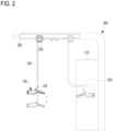
- FIG. 2 is a schematic diagram illustrating a configuration of an electric vehicle charging apparatus including the electric vehicle charging coupler according to one embodiment of the present invention.
- an electric vehicle charging apparatus 200 of the present invention includes a charging main body 210, a canopy 230, an automatic reel 250, a charging cable 240, and a charging coupler 100.
- the charging main body 210 is formed with a predetermined height and installed to stand on the ground.
- a power supply module for supplying charging power is embedded in the charging main body 210. That is, an AC/DC converter (not shown) for converting AC power into DC power is provided in the charging main body 210.
- the DC power converted in the AC/DC converter is supplied to charge a battery of the electric vehicle. Alternatively, DC power converted through a separately provided DC/DC converter may be supplied for charging the electric vehicle.
- a coupler accommodation box 220 is provided in the charging main body 210.
- the charging coupler 100 is accommodated in the coupler accommodation box 220.
- various buttons for controlling operations of the electric vehicle charging apparatus 200 such as a button (not shown) for selecting a charging type of the electric vehicle which will be charged, an emergency button (not shown) for interrupting charging in an emergency situation, and the like, are provided on a front surface of the charging main body 210.
- the canopy 230 is formed to cover an upper side of the charging main body 210 and extends to an area in which the electric vehicle is parked.
- the automatic reel 250 on which the charging cable 240 is wound is installed on the canopy 230. As shown in FIG. 2 , the automatic reel 250 is installed to be reciprocatably transferred between the charging main body 210 and the area in which the electric vehicle is parked.
- the automatic reel 250 is installed to be manually transferred in front of the electric vehicle which is parked or installed to be automatically transferred upon pressing of an automatic reel transfer button (not shown) provided on the front surface of the charging main body 210 by the user.
- the charging cable 240 transmits the DC power supplied from the charging main body 210 to the electric vehicle. Since a high current passes through the charging cable 240 for fast charging and thus high heat is generated, a flow path through which a refrigerant for cooling flows is additionally embedded in the charging cable 240 so that the charging cable 240 becomes thick and heavy.
- the thick and heavy charging cable 240 is easily transferred to a position of the charging port without a large effort due to the automatic reel 250 installed at the upper side. Further, since the charging cable 240 is installed to have a structure which descends from the upper side, the user may easily transfer the charging cable 240 to the charging port of the electric vehicle without lifting or bending the charging cable 240.
- the charging cable 240 is wound on the automatic reel 250.
- the charging coupler 100 descends, and, when the charging cable 240 is wound on the automatic reel 250, the charging coupler 100 ascends.
- the charging coupler 100 is connected to the distal end of the charging cable 240 and has the handle 150 which is formed separately from the cable inlet part 130 through which the charging cable 240 is inserted.
- a configuration of the charging coupler 100 is the same as that described with reference to FIG. 1 , and, since the electric vehicle charging apparatus 200 illustrated in FIG. 2 is dedicated to DC power charging, only the communication terminal of the second port 114 of the charging coupler 100 is used.
- the height adjustment button 152 is provided on the charging coupler 100 so as to move the charging coupler 100 up or down such that a height of the charging port of the electric vehicle is aligned with a height of the charging coupler 100.
- the user operates the height adjustment button 152 to finely adjust the height of the charging coupler 100 by unwinding the charging cable 240 wound on the automatic reel 250 or winding the charging cable 240 on the automatic reel 250. That is, it is possible to finely adjust the height of the charging coupler 100 according to a position of the charging port which is different in height for each electric vehicle by operating the height adjustment button 152.
- FIG. 3 is a diagram comparing the electric vehicle charging coupler according to one embodiment of the present invention with that of the related art.
- FIG. 3A illustrates a conventional electric vehicle charging coupler 10
- FIG. 3B illustrates the electric vehicle charging coupler 100 of the present invention.
- a charging cable 20 is connected to a cable inlet part 11, and the user uses the cable inlet part 11 as a handle. That is, the user should hold the cable inlet part 11 and pull the charging cable 20 to match the conventional charging coupler 10 to the charging port of the electric vehicle.
- the charging cable 20 for fast charging is heavy and lacking in flexibility, it is not easy to bend the charging cable 20 such that it is difficult to handle the charging cable 20 to be wound and the like. Further, when a length of the charging cable 20 is long, the charging cable 20 may fall from a mounting position to a floor and thus may be worn or damaged due to friction with the floor. As described above, when the charging cable 20 is damaged, there is a risk of electric shock and thus a safety problem may occur.
- the handle 150 is formed separately from the cable inlet part 130, and the charging cable 240 is installed to have a structure which descends from the upper side. Therefore, the user may easily mount the charging coupler 100 to the charging port of the electric vehicle by holding the handle 150 only with one hand without bending the charging cable 240 which is heavy and has less flexibility.
- FIG. 4 is a schematic diagram illustrating a configuration of an electric vehicle charging apparatus including an electric vehicle charging coupler according to another embodiment of the present invention.
- an electric vehicle charging apparatus 300 includes a charging main body 310, a mounting bracket 330, a circular rail 340, a driving body 350, a charging cable 360, and a charging coupler 100.
- the charging main body 310 is formed with a predetermined height and installed to stand on the ground.
- a power supply module for supplying charging power is embedded in the charging main body 310.
- a coupler accommodation box 320 is provided in the charging main body 310. When charging is not performed, the charging coupler 100 is accommodated in the coupler accommodation box 320.
- various control buttons for controlling operations of the electric vehicle charging apparatus 300 such as a button (not shown) for selecting a charging type of the electric vehicle which will be charged, an emergency button (not shown) for interrupting charging in an emergency situation, and the like are provided on a front surface of the charging main body 310.
- the mounting bracket 330 is installed on an upper portion of the charging main body 310, and the circular rail 340 is installed on the mounting bracket 330.
- a cable cradle 331 is formed above the mounting bracket 330 such that the charging cable 360 drawn out from the charging main body 310 to the outside is mounted on the cable cradle 331.
- the cable cradle 331 is formed to extend toward a center of the circular rail 340.
- the driving body 350 is movably installed on the circular rail 340 and moved to a stop position of the electric vehicle. That is, the driving body 350 transfers the charging cable 360 to a position of the charging port of the electric vehicle according to the stop position of the electric vehicle.
- the driving body 350 is installed to be manually transferred in front of the electric vehicle which is parked or installed to be automatically transferred upon pressing of an automatic reel transfer button (not shown) provided on the front surface of the charging main body 310 by the user.
- a height adjustment part 351 which vertically ascends or descends is coupled to the driving body 350, and the charging cable 360 is connected to the height adjustment part 351. Therefore, when the height adjustment part 351 descends, the charging coupler 100 connected to a distal end of the charging cable 360 also descends, and, when the height adjustment part 351 ascends, the charging coupler 100 also ascends.
- the charging cable 360 transmits the DC power supplied from the charging main body 310 to the electric vehicle. Since a high current passes through the charging cable 360 for fast charging and thus high heat is generated, a flow path through which a refrigerant for cooling flows is additionally embedded in the charging cable 360 so that the charging cable 360 becomes thick and heavy.
- the thick and heavy charging cable 360 is easily transferred to a position of the charging port without a large effort due to the driving body 350 installed on the circular rail 340. That is, since the charging cable 360 is installed to have a structure which descends from the upper side, the user may easily transfer the charging cable 360 to the charging port of the electric vehicle without lifting or bending the charging cable 240.
- the charging coupler 100 is connected to the distal end of the charging cable 360 and has the handle 150 which is formed separately from the cable inlet part 130 through which the charging cable 360 is inserted.
- a configuration of the charging coupler 100 is the same as that described with reference to FIG. 1 , and, since the electric vehicle charging apparatus 300 illustrated in FIG. 4 is dedicated to DC power charging, only the communication terminal of the second port 114 of the charging coupler 100 is used.
- the height adjustment button 152 is provided on the charging coupler 100 so as to move the charging coupler 100 up or down such that a height of the charging port of the electric vehicle is aligned with a height of the charging coupler 100.
- the user operates the height adjustment button 152 to finely adjust a height of the charging coupler 100 by vertically moving the height adjustment part 351 coupled to the driving body 350 up or down. That is, it is possible to finely adjust the height of the charging coupler 100 according to a position of the charging port which is different in height for each electric vehicle by operating the height adjustment button 152.
- an electric vehicle charging coupler having a handle and an electric vehicle charging apparatus including the same according to the present invention
- a user can easily mount a charging coupler to a charging port of an electric vehicle by easily adjusting a mounting angle of the charging coupler using a handle which is formed separately from a charging cable inlet part.
- the charging cable is installed to have a structure which descends from an upper side, the user can easily transfer the charging cable without a large effort to lift or bend the charging cable.
- a height adjustment button provided on the charging coupler is operated such that the charging coupler can be exactly mounted to the charging port by adjusting a charging height with one hand without handling the heavy and thick charging cables with both hands.
- the electric vehicle charging coupler having a handle and an electric vehicle charging apparatus including the same.
- the electric vehicle charging coupler includes a coupler body having one side on which a charging port to be mounted to a charging port of an electric vehicle is formed to perform charging, a cable inlet part which is formed in an upper portion of the coupler body and into which a charging cable is inserted, and a handle formed to extend from the other side of the coupler body to be held by a hand and provided separately from the cable inlet part. Therefore, the electric vehicle can be easily charged by easily handling the thick and heavy charging cable.
Landscapes
- Engineering & Computer Science (AREA)
- Power Engineering (AREA)
- Transportation (AREA)
- Mechanical Engineering (AREA)
- Charge And Discharge Circuits For Batteries Or The Like (AREA)
- Electric Propulsion And Braking For Vehicles (AREA)
Claims (2)
- Elektrofahrzeug-Ladekupplung (100), die Folgendes umfasst:einen Kupplungskörper (110), der eine Seite aufweist, an der ein Ladeanschluss und ein Verriegelungsmechanismus (116) gebildet sind, wobei der Ladeanschluss an einen Ladeanschluss eines Elektrofahrzeugs montiert werden soll, um Laden durchzuführen, und der Verriegelungsmechanismus (116) die Ladekupplung (100) an dem Ladeanschluss des Elektrofahrzeugs befestigen soll;ein Kabeleinlassteil (130), das in einem oberen Abschnitt des Kupplungskörpers gebildet ist, und in das ein Ladekabel (240) eingesetzt wird, wobei ein Strömungspfad, durch den ein Kältemittel zum Kühlen strömt, in dem Ladekabel (240) eingebettet ist; undeinen Griff (150), der dazu gebildet ist, sich von der anderen Seite des Kupplungskörpers zu erstrecken, um von einer Hand gehalten zu werden, und der separat von dem Kabeleinlassteil bereitgestellt ist,wobei ein Höheneinstellknopf (152) und ein Verriegelungsknopf (154) an dem Griff (150) bereitgestellt sind, wobei der Höheneinstellknopf (152) an einem oberen Abschnitt des Griffs (150) an einer Position gebildet ist, die von einem Daumen betätigbar ist, und der Verriegelungsknopf (154) in einem unteren Abschnitt des Griffs (150) an einer Position gebildet ist, die von einem Zeigefinger betätigbar ist.
- Elektrofahrzeug-Ladekupplung nach Anspruch 1, wobei der Griff Folgendes beinhaltet:den Höheneinstellknopf, der dazu konfiguriert ist, die Ladekupplung nach oben oder unten zu bewegen; undden Verriegelungsknopf, der dazu konfiguriert ist, den Verriegelungsmechanismus zu betätigen, wenn die Ladekupplung an den Ladeanschluss des Elektrofahrzeugs montiert ist.
Applications Claiming Priority (1)
| Application Number | Priority Date | Filing Date | Title |
|---|---|---|---|
| KR1020190101396A KR102205451B1 (ko) | 2019-08-19 | 2019-08-19 | 핸들을 구비한 전기 자동차 충전 커플러 및 이를 포함하는 전기 자동차 충전장치 |
Publications (2)
| Publication Number | Publication Date |
|---|---|
| EP3782848A1 EP3782848A1 (de) | 2021-02-24 |
| EP3782848B1 true EP3782848B1 (de) | 2023-07-19 |
Family
ID=69185370
Family Applications (1)
| Application Number | Title | Priority Date | Filing Date |
|---|---|---|---|
| EP20152612.6A Active EP3782848B1 (de) | 2019-08-19 | 2020-01-20 | Ladekupplung mit griff und elektronische fahrzeugladevorrichtung damit |
Country Status (5)
| Country | Link |
|---|---|
| US (2) | US11691523B2 (de) |
| EP (1) | EP3782848B1 (de) |
| JP (1) | JP6922013B2 (de) |
| KR (1) | KR102205451B1 (de) |
| CN (1) | CN112389223B (de) |
Families Citing this family (6)
| Publication number | Priority date | Publication date | Assignee | Title |
|---|---|---|---|---|
| KR102205451B1 (ko) * | 2019-08-19 | 2021-01-20 | 대영코어텍(주) | 핸들을 구비한 전기 자동차 충전 커플러 및 이를 포함하는 전기 자동차 충전장치 |
| KR102634383B1 (ko) | 2021-11-04 | 2024-02-06 | 대영코어텍(주) | 내구성이 향상된 전기차 충전소켓 |
| US12589664B2 (en) * | 2022-09-14 | 2026-03-31 | Rivian Ip Holdings, Llc | Charge coupler |
| US12594849B2 (en) * | 2023-01-25 | 2026-04-07 | Honda Motor Co., Ltd. | Overhead charging apparatus for electric vehicles |
| EP4406774A1 (de) * | 2023-01-27 | 2024-07-31 | Green Power Co., Ltd. | Ladesystem für ein mobiles elektrofahrzeug auf schienen |
| JP7625182B2 (ja) * | 2023-02-16 | 2025-02-03 | 株式会社タツノ | 充電装置 |
Family Cites Families (68)
| Publication number | Priority date | Publication date | Assignee | Title |
|---|---|---|---|---|
| US635815A (en) * | 1898-09-06 | 1899-10-31 | Cleveland Machine Screw Company | System and apparatus for controlling electric vehicles. |
| JP3042816B2 (ja) * | 1992-12-18 | 2000-05-22 | 矢崎総業株式会社 | 給電コネクタ |
| FR2722614B1 (fr) * | 1994-07-12 | 1996-08-23 | Marechal Sepm | Element mobile de connexion electrique muni d'un cable de liaison et d'une poignee de prehension |
| US9902276B2 (en) * | 2009-09-25 | 2018-02-27 | Control Module, Inc. | Overhead electric vehicle charging system |
| JP5748037B2 (ja) * | 2009-11-04 | 2015-07-15 | 日立オートモティブシステムズメジャメント株式会社 | 懸垂式燃料供給装置 |
| DE102010017458B4 (de) * | 2010-06-18 | 2012-02-16 | Phoenix Contact Gmbh & Co. Kg | Elektrostecker |
| JP2012050288A (ja) * | 2010-08-30 | 2012-03-08 | Auto Network Gijutsu Kenkyusho:Kk | 車両用給電装置 |
| JP5197699B2 (ja) * | 2010-09-09 | 2013-05-15 | 住友電装株式会社 | 充電用コネクタ |
| JP2012090408A (ja) * | 2010-10-19 | 2012-05-10 | Toyota Industries Corp | 車両用充電装置 |
| US20120129378A1 (en) * | 2010-11-19 | 2012-05-24 | Delphi Technologies, Inc. | Battery charger having handle that includes light source that emits light through aperture in handle connector |
| JP2012205312A (ja) * | 2011-03-23 | 2012-10-22 | Toyota Industries Corp | 車両用充電装置 |
| CN103561999B (zh) * | 2011-05-27 | 2016-07-06 | 丰田自动车株式会社 | 车辆 |
| JP5664515B2 (ja) | 2011-09-29 | 2015-02-04 | トヨタ自動車株式会社 | 充電用コネクタおよび充電用機構 |
| JP5648751B2 (ja) * | 2011-10-11 | 2015-01-07 | 日産自動車株式会社 | 充電ポートロック装置 |
| JP6102012B2 (ja) * | 2011-10-24 | 2017-03-29 | パナソニックIpマネジメント株式会社 | 充電制御装置 |
| US9365116B2 (en) * | 2012-07-23 | 2016-06-14 | Ford Global Technologies, Llc | Vehicle recharging station and support devices |
| KR20140067346A (ko) * | 2012-11-26 | 2014-06-05 | 현대자동차주식회사 | 급속 및 완속 충전 일체형 전기자동차 충전 인렛 장치 |
| CN204067715U (zh) * | 2014-06-10 | 2014-12-31 | 深圳巴斯巴科技发展有限公司 | 一种电动汽车充电连接器的自锁装置 |
| CN110015000A (zh) * | 2014-06-27 | 2019-07-16 | 易米充电有限责任公司 | 停车结构 |
| US20170267114A1 (en) * | 2014-07-10 | 2017-09-21 | Control Module, Inc. | Shuttle System for Overhead EVSE |
| US9573478B2 (en) * | 2014-11-14 | 2017-02-21 | Schneider Electric USA, Inc. | EVSE doubler add-on unit |
| DE102015206047A1 (de) * | 2015-04-02 | 2016-10-06 | Volkswagen Aktiengesellschaft | Adapter für ein Ladestecksystem |
| DE102015122038B4 (de) * | 2015-12-17 | 2019-11-28 | Phoenix Contact E-Mobility Gmbh | Steckverbinderteil mit einem Abdeckelement |
| DE102016211335B4 (de) * | 2016-06-24 | 2025-01-02 | Volkswagen Aktiengesellschaft | Verfahren, Adapter, Zusatzsteuergerät und Ladesystem für das elektrische Aufladen von Elektrofahrzeugen |
| CN205970902U (zh) * | 2016-08-15 | 2017-02-22 | 江门市地尔汉宇电器股份有限公司 | 一种带机械锁的防盗电充电枪 |
| DE102017100638A1 (de) * | 2016-10-19 | 2018-04-19 | Elektro-Bauelemente Gmbh | Ladestation für Elektrofahrzeuge |
| EP3312044A1 (de) * | 2016-10-19 | 2018-04-25 | Elektro-Bauelemente GmbH | Ladestation für elektrofahrzeuge |
| KR20180065844A (ko) * | 2016-12-08 | 2018-06-18 | 이건영 | 다세대 주택 전기 자동차 자동 충전 제어 시스템 |
| DE102017103842B4 (de) * | 2017-02-24 | 2018-11-08 | Phoenix Contact E-Mobility Gmbh | Ladestecker mit einem gehäuse und einem zu dem gehäuse anpassbaren griffabschnitt |
| CN106848718A (zh) * | 2017-03-22 | 2017-06-13 | 张仙驰 | 电动汽车快速拔起防盗充电枪 |
| EP3378694B1 (de) * | 2017-03-23 | 2019-08-14 | Vestel Elektronik Sanayi ve Ticaret A.S. | Vorrichtung und verfahren zur bereitstellung einer messung einer leistungskapazität |
| KR20180115963A (ko) | 2017-04-14 | 2018-10-24 | 인우시스템 주식회사 | 전기 자동차용 충전장치 |
| DE102017210808A1 (de) * | 2017-06-27 | 2018-12-27 | Volkswagen Aktiengesellschaft | Ladestation, Anschlussanordnung und Fortbewegungsmittel zur Traktionsenergieübertragung |
| DE102017118300A1 (de) * | 2017-08-11 | 2019-02-14 | Elektro-Bauelemente Gmbh | Ladestation für Elektrofahrzeuge mit einem höhenverstellbar gehaltenen Ladekabelstecker |
| CN107508092A (zh) * | 2017-09-15 | 2017-12-22 | 赵健 | 一种新能源汽车用充电枪 |
| CN107901780A (zh) * | 2017-11-30 | 2018-04-13 | 浙江汇云光电科技有限公司 | 一种直流充电枪 |
| CN108110508A (zh) * | 2017-12-28 | 2018-06-01 | 杜宝兵 | 一种安全型高的新能源汽车充能器 |
| CN109050279A (zh) * | 2017-12-30 | 2018-12-21 | 广州大正新材料科技有限公司 | 一种自动定位的悬挂式充电枪装置及充电方法 |
| CN108128205A (zh) * | 2018-01-10 | 2018-06-08 | 洛阳万山电子科技有限公司 | 一种充电桩收线装置 |
| DE102018100828B4 (de) * | 2018-01-16 | 2023-07-27 | Dr. Ing. H.C. F. Porsche Aktiengesellschaft | Ladestecker für eine Ladesäule und Ladesäule mit einem solchen Stecker |
| DE102018100830A1 (de) * | 2018-01-16 | 2019-07-18 | Dr. Ing. H.C. F. Porsche Aktiengesellschaft | Ladekabel für eine Ladesäule und Ladesäule mit einem solchen Ladekabel |
| DE102018100829A1 (de) * | 2018-01-16 | 2019-07-18 | Dr. Ing. H.C. F. Porsche Aktiengesellschaft | Ladekabel für eine Ladesäule und Ladesäule mit einem solchen Ladekabel |
| KR101895550B1 (ko) * | 2018-03-15 | 2018-10-24 | 대영채비(주) | 전기자동차 충전기용 스마트 무빙 장치 |
| CN108551022B (zh) * | 2018-04-12 | 2019-08-20 | 孟永江 | 一种对开接通式新能源汽车充电桩 |
| CN108454444B (zh) * | 2018-04-12 | 2019-08-20 | 孟永江 | 一种手握插入式高安全新能源汽车充电桩 |
| CN108454443B (zh) * | 2018-04-12 | 2019-09-10 | 赵金林 | 一种新能源汽车充电桩的对开接通方法 |
| CN108718019B (zh) * | 2018-05-31 | 2019-08-30 | 赵生贤 | 一种枪头弹离式充电枪 |
| CN108551055B (zh) * | 2018-05-31 | 2019-09-03 | 乐清市荣盛引进电器有限公司 | 一种带有拖拽保护功能的充电枪 |
| CN108598774B (zh) * | 2018-05-31 | 2020-02-28 | 杨贵珍 | 一种可强制断电的充电枪 |
| CN108909521A (zh) * | 2018-08-23 | 2018-11-30 | 杨树楠 | 一种具有自动卷线功能的电动汽车充电桩 |
| CN109361101B (zh) * | 2018-10-29 | 2019-12-06 | 苏州市相城区黄桥工业园经济发展有限公司 | 一种家用便携式新能源汽车充电装置 |
| DE102019203955B4 (de) * | 2019-03-22 | 2025-02-13 | Volkswagen Ag | Vorrichtung zum automatischen Laden eines Elektrofahrzeugs |
| US11400822B2 (en) * | 2019-05-24 | 2022-08-02 | Abb Schweiz Ag | Suspended charging cable system for electric vehicles |
| EP3771045A1 (de) * | 2019-07-25 | 2021-01-27 | ABB Schweiz AG | Ladeanordnung zum laden von elektrischen fahrzeugen |
| DE102019211373A1 (de) * | 2019-07-30 | 2021-02-04 | Audi Ag | Ladebuchse zum Aufladen eines elektrischen Energiespeichers eines elektrisch betreibbaren Fahrzeugs, Verfahren zum Verschließen und/oder Freigeben einer Ladebuchse und Kraftfahrzeug mit einer Ladebuchse |
| KR102205451B1 (ko) * | 2019-08-19 | 2021-01-20 | 대영코어텍(주) | 핸들을 구비한 전기 자동차 충전 커플러 및 이를 포함하는 전기 자동차 충전장치 |
| CN110481359A (zh) * | 2019-09-23 | 2019-11-22 | 吉林大学 | 一种新能源汽车充电枪 |
| CN110768054B (zh) * | 2019-11-05 | 2021-09-17 | 杭州揽廉科技有限公司 | 一种利用杠杆原理的新能源汽车充电枪 |
| CN111619375B (zh) * | 2020-06-09 | 2021-11-30 | 上海依威能源科技有限公司 | 一种基于互联网的新能源汽车充电接口自通断控制方法 |
| CN111660842A (zh) * | 2020-06-29 | 2020-09-15 | 江苏汉兴电气有限公司 | 一种一体式电动车用充电枪 |
| CN213184832U (zh) * | 2020-09-21 | 2021-05-11 | 中航光电科技股份有限公司 | 一种新能源汽车用交直流充电转换头 |
| CN112193101A (zh) * | 2020-10-20 | 2021-01-08 | 淮北知创风信息科技有限公司 | 一种新能源汽车充电设备 |
| CN112186427B (zh) * | 2020-11-04 | 2021-12-17 | 岱新(上海)电子科技有限公司 | 一种便于插拔的新能源汽车充电插头与插座组合 |
| US11904715B2 (en) * | 2020-11-12 | 2024-02-20 | Rivian Ip Holdings, Llc | Automated plug-in system and method |
| DE102021101528A1 (de) * | 2021-01-25 | 2022-07-28 | Phoenix Contact E-Mobility Gmbh | Hochstrommodul für Ladesteckverbinderteil |
| CN114103694B (zh) * | 2021-11-24 | 2022-09-06 | 云南人民电力电气有限公司 | 一种防触电智能化电动汽车充电桩 |
| CN114530723B (zh) * | 2021-12-30 | 2025-03-28 | 昆山长盈精密技术有限公司 | 充电枪密封外壳及一体式充电枪 |
| CN114883847B (zh) * | 2022-05-18 | 2023-02-03 | 杭州国控电力科技有限公司 | 一种充电桩的插枪组件及充电桩 |
-
2019
- 2019-08-19 KR KR1020190101396A patent/KR102205451B1/ko active Active
-
2020
- 2020-01-20 EP EP20152612.6A patent/EP3782848B1/de active Active
- 2020-01-21 CN CN202010069013.XA patent/CN112389223B/zh active Active
- 2020-02-19 JP JP2020026003A patent/JP6922013B2/ja active Active
- 2020-03-03 US US16/808,318 patent/US11691523B2/en active Active
-
2022
- 2022-04-28 US US17/731,792 patent/US11958371B2/en active Active
Also Published As
| Publication number | Publication date |
|---|---|
| US20210053452A1 (en) | 2021-02-25 |
| JP2021035324A (ja) | 2021-03-01 |
| US11958371B2 (en) | 2024-04-16 |
| JP6922013B2 (ja) | 2021-08-18 |
| EP3782848A1 (de) | 2021-02-24 |
| KR102205451B1 (ko) | 2021-01-20 |
| US20220250492A1 (en) | 2022-08-11 |
| CN112389223B (zh) | 2024-04-05 |
| US11691523B2 (en) | 2023-07-04 |
| CN112389223A (zh) | 2021-02-23 |
Similar Documents
| Publication | Publication Date | Title |
|---|---|---|
| EP3782848B1 (de) | Ladekupplung mit griff und elektronische fahrzeugladevorrichtung damit | |
| CN109715434B (zh) | 用于电动车辆的有线无线兼用的充电装置 | |
| CN106414153B (zh) | 用于电动车辆电池的充电设备和对电动车辆电池进行充电的方法 | |
| US11453291B2 (en) | Contactless charging device, charging system and method for contactlessly charging an energy accumulator of a motor vehicle | |
| EP4249316A1 (de) | Eine ladestation für elektrofahrzeuge | |
| EP4074539A1 (de) | Verfahren und system zur steuerung der verwendung eines kabels oder rohres, insbesondere eines kabels einer ladestation für elektrofahrzeuge | |
| JP2013115915A (ja) | 非接触電力伝送装置及び移動車両 | |
| CN115210103A (zh) | 用于为电动车充电的充电站 | |
| CN111532134A (zh) | 车辆 | |
| CN111516509A (zh) | 车辆 | |
| JPH08331766A (ja) | バッテリ内蔵ヘルメットおよびヘルメット充電装置 | |
| JP2014165943A (ja) | 充電装置 | |
| US20150246617A1 (en) | Power receiving device, power transmitting device, and electric vehicle | |
| JP6070254B2 (ja) | 充電装置 | |
| US20180354377A1 (en) | Charging device for a motor vehicle, motor vehicle, charging arrangement, and operating method | |
| CN121693432A (zh) | 车辆充电装置 | |
| CN218086069U (zh) | 一种太阳能无线充电停机坪装置 | |
| CN216488886U (zh) | 一种放置座和充电插座 | |
| JP6111729B2 (ja) | 充電装置 | |
| CN210852085U (zh) | 无线充电装置及系统 | |
| KR102360826B1 (ko) | 초소형 전기 자동차의 유무선 전력전송 시스템 | |
| CN111002850A (zh) | 电力供应装置和插头保持器 | |
| US12286021B1 (en) | Suspended battery charging station | |
| KR102886171B1 (ko) | 전기자동차용 충전 보조 장치 | |
| CN220401051U (zh) | 一种电源线转接器 |
Legal Events
| Date | Code | Title | Description |
|---|---|---|---|
| PUAI | Public reference made under article 153(3) epc to a published international application that has entered the european phase |
Free format text: ORIGINAL CODE: 0009012 |
|
| STAA | Information on the status of an ep patent application or granted ep patent |
Free format text: STATUS: REQUEST FOR EXAMINATION WAS MADE |
|
| 17P | Request for examination filed |
Effective date: 20200218 |
|
| AK | Designated contracting states |
Kind code of ref document: A1 Designated state(s): AL AT BE BG CH CY CZ DE DK EE ES FI FR GB GR HR HU IE IS IT LI LT LU LV MC MK MT NL NO PL PT RO RS SE SI SK SM TR |
|
| AX | Request for extension of the european patent |
Extension state: BA ME |
|
| STAA | Information on the status of an ep patent application or granted ep patent |
Free format text: STATUS: EXAMINATION IS IN PROGRESS |
|
| 17Q | First examination report despatched |
Effective date: 20220707 |
|
| GRAP | Despatch of communication of intention to grant a patent |
Free format text: ORIGINAL CODE: EPIDOSNIGR1 |
|
| STAA | Information on the status of an ep patent application or granted ep patent |
Free format text: STATUS: GRANT OF PATENT IS INTENDED |
|
| INTG | Intention to grant announced |
Effective date: 20230314 |
|
| GRAS | Grant fee paid |
Free format text: ORIGINAL CODE: EPIDOSNIGR3 |
|
| GRAA | (expected) grant |
Free format text: ORIGINAL CODE: 0009210 |
|
| STAA | Information on the status of an ep patent application or granted ep patent |
Free format text: STATUS: THE PATENT HAS BEEN GRANTED |
|
| AK | Designated contracting states |
Kind code of ref document: B1 Designated state(s): AL AT BE BG CH CY CZ DE DK EE ES FI FR GB GR HR HU IE IS IT LI LT LU LV MC MK MT NL NO PL PT RO RS SE SI SK SM TR |
|
| REG | Reference to a national code |
Ref country code: GB Ref legal event code: FG4D |
|
| REG | Reference to a national code |
Ref country code: CH Ref legal event code: EP |
|
| REG | Reference to a national code |
Ref country code: DE Ref legal event code: R096 Ref document number: 602020013897 Country of ref document: DE |
|
| REG | Reference to a national code |
Ref country code: IE Ref legal event code: FG4D |
|
| REG | Reference to a national code |
Ref country code: LT Ref legal event code: MG9D |
|
| REG | Reference to a national code |
Ref country code: NL Ref legal event code: MP Effective date: 20230719 |
|
| REG | Reference to a national code |
Ref country code: AT Ref legal event code: MK05 Ref document number: 1589142 Country of ref document: AT Kind code of ref document: T Effective date: 20230719 |
|
| PG25 | Lapsed in a contracting state [announced via postgrant information from national office to epo] |
Ref country code: NL Free format text: LAPSE BECAUSE OF FAILURE TO SUBMIT A TRANSLATION OF THE DESCRIPTION OR TO PAY THE FEE WITHIN THE PRESCRIBED TIME-LIMIT Effective date: 20230719 |
|
| PG25 | Lapsed in a contracting state [announced via postgrant information from national office to epo] |
Ref country code: GR Free format text: LAPSE BECAUSE OF FAILURE TO SUBMIT A TRANSLATION OF THE DESCRIPTION OR TO PAY THE FEE WITHIN THE PRESCRIBED TIME-LIMIT Effective date: 20231020 |
|
| PG25 | Lapsed in a contracting state [announced via postgrant information from national office to epo] |
Ref country code: IS Free format text: LAPSE BECAUSE OF FAILURE TO SUBMIT A TRANSLATION OF THE DESCRIPTION OR TO PAY THE FEE WITHIN THE PRESCRIBED TIME-LIMIT Effective date: 20231119 |
|
| PG25 | Lapsed in a contracting state [announced via postgrant information from national office to epo] |
Ref country code: SE Free format text: LAPSE BECAUSE OF FAILURE TO SUBMIT A TRANSLATION OF THE DESCRIPTION OR TO PAY THE FEE WITHIN THE PRESCRIBED TIME-LIMIT Effective date: 20230719 Ref country code: RS Free format text: LAPSE BECAUSE OF FAILURE TO SUBMIT A TRANSLATION OF THE DESCRIPTION OR TO PAY THE FEE WITHIN THE PRESCRIBED TIME-LIMIT Effective date: 20230719 Ref country code: PT Free format text: LAPSE BECAUSE OF FAILURE TO SUBMIT A TRANSLATION OF THE DESCRIPTION OR TO PAY THE FEE WITHIN THE PRESCRIBED TIME-LIMIT Effective date: 20231120 Ref country code: NO Free format text: LAPSE BECAUSE OF FAILURE TO SUBMIT A TRANSLATION OF THE DESCRIPTION OR TO PAY THE FEE WITHIN THE PRESCRIBED TIME-LIMIT Effective date: 20231019 Ref country code: LV Free format text: LAPSE BECAUSE OF FAILURE TO SUBMIT A TRANSLATION OF THE DESCRIPTION OR TO PAY THE FEE WITHIN THE PRESCRIBED TIME-LIMIT Effective date: 20230719 Ref country code: LT Free format text: LAPSE BECAUSE OF FAILURE TO SUBMIT A TRANSLATION OF THE DESCRIPTION OR TO PAY THE FEE WITHIN THE PRESCRIBED TIME-LIMIT Effective date: 20230719 Ref country code: IS Free format text: LAPSE BECAUSE OF FAILURE TO SUBMIT A TRANSLATION OF THE DESCRIPTION OR TO PAY THE FEE WITHIN THE PRESCRIBED TIME-LIMIT Effective date: 20231119 Ref country code: HR Free format text: LAPSE BECAUSE OF FAILURE TO SUBMIT A TRANSLATION OF THE DESCRIPTION OR TO PAY THE FEE WITHIN THE PRESCRIBED TIME-LIMIT Effective date: 20230719 Ref country code: GR Free format text: LAPSE BECAUSE OF FAILURE TO SUBMIT A TRANSLATION OF THE DESCRIPTION OR TO PAY THE FEE WITHIN THE PRESCRIBED TIME-LIMIT Effective date: 20231020 Ref country code: FI Free format text: LAPSE BECAUSE OF FAILURE TO SUBMIT A TRANSLATION OF THE DESCRIPTION OR TO PAY THE FEE WITHIN THE PRESCRIBED TIME-LIMIT Effective date: 20230719 Ref country code: AT Free format text: LAPSE BECAUSE OF FAILURE TO SUBMIT A TRANSLATION OF THE DESCRIPTION OR TO PAY THE FEE WITHIN THE PRESCRIBED TIME-LIMIT Effective date: 20230719 |
|
| PG25 | Lapsed in a contracting state [announced via postgrant information from national office to epo] |
Ref country code: PL Free format text: LAPSE BECAUSE OF FAILURE TO SUBMIT A TRANSLATION OF THE DESCRIPTION OR TO PAY THE FEE WITHIN THE PRESCRIBED TIME-LIMIT Effective date: 20230719 |
|
| REG | Reference to a national code |
Ref country code: DE Ref legal event code: R097 Ref document number: 602020013897 Country of ref document: DE |
|
| PG25 | Lapsed in a contracting state [announced via postgrant information from national office to epo] |
Ref country code: ES Free format text: LAPSE BECAUSE OF FAILURE TO SUBMIT A TRANSLATION OF THE DESCRIPTION OR TO PAY THE FEE WITHIN THE PRESCRIBED TIME-LIMIT Effective date: 20230719 |
|
| PG25 | Lapsed in a contracting state [announced via postgrant information from national office to epo] |
Ref country code: SM Free format text: LAPSE BECAUSE OF FAILURE TO SUBMIT A TRANSLATION OF THE DESCRIPTION OR TO PAY THE FEE WITHIN THE PRESCRIBED TIME-LIMIT Effective date: 20230719 Ref country code: RO Free format text: LAPSE BECAUSE OF FAILURE TO SUBMIT A TRANSLATION OF THE DESCRIPTION OR TO PAY THE FEE WITHIN THE PRESCRIBED TIME-LIMIT Effective date: 20230719 Ref country code: ES Free format text: LAPSE BECAUSE OF FAILURE TO SUBMIT A TRANSLATION OF THE DESCRIPTION OR TO PAY THE FEE WITHIN THE PRESCRIBED TIME-LIMIT Effective date: 20230719 Ref country code: EE Free format text: LAPSE BECAUSE OF FAILURE TO SUBMIT A TRANSLATION OF THE DESCRIPTION OR TO PAY THE FEE WITHIN THE PRESCRIBED TIME-LIMIT Effective date: 20230719 Ref country code: DK Free format text: LAPSE BECAUSE OF FAILURE TO SUBMIT A TRANSLATION OF THE DESCRIPTION OR TO PAY THE FEE WITHIN THE PRESCRIBED TIME-LIMIT Effective date: 20230719 Ref country code: CZ Free format text: LAPSE BECAUSE OF FAILURE TO SUBMIT A TRANSLATION OF THE DESCRIPTION OR TO PAY THE FEE WITHIN THE PRESCRIBED TIME-LIMIT Effective date: 20230719 Ref country code: SK Free format text: LAPSE BECAUSE OF FAILURE TO SUBMIT A TRANSLATION OF THE DESCRIPTION OR TO PAY THE FEE WITHIN THE PRESCRIBED TIME-LIMIT Effective date: 20230719 |
|
| PLBE | No opposition filed within time limit |
Free format text: ORIGINAL CODE: 0009261 |
|
| STAA | Information on the status of an ep patent application or granted ep patent |
Free format text: STATUS: NO OPPOSITION FILED WITHIN TIME LIMIT |
|
| PG25 | Lapsed in a contracting state [announced via postgrant information from national office to epo] |
Ref country code: IT Free format text: LAPSE BECAUSE OF FAILURE TO SUBMIT A TRANSLATION OF THE DESCRIPTION OR TO PAY THE FEE WITHIN THE PRESCRIBED TIME-LIMIT Effective date: 20230719 |
|
| 26N | No opposition filed |
Effective date: 20240422 |
|
| PG25 | Lapsed in a contracting state [announced via postgrant information from national office to epo] |
Ref country code: SI Free format text: LAPSE BECAUSE OF FAILURE TO SUBMIT A TRANSLATION OF THE DESCRIPTION OR TO PAY THE FEE WITHIN THE PRESCRIBED TIME-LIMIT Effective date: 20230719 |
|
| PG25 | Lapsed in a contracting state [announced via postgrant information from national office to epo] |
Ref country code: MC Free format text: LAPSE BECAUSE OF FAILURE TO SUBMIT A TRANSLATION OF THE DESCRIPTION OR TO PAY THE FEE WITHIN THE PRESCRIBED TIME-LIMIT Effective date: 20230719 |
|
| PG25 | Lapsed in a contracting state [announced via postgrant information from national office to epo] |
Ref country code: MC Free format text: LAPSE BECAUSE OF FAILURE TO SUBMIT A TRANSLATION OF THE DESCRIPTION OR TO PAY THE FEE WITHIN THE PRESCRIBED TIME-LIMIT Effective date: 20230719 |
|
| REG | Reference to a national code |
Ref country code: CH Ref legal event code: PL |
|
| PG25 | Lapsed in a contracting state [announced via postgrant information from national office to epo] |
Ref country code: LU Free format text: LAPSE BECAUSE OF NON-PAYMENT OF DUE FEES Effective date: 20240120 |
|
| PG25 | Lapsed in a contracting state [announced via postgrant information from national office to epo] |
Ref country code: LU Free format text: LAPSE BECAUSE OF NON-PAYMENT OF DUE FEES Effective date: 20240120 |
|
| PG25 | Lapsed in a contracting state [announced via postgrant information from national office to epo] |
Ref country code: BE Free format text: LAPSE BECAUSE OF NON-PAYMENT OF DUE FEES Effective date: 20240131 |
|
| PG25 | Lapsed in a contracting state [announced via postgrant information from national office to epo] |
Ref country code: CH Free format text: LAPSE BECAUSE OF NON-PAYMENT OF DUE FEES Effective date: 20240131 |
|
| PG25 | Lapsed in a contracting state [announced via postgrant information from national office to epo] |
Ref country code: CH Free format text: LAPSE BECAUSE OF NON-PAYMENT OF DUE FEES Effective date: 20240131 Ref country code: BE Free format text: LAPSE BECAUSE OF NON-PAYMENT OF DUE FEES Effective date: 20240131 |
|
| REG | Reference to a national code |
Ref country code: BE Ref legal event code: MM Effective date: 20240131 |
|
| PG25 | Lapsed in a contracting state [announced via postgrant information from national office to epo] |
Ref country code: BG Free format text: LAPSE BECAUSE OF FAILURE TO SUBMIT A TRANSLATION OF THE DESCRIPTION OR TO PAY THE FEE WITHIN THE PRESCRIBED TIME-LIMIT Effective date: 20230719 |
|
| PG25 | Lapsed in a contracting state [announced via postgrant information from national office to epo] |
Ref country code: BG Free format text: LAPSE BECAUSE OF FAILURE TO SUBMIT A TRANSLATION OF THE DESCRIPTION OR TO PAY THE FEE WITHIN THE PRESCRIBED TIME-LIMIT Effective date: 20230719 |
|
| PG25 | Lapsed in a contracting state [announced via postgrant information from national office to epo] |
Ref country code: IE Free format text: LAPSE BECAUSE OF NON-PAYMENT OF DUE FEES Effective date: 20240120 |
|
| PG25 | Lapsed in a contracting state [announced via postgrant information from national office to epo] |
Ref country code: IE Free format text: LAPSE BECAUSE OF NON-PAYMENT OF DUE FEES Effective date: 20240120 |
|
| PG25 | Lapsed in a contracting state [announced via postgrant information from national office to epo] |
Ref country code: CY Free format text: LAPSE BECAUSE OF FAILURE TO SUBMIT A TRANSLATION OF THE DESCRIPTION OR TO PAY THE FEE WITHIN THE PRESCRIBED TIME-LIMIT; INVALID AB INITIO Effective date: 20200120 |
|
| PG25 | Lapsed in a contracting state [announced via postgrant information from national office to epo] |
Ref country code: HU Free format text: LAPSE BECAUSE OF FAILURE TO SUBMIT A TRANSLATION OF THE DESCRIPTION OR TO PAY THE FEE WITHIN THE PRESCRIBED TIME-LIMIT; INVALID AB INITIO Effective date: 20200120 |
|
| PG25 | Lapsed in a contracting state [announced via postgrant information from national office to epo] |
Ref country code: TR Free format text: LAPSE BECAUSE OF FAILURE TO SUBMIT A TRANSLATION OF THE DESCRIPTION OR TO PAY THE FEE WITHIN THE PRESCRIBED TIME-LIMIT Effective date: 20230719 |
|
| PGFP | Annual fee paid to national office [announced via postgrant information from national office to epo] |
Ref country code: GB Payment date: 20260115 Year of fee payment: 7 |
|
| PGFP | Annual fee paid to national office [announced via postgrant information from national office to epo] |
Ref country code: DE Payment date: 20260116 Year of fee payment: 7 |
|
| PGFP | Annual fee paid to national office [announced via postgrant information from national office to epo] |
Ref country code: FR Payment date: 20260113 Year of fee payment: 7 |