EP3782931A1 - Stapellageranordnung - Google Patents
Stapellageranordnung Download PDFInfo
- Publication number
- EP3782931A1 EP3782931A1 EP19193380.3A EP19193380A EP3782931A1 EP 3782931 A1 EP3782931 A1 EP 3782931A1 EP 19193380 A EP19193380 A EP 19193380A EP 3782931 A1 EP3782931 A1 EP 3782931A1
- Authority
- EP
- European Patent Office
- Prior art keywords
- opening
- storage arrangement
- arrangement according
- stacking storage
- carrier element
- Prior art date
- Legal status (The legal status is an assumption and is not a legal conclusion. Google has not performed a legal analysis and makes no representation as to the accuracy of the status listed.)
- Granted
Links
Images
Classifications
-
- B—PERFORMING OPERATIONS; TRANSPORTING
- B65—CONVEYING; PACKING; STORING; HANDLING THIN OR FILAMENTARY MATERIAL
- B65G—TRANSPORT OR STORAGE DEVICES, e.g. CONVEYORS FOR LOADING OR TIPPING, SHOP CONVEYOR SYSTEMS OR PNEUMATIC TUBE CONVEYORS
- B65G1/00—Storing articles, individually or in orderly arrangement, in warehouses or magazines
- B65G1/02—Storage devices
- B65G1/04—Storage devices mechanical
- B65G1/0471—Storage devices mechanical with access from beneath
-
- A—HUMAN NECESSITIES
- A47—FURNITURE; DOMESTIC ARTICLES OR APPLIANCES; COFFEE MILLS; SPICE MILLS; SUCTION CLEANERS IN GENERAL
- A47B—TABLES; DESKS; OFFICE FURNITURE; CABINETS; DRAWERS; GENERAL DETAILS OF FURNITURE
- A47B87/00—Sectional furniture, i.e. combinations of complete furniture units, e.g. assemblies of furniture units of the same kind such as linkable cabinets, tables, racks or shelf units
- A47B87/02—Sectional furniture, i.e. combinations of complete furniture units, e.g. assemblies of furniture units of the same kind such as linkable cabinets, tables, racks or shelf units stackable ; stackable and linkable
- A47B87/0207—Stackable racks, trays or shelf units
- A47B87/0261—Independent trays
-
- B—PERFORMING OPERATIONS; TRANSPORTING
- B65—CONVEYING; PACKING; STORING; HANDLING THIN OR FILAMENTARY MATERIAL
- B65D—CONTAINERS FOR STORAGE OR TRANSPORT OF ARTICLES OR MATERIALS, e.g. BAGS, BARRELS, BOTTLES, BOXES, CANS, CARTONS, CRATES, DRUMS, JARS, TANKS, HOPPERS, FORWARDING CONTAINERS; ACCESSORIES, CLOSURES, OR FITTINGS THEREFOR; PACKAGING ELEMENTS; PACKAGES
- B65D61/00—External frames or supports adapted to be assembled around, or applied to, articles
-
- A—HUMAN NECESSITIES
- A47—FURNITURE; DOMESTIC ARTICLES OR APPLIANCES; COFFEE MILLS; SPICE MILLS; SUCTION CLEANERS IN GENERAL
- A47B—TABLES; DESKS; OFFICE FURNITURE; CABINETS; DRAWERS; GENERAL DETAILS OF FURNITURE
- A47B87/00—Sectional furniture, i.e. combinations of complete furniture units, e.g. assemblies of furniture units of the same kind such as linkable cabinets, tables, racks or shelf units
- A47B87/02—Sectional furniture, i.e. combinations of complete furniture units, e.g. assemblies of furniture units of the same kind such as linkable cabinets, tables, racks or shelf units stackable ; stackable and linkable
- A47B87/0207—Stackable racks, trays or shelf units
- A47B87/0246—Shelves stackable by means of separate vertical distance-holders therebetween
-
- B—PERFORMING OPERATIONS; TRANSPORTING
- B65—CONVEYING; PACKING; STORING; HANDLING THIN OR FILAMENTARY MATERIAL
- B65D—CONTAINERS FOR STORAGE OR TRANSPORT OF ARTICLES OR MATERIALS, e.g. BAGS, BARRELS, BOTTLES, BOXES, CANS, CARTONS, CRATES, DRUMS, JARS, TANKS, HOPPERS, FORWARDING CONTAINERS; ACCESSORIES, CLOSURES, OR FITTINGS THEREFOR; PACKAGING ELEMENTS; PACKAGES
- B65D85/00—Containers, packaging elements or packages, specially adapted for particular articles or materials
- B65D85/62—Containers, packaging elements or packages, specially adapted for particular articles or materials for stacks of articles; for special arrangements of groups of articles
-
- B—PERFORMING OPERATIONS; TRANSPORTING
- B65—CONVEYING; PACKING; STORING; HANDLING THIN OR FILAMENTARY MATERIAL
- B65G—TRANSPORT OR STORAGE DEVICES, e.g. CONVEYORS FOR LOADING OR TIPPING, SHOP CONVEYOR SYSTEMS OR PNEUMATIC TUBE CONVEYORS
- B65G1/00—Storing articles, individually or in orderly arrangement, in warehouses or magazines
- B65G1/02—Storage devices
-
- B—PERFORMING OPERATIONS; TRANSPORTING
- B65—CONVEYING; PACKING; STORING; HANDLING THIN OR FILAMENTARY MATERIAL
- B65G—TRANSPORT OR STORAGE DEVICES, e.g. CONVEYORS FOR LOADING OR TIPPING, SHOP CONVEYOR SYSTEMS OR PNEUMATIC TUBE CONVEYORS
- B65G59/00—De-stacking of articles
- B65G59/06—De-stacking from the bottom of the stack
- B65G59/061—De-stacking from the bottom of the stack articles being separated substantially along the axis of the stack
- B65G59/062—De-stacking from the bottom of the stack articles being separated substantially along the axis of the stack by means of reciprocating or oscillating escapement-like mechanisms
Definitions
- the present invention relates to a stacking storage arrangement which has a frame with a plurality of container receiving spaces which each have an opening at their lower end, wherein a latch arrangement is arranged at at least one opening which has at least one latch unit with a retaining latch that is positioned between a locking position and a Release position is movable.
- Such a stacking storage arrangement is for example from EP 2 982 624 B1 known.
- containers can be stored which are stacked on top of one another and thus form stacks.
- the stacks can be arranged relatively closely adjacent to one another, for example in the form of a matrix with rows and columns.
- a container can either be brought into the stack from above and also removed from the top, or it can be brought into the stack from below and removed from below.
- the container is stored from below and also removed from below.
- a loading space is provided below the container receiving spaces, in which a loading vehicle can move.
- the loading vehicle can, for example, when it is loaded with a container outside the stacking storage arrangement, transport it to a predetermined stack, lift the container there until it comes to rest against the bottom container of this stack and then lift the container with the stack resting on it. This raising continues until the new containers to be stored has passed the latch assembly.
- the latch arrangement can be opened by the container to be stored.
- the holding pawls snap into place on the container and hold the container with the stack of other containers resting on it at the desired distance from the floor or another contact surface, so that the Loading space can be kept free of containers.
- the retaining pawls form a replacement or maintenance part. At the same time, they are an essential element for the function. Accordingly, it is important for economical operation of the stack storage arrangement that maintenance times can be kept short.
- the invention is based on the object of keeping times for maintenance and servicing short.
- this object is achieved in that the retaining pawl is exchangeable from the inside of the opening.
- the retaining pawl is preferably arranged in a carrier element which is releasably fastened in the frame.
- a holding pawl unit is used here, in which the holding pawl is arranged in a carrier element. This unit can easily be replaced in the event of damage or maintenance. Such a replacement can take place in a relatively short time, so that one the maintenance or servicing of the stacking storage arrangement can in any case be carried out relatively quickly in this area.
- the opening preferably has two longitudinal sides and two transverse sides and the retaining pawl can be pivoted about an axis which includes an angle of less than 90 ° with both a longitudinal side and a transverse side.
- the axis preferably encloses an angle of approximately 45 ° with both sides, that is to say with the longitudinal side and the transverse side.
- the retaining pawl therefore acts from one corner into the opening.
- the holding pawl acts on a corner of the container.
- a container usually has the greatest stability in the corner. Accordingly, the load-bearing capacity of the container is made large, so that a larger number of further containers can be stacked above the lowest container.
- the axis is preferably mounted on two support flanges running perpendicular to the axis. This facilitates the manufacture of the carrier element. You can decouple the support flanges from areas with which the carrier element is attached to the frame.
- the opening is preferably formed in a frame which forms part of the frame, the carrier element being arranged in a recess in the frame.
- the carrier element can then be supported in the frame, which results in high mechanical stability.
- installation space is saved because the carrier element can be at least partially sunk into the frame.
- the recess is preferably designed as a through opening.
- the carrier element can thus largely disappear in the recess without the frame having to be designed with an excessively thick wall.
- the carrier element is designed as an angular element which has a first leg that is aligned parallel to one side of the opening and a second leg that is aligned parallel to another side adjoining the side. This allows you to arrange the carrier element in the corner of the opening and mount the two legs parallel to the edge of the opening.
- the carrier element is preferably accessible from inside the opening. If a repair is required, the carrier element can simply be removed from the inside of the opening and another carrier element with a retaining pawl attached to it can be inserted. This makes the repair easier.
- the carrier element is preferably connected to an inside of the opening. You can solve this connection from the inside of the opening, so that only work is required below a single container receiving space. However, it is not necessary to intervene from areas below other container receiving spaces.
- the retaining pawl is preferably designed as a two-armed lever with a first arm which is directed into the opening and a second arm which is directed away from the opening, a stop being provided on the carrier element on which the second arm strikes when the first arm forms an angle in the range from minus 15 ° to plus 15 ° with the horizontal.
- the first arm can therefore protrude relatively far into the opening in order to hold a container.
- the second arm preferably extends in a straight line to the first arm, which facilitates the production of the retaining pawl.
- the stop is preferably formed by a wall section of the carrier element. An additional element is not required, which makes manufacturing inexpensive.
- the retaining pawl is preferably connected to a torsion spring arrangement which applies a force to the second arm of the retaining pawl in the direction of the stop. This ensures that the holding pawl, when no other forces are present, is always pivoted into a holding position in which it can support a container.
- the holding pawl preferably has part of a sensor arrangement with which a position of the holding pawl can be detected. You can then determine in a relatively simple manner whether the holding pawl is in the holding or blocking position in which it secures a container against moving further downwards. Should the sensor arrangement determine that this is not the case, then, for example, a further lowering of a container can be prevented in order to avoid a dangerous situation.
- the part of the sensor arrangement is preferably designed as a reflector.
- a part of the sensor arrangement can then, for example, direct a light beam into the area in which the reflector is arranged when the holding pawl is in the holding or blocking position.
- the reflector then reflects the light beam back to the receiver.
- the sensor arrangement can determine that the holding pawl has been pivoted into the holding or locking position. If the receiver does not detect the light beam, this is a sign that the retaining pawl is not in the desired position.
- the carrier element is preferably designed as a cast part.
- a cast part can be manufactured inexpensively and at the same time has the required mechanical stability.
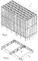
- Fig. 1 shows a schematic representation of a stacking store 1 in which a plurality of containers 2 are arranged.
- the containers 2 are arranged in stacks in the form of a matrix with rows and columns. In the present embodiment, five stacks are arranged next to one another and sixteen stacks one behind the other.
- a loading space 3 is arranged below the stacks of containers 2, through which containers can be stored in the stacking storage arrangement 1 and removed from the stacking storage arrangement 1.
- the containers 2 are arranged in container receiving spaces.
- a frame 4 is arranged between the loading space 3 and the container receiving spaces.
- the frame 4 forms part of a frame.
- the frame also has uprights 5, which can be connected to one another by transverse struts 6 and longitudinal struts 7.
- the frame 4 is supported by supports 8 on the floor or another contact surface.
- the frame 4 is composed of a plurality of modules 9, which can be connected to one another in the longitudinal direction and in the transverse direction of the stacking storage arrangement 1, for example by means of screws or rivets.
- Each module forms an opening 19 through which a container 2 can be introduced into a container receiving space or removed from the container receiving space.
- Fig. 2 shows two such modules 9, each of which has an opening 19. However, it is also possible to use modules that have more than one opening 19. For example, modules with two, three, four or five openings are possible.
- the modules 9 are preferably designed as cast parts.
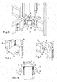
- Fig. 3 shows part of a module 9 with stands 5 located thereon Fig. 3 a latch unit 10, which is in the Figures 4 to 6 is shown enlarged.
- the pawl unit 10 has a holding pawl 11 which is located between a in Fig. 4 shown locked position and one in Fig. 5 shown release position is movable.
- the movement of the holding pawl 11 takes place by pivoting about an axis 12 which is shown in FIG Fig. 6 is shown in dashed lines.
- Two springs 13, preferably torsion springs or torsion springs, are provided in order to load the holding pawl 11 with a force or a moment in the direction of the locking position.
- the center of gravity of the holding pawl 11 is preferably arranged in such a way that a movement into the blocking position takes place automatically by means of gravity.
- the pawl unit has a carrier element 14 on which the retaining pawl 11 is pivotably arranged.
- the carrier element 14 is detachably arranged in the frame, more precisely in the frame, namely on the inside of the opening 19.
- the carrier element 14 and thus the pawl unit 10 can therefore be mounted or exchanged from the inside of the opening 19.
- the carrier element 14 is mounted in a recess 15 in the frame.
- the recess 15 is designed as a through opening in the frame. How to get in Fig. 2 can be seen, the recess 15 is designed as a through opening in the module 9.
- the carrier element 14 can thus largely be countersunk in the frame, in the present case in the module 9, and only protrudes slightly from the frame.
- the carrier element 14 is designed as an angle element which has two legs, namely a first leg 16 which is aligned parallel to one side of the opening 19, and a second leg 17 which is parallel to another side of the adjoining this side Opening 19 is aligned.
- the two legs 16, 17 enclose an angle of approximately 90 °.
- the support flanges 18, 20 protrude from the legs 16, 17 into the opening 19.
- the support flanges 18, 20 run essentially parallel to the longitudinal extent of the holding pawl 11.
- the holding pawl 11 is pivotably mounted in the support flanges 18, 20.
- the support flanges 18, 20 run perpendicular to the axis 12.
- the first leg 16 has a first fastening area 21 and the second leg 17 has a second fastening area 22.
- the fastening areas 21, 22 rest on the frame, in the present case on the module 9, from the inside.
- the fastening areas 21, 22 have bores 23 through which screw bolts can be passed in order to fasten the carrier element 14 to the frame.
- the carrier element is thus connected to the inside of the opening 19.
- the holding pawl 11 is designed as a two-armed lever with a first arm 24, which is directed into the opening 19, and a second arm 25, which is directed away from the opening 19.
- a stop is provided on the support element 14, against which the second arm 25 strikes when the first arm 24, more precisely the upper side of the first arm 24 in the direction of gravity, encloses an angle in the range from minus 15 ° to plus 15 ° with the horizontal . This ensures that the holding pawl is in the locked or holding position ( Fig. 4 ) protrudes as far as possible into the opening 19 and a container 2, which is held by the holding pawls 11 in the four corners of the opening 19, can be reliably held in the opening 19 regardless of its exact alignment.
- the stop is formed by the carrier element 14, which for this purpose can have a recess (not shown in detail) on its underside.
- a reflector 26 is arranged on the underside of the first arm 24.
- the reflector 26 forms part of a sensor arrangement, otherwise not shown in detail, with which a position of the holding pawl 11 can be detected.
- the sensor arrangement can, for example, be provided with a light source whose beam is directed upwards. When the retaining pawl 11 is in the locking position, light is then reflected back into the vicinity of the light source and can be detected there. If this is the case, this is an indication that the retaining pawl 11 is in the locked position. If this is not the case, this indicates that the holding pawl 11 is not in the blocking position and accordingly cannot hold a container reliably.
- the sensor arrangement can transmit a corresponding signal to a control device, which then on the one hand triggers a fault message or error message and on the other hand prevents a container or a stack of containers from lowering further.
- the remaining part of the sensor arrangement can be arranged in the frame. However, it is also possible to arrange further elements of the sensor arrangement on a loading vehicle with which a container can be moved into the stacking storage arrangement or removed from the stacking storage arrangement.
- the carrier element 14 is preferably designed as a cast part. It can be manufactured inexpensively and requires only little post-processing effort.
- the container does not necessarily have to be closed on all sides. It can also have openings as long as it is stackable.
Landscapes
- Engineering & Computer Science (AREA)
- Mechanical Engineering (AREA)
- Stackable Containers (AREA)
- Details Of Rigid Or Semi-Rigid Containers (AREA)
- Warehouses Or Storage Devices (AREA)
Abstract
Description
- Die vorliegende Erfindung betrifft eine Stapellageranordnung, die ein Gestell mit mehreren Behälteraufnahmeräumen aufweist, die an ihrem unteren Ende jeweils eine Öffnung aufweisen, wobei an mindestens einer Öffnung eine Klinkenanordnung angeordnet ist, die mindestens eine Klinkeneinheit mit einer Halteklinke aufweist, die zwischen einer Sperrstellung und einer Freigabestellung bewegbar ist.
- Eine derartige Stapellageranordnung ist beispielsweise aus
EP 2 982 624 B1 bekannt. - In einer derartigen Stapellageranordnung können Behälter gelagert werden, die aufeinandergestapelt sind und somit Stapel bilden. Die Stapel können relativ dicht benachbart zueinander angeordnet werden, beispielsweise in Form einer Matrix mit Reihen und Spalten.
- Prinzipiell kann man einen Behälter entweder von oben in den Stapel einbringen und ihn ebenfalls oben entnehmen, oder man kann ihn von unten in den Stapel einbringen und von unten entnehmen. In der vorliegenden Stapellageranordnung wird der Behälter von unten eingelagert und ebenfalls von unten entnommen.
- Um dies bewerkstelligen zu können, ist unterhalb der Behälteraufnahmeräume ein Beschickungsraum vorgesehen, in dem sich ein Beschickungsfahrzeug bewegen kann. Das Beschickungsfahrzeug kann, wenn es beispielsweise außerhalb der Stapellageranordnung mit einem Behälter beladen wird, diesen zu einem vorbestimmten Stapel transportieren, den Behälter dort anheben, bis er an den untersten Behälter dieses Stapels zur Anlage kommt und dann den Behälter mit dem darauf ruhenden Stapel anheben. Dieses Anheben erfolgt solange, bis der neu einzulagernde Behälter an der Klinkenanordnung vorbeigelaufen ist. Die Klinkenanordnung kann dabei durch den einzulagernden Behälter geöffnet werden. Wenn der einzulagernde Behälter mit dem darauf ruhenden Stapel von weiteren Behältern wieder abgesenkt wird, dann rasten die Halteklinken an dem Behälter ein und halten den Behälter mit dem darauf ruhenden Stapel von anderen Behältern in dem gewünschten Abstand vom Fußboden oder einer anderen Aufstandsfläche, so dass der Beschickungsraum frei von Behältern gehalten werden kann.
- Die Halteklinken bilden ein Ersatz- oder Wartungsteil. Gleichzeitig sind sie ein für die Funktion wesentliches Element. Dementsprechend ist es für einen wirtschaftlichen Betrieb der Stapellageranordnung wichtig, dass Wartungszeiten kurzgehalten werden können.
- Der Erfindung liegt die Aufgabe zugrunde, Zeiten für Wartung und Instandhaltung kurz zu halten.
- Diese Aufgabe wird bei einer Stapellageranordnung der eingangs genannten Art dadurch gelöst, dass die Halteklinke von der Innenseite der Öffnung aus austauschbar ist.
- Man benötigt also lediglich einen Zugang zu der Öffnung, wenn ein Austausch der Halteklinke erforderlich sein sollte. Es ist nicht erforderlich, größere Teile der Stapellageranordnung auszubauen. Jeder Behälteraufnahmeraum kann getrennt von anderen Behälteraufnahmeräumen gewartet und instand gehalten werden.
- Bevorzugterweise ist die Halteklinke in einem Trägerelement angeordnet ist, das lösbar im Gestell befestigt ist. Man verwendet hierbei eine Halteklinkeneinheit, bei der die Halteklinke in einem Trägerelement angeordnet ist. Diese Einheit kann in einem Schadens- oder Wartungsfall auf einfache Weise ausgewechselt werden. Ein derartiges Auswechseln kann in relativ kurzer Zeit erfolgen, so dass man die Wartung oder Instandhaltung der Stapellageranordnung jedenfalls in diesem Bereich relativ schnell durchführen kann.
- Vorzugsweise weist die Öffnung zwei Längsseiten und zwei Querseiten auf und die Halteklinke ist um eine Achse verschwenkbar, die sowohl mit einer Längsseite als auch mit einer Querseite einen Winkel von weniger als 90° einschließt. Vorzugsweise schließt die Achse mit beiden Seiten, also mit der Längsseite und der Querseite, jeweils einen Winkel von etwa 45° ein. Die Halteklinke wirkt also von einer Ecke aus in die Öffnung hinein. Wenn ein Behälter durch die Öffnung in den Behälteraufnahmeraum verbracht wird, dann wirkt die Halteklinke auf eine Ecke des Behälters. In der Ecke hat ein Behälter normalerweise die höchste Stabilität. Dementsprechend wird die Belastbarkeit des Behälters groß gemacht, so dass man über dem untersten Behälter eine größere Menge von weiteren Behältern stapeln kann.
- Vorzugsweise ist die Achse an zwei senkrecht zur Achse verlaufenden Stützflanschen gelagert. Dies erleichtert die Herstellung des Trägerelements. Man kann die Stützflansche von Bereichen entkoppeln, mit denen das Trägerelement im Gestell befestigt wird.
- Vorzugsweise ist die Öffnung in einem Rahmen ausgebildet, der einen Teil des Gestells bildet, wobei das Trägerelement in einer Ausnehmung im Rahmen angeordnet ist. Das Trägerelement kann sich dann im Rahmen abstützen, was eine hohe mechanische Stabilität ergibt. Darüber hinaus spart man Bauraum, weil das Trägerelement zumindest teilweise im Rahmen versenkt werden kann.
- Vorzugweise ist die Ausnehmung als Durchgangsöffnung ausgebildet. Damit kann das Trägerelement weitgehend in der Ausnehmung verschwinden, ohne dass der Rahmen mit einer übermäßig dicken Wandstärke ausgebildet sein muss.
- In einer bevorzugten Ausgestaltung ist das Trägerelement als Winkelelement ausgebildet, das einen ersten Schenkel, der parallel zu einer Seite der Öffnung ausgerichtet ist, und einen zweiten Schenkel, der parallel zu einer an die Seite anschließenden anderen Seite ausgerichtet ist, aufweist. Damit kann man das Trägerelement in der Ecke der Öffnung anordnen und die beiden Schenkel parallel zum Rand der Öffnung montieren.
- Vorzugsweise ist das Trägerelement vom Inneren der Öffnung aus zugänglich. Wenn eine Reparatur erforderlich ist, kann das Trägerelement einfach von der Innenseite der Öffnung aus entnommen und ein anderes Trägerelement mit daran befestigter Halteklinke eingesetzt werden. Dies erleichtert die Reparatur.
- Vorzugsweise ist das Trägerelement mit einer Innenseite der Öffnung verbunden. Man kann diese Verbindung von der Innenseite der Öffnung aus lösen, so dass lediglich Arbeiten unterhalb eines einzigen Behälteraufnahmeraums erforderlich sind. Ein Eingriff von Bereichen unterhalb von anderen Behälteraufnahmeräumen ist jedoch nicht notwendig.
- Vorzugsweise ist die Halteklinke als zweiarmiger Hebel ausgebildet mit einem ersten Arm, der in die Öffnung gerichtet ist, und einem zweiten Arm, der von der Öffnung weg gerichtet ist, wobei beim Trägerelement ein Anschlag vorgesehen ist, an dem der zweite Arm anschlägt, wenn der erste Arm einen Winkel im Bereich von minus 15° bis plus 15° mit der Horizontalen einschließt. Der erste Arm kann also relativ weit in die Öffnung hineinragen, um einen Behälter zu halten. Der zweite Arm erstreckt sich vorzugsweise gradlinig zum ersten Arm, was die Herstellung der Halteklinke erleichtert.
- Vorzugsweise ist der Anschlag durch einen Wandabschnitt des Trägerelements gebildet. Ein zusätzliches Element ist nicht erforderlich, was die Herstellung kostengünstig macht.
- Vorzugsweise ist die Halteklinke mit einer Drehfederanordnung verbunden, die den zweiten Arm der Halteklinke mit einer Kraft in Richtung des Anschlags beaufschlagt. Damit wird sichergestellt, dass die Halteklinke, wenn keine anderen Kräfte vorhanden sind, immer in eine Halteposition verschwenkt ist, in der sie einen Behälter abstützen kann.
- Vorzugsweise weist die Halteklinke einen Teil einer Sensoranordnung auf, mit der eine Stellung der Halteklinke erfassbar ist. Man kann dann auf relativ einfache Weise feststellen, ob sich die Halteklinke in der Halte- oder Sperrposition befindet, in der sie einen Behälter dagegen sichert, sich weiter nach unten zu bewegen. Sollte die Sensoranordnung feststellen, dass dies nicht der Fall ist, dann kann man beispielsweise ein weiteres Absenken eines Behälters unterbinden, um eine gefährliche Situation zu vermeiden.
- Vorzugsweise ist der Teil der Sensoranordnung als Reflektor ausgebildet. Ein Teil der Sensoranordnung kann dann beispielsweise einen Lichtstrahl in den Bereich richten, in dem der Reflektor angeordnet ist, wenn sich die Halteklinke in der Halte- oder Sperrposition befindet. Der Reflektor reflektiert den Lichtstrahl dann zurück zu dem Empfänger. Wenn der Empfänger den reflektierten Lichtstrahl erfasst, kann die Sensoranordnung feststellen, dass die Halteklinke in die Halte- oder Sperrposition verschwenkt worden ist. Wenn der Empfänger den Lichtstrahl nicht erfasst, ist dies ein Zeichen dafür, dass die Halteklinke sich nicht in der gewünschten Position befindet.
- Vorzugsweise ist das Trägerelement als Gussteil ausgebildet. Ein Gussteil lässt sich kostengünstig herstellen und hat gleichzeitig die erforderliche mechanische Stabilität.
- Die Erfindung wird im Folgenden anhand eines bevorzugten Ausführungsbeispiels in Verbindung mit der Zeichnung beschrieben. Hierin zeigen:
- Fig. 1
- eine schematische Darstellung einer Stapellageranordnung,
- Fig. 2
- einen Ausschnitt aus einem Rahmen,
- Fig. 3
- einen Ausschnitt aus der Stapellageranordnung mit einer Klinkeneinheit,
- Fig. 4
- die Klinkeneinheit mit Halteklinke in Halte- oder Sperrposition,
- Fig. 5
- die Klinkeneinheit mit Halteklinke in Freigabeposition und
- Fig. 6
- die Klinkeneinheit in Draufsicht.
-
Fig. 1 zeigt in schematischer Darstellung ein Stapellager 1, in dem eine Vielzahl von Behältern 2 angeordnet ist. Die Behälter 2 sind in Stapeln in Form einer Matrix mit Reihen und Spalten angeordnet. Im vorliegenden Ausführungsbeispiel sind fünf Stapel nebeneinander und sechzehn Stapel hintereinander angeordnet. Unter den Stapeln der Behälter 2 ist ein Beschickungsraum 3 angeordnet, durch den Behälter in die Stapellageranordnung 1 eingelagert und aus der Stapellageranordnung 1 entnommen werden können. - Die Behälter 2 sind in Behälteraufnahmeräumen angeordnet. Zwischen dem Beschickungsraum 3 und den Behälteraufnahmeräumen ist ein Rahmen 4 angeordnet. Der Rahmen 4 bildet einen Teil eines Gestells. Das Gestell weist weiterhin Ständer 5 auf, die durch Querstreben 6 und Längsstreben 7 miteinander verbunden sein können. Der Rahmen 4 ist über Stützen 8 am Fußboden oder einer anderen Aufstandsfläche abgestützt.
- Der Rahmen 4 ist im vorliegenden Fall aus einer Vielzahl von Modulen 9 zusammengesetzt, die in Längsrichtung und in Querrichtung der Stapellageranordnung 1 miteinander verbunden werden können, beispielsweise durch Schrauben oder Nieten. Jedes Modul bildet eine Öffnung 19, durch die ein Behälter 2 in einen Behälteraufnahmeraum eingebracht oder aus dem Behälteraufnahmeraum entnommen werden kann.
-
Fig. 2 zeigt zwei derartige Module 9, von denen jeder eine Öffnung 19 aufweist. Es ist aber auch möglich, Module zu verwenden, die mehr als eine Öffnung 19 aufweisen. So sind beispielsweise Module mit zwei, drei, vier oder fünf Öffnungen möglich. Die Module 9 sind vorzugsweise als Gussteile ausgebildet. -
Fig. 3 zeigt einen Teil eines Moduls 9 mit darauf befindlichen Ständern 5. Weiterhin zeigtFig. 3 eine Klinkeneinheit 10, die in denFig. 4 bis 6 vergrößert dargestellt ist. - Die Klinkeneinheit 10 weist eine Halteklinke 11 auf, die zwischen einer in
Fig. 4 dargestellten Sperrstellung und einer inFig. 5 dargestellten Freigabestellung bewegbar ist. Die Bewegung der Halteklinke 11 erfolgt durch Verschwenken um eine Achse 12, die inFig. 6 gestrichelt eingezeichnet ist. Zwei Federn 13, vorzugsweise Dreh- oder Torsionsfedern, sind vorgesehen, um die Halteklinke 11 mit einer Kraft oder einem Moment in Richtung auf die Sperrstellung zu belasten. Bevorzugterweise ist der Schwerpunkt der Halteklinke 11 so angeordnet, dass eine Bewegung in die Sperrstellung mittels Schwerkraft automatisch erfolgt. - Die Klinkeneinheit weist ein Trägerelement 14 auf, an dem die Halteklinke 11 verschwenkbar angeordnet ist. Das Trägerelement 14 ist lösbar im Gestell, genauer gesagt im Rahmen angeordnet und zwar an der Innenseite der Öffnung 19. Das Trägerelement 14 und damit die Klinkeneinheit 10 kann also von der Innenseite der Öffnung 19 her montiert oder ausgetauscht werden.
- Das Trägerelement 14 ist in einer Ausnehmung 15 im Rahmen montiert. Die Ausnehmung 15 ist als Durchgangsöffnung in dem Rahmen ausgebildet. Wie man in
Fig. 2 erkennen kann, ist die Ausnehmung 15 als Durchgangsöffnung in dem Modul 9 ausgebildet. Das Trägerelement 14 kann damit weitgehend im Rahmen, im vorliegenden Fall im Modul 9, versenkt werden und ragt nur geringfügig aus dem Rahmen heraus. - Wie man insbesondere in den
Fig. 4 bis 6 erkennen kann, ist das Trägerelement 14 als Winkelelement ausgebildet, das zwei Schenkel aufweist, nämlich einen ersten Schenkel 16, der parallel zu einer Seite der Öffnung 19 ausgerichtet ist, und einen zweiten Schenkel 17, der parallel zu einer an diese Seite anschließenden anderen Seite der Öffnung 19 ausgerichtet ist. Die beiden Schenkel 16, 17 schließen einen Winkel von etwa 90° ein. - Von den Schenkeln 16, 17 ragen zwei Stützflansche 18, 20 in die Öffnung 19 vor. Die Stützflansche 18, 20 verlaufen im Wesentlichen parallel zur Längserstreckung der Halteklinke 11. Die Halteklinke 11 ist in den Stützflanschen 18, 20 verschwenkbar gelagert. Die Stützflansche 18, 20 verlaufen senkrecht zur Achse 12.
- Der erste Schenkel 16 weist einen ersten Befestigungsbereich 21 auf und der zweite Schenkel 17 weist einen zweiten Befestigungsbereich 22 auf. Die Befestigungsbereiche 21, 22 liegen von innen am Rahmen, im vorliegenden Fall am Modul 9, an. Die Befestigungsbereiche 21, 22 weisen Bohrungen 23 auf, durch die Schraubbolzen geführt werden können, um das Trägerelement 14 am Rahmen zu befestigen. Damit wird das Trägerelement mit der Innenseite der Öffnung 19 verbunden.
- Die Halteklinke 11 ist als zweiarmiger Hebel ausgebildet mit einem ersten Arm 24, der in die Öffnung 19 gerichtet ist, und einem zweiten Arm 25, der von der Öffnung 19 weggerichtet ist. Am Trägerelement 14 ist ein Anschlag vorgesehen, an dem der zweite Arm 25 anschlägt, wenn der erste Arm 24, genauer gesagt die in Schwerkraftrichtung obere Seite des ersten Arms 24, einen Winkel im Bereich von minus 15° bis plus 15° mit der Horizontalen einschließt. Damit erreicht man, dass die Halteklinke in der Sperr- oder Halteposition (
Fig. 4 ) möglichst weit in die Öffnung 19 hineinragt und ein Behälter 2, der von den Halteklinken 11 in den vier Ecken der Öffnung 19 gehalten wird, unabhängig von seiner genauen Ausrichtung in der Öffnung 19 zuverlässig gehalten werden kann. - Der Anschlag wird durch das Trägerelement 14 gebildet, das zu diesem Zweck an seiner Unterseite eine nicht näher dargestellte Aussparung aufweisen kann.
- An der Unterseite des ersten Arms 24 ist ein Reflektor 26 angeordnet. Der Reflektor 26 bildet einen Teil einer im Übrigen nicht näher dargestellten Sensoranordnung, mit der eine Stellung der Halteklinke 11 erfassbar ist. Man kann die Sensoranordnung beispielsweise mit einer Lichtquelle versehen, deren Strahl nach oben gerichtet ist. Wenn sich die Halteklinke 11 in der Sperrposition befindet, wird dann Licht wieder zurück in die Nähe der Lichtquelle reflektiert und kann dort erfasst werden. Wenn dies der Fall ist, ist dies ein Zeichen dafür, dass sich die Halteklinke 11 in der Sperrposition befindet. Wenn dies nicht der Fall ist, deutet dies daraufhin, dass sich die Halteklinke 11 nicht in der Sperrposition befindet und dementsprechend einen Behälter nicht zuverlässig halten kann. In diesem Fall kann die Sensoranordnung ein entsprechendes Signal an eine Steuereinrichtung übermitteln, die dann zum einen eine Störmeldung oder Fehlermeldung auslöst und zum anderen verhindert, dass sich ein Behälter oder ein Behälterstapel weiter absenkt.
- Der übrige Teil der Sensoranordnung kann in dem Gestell angeordnet sein. Es ist aber auch möglich, weitere Elemente der Sensoranordnung an einem Beschickungsfahrzeug anzuordnen, mit dem ein Behälter in die Stapellageranordnung eingefahren oder aus der Stapellageranordnung entnommen werden kann.
- Das Trägerelement 14 ist vorzugsweise als Gussteil ausgebildet. Es lässt sich kostengünstig herstellen und benötigt nur einen geringen Aufwand bei der Nachbearbeitung.
- Der Behälter muss nicht unbedingt allseitig geschlossen sein. Er kann auch Öffnungen aufweisen, solange er stapelbar ist.
Claims (15)
- Stapellageranordnung (1), die ein Gestell (4, 5, 6, 7, 8) mit mehreren Behälteraufnahmeräumen aufweist, die an ihrem unteren Ende jeweils eine Öffnung (19) aufweisen, wobei an mindestens einer Öffnung (19) eine Klinkenanordnung angeordnet ist, die mindestens eine Klinkeneinheit (10) mit einer Halteklinke (11) aufweist, die zwischen einer Sperrstellung und einer Freigabestellung bewegbar ist, dadurch gekennzeichnet, dass die Halteklinke (11) von der Innenseite der Öffnung her austauschbar ist.
- Stapellageranordnung nach Anspruch 1, dadurch gekennzeichnet, dass die Halteklinke in einem Trägerelement (14) angeordnet ist, das lösbar im Gestell (4, 5, 6, 7, 8) befestigt ist.
- Stapellageranordnung nach Anspruch 1 oder 2, dadurch gekennzeichnet, dass die Öffnung (19) zwei Längsseiten und zwei Querseiten aufweist und die Halteklinke (11) um eine Achse (12) verschwenkbar ist, die sowohl mit einer Längsseite als auch mit einer Querseite einen Winkel von weniger als 90° einschließt.
- Stapellageranordnung nach Anspruch 3, dadurch gekennzeichnet, dass die Achse (12) an zwei senkrecht zur Achse (12) verlaufenden Stützflanschen (18, 20) gelagert ist.
- Stapellageranordnung nach einem der Ansprüche 1 bis 4, dadurch gekennzeichnet, dass die Öffnung (19) in einem Rahmen (4) ausgebildet ist, der einen Teil des Gestells (4, 5, 6, 7, 8) bildet, wobei das Trägerelement (14) in einer Ausnehmung (15) im Rahmen (4) angeordnet ist.
- Stapellageranordnung nach Anspruch 5, dadurch gekennzeichnet, dass die Ausnehmung (15) als Durchgangsöffnung ausgebildet ist.
- Stapellageranordnung nach Anspruch 5 oder 6, dadurch gekennzeichnet, dass das Trägerelement (14) als Winkelelement ausgebildet ist, das einen ersten Schenkel (16), der parallel zu einer Seite der Öffnung (19) ausgerichtet ist, und einen zweiten Schenkel (17), der parallel zu einer an die Seite anschließenden anderen Seite der Öffnung (19) ausgerichtet ist, aufweist.
- Stapellageranordnung nach einem der Ansprüche 1 bis 7, dadurch gekennzeichnet, dass das Trägerelement (14) vom Inneren der Öffnung (19) aus zugänglich ist.
- Stapellageranordnung nach Anspruch 8, dadurch gekennzeichnet, dass das Trägerelement (14) mit einer Innenseite der Öffnung (19) verbunden ist.
- Stapellageranordnung nach einem der Ansprüche 1 bis 9, dadurch gekennzeichnet, dass die Halteklinke (11) als zweiarmiger Hebel ausgebildet ist mit einem ersten Arm (24), der in die Öffnung (19) gerichtet ist, und einem zweiten Arm (25), der von der Öffnung (19) weg gerichtet ist, wobei am Trägerelement (14) ein Anschlag vorgesehen ist, an dem der zweite Arm (25) anschlägt, wenn der erste Arm (24) einen Winkel im Bereich von -15° bis +15° mit der Horizontalen einschließt.
- Stapellageranordnung nach Anspruch 10, dadurch gekennzeichnet, dass der Anschlag durch einen Wandabschnitt des Trägerelements (14) gebildet ist.
- Stapellageranordnung nach Anspruch 10 oder 11, dadurch gekennzeichnet, dass die Halteklinke (11) mit einer Drehfederanordnung (13) verbunden ist, die den zweiten Arm (25) der Halteklinke (11) mit einer Kraft in Richtung des Anschlags beaufschlagt.
- Stapellageranordnung nach einem der Ansprüche 1 bis 12, dadurch gekennzeichnet, dass die Halteklinke (11) einen Teil einer Sensoranordnung aufweist, mit der eine Stellung der Halteklinke (11) erfassbar ist.
- Stapellageranordnung nach Anspruch 13, dadurch gekennzeichnet, dass der Teil der Sensoranordnung als Reflektor (26) ausgebildet ist.
- Stapellageranordnung nach einem der Ansprüche 1 bis 14, dadurch gekennzeichnet, dass das Trägerelement (14) als Gussteil ausgebildet ist.
Priority Applications (5)
| Application Number | Priority Date | Filing Date | Title |
|---|---|---|---|
| EP19193380.3A EP3782931B1 (de) | 2019-08-23 | 2019-08-23 | Stapellageranordnung |
| ES19193380T ES3031992T3 (en) | 2019-08-23 | 2019-08-23 | Stack storage assembly |
| PL19193380.3T PL3782931T3 (pl) | 2019-08-23 | 2019-08-23 | Układ składowania w stosach |
| CN202010613214.1A CN112407584B (zh) | 2019-08-23 | 2020-06-30 | 堆垛存放组件 |
| US16/998,591 US11678743B2 (en) | 2019-08-23 | 2020-08-20 | Stacking storage arrangement |
Applications Claiming Priority (1)
| Application Number | Priority Date | Filing Date | Title |
|---|---|---|---|
| EP19193380.3A EP3782931B1 (de) | 2019-08-23 | 2019-08-23 | Stapellageranordnung |
Publications (2)
| Publication Number | Publication Date |
|---|---|
| EP3782931A1 true EP3782931A1 (de) | 2021-02-24 |
| EP3782931B1 EP3782931B1 (de) | 2025-04-09 |
Family
ID=67742276
Family Applications (1)
| Application Number | Title | Priority Date | Filing Date |
|---|---|---|---|
| EP19193380.3A Active EP3782931B1 (de) | 2019-08-23 | 2019-08-23 | Stapellageranordnung |
Country Status (5)
| Country | Link |
|---|---|
| US (1) | US11678743B2 (de) |
| EP (1) | EP3782931B1 (de) |
| CN (1) | CN112407584B (de) |
| ES (1) | ES3031992T3 (de) |
| PL (1) | PL3782931T3 (de) |
Cited By (3)
| Publication number | Priority date | Publication date | Assignee | Title |
|---|---|---|---|---|
| EP4238897A1 (de) * | 2022-03-03 | 2023-09-06 | Jungheinrich Aktiengesellschaft | Blocklageranordnung |
| EP4296205A1 (de) * | 2022-06-22 | 2023-12-27 | Jungheinrich Aktiengesellschaft | Blocklageranordnung und verfahren zum betreiben einer blocklageranordnung |
| DE102024122932A1 (de) | 2024-08-12 | 2026-02-12 | Jungheinrich Aktiengesellschaft | Stapellageranordnung und Behälterdeckel hierfür |
Families Citing this family (8)
| Publication number | Priority date | Publication date | Assignee | Title |
|---|---|---|---|---|
| KR102921807B1 (ko) * | 2019-06-27 | 2026-02-04 | 삼성전자주식회사 | 대차 |
| EP3960657B1 (de) * | 2020-08-26 | 2024-03-27 | Jungheinrich Aktiengesellschaft | Stapellageranordnung |
| EP4341174B1 (de) * | 2021-05-21 | 2025-01-29 | Autostore Technology AS | Speichersäulenmodul zur kopplung an eine rahmenstruktur eines automatisierten speicher- und abrufsystems |
| CN113815990B (zh) * | 2021-09-15 | 2023-10-10 | 博众精工科技股份有限公司 | 一种电池存储装置及充换电站 |
| EP4238895B1 (de) * | 2022-03-03 | 2024-07-10 | Jungheinrich Aktiengesellschaft | Blocklageranordnung |
| ES3037374T3 (en) * | 2022-03-03 | 2025-10-01 | Jungheinrich Ag | Block storage arrangement |
| EP4385923A1 (de) * | 2022-12-14 | 2024-06-19 | Mecalux S.A | Palettenstapelsystem auf einer struktur, palettengestell oder dergleichen und zugehörige verfahren |
| CN115818088A (zh) * | 2022-12-28 | 2023-03-21 | 上海快仓智能科技有限公司 | 支撑装置、搬运机器人及货架系统 |
Citations (6)
| Publication number | Priority date | Publication date | Assignee | Title |
|---|---|---|---|---|
| WO1996031420A1 (en) * | 1995-04-03 | 1996-10-10 | Soco System A/S | A method and an apparatus for stacking and de-stacking pallets |
| DE29521393U1 (de) * | 1995-10-27 | 1997-02-06 | WVG Kainz GmbH, 83052 Bruckmühl | Vorrichtung zum Stapeln und Entstapeln von Transportkisten |
| WO2010097425A1 (de) * | 2009-02-25 | 2010-09-02 | Hans Lingl Anlagenbau Und Verfahrenstechnik Gmbh & Co. Kg | Vorrichtung zum stapeln und/oder entstapeln von gegenständen |
| DE102013009340A1 (de) * | 2013-06-04 | 2014-12-04 | Immatec AG | Einrichtung und Verfahren zum Ein- und Auslagern von stapelbaren Behältern |
| EP2982624A1 (de) | 2014-08-04 | 2016-02-10 | Immatec AG | Haltevorrichtung und Lagersystem für Behälterstapel |
| NO20171688A1 (en) * | 2017-10-20 | 2019-04-22 | Autostore Tech As | Bin holding device |
Family Cites Families (19)
| Publication number | Priority date | Publication date | Assignee | Title |
|---|---|---|---|---|
| US3231103A (en) * | 1962-09-10 | 1966-01-25 | Fruehauf Corp | Container stacking system |
| US3734312A (en) * | 1972-01-31 | 1973-05-22 | Hickinbotham Bros Ltd | Steel bar storage rack unit and cooperating lifting device |
| JPS58162440A (ja) * | 1982-03-24 | 1983-09-27 | Nissan Motor Co Ltd | ワ−ク貯留装置 |
| US4712691A (en) * | 1986-10-14 | 1987-12-15 | Hans Grill | Racking device |
| DE3814452A1 (de) * | 1988-04-28 | 1989-11-09 | Ford Werke Ag | Lager- und transportgestell fuer flaechenbauteile |
| US4960309A (en) * | 1988-11-29 | 1990-10-02 | Steelcase Inc. | Drawer lock and interlock mechanism |
| DE19540147C2 (de) * | 1995-10-27 | 1997-12-11 | Wvg Kainz Gmbh | Vorrichtung zum Stapeln und Entstapeln von Transportkisten |
| AU2002227395A1 (en) * | 2000-12-13 | 2002-06-24 | Entergris Cayman Ltd. | System for preventing improper insertion of foup door into foup |
| JP2003292118A (ja) * | 2002-04-05 | 2003-10-15 | Murata Mach Ltd | 自動倉庫 |
| JP4829246B2 (ja) * | 2005-11-21 | 2011-12-07 | 平田機工株式会社 | トレイ保持装置 |
| US20140308107A1 (en) * | 2013-04-12 | 2014-10-16 | Michael Nickles | Last-in, first-out bottom-loading, bottom-deloading vertical storage and retrieval system and method of manufacture |
| CN105197603B (zh) * | 2015-11-11 | 2017-05-17 | 天津大学仁爱学院 | 一种角钢柔性自动码垛系统及其方法 |
| CN109661500B (zh) * | 2016-07-05 | 2021-04-13 | 萨兰达有限公司 | 用于指梁闩锁组件的传感器 |
| CN108674986A (zh) * | 2018-06-11 | 2018-10-19 | 信义环保特种玻璃(江门)有限公司 | 玻璃片自动输送与堆垛设备 |
| ES2928368T3 (es) * | 2019-08-23 | 2022-11-17 | Jungheinrich Ag | Disposición de almacenamiento por apilado |
| EP3782929A1 (de) * | 2019-08-23 | 2021-02-24 | Jungheinrich Aktiengesellschaft | Behälterstapellager-beschickungswagen |
| ES2940636T3 (es) * | 2019-08-23 | 2023-05-10 | Jungheinrich Ag | Disposición de almacenamiento por apilado |
| US11111078B2 (en) * | 2019-09-04 | 2021-09-07 | Mts Maschinenbau Gmbh | Manually or robotically operable load carriers with at least one stacking column for storing stored material |
| EP3960657B1 (de) * | 2020-08-26 | 2024-03-27 | Jungheinrich Aktiengesellschaft | Stapellageranordnung |
-
2019
- 2019-08-23 ES ES19193380T patent/ES3031992T3/es active Active
- 2019-08-23 PL PL19193380.3T patent/PL3782931T3/pl unknown
- 2019-08-23 EP EP19193380.3A patent/EP3782931B1/de active Active
-
2020
- 2020-06-30 CN CN202010613214.1A patent/CN112407584B/zh active Active
- 2020-08-20 US US16/998,591 patent/US11678743B2/en active Active
Patent Citations (6)
| Publication number | Priority date | Publication date | Assignee | Title |
|---|---|---|---|---|
| WO1996031420A1 (en) * | 1995-04-03 | 1996-10-10 | Soco System A/S | A method and an apparatus for stacking and de-stacking pallets |
| DE29521393U1 (de) * | 1995-10-27 | 1997-02-06 | WVG Kainz GmbH, 83052 Bruckmühl | Vorrichtung zum Stapeln und Entstapeln von Transportkisten |
| WO2010097425A1 (de) * | 2009-02-25 | 2010-09-02 | Hans Lingl Anlagenbau Und Verfahrenstechnik Gmbh & Co. Kg | Vorrichtung zum stapeln und/oder entstapeln von gegenständen |
| DE102013009340A1 (de) * | 2013-06-04 | 2014-12-04 | Immatec AG | Einrichtung und Verfahren zum Ein- und Auslagern von stapelbaren Behältern |
| EP2982624A1 (de) | 2014-08-04 | 2016-02-10 | Immatec AG | Haltevorrichtung und Lagersystem für Behälterstapel |
| NO20171688A1 (en) * | 2017-10-20 | 2019-04-22 | Autostore Tech As | Bin holding device |
Cited By (7)
| Publication number | Priority date | Publication date | Assignee | Title |
|---|---|---|---|---|
| EP4238897A1 (de) * | 2022-03-03 | 2023-09-06 | Jungheinrich Aktiengesellschaft | Blocklageranordnung |
| US12497237B2 (en) | 2022-03-03 | 2025-12-16 | Jungheinrich Aktiengesellschaft | Block stacking arrangement |
| EP4296205A1 (de) * | 2022-06-22 | 2023-12-27 | Jungheinrich Aktiengesellschaft | Blocklageranordnung und verfahren zum betreiben einer blocklageranordnung |
| US20230415990A1 (en) * | 2022-06-22 | 2023-12-28 | Jungheinrich Aktiengesellschaft | Block storage arrangement and method for operating a block storage arrangement |
| US12595123B2 (en) | 2022-06-22 | 2026-04-07 | Jungheinrich Aktiengesellschaft | Block storage arrangement and method for operating a block storage arrangement |
| DE102024122932A1 (de) | 2024-08-12 | 2026-02-12 | Jungheinrich Aktiengesellschaft | Stapellageranordnung und Behälterdeckel hierfür |
| EP4699667A1 (de) | 2024-08-12 | 2026-02-25 | Jungheinrich AG | Stapellageranordnung und behälterdeckel hierfür |
Also Published As
| Publication number | Publication date |
|---|---|
| CN112407584A (zh) | 2021-02-26 |
| US11678743B2 (en) | 2023-06-20 |
| ES3031992T3 (en) | 2025-07-14 |
| EP3782931B1 (de) | 2025-04-09 |
| US20210052070A1 (en) | 2021-02-25 |
| CN112407584B (zh) | 2022-07-19 |
| PL3782931T3 (pl) | 2025-06-16 |
Similar Documents
| Publication | Publication Date | Title |
|---|---|---|
| EP3782931A1 (de) | Stapellageranordnung | |
| EP3782930B1 (de) | Stapellageranordnung | |
| DE2412114C2 (de) | Vorrichtung in einem Möbel zum Sperren der Schubelemente gegen Herausziehen | |
| EP3960657B1 (de) | Stapellageranordnung | |
| EP3838802B1 (de) | Stapellageranordnung und verfahren zum betreiben einer stapellageranordnung | |
| EP3782928B1 (de) | Stapellageranordnung | |
| EP0940355B1 (de) | Stapelsäule zur Aufnahme einer Vielzahl von flächigen Werkstücken | |
| EP4238895A1 (de) | Blocklageranordnung | |
| EP4421003A1 (de) | Stapelsäule zur lagerung von kraftfahrzeug-elektrobatterien | |
| EP4238897B1 (de) | Blocklageranordnung | |
| EP4296205B1 (de) | Blocklageranordnung und verfahren zum betreiben einer blocklageranordnung | |
| DE102008029953A1 (de) | Stapelsäule | |
| EP2146352B1 (de) | Lagergestell zum Lagern nuklearer Brennelemente | |
| DE3442919C2 (de) | Sicherungsvorrichtung für Parkeinrichtungen | |
| WO2005113353A1 (de) | Palette, insbesondere europapalette | |
| EP0154691B1 (de) | Vorrichtung zum Schmelzspinnen von synthetischen Hochpolymeren | |
| DE2720187A1 (de) | Element zur herstellung von zerlegbaren stuetzen und traegern | |
| AT413057B (de) | Vorrichtung zum trocknen oder dämpfen von gestapeltem holz in einem behandlungsraum | |
| EP4238903B1 (de) | Blocklageranordnung | |
| DE1805524C (de) | Ladegeschirr für Frachtbehälter | |
| DE2054868A1 (de) | Selbstausrichtende Vernegelungs einrichtung an einem Container Verlade rahmen | |
| EP0367168A1 (de) | Flaschenkasten | |
| DE756911C (de) | Vorrichtung an Kippgefaessen von Foerderwagen zur Sicherung gegen unbeabsichtigtes Zurueckfallen des Gefaesses aus der Belade- in die Kippstellung | |
| DE102018202125B4 (de) | Balken einer Bühnenstruktur vom Gerüsttyp | |
| EP4306219A1 (de) | Verriegelungsvorrichtung für eine verlagerbare bunkerwand |
Legal Events
| Date | Code | Title | Description |
|---|---|---|---|
| PUAI | Public reference made under article 153(3) epc to a published international application that has entered the european phase |
Free format text: ORIGINAL CODE: 0009012 |
|
| STAA | Information on the status of an ep patent application or granted ep patent |
Free format text: STATUS: REQUEST FOR EXAMINATION WAS MADE |
|
| 17P | Request for examination filed |
Effective date: 20200508 |
|
| AK | Designated contracting states |
Kind code of ref document: A1 Designated state(s): AL AT BE BG CH CY CZ DE DK EE ES FI FR GB GR HR HU IE IS IT LI LT LU LV MC MK MT NL NO PL PT RO RS SE SI SK SM TR |
|
| AX | Request for extension of the european patent |
Extension state: BA ME |
|
| STAA | Information on the status of an ep patent application or granted ep patent |
Free format text: STATUS: EXAMINATION IS IN PROGRESS |
|
| 17Q | First examination report despatched |
Effective date: 20210225 |
|
| P01 | Opt-out of the competence of the unified patent court (upc) registered |
Effective date: 20230628 |
|
| GRAP | Despatch of communication of intention to grant a patent |
Free format text: ORIGINAL CODE: EPIDOSNIGR1 |
|
| STAA | Information on the status of an ep patent application or granted ep patent |
Free format text: STATUS: GRANT OF PATENT IS INTENDED |
|
| INTG | Intention to grant announced |
Effective date: 20241031 |
|
| GRAS | Grant fee paid |
Free format text: ORIGINAL CODE: EPIDOSNIGR3 |
|
| GRAA | (expected) grant |
Free format text: ORIGINAL CODE: 0009210 |
|
| STAA | Information on the status of an ep patent application or granted ep patent |
Free format text: STATUS: THE PATENT HAS BEEN GRANTED |
|
| AK | Designated contracting states |
Kind code of ref document: B1 Designated state(s): AL AT BE BG CH CY CZ DE DK EE ES FI FR GB GR HR HU IE IS IT LI LT LU LV MC MK MT NL NO PL PT RO RS SE SI SK SM TR |
|
| REG | Reference to a national code |
Ref country code: GB Ref legal event code: FG4D Free format text: NOT ENGLISH |
|
| REG | Reference to a national code |
Ref country code: CH Ref legal event code: EP |
|
| REG | Reference to a national code |
Ref country code: DE Ref legal event code: R096 Ref document number: 502019013169 Country of ref document: DE |
|
| REG | Reference to a national code |
Ref country code: IE Ref legal event code: FG4D Free format text: LANGUAGE OF EP DOCUMENT: GERMAN |
|
| REG | Reference to a national code |
Ref country code: SE Ref legal event code: TRGR |
|
| REG | Reference to a national code |
Ref country code: NL Ref legal event code: FP |
|
| REG | Reference to a national code |
Ref country code: ES Ref legal event code: FG2A Ref document number: 3031992 Country of ref document: ES Kind code of ref document: T3 Effective date: 20250714 |
|
| PGFP | Annual fee paid to national office [announced via postgrant information from national office to epo] |
Ref country code: NL Payment date: 20250821 Year of fee payment: 7 |
|
| PG25 | Lapsed in a contracting state [announced via postgrant information from national office to epo] |
Ref country code: FI Free format text: LAPSE BECAUSE OF FAILURE TO SUBMIT A TRANSLATION OF THE DESCRIPTION OR TO PAY THE FEE WITHIN THE PRESCRIBED TIME-LIMIT Effective date: 20250409 Ref country code: PT Free format text: LAPSE BECAUSE OF FAILURE TO SUBMIT A TRANSLATION OF THE DESCRIPTION OR TO PAY THE FEE WITHIN THE PRESCRIBED TIME-LIMIT Effective date: 20250811 |
|
| PGFP | Annual fee paid to national office [announced via postgrant information from national office to epo] |
Ref country code: ES Payment date: 20250917 Year of fee payment: 7 |
|
| PGFP | Annual fee paid to national office [announced via postgrant information from national office to epo] |
Ref country code: DE Payment date: 20250819 Year of fee payment: 7 |
|
| REG | Reference to a national code |
Ref country code: LT Ref legal event code: MG9D |
|
| PG25 | Lapsed in a contracting state [announced via postgrant information from national office to epo] |
Ref country code: GR Free format text: LAPSE BECAUSE OF FAILURE TO SUBMIT A TRANSLATION OF THE DESCRIPTION OR TO PAY THE FEE WITHIN THE PRESCRIBED TIME-LIMIT Effective date: 20250710 |
|
| PGFP | Annual fee paid to national office [announced via postgrant information from national office to epo] |
Ref country code: NO Payment date: 20250820 Year of fee payment: 7 |
|
| PGFP | Annual fee paid to national office [announced via postgrant information from national office to epo] |
Ref country code: IT Payment date: 20250829 Year of fee payment: 7 |
|
| PG25 | Lapsed in a contracting state [announced via postgrant information from national office to epo] |
Ref country code: BG Free format text: LAPSE BECAUSE OF FAILURE TO SUBMIT A TRANSLATION OF THE DESCRIPTION OR TO PAY THE FEE WITHIN THE PRESCRIBED TIME-LIMIT Effective date: 20250409 |
|
| PGFP | Annual fee paid to national office [announced via postgrant information from national office to epo] |
Ref country code: BE Payment date: 20250820 Year of fee payment: 7 Ref country code: GB Payment date: 20250822 Year of fee payment: 7 |
|
| PG25 | Lapsed in a contracting state [announced via postgrant information from national office to epo] |
Ref country code: HR Free format text: LAPSE BECAUSE OF FAILURE TO SUBMIT A TRANSLATION OF THE DESCRIPTION OR TO PAY THE FEE WITHIN THE PRESCRIBED TIME-LIMIT Effective date: 20250409 |
|
| PGFP | Annual fee paid to national office [announced via postgrant information from national office to epo] |
Ref country code: AT Payment date: 20250819 Year of fee payment: 7 Ref country code: FR Payment date: 20250821 Year of fee payment: 7 |
|
| PGFP | Annual fee paid to national office [announced via postgrant information from national office to epo] |
Ref country code: CH Payment date: 20250901 Year of fee payment: 7 Ref country code: SE Payment date: 20250821 Year of fee payment: 7 |
|
| PG25 | Lapsed in a contracting state [announced via postgrant information from national office to epo] |
Ref country code: RS Free format text: LAPSE BECAUSE OF FAILURE TO SUBMIT A TRANSLATION OF THE DESCRIPTION OR TO PAY THE FEE WITHIN THE PRESCRIBED TIME-LIMIT Effective date: 20250709 |
|
| PGFP | Annual fee paid to national office [announced via postgrant information from national office to epo] |
Ref country code: CZ Payment date: 20250808 Year of fee payment: 7 Ref country code: IE Payment date: 20250821 Year of fee payment: 7 |
|
| PG25 | Lapsed in a contracting state [announced via postgrant information from national office to epo] |
Ref country code: IS Free format text: LAPSE BECAUSE OF FAILURE TO SUBMIT A TRANSLATION OF THE DESCRIPTION OR TO PAY THE FEE WITHIN THE PRESCRIBED TIME-LIMIT Effective date: 20250809 |
|
| PG25 | Lapsed in a contracting state [announced via postgrant information from national office to epo] |
Ref country code: LV Free format text: LAPSE BECAUSE OF FAILURE TO SUBMIT A TRANSLATION OF THE DESCRIPTION OR TO PAY THE FEE WITHIN THE PRESCRIBED TIME-LIMIT Effective date: 20250409 |
|
| REG | Reference to a national code |
Ref country code: DE Ref legal event code: R097 Ref document number: 502019013169 Country of ref document: DE |
|
| PG25 | Lapsed in a contracting state [announced via postgrant information from national office to epo] |
Ref country code: SM Free format text: LAPSE BECAUSE OF FAILURE TO SUBMIT A TRANSLATION OF THE DESCRIPTION OR TO PAY THE FEE WITHIN THE PRESCRIBED TIME-LIMIT Effective date: 20250409 Ref country code: DK Free format text: LAPSE BECAUSE OF FAILURE TO SUBMIT A TRANSLATION OF THE DESCRIPTION OR TO PAY THE FEE WITHIN THE PRESCRIBED TIME-LIMIT Effective date: 20250409 |
|
| PG25 | Lapsed in a contracting state [announced via postgrant information from national office to epo] |
Ref country code: EE Free format text: LAPSE BECAUSE OF FAILURE TO SUBMIT A TRANSLATION OF THE DESCRIPTION OR TO PAY THE FEE WITHIN THE PRESCRIBED TIME-LIMIT Effective date: 20250409 |
|
| PG25 | Lapsed in a contracting state [announced via postgrant information from national office to epo] |
Ref country code: RO Free format text: LAPSE BECAUSE OF FAILURE TO SUBMIT A TRANSLATION OF THE DESCRIPTION OR TO PAY THE FEE WITHIN THE PRESCRIBED TIME-LIMIT Effective date: 20250409 Ref country code: SK Free format text: LAPSE BECAUSE OF FAILURE TO SUBMIT A TRANSLATION OF THE DESCRIPTION OR TO PAY THE FEE WITHIN THE PRESCRIBED TIME-LIMIT Effective date: 20250409 |
|
| PLBE | No opposition filed within time limit |
Free format text: ORIGINAL CODE: 0009261 |
|
| STAA | Information on the status of an ep patent application or granted ep patent |
Free format text: STATUS: NO OPPOSITION FILED WITHIN TIME LIMIT |
|
| REG | Reference to a national code |
Ref country code: CH Ref legal event code: L10 Free format text: ST27 STATUS EVENT CODE: U-0-0-L10-L00 (AS PROVIDED BY THE NATIONAL OFFICE) Effective date: 20260218 |
|
| 26N | No opposition filed |
Effective date: 20260112 |
|
| PG25 | Lapsed in a contracting state [announced via postgrant information from national office to epo] |
Ref country code: MC Free format text: LAPSE BECAUSE OF FAILURE TO SUBMIT A TRANSLATION OF THE DESCRIPTION OR TO PAY THE FEE WITHIN THE PRESCRIBED TIME-LIMIT Effective date: 20250409 |
|
| PG25 | Lapsed in a contracting state [announced via postgrant information from national office to epo] |
Ref country code: LU Free format text: LAPSE BECAUSE OF NON-PAYMENT OF DUE FEES Effective date: 20250823 |