EP3783155B1 - Engin de chantier - Google Patents
Engin de chantier Download PDFInfo
- Publication number
- EP3783155B1 EP3783155B1 EP18915478.4A EP18915478A EP3783155B1 EP 3783155 B1 EP3783155 B1 EP 3783155B1 EP 18915478 A EP18915478 A EP 18915478A EP 3783155 B1 EP3783155 B1 EP 3783155B1
- Authority
- EP
- European Patent Office
- Prior art keywords
- velocity
- arm
- arm cylinder
- section
- bucket
- Prior art date
- Legal status (The legal status is an assumption and is not a legal conclusion. Google has not performed a legal analysis and makes no representation as to the accuracy of the status listed.)
- Active
Links
Images






Classifications
-
- E—FIXED CONSTRUCTIONS
- E02—HYDRAULIC ENGINEERING; FOUNDATIONS; SOIL SHIFTING
- E02F—DREDGING; SOIL-SHIFTING
- E02F3/00—Dredgers; Soil-shifting machines
- E02F3/04—Dredgers; Soil-shifting machines mechanically-driven
- E02F3/28—Dredgers; Soil-shifting machines mechanically-driven with digging tools mounted on a dipper- or bucket-arm, i.e. there is either one arm or a pair of arms, e.g. dippers, buckets
- E02F3/36—Component parts
- E02F3/42—Drives for dippers, buckets, dipper-arms or bucket-arms
- E02F3/43—Control of dipper or bucket position; Control of sequence of drive operations
- E02F3/435—Control of dipper or bucket position; Control of sequence of drive operations for dipper-arms, backhoes or the like
- E02F3/437—Control of dipper or bucket position; Control of sequence of drive operations for dipper-arms, backhoes or the like providing automatic sequences of movements, e.g. linear excavation, keeping dipper angle constant
-
- E—FIXED CONSTRUCTIONS
- E02—HYDRAULIC ENGINEERING; FOUNDATIONS; SOIL SHIFTING
- E02F—DREDGING; SOIL-SHIFTING
- E02F3/00—Dredgers; Soil-shifting machines
- E02F3/04—Dredgers; Soil-shifting machines mechanically-driven
- E02F3/28—Dredgers; Soil-shifting machines mechanically-driven with digging tools mounted on a dipper- or bucket-arm, i.e. there is either one arm or a pair of arms, e.g. dippers, buckets
- E02F3/36—Component parts
- E02F3/42—Drives for dippers, buckets, dipper-arms or bucket-arms
- E02F3/43—Control of dipper or bucket position; Control of sequence of drive operations
- E02F3/435—Control of dipper or bucket position; Control of sequence of drive operations for dipper-arms, backhoes or the like
-
- E—FIXED CONSTRUCTIONS
- E02—HYDRAULIC ENGINEERING; FOUNDATIONS; SOIL SHIFTING
- E02F—DREDGING; SOIL-SHIFTING
- E02F9/00—Component parts of dredgers or soil-shifting machines, not restricted to one of the kinds covered by groups E02F3/00 - E02F7/00
- E02F9/20—Drives; Control devices
- E02F9/22—Hydraulic or pneumatic drives
- E02F9/2203—Arrangements for controlling the attitude of actuators, e.g. speed, floating function
-
- E—FIXED CONSTRUCTIONS
- E02—HYDRAULIC ENGINEERING; FOUNDATIONS; SOIL SHIFTING
- E02F—DREDGING; SOIL-SHIFTING
- E02F9/00—Component parts of dredgers or soil-shifting machines, not restricted to one of the kinds covered by groups E02F3/00 - E02F7/00
- E02F9/20—Drives; Control devices
- E02F9/22—Hydraulic or pneumatic drives
- E02F9/2221—Control of flow rate; Load sensing arrangements
-
- E—FIXED CONSTRUCTIONS
- E02—HYDRAULIC ENGINEERING; FOUNDATIONS; SOIL SHIFTING
- E02F—DREDGING; SOIL-SHIFTING
- E02F9/00—Component parts of dredgers or soil-shifting machines, not restricted to one of the kinds covered by groups E02F3/00 - E02F7/00
- E02F9/26—Indicating devices
- E02F9/264—Sensors and their calibration for indicating the position of the work tool
- E02F9/265—Sensors and their calibration for indicating the position of the work tool with follow-up actions (e.g. control signals sent to actuate the work tool)
-
- E—FIXED CONSTRUCTIONS
- E02—HYDRAULIC ENGINEERING; FOUNDATIONS; SOIL SHIFTING
- E02F—DREDGING; SOIL-SHIFTING
- E02F3/00—Dredgers; Soil-shifting machines
- E02F3/04—Dredgers; Soil-shifting machines mechanically-driven
- E02F3/28—Dredgers; Soil-shifting machines mechanically-driven with digging tools mounted on a dipper- or bucket-arm, i.e. there is either one arm or a pair of arms, e.g. dippers, buckets
- E02F3/30—Dredgers; Soil-shifting machines mechanically-driven with digging tools mounted on a dipper- or bucket-arm, i.e. there is either one arm or a pair of arms, e.g. dippers, buckets with a dipper-arm pivoted on a cantilever beam, i.e. boom
- E02F3/32—Dredgers; Soil-shifting machines mechanically-driven with digging tools mounted on a dipper- or bucket-arm, i.e. there is either one arm or a pair of arms, e.g. dippers, buckets with a dipper-arm pivoted on a cantilever beam, i.e. boom working downwardly and towards the machine, e.g. with backhoes
-
- E—FIXED CONSTRUCTIONS
- E02—HYDRAULIC ENGINEERING; FOUNDATIONS; SOIL SHIFTING
- E02F—DREDGING; SOIL-SHIFTING
- E02F9/00—Component parts of dredgers or soil-shifting machines, not restricted to one of the kinds covered by groups E02F3/00 - E02F7/00
- E02F9/20—Drives; Control devices
- E02F9/2004—Control mechanisms, e.g. control levers
Definitions
- the present invention relates to a work machine that controls at least one of a plurality of hydraulic actuators according to a predetermined condition when an operation device is operated.
- the MC is a technology by which a semi-automatic control for operating a work device according to a predetermined condition is performed to support an operator's operation, in the case where an operation device is operated by the operator.
- Patent Document 1 discloses a technology for controlling a front work device such as to move the claw tip of a bucket along a target design landform (target surface).
- This document mentions as a problem that in the case where the operation amount of an arm operation lever is small, an actual arm cylinder velocity may become higher than an estimated arm cylinder velocity calculated based on the operation amount of the arm operation lever, due to the fall of the bucket due to its own weight, depending on the posture of the front work device, and, performing MC based on the estimated arm cylinder velocity in such a situation may result in that the blade tip of the bucket becomes instable and hunting is generated.
- a velocity higher than the velocity calculated based on the operation amount of the arm operation lever is calculated as an estimated arm cylinder velocity taking into account the fall of the bucket due to its own weight, and MC is performed based on the estimated velocity, in order to solve the above-mentioned problem.
- Patent Document 1 WO2015/025985
- the arm cylinder is driven mainly in a direction for lifting up the front work device against the weight of the arm and the bucket.
- the arm cylinder velocity is rarely accelerated as compared to the estimation due to the influence of the weight of the front work device (arm or bucket) on the driving of the arm cylinder. Rather, due to the influence of driving the front work device in the direction of lifting up against the weight, the arm cylinder velocity may be slowed as compared to the estimated velocity.
- FIG. 16 depicts opening area characteristics of a spool of the open center bypass system.
- the opening area of the spool of the open center bypass system includes a center bypass opening of a line through which hydraulic fluid from a pump flows to a tank, a meter-in opening of a line through which the hydraulic fluid is supplied from the pump to an actuator, and a meter-out opening of a line through which the hydraulic fluid flows from the actuator to the tank.
- a closing-up point at which the area of the center bypass opening becomes zero is SX.
- the flow of the hydraulic fluid in the case of driving the arm cylinder in the direction of lifting up the front work device against the its own weight like in the cutting-up work will be described.
- the pressure on the meter-in side is raised by the weight of the front work device.
- the hydraulic fluid supplied from the pump is divided into a portion supplied to the arm cylinder through the meter-in opening (meter-in line) and a portion flowing to the tank through the center bypass opening (center bypass line), since the center bypass opening is open.
- the hydraulic fluid Since the hydraulic fluid is liable to flow in a direction in which load is lighter, the hydraulic fluid is less liable to flow to the arm cylinder as compared to the case where the arm cylinder is not driven in the direction of lifting up the front work device against its own weight; as a result, the arm cylinder velocity is decelerated.
- the arm cylinder velocity may become slower than the estimated velocity, resulting in that the blade tip of the bucket (the tip of the work device) may become instable and hunting may occur, at the time of performing a semi-automatic control.
- the present application includes a plurality of means for solving the above-mentioned problem, one example of the plurality of means being a work machine including: a work device that has a plurality of front members including an arm; a plurality of hydraulic actuators that include an arm cylinder driving the arm and that drive the plurality of front members; an operation device that gives instruction on operations of the plurality of hydraulic actuators according to an operation of an operator; a controller having an actuator control section that controls at least one of the plurality of hydraulic actuators according to velocities of the plurality of hydraulic actuators and a predetermined condition when the operation device is operated; a posture sensor that senses a physical quantity concerning a posture of the arm; and an operation amount sensor that senses a physical quantity concerning an operation amount for the arm of operation amounts of the operation device.
- the controller includes: a first velocity calculation section that calculates a first velocity calculated from a sensed value from the operation amount sensor as a velocity of the arm cylinder; a second velocity calculation section that, based on a sensed value from the posture sensor, determines a direction of a load applied to the arm cylinder by the weight of the arm, and, upon determining that the direction of the load is opposite to a driving direction of the arm cylinder, calculates as the velocity of the arm cylinder a second velocity lower than the first velocity as a velocity of the arm cylinder; and a third velocity calculation section that, upon determining that the direction of the load is the same as the driving direction of the arm cylinder, calculates as the velocity of the arm cylinder a third velocity equal to or higher than the first velocity as a velocity of the arm cylinder.
- the velocity of the arm cylinder for driving the work device can be calculated more suitably, and the behavior of the tip of the work device in MC can be stabilized.
- FIG. 1 is a configuration diagram of a hydraulic excavator according to an embodiment of the present invention
- FIG. 2 is a diagram depicting a controller of the hydraulic excavator according to the embodiment of the present invention together with a hydraulic driving device
- FIG. 3 is a detailed diagram of a front control hydraulic unit 160 in FIG. 2 .
- the hydraulic excavator 1 includes an articulated front work device 1A, and a machine body 1B.
- the machine body 1B includes a lower track structure 11 traveling by left and right traveling hydraulic motors 3a (see FIG. 2 ) and 3b, and an upper swing structure 12 mounted onto the lower track structure 11 and swung by a swing hydraulic motor 4.
- the front work device 1A is configured by connecting a plurality of front members (a boom 8, an arm 9 and a bucket 10) which are rotated in perpendicular directions relative to one another.
- a base end of the boom 8 is rotatably supported on a front portion of the upper swing structure 12 through a boom pin.
- the arm 9 is rotatably connected to a tip of the boom 8 through an arm pin, and the bucket 10 is rotatably connected to a tip of the arm 9 through a bucket pin.
- These plurality of front members 8, 9 and 10 are driven by the hydraulic cylinders 5, 6 and 7 which are the plurality of hydraulic actuators. Specifically, the boom 8 is driven by the boom cylinder 5, the arm 9 is driven by the arm cylinder 6, and the bucket 10 is driven by the bucket cylinder 7.
- a boom angle sensor 30 is attached to the boom pin
- an arm angle sensor 31 is attached to the arm pin
- a bucket angle sensor 32 is attached to a bucket link 13.
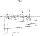
- a machine body inclination angle sensor 33 that senses an inclination angle ⁇ (see FIG. 5 ) of the upper swing structure 12 (the machine body 1B) relative to a reference plane (for example, a horizontal plane) is attached to the upper swing structure 12.
- angle sensors 30, 31 and 32 in the present embodiment are rotary potentiometers, they can each be replaced by an inclination angle sensor relative to a reference plane (for example, a horizontal plane) or an inertial measurement unit (IMU) or the like.
- a reference plane for example, a horizontal plane
- IMU inertial measurement unit
- an operation device 47a ( FIG. 2 ) that has a traveling right lever 23a ( FIG. 1 ) and is for operating a traveling right hydraulic motor 3a (lower track structure 11)
- an operation device 47b ( FIG. 2 ) that has a traveling left lever 23b ( FIG. 1 ) and is for operating a traveling left hydraulic motor 3b (lower track structure 11)
- operation devices 45a and 46a ( FIG. 2 ) that share an operation right lever 1a ( FIG. 1 ) and are for operating the boom cylinder 5 (boom 8) and the bucket cylinder 7 (bucket 10)
- operation devices 45b and 46b ( FIG. 2 ) that share an operation left lever 1b ( FIG.
- the traveling right lever 23a, the traveling left lever 23b, the operation right lever 1a and the operation left lever 1b may be generically referred to as operation levers 1 and 23.
- An engine 18 as a prime mover mounted on the upper swing structure 12 drives the hydraulic pumps 2a and 2b and a pilot pump 48.
- the hydraulic pumps 2a and 2b are variable displacement pumps whose displacements are controlled by regulators 2aa and 2ba, whereas the pilot pump 48 is a fixed displacement pump.
- the hydraulic pumps 2 and the pilot pump 48 suck in a hydraulic working fluid from a tank 200.
- a shuttle block 162 is provided at an intermediate part of pilot lines 144, 145, 146, 147, 148 and 149. Hydraulic signals outputted from the operation devices 45, 46 and 47 are inputted also to the regulators 2aa and 2ba through the shuttle block 162. While detailed configuration of the shuttle block 162 is omitted, the hydraulic signals are inputted to the regulators 2aa and 2ba through the shuttle block 162, and the delivery flow rates of the hydraulic pumps 2a and 2b are controlled according to the hydraulic signals.
- the lock valve 39 in this example is a solenoid switching valve, and a solenoid driving section thereof is electrically connected to a position sensor for a gate lock lever (not illustrated) disposed in the cabin ( FIG. 1 ). The position of the gate lock lever is sensed by the position sensor, and a signal according to the position of the gate lock lever is inputted from the position sensor to the lock valve 39.
- the operation devices 45, 46 and 47 are operation devices of a hydraulic pilot system, and, based on the hydraulic working fluid delivered from the pilot pump 48, generate pilot pressures (also called operation pressures) according to the operation amounts (for example, lever strokes) and operating directions of the operation levers 1, 23 operated by the operator.
- the thus generated pilot pressures are supplied to hydraulic driving sections 150a to 155b of corresponding flow control valves 15a to 15f ( FIG. 2 or 3 ) through pilot lines 144a to 149b (see FIG. 3 ), and are utilized as control signals for driving these flow control valves 15a to 15f.
- the hydraulic working fluid delivered from the hydraulic pump 2 is supplied to the traveling right hydraulic motor 3a, the traveling left hydraulic motor 3b, the swing hydraulic motor 4, the boom cylinder 5, the arm cylinder 6 and the bucket cylinder 7 through the flow control valves 15a, 15b, 15c, 15d, 15e and 15f (see FIG. 2 ).
- the boom cylinder 5 and the arm cylinder 6 and the bucket cylinder 7 are extended or contracted, whereby the boom 8, the arm 9 and the bucket 10 are each rotated, and the position and posture of the bucket 10 are changed.
- the swing hydraulic motor 4 is rotated, whereby the upper swing structure 12 is swung relative to the lower track structure 11.
- the traveling right hydraulic motor 3a and the traveling left hydraulic motor 3b are rotated, to cause the lower track structure 11 to travel.
- the flow control valves 15a, 15b, 15c, 15d, 15e and 15f are flow control valves of an open center bypass system, and when spools are located in neutral positions, the hydraulic working fluid entirely flows through center bypass lines to the tank 200.
- a center bypass line bleed-off opening
- a line communicating with the actuators a meter-in opening and a meter-out opening
- FIG. 2 depicts the actual system in a simplified form, there are the flow control valves 15 whose bleed-off lines are not connected to the tank 200 on an illustration basis, but, in practice, all of the flow control valves 15 are flow control valves 15 of the open center bypass system.
- the tank 200 is provided with a hydraulic working fluid temperature sensor 210 for sensing the temperature of the hydraulic working fluid for driving the hydraulic actuators.
- the hydraulic working fluid temperature sensor 210 can also be disposed outside of the tank 200, and, for example, may be attached to an inlet line or an outlet line for the tank 200.
- FIG. 4 is a configuration diagram of a machine control (MC) system possessed by the hydraulic excavator according to the present embodiment.
- the system of FIG. 4 as MC, performs a processing of controlling the velocity of each of the hydraulic cylinders 5, 6 and 7 and the front work device 1A based on a predetermined condition when the operation devices 45 and 46 are operated by the operator.
- the machine control (MC) may be referred to as "semi-automatic control" of controlling the operation of the operation device 1A by a computer only when the operating devices 45 and 46 are operated, in contrast to “automatic control” of controlling the operation of the work device 1A by a computer when the operation devices 45 and 46 are not operated.
- the details of the MC in the present embodiment will be described below.
- a control signal for example, for extending the boom cylinder 5 to forcibly performing a boom raising operation
- a control signal for forcibly operating at least one of the hydraulic actuators 5, 6 and 7 such that the position of a tip of the work device 1A is held on a target surface 60 and a region on an upper side thereof is outputted to the corresponding one of the flow control valves 15a, 15b and 15c, based on the relation between the target surface 60 (see FIG. 5 ) and the position of the tip of the work device 1A (in the present embodiment, the claw tip of the bucket 10) .
- the MC prevents the claw tip of the bucket 10 from penetrating to the lower side of the target surface 60, excavation along the target surface 60 can be performed irrespectively of the degree of the operator's skill.
- a control point of the front work device 1A at the time of the MC is set at the claw tip of the bucket 10 of the hydraulic excavator (the tip of the work device 1A) in the present embodiment
- the control point can be changed to other point than the bucket claw tip insofar as it is a point at the tip portion of the operation device 1A.
- a bottom surface of the bucket 10 or an outermost portion of the bucket link 13 can also be selected.
- the system of FIG. 4 includes a work device posture sensor 50, a target surface setting device 51, an operator operation amount sensor 52a, a display device (for example, liquid crystal display) 53 which is disposed in the cabin and is capable of displaying the positional relation between the target surface 600 and the work device 1A, and a controller (controller) 40 which administers MC control.
- a work device posture sensor 50 a target surface setting device 51
- an operator operation amount sensor 52a for example, a display device 53 which is disposed in the cabin and is capable of displaying the positional relation between the target surface 600 and the work device 1A
- a controller (controller) 40 which administers MC control.
- the work device posture sensor (posture sensor) 50 includes a boom angle sensor 30, an arm angle sensor 31, a bucket angle sensor 32, and a machine body inclination angle sensor 33. These angle sensors 30, 31, 32 and 33 function as posture sensors for sensing physical quantities concerning the postures of the boom 8, the arm 9 and the bucket 10 which are the plurality of front members.
- the target surface setting device 51 is an interface capable of inputting information concerning the target surface 60 (inclusive of position information and inclination angle information concerning each target surface).
- the target surface setting device 51 is connected to an external terminal (not illustrated) in which three-dimensional data of the target surface defined on a global coordinate system (absolute coordinate system) is stored. Note that inputting of the target surface through the target surface setting device 51 may be manually performed by the operator.
- the operator operation amount sensor (operation amount sensor) 52a includes pressure sensors 70a, 70b, 71a, 71b, 72a and 72b that acquire operation pressures (first control signals) generated in pilot lines 144, 145 and 146 by the operator's operation of the operation levers 1a and 1b (operation devices 45a, 45b and 46a).
- These pressure sensors 70a, 70b, 71a, 71b, 72a and 72b function as operation amount sensors that sense physical quantities concerning the operator's operation amounts of the boom 7 (boom cylinder 5), the arm 8 (arm cylinder 6) and the bucket 9 (bucket cylinder 7) through the operation devices 45a, 45b and 46a.
- the front control hydraulic unit 160 includes: pressure sensors 70a and 70b that are provided in pilot lines 144a and 144b of the operation device 45a for the boom 8 and that sense a pilot pressure (first control signal) as an operation amount of the operation lever 1a; a solenoid proportional valve 54a that is connected on primary port side thereof to the pilot pump 48 through a pump line 148a and outputs a pilot pressure from the pilot pump 48 with pressure reduction; a shuttle valve 82a that is connected to the pilot line 144a of the operation device 45a for the boom 8 and a secondary port side of the solenoid proportional valve 54a, that selects the high pressure side one of a pilot pressure in the pilot line 144a and a control pressure (second control signal) outputted from the solenoid proportional valve 54a, and that guides the selected pressure to the hydraulic driving section 150a of the flow control valve 15a; and a solenoid proportional valve 54b that is disposed in the pilot line 144b of the operation device 45a for the boom
- the front control hydraulic unit 160 is provided with: pressure sensors 71a and 71b that are disposed in the pilot lines 145a and 145b for the arm 9, that sense a pilot pressure (first control signal) as an operation amount of the operation lever 1b, and that output the pilot pressure to the controller 40; a solenoid proportional valve 55b that is disposed in the pilot line 145b and reduces and outputs the pilot pressure (first control signal) based on a control signal from the controller 40; and a solenoid proportional valve 55a that is disposed in the pilot line 145a and reduces and outputs the pilot pressure (first control signal) based on a control signal from the controller 40.
- the front control hydraulic unit 160 is provided in pilot lines 146a and 146b for the bucket 10 with: pressure sensors 72a and 72b that sense the pilot pressure (first control signal) as the operation amount of the operation lever 1a and output the pilot pressure to the controller 40; solenoid proportional valves 56a and 56b that reduce and output the pilot pressure (first control signal) based on a control signal from the controller 40; solenoid proportional valves 56c and 56d that are connected on a primary port side thereof to the pilot pump 48 and reduce and output a pilot pressure from the pilot pump 48; and shuttle valves 83a and 83b that select a high pressure side one of the pilot pressure in the pilot lines 146a and 146b and a control pressure outputted from the solenoid proportional valves 56c and 56d and guide the selected pressure to the hydraulic driving sections 152a and 152b of the flow control valve 15c.
- connection wires for the pressure sensors 70, 71 and 72 and the controller 40 are omitted for want of space.
- the solenoid proportional valves 54b, 55a, 55b, 56a and 56b have their openings at maximum when not energized, and the openings are reduced as a current as a control signal from the controller 40 is increased.
- the solenoid proportional valves 54a, 56c and 56d have their openings at zero when not energized, have their openings when energized, and the openings are enlarged as the current (control signal) from the controller 40 is increased. In this way, the openings of the solenoid proportional valves 54, 55 and 56 are ones according to the control signal from the controller 40.
- control hydraulic unit 160 configured as above, when the control signals are outputted from the controller 40 to drive the solenoid proportional valves 54a, 56c and 56d, a pilot pressure (second control signal) can be generated even in the case where operator's operation of the corresponding operation devices 45a and 46a is absent; therefore, a boom raising operation, a bucket crowding operation and a bucket dumping operation can be forcibly generated.
- a pilot pressure (second control signal) obtained by reducing the pilot pressure (first control signal) generated by the operator's operation of the operation devices 45a, 45b and 46a can be generated; therefore, the velocities of a boom lowering operation, an arm crowding/dumping operation and a bucket crowding/dumping operation can be forcibly reduced from the values according to the operator's operation.
- the pilot pressure generated by operation of the operating devices 45a, 45b and 46a is referred to as the "first control signal.”
- a pilot pressure generated by driving the solenoid proportional valves 54b, 55a, 55b, 56a and 56b by the controller 40 and correcting (reducing) the first control signal and a pilot pressure newly generated separately from the first control signal by driving the solenoid proportional valves 54a, 56c and 56d by the controller 40 are referred to as the "second control signals.”
- the second control signals are generated when the velocity vector of the control point of the operation device 1A generated by the first control signal is contrary to a predetermined condition, and is generated as a control signal for generating a velocity vector of a control point of the operation device 1A suitable for the predetermined condition.
- the second control signal is preferentially made to act on the hydraulic driving section, the first control signal is interrupted by the solenoid proportional valve, and the second control signal is inputted to the hydraulic driving section on the other side.
- the flow control valves 15a to 15c those for which the second control signal has been calculated are controlled based on the second control signal, whereas those for which the second control signal has not been calculated are controlled based on the first control signal, and those for which both the first and second control signals have not been generated are not controlled (driven).
- the MC can also be said to be a control of the flow control valves 15a to 15c based on the second control signal.
- the controller 40 includes an input section 91, a central processing unit (CPU) 92 as a processor, a read only memory (ROM) 93 and a random access memory (RAM) 94 as storage devices, and an output section 95.
- the input section 91 receives as inputs a signal from the angle sensors 30 to 32 and the inclination angle sensor 33 as the work device posture sensor 50, a signal from the target surface setting device 51 as a device for setting the target surface 600, and a signal from the operator operation amount sensor 52a as pressure sensors (inclusive of pressure sensors 70, 71 and 72) for sensing the operation amounts from the operation devices 45a, 45b and 46a, and converts the signals into a form which can be calculated by the CPU 92.
- CPU central processing unit
- ROM read only memory
- RAM random access memory
- the ROM 93 is a recording medium in which are stored a control program for executing the MC inclusive of a processes according to a flow chart to be described later, and various information necessary for execution of the flow chart.
- the CPU 92 performs a predetermined calculation process on the signals taken in from the input section 91 and the memories 93 and 94 according to the control program stored in the ROM 93.
- the output section 95 generates output signals according to the results of calculation in the CPU 92, and outputs the signals to the solenoid proportional valves 54 to 56 or the display device 53, to thereby drive and/or control the hydraulic actuators 5 to 7 or display images of the machine body 1B, the bucket 10 and the target surface 60 and the like on a screen of the display device 53.
- controller 40 in FIG. 4 includes semiconductor memories of the ROM 93 and the RAM 94 as storage devices, they can be particularly replaced by other storage devices; for example, a magnetic storage device such as a hard disk drive may be provided.
- FIG. 6 is a functional block diagram of the controller 40.
- the controller 40 includes an MC control section 43, a solenoid proportional valve control section 44, and a display control section 374.
- the display control section 374 is a section that controls the display device 53 based on a work device posture and a target surface outputted from the MC control section 43.
- the display control section 374 includes a display ROM storing therein a multiplicity of display-related data including an image of the work device 1A and icons, and the display control section 374 reads a predetermined program based on a flag contained in input information, and controls display on the display device 53.
- FIG. 7 is a functional block diagram of the MC control section 43 in FIG. 6 .
- the MC control section 43 includes an operation amount calculation section 43a, a posture calculation section 43b, a target surface calculation section 43c, an arm cylinder velocity calculation section 49, and an actuator control section 81 (a boom control section 81a and a bucket control section 81b) .
- the operation amount calculation section 43a calculates operation amounts of the operation devices 45a, 45b and 46a (operation levers 1a and 1b) based on sensed values from the operator operation amount sensor 52a. In other words, the operation amounts of the operation devices 45a, 45b and 46a can be calculated from the sensed values from the pressure sensors 70, 71 and 72.
- operation amounts of the operation levers of the operation devices 45a, 45b and 46a may be sensed by position sensors (for example, rotary encoders) that sense rotational displacements of the operation levers.
- the posture calculation section 43b calculates the postures of the boom 8, the arm 9 and the bucket 10, the posture of the front work device 1A and the position of the claw tip of the bucket 10 in a local coordinate system, based on sensed values from the work device posture sensor 50. In addition, the posture calculation section 43b calculates an angle (that may be referred to as "arm horizontal angle ⁇ " (see FIG. 5 )) formed between a horizontal plane passing through the arm rotational center (arm pin) and the arm 9.
- the postures of the boom 8, the arm 9 and the bucket 10 and the posture of the front work device 1A can be defined on an excavator coordinate system (local coordinate system) of FIG. 5 .
- the excavator coordinate system (XZ coordinate system) of FIG. 5 is a coordinate system set on the upper swing structure 12, in which a base bottom portion of the boom 8 rotatably supported on the upper swing structure 12 is set as an origin, a Z axis is set in the vertical direction of the upper swing structure 12, and an X axis is set in a horizontal direction of the upper swing structure 12.
- the inclination angle of the boom 8 relative to the X axis is boom angle ⁇
- the inclination angle of the arm 9 relative to the boom 8 is arm angle ⁇
- the inclination angle of the bucket claw tip relative to the arm 9 is bucket angle ⁇ .
- the inclination angle of the machine body 1B (upper swing structure 12) relative to a horizontal plane (reference plane) is inclination angle ⁇ .
- the boom angle ⁇ is sensed by a boom angle sensor 30, the arm angle ⁇ by an arm angle sensor 31, the bucket angle ⁇ by a bucket angle sensor 32, and the inclination angle ⁇ is sensed by a machine body inclination angle sensor 33.
- the lengths of the boom 8, the arm 9 and the bucket 10 be L1, L2 and L3 respectively as prescribed in FIG. 5
- the coordinates of the bucket claw tip and the postures of the boom 8, the arm 9 and the bucket 10 and the posture of the work device 1A in the excavator coordinate system can be represented by L1, L2, L3, ⁇ ,
- the arm horizontal angle ⁇ that is the angle formed between the horizontal plane passing through the arm rotational center (arm pin) and the arm 9 can be calculated, for example, from the inclination angle ⁇ , the boom angle ⁇ and the arm angle ⁇ .
- a U axis is set on the horizontal plane passing through the arm rotational center (arm pin) in a global coordinate system as depicted in FIG. 5 , and the angle formed between a straight line (a straight line having a length of L2) connecting the arm rotational center and the bucket rotational center and the U axis is ⁇ .
- a counterclockwise angle is a positive angle
- a clockwise angle is a negative angle.
- the angle ⁇ in FIG. 5 is positive.
- the arm horizontal angle ⁇ can also be sensed by attaching an inclination sensor or an inertial measurement unit (IMU) or the like relative to a reference plane (for example, a horizontal plane) to the arm 9.
- IMU inertial measurement unit
- the target surface calculation section 43c calculates position information concerning the target surface 60 based on information from the target surface setting device 51, and stores the position information in the ROM 93.
- a sectional shape obtained upon cutting a three-dimensional target surface by a plane of movement of the work device 1A (an operating plane of the work implement) is utilized as the target surface 60 (a two-dimensional target surface).
- the target surface the closest to the work device 1A may be set as a target surface, or the target surface located on a lower side of the bucket claw tip may be set as a target surface, or an arbitrarily selected one of the target surfaces may be set as a target surface.
- the arm cylinder velocity calculation section 49 is a section that calculates a velocity (arm cylinder velocity) utilized as a velocity of the arm cylinder 6 when the actuator control section 81 executes the MC, and that outputs the calculation result to the actuator control section 81.
- FIG. 8 is a functional block diagram of the arm cylinder velocity calculation section 49.
- the arm cylinder velocity calculation section 49 includes a first velocity calculation section 49a, a second velocity calculation section 49b, a third velocity calculation section 49c, and a velocity selection section 49d.
- the first velocity calculation section 49a is a section that calculates a velocity (Vamt1) of the arm cylinder 6 from a sensed value of operation amount for the arm 9, of sensed values from the operator operation amount sensor 52a.
- the velocity (Vamt1) of the arm cylinder 6 calculated by the first velocity calculation section 49a may be referred to as "first velocity” or "first arm cylinder velocity.”
- the operation amount calculation section 43a calculates an arm operation amount from a sensed value of the arm operation amount by the operator operation amount sensor 52a.
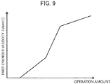
- the first velocity calculation section 49a calculates the velocity (Vamt1) of the arm cylinder 6, based on the arm operation amount calculated by the operation amount calculation section 43a and a table of FIG.
- the correlation between arm operation amount and arm cylinder velocity is prescribed on a one-to-one basis.
- the correlation between operation amount and velocity is prescribed in such a manner that the arm cylinder velocity monotonously increases with an increased in the arm operation amount, based on the cylinder velocity relative to the operation amount preliminarily determined empirically or by simulation.
- the first arm cylinder velocity calculated by the first calculation section 49a is outputted to the velocity selection section 49d.
- the second velocity calculation section 49b is a section that calculates a velocity (which may be referred to as second velocity or second arm cylinder velocity) lower than the first arm cylinder (Vamt1), calculated by the first velocity calculation section 49a, as a velocity (Vamt2) of the arm cylinder 6, taking into account the weight of an object to be driven by the arm cylinder 6 (the arm 9 and an assembly of various members located on the bucket 10 side of the arm 9, inclusive of the bucket 10 and the bucket cylinder 7).
- a velocity which may be referred to as second velocity or second arm cylinder velocity
- the second arm cylinder velocity (Vamt2) in the present embodiment is defined as a value obtained by subtracting a predetermined correction value prescribed by the arm operation amount and the arm horizontal angle ⁇ from the first arm cylinder velocity (Vamt1), assuming a situation in which the direction of a load exerted on the arm cylinder 6 by the weight of the object to be driven by the arm cylinder 6 is opposite to the driving direction of the arm cylinder, namely, a situation in which the actual velocity of the arm cylinder 6 is decelerated as compared to the first velocity (Vamt1) due to the weight of the object to be driven.
- the predetermined correction value (namely, the magnitude of the difference between the first velocity and the second velocity) is preferably set to be equal to or less than a maximum value of the velocity value to which the first velocity can be reduced due to the influence of the weight of the object to be driven.
- the second arm cylinder velocity (Vamt2) calculated by the second velocity calculation section 49b is outputted to the velocity selection section 49d.
- the third velocity calculation section 49c is a section that calculates a velocity (which may be referred to as third velocity or third arm cylinder velocity) higher than the first arm cylinder velocity (Vamt1), calculated by the first velocity calculation section 49a, as a velocity (Vamt3) of the arm cylinder 6, taking into account the weight of the target to be driven by the arm cylinder 6.
- the third arm cylinder velocity (Vamt3) in the present embodiment is defined as a value obtained by adding a predetermined correction value prescribed by the arm operation amount and the arm horizontal angle ⁇ to the first arm cylinder velocity (Vamt1), assuming a situation in which the direction of a load exerted on the arm cylinder 6 by the weight of the object to be driven by the arm cylinder 6 is the same as the driving direction of the arm cylinder, namely, a situation in which the velocity of the arm cylinder 6 is accelerated as compared to the first velocity (Vamt1) due to the weight of the object to be driven.
- the predetermined correction value (namely, the magnitude of the difference between the first velocity and the third velocity) is preferably set to be equal to or less than a maximum value of a velocity value to which the first velocity can be accelerated due to the influence of the weight of the object to be driven.
- the third arm cylinder velocity (Vamt3) calculated by the third velocity calculation section 49c is outputted to the velocity selection section 49d.
- the velocity selection section 49d is a section that determines the direction of a load exerted on the arm cylinder 6 by the weight of the object to be driven by the arm cylinder 6 inclusive of the arm 9 (the direction may be referred to as "load direction of the object to be driven”) based on a sensed value (specifically, the arm horizontal angle ⁇ ) from the posture sensor 43b, and selects one of the first velocity (Vamt1), the second velocity (Vamt2) and the third velocity (Vamt3) as an arm cylinder velocity Vam to be outputted to the actuator control section 81.
- the velocity selection section 49d can output the second velocity (Vamt2) to the actuator control section 81 when it determines that the load direction of the object to be driven is opposite to the driving direction of the arm cylinder 6, and can output the third velocity (Vamt3) to the actuator control section 81 when it determines that the load direction of the object to be driven is the same as the driving direction of the arm cylinder 6.
- the boom control section 81a and the bucket control section 81b constitute the actuator control section 81 that controls at least one of a plurality of hydraulic actuators 5, 6 and 7 according to a predetermined condition when the operation devices 45a, 45b and 46a are operated.
- the actuator control section 81 calculates target pilot pressures for the flow control valves 15a, 15b and 15c of the hydraulic cylinders 5, 6 and 7, and outputs the thus calculated target pilot pressures to the solenoid proportional valve control section 44.
- the boom control section 81a is a section that executes the MC for controlling the operation of the boom cylinder 5 (boom 8) in such a manner that the claw tip (control point) of the bucket 10 is located on or on an upper side of the target surface 60, based on the position of the target surface 60, the posture of the front work device 1A, the position of the claw tip of the bucket 10, and the velocities of the hydraulic cylinders 5, 6 and 7 when the operation devices 45a, 45b and 46a are operated.
- the boom control section 81a calculates a target pilot pressure for the flow control valve 15a of the boom cylinder 5. The details of the MC by the boom control section 81a will be described later using FIG. 13 .
- the bucket control section 81b is a section for carrying out a bucket angle control by MC when the operation devices 45a, 45b and 46a are operated. Specifically, when the distance between the target surface 60 and the claw tip of the bucket 10 is equal to or less than a predetermined value, MC (bucket angle control) for controlling the operation of the bucket cylinder 7 (bucket 10) in such a manner that the angle ⁇ of the bucket 10 relative to the target surface 60 becomes a preset bucket angle ⁇ TGT relative to the target surface.
- the bucket control section 81b calculates a target pilot pressure for the flow control valve 15c of the bucket cylinder 7.
- the solenoid proportional valve control section 44 calculates commands for the solenoid proportional valves 54 to 56, based on target pilot pressures for the flow control valves 15a, 15b and 15c outputted from the actuator control section 81. Note that in the case where the pilot pressure (first control signal) based on an operator's operation and the target pilot pressure calculated by the actuator control section 81 coincide with each other, the current value (command value) to the relevant solenoid proportional valve 54 to 56 is zero, and an operation of the relevant solenoid proportional valve 54 to 56 is not performed.
- FIG. 10 depicts a flow chart of calculation of the velocity Vam of the arm cylinder 6 that the arm cylinder velocity calculation section 49 outputs to the actuator control section 81.
- the arm cylinder velocity calculation section 49 executes the flow of FIG. 10 repeatedly at a predetermined control period. Note that in the flow described below, the velocities (Vamt1, Vamt2 and Vamt3) as objects to be outputted are calculated after the selection of the velocity by the velocity selection section 49d is performed.
- the flow is configured such that the arm cylinder velocities (Vamt1, Vamt2 and Vamt3) may be preliminarily calculated respectively by the first velocity calculation section 49a, the second velocity calculation section 49b and the third velocity calculation section 49c before selection of the velocity by the velocity selection section 49d, and, after completion of the determining process by the velocity selection section 49d, only the arm cylinder velocity according to the determination result may be outputted to the actuator control section 81.
- the velocity selection section 49d acquires an arm horizontal angle ⁇ (see FIG. 5 ) from the posture calculation section 43b.
- the velocity selection section 49d determines whether or not the arm angle ⁇ acquired in S600 is equal to or more than -90 degrees and equal to or less than 90 degrees.
- the velocity selection section 49d determines to output the third velocity (Vamt3) as the arm cylinder velocity Vam to the actuator control section 81, and the control proceeds to S620.
- the third velocity calculation section 49c calculates a correction gain k concerning the arm cylinder velocity Vamt3 based on an arm operation amount amlever calculated by the operation amount calculation section 43a.
- a function kmo for calculation of the correction gain k by the third velocity calculation section in S620 is made to be a function correlated with a meter-out opening area of an arm spool, considering that the influence of the weight of the object to be driven by the arm cylinder 6 is derived from the meter-out opening area of the arm spool concerning the flow control valve 15b.
- the third velocity calculation section 49c calculates the correction gain k based on the arm operation amount (amlever) calculated by the operation amount calculation section 43a and a table in FIG. 11 in which the correlation between the arm operation amount (amlever) and the correction gain k (function kmo) is prescribed on a one-to-one basis.
- the correlation between the operation amount and the correction gain k is prescribed in such a manner that the correction gain k increases monotonously with an increase in the arm operation amount, based on the cylinder velocity relative to the operation amount preliminarily obtained empirically or by simulation.
- the third velocity calculation section 49c calculates a correction amount (k ⁇ cos ⁇ ) concerning the arm cylinder velocity Vamt3 by use of the correction gain k obtained in S620.
- the third velocity calculation section 49c causes an estimated velocity (third velocity (Vamt3)) of the arm cylinder 6 to be a value obtained by adding the correction amount k ⁇ cos ⁇ to the first velocity Vamt1 obtained by the first velocity calculation section 49a.
- cos ⁇ is equal to or more than 0
- the correction amount k ⁇ cos ⁇ is also a value equal to or more than 0.
- the third velocity Vamt3 has a value equal to or more than the first velocity Vamt1.
- the arm cylinder velocity calculation section 49 outputs the third velocity Vamt3 as the arm cylinder velocity Vam to the actuator control section 81, and the arm cylinder velocity calculation section 49 stands by until the next control period.
- the velocity selection section 49d determines in S630 whether or not the arm operation amount amlever is smaller than a predetermined threshold levert.
- the threshold levert is an arm operation amount corresponding to a stroke amount SX at which a bleed-off opening of the arm spool closes (namely, the bleed-off opening area (center bypass opening area) becomes zero).
- the velocity selection section 49d determines that the direction of a load exerted on the arm cylinder 6 by the weight of the object to be driven is opposite to the driving direction of the arm cylinder 6, and determines to output the second velocity (Vamt2) as the arm cylinder velocity Vam to the actuator control section 81, and the control proceeds to S640.
- the second velocity calculation section 49b calculates a correction gain k concerning the arm cylinder velocity Vamt2 based on the arm operation amount amlever calculated by the operation amount calculation section 43a.
- a function kmi for calculating the correction gain k by the second velocity calculation section 49b in S640 is made to be a function correlated with a meter-in opening area and a bleed-off opening area of an arm spool, considering that the influence of the weight of the object to be driven by the arm cylinder 6 is derived from the meter-in opening area and the bleed-off opening area of the arm spool related to the flow control valve 15b.
- the second velocity calculation section 49b calculates the correction gain k based on the arm operation amount (amlever) calculated by the operation amount calculation section 43a and a table in FIG. 12 in which the correlation between arm operation amount (amlever) and the correction gain k (function kmi) is prescribed on a one-to-one basis.
- the table in FIG. 12 in which the correlation between arm operation amount (amlever) and the correction gain k (function kmi) is prescribed on a one-to-one basis.
- the correlation between the operation amount and the correction gain k is prescribed in such a manner that the correction gain k decreases monotonously with an increase in the arm operation amount, based on the cylinder velocity relative to the operation amount preliminarily obtained empirically or by simulation.
- the second velocity calculation section 49b calculates a correction amount (k ⁇ cos ⁇ ) concerning the arm cylinder velocity Vamt2 by use of the correction gain k obtained in S640.
- the second velocity calculation section 49b causes an estimated velocity (second velocity (Vamt2)) of the arm cylinder 6 to be a value obtained by adding the correction amount k ⁇ cos ⁇ to the first velocity Vamt1 obtained by the first velocity calculation section 49a.
- second velocity Vamt2 is a value smaller than the first velocity Vamt1.
- the arm cylinder velocity calculation section 49 outputs the second velocity Vam2 as the arm cylinder velocity Vam to the actuator control section 81, and the arm cylinder velocity calculation section 49 stands by until the next control period.
- the hydraulic fluid supplied from the pump 2b to the flow control valve 15b entirely flows to the arm cylinder 6 since the bleed-off opening of the arm spool concerning the flow control valve 15b is in a closed state.
- the arm cylinder velocity in this instance is determined by the flow rate of the hydraulic fluid supplied, and, therefore, there is little influence of the weight of the object to be driven by the arm cylinder 6 on the arm cylinder velocity.
- the velocity selection section 49d determines to output the first velocity (Vamt1) as the arm cylinder velocity Vam to the actuator control section 81, and the control proceeds to S650.
- the first velocity calculation section 49a deems that there is substantially no influence of the weight of the object to be driven by the arm cylinder 6 on the arm cylinder velocity, and causes the correction gain k to be zero.
- the first velocity calculation section 49a causes a velocity determined from the correlation in FIG. 9 and the arm operation amount (amlever) to be the first velocity Vamt1.
- the arm cylinder velocity calculation section 49 outputs the first velocity Vamt1 as the arm cylinder velocity Vam to the actuator control section 81, and the arm cylinder velocity calculation section 49 stands by until the next control period.
- the controller 40 in the present embodiment executes boom raising control by the boom control section 81a as MC.
- the flow of the boom raising control by the boom control section 81a is depicted in FIG. 13.
- FIG. 13 is a flow chart of the MC executed by the boom control section 81a, and the process is started when the operation devices 45a, 45b and 46a are operated by the operator.
- the boom control section 81a acquires the velocities of the hydraulic cylinders 5, 6 and 7.
- the velocities of the boom cylinder 5 and the bucket cylinder 7 are acquired by calculation based on the operation amounts of the boom 8 and the bucket 10 calculated by the operation amount calculation section 43a.
- the cylinder velocities relative to the operation amount preliminarily obtained empirically or by simulation are set as a table similarly to FIG. 9 described above, and, according to the table, the velocities of the boom cylinder 5 and the bucket cylinder 7 are calculated.
- a velocity Vam that the arm cylinder velocity calculation section 49 outputs based on the flow of FIG. 10 described above namely, one of the first velocity Vamt1, the second velocity Vamt2 and the third velocity Vamt3 is acquired as the velocity of the arm cylinder 6.
- the boom control section 81a calculates a velocity vector of the bucket tip (claw tip) by an operator's operation, based on operating velocities of the hydraulic cylinders 5, 6 and 7 acquired in S410 and the posture of the work device 1A calculated by the posture calculation section 43b.
- the boom control section 81a calculates the distance D (see FIG. 5 ) from the bucket tip to the target surface 60 as an object to be controlled, from the position (coordinates) of the claw tip of the bucket 10 calculated by the posture calculation section 43b and the rectilinear distance including the target surface 60 stored in the ROM 93. Then, based on the distance D and the graph in FIG. 14 , a limit value ay on a lower limit side of a component perpendicular to the target surface 60 of the velocity vector of the bucket tip is calculated.
- the boom control section 81a acquires the component by perpendicular to the target surface 60, of the velocity vector B of the bucket tip by an operator's operation calculated in S420.
- the boom control section 81a determines whether or not the limit value ay calculated in S430 is equal to or more than zero.
- xy coordinates are set as depicted in the right upper part of FIG. 13 .
- an x axis is parallel to the target surface 60, and the rightward direction in the figure is positive, whereas a y axis is perpendicular to the target surface 60, and the upward direction in the figure is positive.
- the vertical component by and the limit value ay are negative, whereas the horizontal component bx, the horizontal component cx and the vertical component cy are positive.
- a case where the limit value ay is zero is a case where the distance D is zero, namely, where the claw tip is located on the target surface 60
- a case where the limit value ay is positive is a case where the distance D is negative, namely, where the claw tip is located below the target surface 60
- a case where the limit value ay is negative is a case where the distance D is positive, namely, where the claw tip is located on an upper side of the target surface 60.
- the control proceeds to S460, and in the case where the limit value ay is less than zero, the control proceeds to S480.
- the boom control section 81a determines whether or not the vertical component by of the velocity vector B of the claw tip by an operator's operation is equal to or more than zero. In the case where by is positive, it indicates that the vertical component by of the velocity vector B is upward, and in the case where by is negative, it indicates that the vertical component by of the velocity vector B is downward. In the case where the vertical component by is determined to be equal to or more than zero in S460 (namely, in the case where the vertical component by is upward), the control proceeds to S470, and in the case where the vertical component by is less than zero, the control proceeds to S500.
- the boom control section 81a compares the absolute values of the limit value ay and the vertical component by, and, in the case where the absolute value of the limit value ay is equal to or more than the absolute value of the vertical component by, the control proceeds to S500. On the other hand, in the case where the absolute value of the limit value ay is less than the absolute value of the vertical component by, the control proceeds to S530.
- a target velocity vector T is calculated.
- the vertical component ty of the target velocity vector in the case of reaching S520 is limited by the limit value ay, and forced boom raising by machine control is triggered.
- the boom control section 81a determines whether or not the vertical component by of the velocity vector B of the claw tip by an operator's operation is equal to or more than zero. In the case where the vertical component by is determined to be equal to or more than zero in S480 (namely, in the case where the vertical component is upward), the control proceeds to S530, and in the case where the vertical component by is less than zero, the control proceeds to S490.
- the boom control section 81a compares the absolute values of the limit value ay and the vertical component by, and, in the case where the absolute value of the limit value ay is equal to or more than the absolute value of the vertical component by, the control proceeds to S530. On the other hand, in the case where the absolute value of the limit value ay is less than the absolute value of the vertical component by, the control proceeds to S500.
- the boom control section 81a sets the velocity vector C to zero.
- the boom control section 81a calculates target velocities for the hydraulic cylinders 5, 6 and 7 based on the target velocity vector T (ty, tx) determined in S520 or S540. Note that as is clear from the above description, when the target velocity vector T does not coincide with the velocity vector B in the case of FIG. 13 , the target velocity vector T is realized by adding the velocity vector C generated by the operation of the boom 8 by machine control to the velocity vector B.
- the boom control section 81a calculates target pilot pressures for the flow control valves 15a, 15b and 15c of the hydraulic cylinders 5, 6 and 7 based on the target velocities for the cylinders 5, 6 and 7 calculated in S550.
- the boom control section 81a outputs the target pilot pressures for the flow control valves 15a, 15b and 15c of the hydraulic cylinders 5, 6 and 7 to the solenoid proportional valve control section 44.
- the solenoid proportional valve control section 44 controls the solenoid proportional valves 54, 55 and 56 in such a manner that the target pilot pressures act on the flow control valves 15a, 15b and 15c of the hydraulic cylinders 5, 6 and 7, whereby excavation by the work device 1A is performed.
- the solenoid proportional valve 55c is controlled in such a manner that the tip of the bucket 10 does not penetrate into the target surface 60, and a raising operation of the boom 8 is automatically performed.
- boom control force boom raising control
- bucket control bucket angle control
- the operator performs a crowding operation of the arm 9.
- a command is outputted from the boom control section 81a to the solenoid valve 54a, and a control (MC) for raising the boom 8 is performed.
- the weight of the front work device (the arm 9 and the bucket 10) on the front side of the arm 9 acts in the direction for accelerating the arm cylinder velocity, and, therefore, the actual arm cylinder velocity tends to be higher than the value (first velocity Vamt1) estimated from the arm operation amount (amlever) in that instance.
- the control flow of FIG. 10 ensures that in the case where the arm horizontal angle ⁇ is equal to or less than 90 degrees, the third velocity Vamt3 higher than the first velocity Vamt1 is outputted as an arm cylinder velocity Vam to the actuator control section 81.
- the correction amount namely, the difference k ⁇ cos ⁇ between the first velocity Vamt1 and the third velocity Vamt3 is varied according to variations in the arm horizontal angle ⁇ (see FIG. 10 ) and the arm operation amount (see FIG. 11 ), and, therefore, MC stability and working accuracy can be further enhanced.
- the difference between the arm cylinder velocity Vam (Vamt2) inputted to the actuator control section 81 and utilized for MC and the actual arm cylinder velocity is smaller than that in the conventional method in which the first velocity Vamt1 is always utilized as the arm cylinder velocity for MC irrespectively of the magnitude of the arm horizontal angle ⁇ . Consequently, the boom raising operation amount by the MC can be calculated more properly, and, therefore, the MC is stabilized, and the working accuracy of the target surface 60 is enhanced.
- the correction amount namely, the difference k ⁇ cos ⁇ between the first velocity Vamt1 and the second velocity Vamt2 is varied according to variations in the arm horizontal angle ⁇ (see FIG. 10 ) and the arm operation amount (see FIG. 12 ), and, therefore, MC stability and working accuracy can be further enhanced.
- an appropriate correction amount is added to the arm cylinder velocity (first velocity Vamt1) estimated from the arm operation amount (amlever), whereby the difference from the actual arm cylinder velocity is reduced. Consequently, it becomes possible to calculate an appropriate boom raising operation amount (namely, target velocities of the hydraulic cylinders 5, 6 and 7), and it is possible to stabilize the behavior of the bucket tip in MC.
- a control of not correcting the arm cylinder velocity is performed.
- a system may be configured such that in this case, also, the second velocity is outputted to the actuator control section 81.
- a system may be configured in which the control proceeds to S640 in the case where the determination in S610 in FIG. 10 is NO.
- the posture information concerning the excavator may be calculated not by the angle sensors but by cylinder stroke sensors.
- a configuration may be adopted in which a command current generated from an electric lever is controlled.
- the velocity vector may be obtained not from the pilot pressures by operator's operations but from angular velocities calculated by differentiating the angles of the boom 8, the arm 9 and the bucket 10.
- the functions and carrying-out processes of the configurations and the like may be realized by hardware (for example, designing the logics for carrying out the functions by integrated circuit).
- the configurations concerning the controller 40 may be a program (software) which, by being executed, realizes the functions concerning the configurations of the controller 40.
- Information concerning the program can be stored, for example, in semiconductor memory (flash memory, SSD, and the like), magnetic storage device (hard disk drive, and the like), recording medium (magnetic disk, optical disk, and the like) and so on.
Landscapes
- Engineering & Computer Science (AREA)
- Mining & Mineral Resources (AREA)
- Civil Engineering (AREA)
- General Engineering & Computer Science (AREA)
- Structural Engineering (AREA)
- Mechanical Engineering (AREA)
- Physics & Mathematics (AREA)
- Fluid Mechanics (AREA)
- Life Sciences & Earth Sciences (AREA)
- General Life Sciences & Earth Sciences (AREA)
- Paleontology (AREA)
- Operation Control Of Excavators (AREA)
Claims (4)
- Machine de chantier (1) comprenant :un dispositif de travail (1A) qui a une pluralité d'éléments avant incluant un bras (9) ;une pluralité d'actionneurs hydrauliques (5, 6, 7) qui incluent un vérin de bras (6) entraînant le bras (9) et qui entraînent la pluralité d'éléments avant ;un dispositif d'actionnement (45, 46) qui donne une instruction d'actionnements de la pluralité d'actionneurs hydrauliques (5, 6, 7) en accord avec un actionnement d'un opérateur ;un contrôleur (40) ayant une section de commande d'actionneur (81) qui commande l'un au moins de la pluralité d'actionneurs hydrauliques (5, 6, 7) en accord avec des vitesses de la pluralité d'actionneurs hydrauliques (5, 6, 7) et une condition prédéterminée quand le dispositif d'actionnement (45, 46) est actionné ;un capteur de posture (50) qui détecte une quantité physique concernant une posture du bras (9) ; etun capteur de d'amplitude actionnement (52a) qui détecte une quantité physique concernant une amplitude d'actionnement pour le bras (9) parmi des amplitudes d'actionnement du dispositif de travail (45, 46),caractérisée en ce quele contrôleur (40) inclut :une première section de calcul de vitesse (49a) qui calcule une première vitesse calculée à partir d'une valeur détectée depuis le capteur d'amplitude d'actionnement (52a) à titre de vitesse du vérin de bras (6) ;une deuxième section de calcul de vitesse (49b) qui, sur la base d'une valeur détectée depuis le capteur de posture (50), détermine une direction d'une charge appliquée sur le vérin de bras (6) via le poids du bras (9), et, lorsqu'il est déterminé que la direction de la charge est opposée à une direction d'entraînement du vérin de bras (6), calcule à titre de vitesse du vérin de bras une deuxième vitesse inférieure à la première vitesse à titre de vitesse du vérin de bras (6) ; etune troisième section de calcul de vitesse (49c) qui, lorsqu'il est déterminé que la direction de la charge est la même que la direction d'entraînement du vérin de bras (6), calcule à titre de vitesse du vérin de bras (6) une troisième vitesse égale ou supérieure à la première vitesse à titre de vitesse du vérin de bras (6).
- Machine de chantier selon la revendication 1, dans laquellela deuxième section de calcul de vitesse (49b) calcule la deuxième vitesse en tenant compte d'une influence du poids du bras (9), etla troisième section de calcul de vitesse (49c) calcule la troisième vitesse en tenant compte d'une influence du poids du bras (9).
- Machine de chantier selon la revendication 1, dans laquelle
chacune d'une première correction quantitative qui est un écart entre la première vitesse et la deuxième vitesse, et d'une seconde correction quantitative qui est un écart entre la première vitesse et la troisième vitesse varie en accord avec des variations dans une valeur détectée depuis le capteur de posture (50) et une valeur détectée depuis le capteur d'amplitude d'actionnement (52 a). - Machine de chantier selon la revendication 1,comprenant une section de sélection de vitesse (49d) qui sort une vitesse parmi la première vitesse calculée par la première section de calcul de vitesse (49a), la deuxième section de calcul de vitesse calculée par la deuxième section de calcul de vitesse (49b) et la troisième section de calcul de vitesse calculée par la troisième section de calcul de vitesse (49c) vers la section de commande d'actionneur (81), dans laquellela section de sélection de vitesse (49d) :sort, quand une valeur détectée depuis le capteur d'amplitude d'actionnement (52a) est égale ou supérieure à une valeur prédéterminée, la première vitesse vers la section de commande d'actionneur (81) à titre de vitesse du vérin de bras (6) ;sort, lorsqu'il est déterminé que la valeur détectée depuis le capteur d'amplitude d'actionnement (52a) est inférieure à la valeur prédéterminée et que la direction de la charge est opposée à la direction d'entraînement du vérin de bras (6), la deuxième vitesse vers la section de commande d'actionneur (81) à titre de vitesse du vérin de bras (6) ; etsort, lorsqu'il est déterminé que la valeur détectée depuis le capteur d'amplitude actionnement (52a) est inférieure à la valeur prédéterminée et que la direction de la charge est la même que la direction d'entraînement du vérin de bras (6), la troisième vitesse vers la section de commande d'actionneur (81) à titre de vitesse du vérin de bras (6).
Applications Claiming Priority (1)
| Application Number | Priority Date | Filing Date | Title |
|---|---|---|---|
| PCT/JP2018/015917 WO2019202673A1 (fr) | 2018-04-17 | 2018-04-17 | Engin de chantier |
Publications (3)
| Publication Number | Publication Date |
|---|---|
| EP3783155A1 EP3783155A1 (fr) | 2021-02-24 |
| EP3783155A4 EP3783155A4 (fr) | 2021-12-08 |
| EP3783155B1 true EP3783155B1 (fr) | 2022-12-14 |
Family
ID=68240058
Family Applications (1)
| Application Number | Title | Priority Date | Filing Date |
|---|---|---|---|
| EP18915478.4A Active EP3783155B1 (fr) | 2018-04-17 | 2018-04-17 | Engin de chantier |
Country Status (6)
| Country | Link |
|---|---|
| US (1) | US11453995B2 (fr) |
| EP (1) | EP3783155B1 (fr) |
| JP (1) | JP6889806B2 (fr) |
| KR (1) | KR102414027B1 (fr) |
| CN (1) | CN111032970B (fr) |
| WO (1) | WO2019202673A1 (fr) |
Families Citing this family (7)
| Publication number | Priority date | Publication date | Assignee | Title |
|---|---|---|---|---|
| GB2577899B (en) * | 2018-10-09 | 2023-03-29 | Bamford Excavators Ltd | A machine, controller, and control method |
| CN114008277B (zh) * | 2019-08-08 | 2023-08-29 | 住友建机株式会社 | 挖土机 |
| JP7182726B2 (ja) * | 2019-09-30 | 2022-12-02 | 日立建機株式会社 | 作業機械 |
| JP7182579B2 (ja) * | 2020-03-27 | 2022-12-02 | 日立建機株式会社 | 作業機械 |
| JP7269301B2 (ja) | 2021-09-30 | 2023-05-08 | 日立建機株式会社 | 作業機械 |
| JP7807956B2 (ja) * | 2022-03-23 | 2026-01-28 | 日立建機株式会社 | 作業機械 |
| WO2026070244A1 (fr) * | 2024-09-27 | 2026-04-02 | 株式会社小松製作所 | Engin de chantier |
Family Cites Families (18)
| Publication number | Priority date | Publication date | Assignee | Title |
|---|---|---|---|---|
| JPS58120925A (ja) * | 1982-01-12 | 1983-07-19 | Hitachi Constr Mach Co Ltd | 油圧シヨベルの作業軌跡制御装置 |
| JP2566745B2 (ja) * | 1994-04-29 | 1996-12-25 | 三星重工業株式会社 | 電子制御油圧掘削機の自動平坦作業方法 |
| JP2007218405A (ja) * | 2006-02-20 | 2007-08-30 | Ishikawajima Constr Mach Co | 建設機械の油圧回路 |
| KR20110077061A (ko) * | 2009-12-30 | 2011-07-07 | 볼보 컨스트럭션 이큅먼트 에이비 | 오픈센터 방식의 굴삭기용 유압시스템의 선회모터 제어방법 |
| JP6023053B2 (ja) * | 2011-06-10 | 2016-11-09 | 日立建機株式会社 | 作業機械 |
| WO2013094616A1 (fr) * | 2011-12-22 | 2013-06-27 | 日立建機株式会社 | Machine de travail |
| CN105339558B (zh) * | 2014-06-04 | 2017-05-31 | 株式会社小松制作所 | 建筑机械的控制系统、建筑机械及建筑机械的控制方法 |
| CN105008623B (zh) | 2014-06-04 | 2017-07-14 | 株式会社小松制作所 | 建筑机械的控制系统、建筑机械及建筑机械的控制方法 |
| BR112016030088A2 (pt) * | 2014-06-25 | 2017-08-22 | Siemens Industry Inc | sistema para uma máquina de escavação |
| JP5865510B2 (ja) * | 2014-09-10 | 2016-02-17 | 株式会社小松製作所 | 作業車両および作業車両の制御方法 |
| JP6291394B2 (ja) * | 2014-10-02 | 2018-03-14 | 日立建機株式会社 | 作業機械の油圧駆動システム |
| JP6250515B2 (ja) | 2014-10-07 | 2017-12-20 | 日立建機株式会社 | 建設機械の油圧制御装置 |
| US9834905B2 (en) * | 2015-09-25 | 2017-12-05 | Komatsu Ltd. | Work machine control device, work machine, and work machine control method |
| JP6474718B2 (ja) * | 2015-12-25 | 2019-02-27 | 日立建機株式会社 | 建設機械の油圧制御装置 |
| JP6564739B2 (ja) * | 2016-06-30 | 2019-08-21 | 日立建機株式会社 | 作業機械 |
| JP6666209B2 (ja) * | 2016-07-06 | 2020-03-13 | 日立建機株式会社 | 作業機械 |
| JP2018044305A (ja) * | 2016-09-12 | 2018-03-22 | 日立建機株式会社 | 油圧ショベル |
| EP3683364B1 (fr) * | 2017-09-13 | 2022-08-03 | Hitachi Construction Machinery Co., Ltd. | Machine de travail |
-
2018
- 2018-04-17 JP JP2020514835A patent/JP6889806B2/ja active Active
- 2018-04-17 EP EP18915478.4A patent/EP3783155B1/fr active Active
- 2018-04-17 US US16/641,772 patent/US11453995B2/en active Active
- 2018-04-17 CN CN201880054566.9A patent/CN111032970B/zh active Active
- 2018-04-17 KR KR1020207004664A patent/KR102414027B1/ko active Active
- 2018-04-17 WO PCT/JP2018/015917 patent/WO2019202673A1/fr not_active Ceased
Also Published As
| Publication number | Publication date |
|---|---|
| JPWO2019202673A1 (ja) | 2020-09-03 |
| JP6889806B2 (ja) | 2021-06-18 |
| US20200248430A1 (en) | 2020-08-06 |
| KR102414027B1 (ko) | 2022-06-29 |
| CN111032970A (zh) | 2020-04-17 |
| KR20200032149A (ko) | 2020-03-25 |
| EP3783155A4 (fr) | 2021-12-08 |
| EP3783155A1 (fr) | 2021-02-24 |
| CN111032970B (zh) | 2022-02-25 |
| WO2019202673A1 (fr) | 2019-10-24 |
| US11453995B2 (en) | 2022-09-27 |
Similar Documents
| Publication | Publication Date | Title |
|---|---|---|
| US11053661B2 (en) | Work machine | |
| EP3783155A1 (fr) | Engin de chantier | |
| KR102189225B1 (ko) | 작업 기계 | |
| KR102024701B1 (ko) | 작업 기계 | |
| US11479941B2 (en) | Work machine | |
| US12454806B2 (en) | Work machine | |
| KR102520407B1 (ko) | 작업 기계 | |
| KR102130562B1 (ko) | 작업 기계 | |
| KR102154581B1 (ko) | 작업 기계 | |
| EP3467210A1 (fr) | Engin de travaux | |
| US12134875B2 (en) | Work machine | |
| US12084836B2 (en) | Work machine | |
| EP4317611A1 (fr) | Engin de chantier | |
| WO2020065739A1 (fr) | Machine de travail | |
| JP2026043707A (ja) | 作業機械制御装置、作業機械および作業機械制御方法 |
Legal Events
| Date | Code | Title | Description |
|---|---|---|---|
| STAA | Information on the status of an ep patent application or granted ep patent |
Free format text: STATUS: THE INTERNATIONAL PUBLICATION HAS BEEN MADE |
|
| PUAI | Public reference made under article 153(3) epc to a published international application that has entered the european phase |
Free format text: ORIGINAL CODE: 0009012 |
|
| STAA | Information on the status of an ep patent application or granted ep patent |
Free format text: STATUS: REQUEST FOR EXAMINATION WAS MADE |
|
| 17P | Request for examination filed |
Effective date: 20201117 |
|
| AK | Designated contracting states |
Kind code of ref document: A1 Designated state(s): AL AT BE BG CH CY CZ DE DK EE ES FI FR GB GR HR HU IE IS IT LI LT LU LV MC MK MT NL NO PL PT RO RS SE SI SK SM TR |
|
| AX | Request for extension of the european patent |
Extension state: BA ME |
|
| DAV | Request for validation of the european patent (deleted) | ||
| DAX | Request for extension of the european patent (deleted) | ||
| A4 | Supplementary search report drawn up and despatched |
Effective date: 20211105 |
|
| RIC1 | Information provided on ipc code assigned before grant |
Ipc: E02F 9/26 20060101ALI20211029BHEP Ipc: E02F 3/43 20060101ALI20211029BHEP Ipc: E02F 9/22 20060101AFI20211029BHEP |
|
| GRAP | Despatch of communication of intention to grant a patent |
Free format text: ORIGINAL CODE: EPIDOSNIGR1 |
|
| STAA | Information on the status of an ep patent application or granted ep patent |
Free format text: STATUS: GRANT OF PATENT IS INTENDED |
|
| INTG | Intention to grant announced |
Effective date: 20220922 |
|
| GRAS | Grant fee paid |
Free format text: ORIGINAL CODE: EPIDOSNIGR3 |
|
| GRAA | (expected) grant |
Free format text: ORIGINAL CODE: 0009210 |
|
| STAA | Information on the status of an ep patent application or granted ep patent |
Free format text: STATUS: THE PATENT HAS BEEN GRANTED |
|
| AK | Designated contracting states |
Kind code of ref document: B1 Designated state(s): AL AT BE BG CH CY CZ DE DK EE ES FI FR GB GR HR HU IE IS IT LI LT LU LV MC MK MT NL NO PL PT RO RS SE SI SK SM TR |
|
| REG | Reference to a national code |
Ref country code: GB Ref legal event code: FG4D |
|
| REG | Reference to a national code |
Ref country code: CH Ref legal event code: EP |
|
| REG | Reference to a national code |
Ref country code: DE Ref legal event code: R096 Ref document number: 602018044376 Country of ref document: DE |
|
| REG | Reference to a national code |
Ref country code: IE Ref legal event code: FG4D |
|
| REG | Reference to a national code |
Ref country code: AT Ref legal event code: REF Ref document number: 1537726 Country of ref document: AT Kind code of ref document: T Effective date: 20230115 |
|
| REG | Reference to a national code |
Ref country code: LT Ref legal event code: MG9D |
|
| REG | Reference to a national code |
Ref country code: NL Ref legal event code: MP Effective date: 20221214 |
|
| PG25 | Lapsed in a contracting state [announced via postgrant information from national office to epo] |
Ref country code: SE Free format text: LAPSE BECAUSE OF FAILURE TO SUBMIT A TRANSLATION OF THE DESCRIPTION OR TO PAY THE FEE WITHIN THE PRESCRIBED TIME-LIMIT Effective date: 20221214 Ref country code: NO Free format text: LAPSE BECAUSE OF FAILURE TO SUBMIT A TRANSLATION OF THE DESCRIPTION OR TO PAY THE FEE WITHIN THE PRESCRIBED TIME-LIMIT Effective date: 20230314 Ref country code: LT Free format text: LAPSE BECAUSE OF FAILURE TO SUBMIT A TRANSLATION OF THE DESCRIPTION OR TO PAY THE FEE WITHIN THE PRESCRIBED TIME-LIMIT Effective date: 20221214 Ref country code: FI Free format text: LAPSE BECAUSE OF FAILURE TO SUBMIT A TRANSLATION OF THE DESCRIPTION OR TO PAY THE FEE WITHIN THE PRESCRIBED TIME-LIMIT Effective date: 20221214 |
|
| REG | Reference to a national code |
Ref country code: AT Ref legal event code: MK05 Ref document number: 1537726 Country of ref document: AT Kind code of ref document: T Effective date: 20221214 |
|
| PG25 | Lapsed in a contracting state [announced via postgrant information from national office to epo] |
Ref country code: RS Free format text: LAPSE BECAUSE OF FAILURE TO SUBMIT A TRANSLATION OF THE DESCRIPTION OR TO PAY THE FEE WITHIN THE PRESCRIBED TIME-LIMIT Effective date: 20221214 Ref country code: LV Free format text: LAPSE BECAUSE OF FAILURE TO SUBMIT A TRANSLATION OF THE DESCRIPTION OR TO PAY THE FEE WITHIN THE PRESCRIBED TIME-LIMIT Effective date: 20221214 Ref country code: HR Free format text: LAPSE BECAUSE OF FAILURE TO SUBMIT A TRANSLATION OF THE DESCRIPTION OR TO PAY THE FEE WITHIN THE PRESCRIBED TIME-LIMIT Effective date: 20221214 Ref country code: GR Free format text: LAPSE BECAUSE OF FAILURE TO SUBMIT A TRANSLATION OF THE DESCRIPTION OR TO PAY THE FEE WITHIN THE PRESCRIBED TIME-LIMIT Effective date: 20230315 |
|
| PG25 | Lapsed in a contracting state [announced via postgrant information from national office to epo] |
Ref country code: NL Free format text: LAPSE BECAUSE OF FAILURE TO SUBMIT A TRANSLATION OF THE DESCRIPTION OR TO PAY THE FEE WITHIN THE PRESCRIBED TIME-LIMIT Effective date: 20221214 |
|
| PG25 | Lapsed in a contracting state [announced via postgrant information from national office to epo] |
Ref country code: SM Free format text: LAPSE BECAUSE OF FAILURE TO SUBMIT A TRANSLATION OF THE DESCRIPTION OR TO PAY THE FEE WITHIN THE PRESCRIBED TIME-LIMIT Effective date: 20221214 Ref country code: RO Free format text: LAPSE BECAUSE OF FAILURE TO SUBMIT A TRANSLATION OF THE DESCRIPTION OR TO PAY THE FEE WITHIN THE PRESCRIBED TIME-LIMIT Effective date: 20221214 Ref country code: PT Free format text: LAPSE BECAUSE OF FAILURE TO SUBMIT A TRANSLATION OF THE DESCRIPTION OR TO PAY THE FEE WITHIN THE PRESCRIBED TIME-LIMIT Effective date: 20230414 Ref country code: ES Free format text: LAPSE BECAUSE OF FAILURE TO SUBMIT A TRANSLATION OF THE DESCRIPTION OR TO PAY THE FEE WITHIN THE PRESCRIBED TIME-LIMIT Effective date: 20221214 Ref country code: EE Free format text: LAPSE BECAUSE OF FAILURE TO SUBMIT A TRANSLATION OF THE DESCRIPTION OR TO PAY THE FEE WITHIN THE PRESCRIBED TIME-LIMIT Effective date: 20221214 Ref country code: CZ Free format text: LAPSE BECAUSE OF FAILURE TO SUBMIT A TRANSLATION OF THE DESCRIPTION OR TO PAY THE FEE WITHIN THE PRESCRIBED TIME-LIMIT Effective date: 20221214 Ref country code: AT Free format text: LAPSE BECAUSE OF FAILURE TO SUBMIT A TRANSLATION OF THE DESCRIPTION OR TO PAY THE FEE WITHIN THE PRESCRIBED TIME-LIMIT Effective date: 20221214 |
|
| PG25 | Lapsed in a contracting state [announced via postgrant information from national office to epo] |
Ref country code: SK Free format text: LAPSE BECAUSE OF FAILURE TO SUBMIT A TRANSLATION OF THE DESCRIPTION OR TO PAY THE FEE WITHIN THE PRESCRIBED TIME-LIMIT Effective date: 20221214 Ref country code: PL Free format text: LAPSE BECAUSE OF FAILURE TO SUBMIT A TRANSLATION OF THE DESCRIPTION OR TO PAY THE FEE WITHIN THE PRESCRIBED TIME-LIMIT Effective date: 20221214 Ref country code: IS Free format text: LAPSE BECAUSE OF FAILURE TO SUBMIT A TRANSLATION OF THE DESCRIPTION OR TO PAY THE FEE WITHIN THE PRESCRIBED TIME-LIMIT Effective date: 20230414 Ref country code: AL Free format text: LAPSE BECAUSE OF FAILURE TO SUBMIT A TRANSLATION OF THE DESCRIPTION OR TO PAY THE FEE WITHIN THE PRESCRIBED TIME-LIMIT Effective date: 20221214 |
|
| REG | Reference to a national code |
Ref country code: DE Ref legal event code: R097 Ref document number: 602018044376 Country of ref document: DE |
|
| PLBE | No opposition filed within time limit |
Free format text: ORIGINAL CODE: 0009261 |
|
| STAA | Information on the status of an ep patent application or granted ep patent |
Free format text: STATUS: NO OPPOSITION FILED WITHIN TIME LIMIT |
|
| PG25 | Lapsed in a contracting state [announced via postgrant information from national office to epo] |
Ref country code: DK Free format text: LAPSE BECAUSE OF FAILURE TO SUBMIT A TRANSLATION OF THE DESCRIPTION OR TO PAY THE FEE WITHIN THE PRESCRIBED TIME-LIMIT Effective date: 20221214 |
|
| 26N | No opposition filed |
Effective date: 20230915 |
|
| PG25 | Lapsed in a contracting state [announced via postgrant information from national office to epo] |
Ref country code: SI Free format text: LAPSE BECAUSE OF FAILURE TO SUBMIT A TRANSLATION OF THE DESCRIPTION OR TO PAY THE FEE WITHIN THE PRESCRIBED TIME-LIMIT Effective date: 20221214 |
|
| REG | Reference to a national code |
Ref country code: CH Ref legal event code: PL |
|
| PG25 | Lapsed in a contracting state [announced via postgrant information from national office to epo] |
Ref country code: LU Free format text: LAPSE BECAUSE OF NON-PAYMENT OF DUE FEES Effective date: 20230417 |
|
| REG | Reference to a national code |
Ref country code: BE Ref legal event code: MM Effective date: 20230430 |
|
| PG25 | Lapsed in a contracting state [announced via postgrant information from national office to epo] |
Ref country code: MC Free format text: LAPSE BECAUSE OF FAILURE TO SUBMIT A TRANSLATION OF THE DESCRIPTION OR TO PAY THE FEE WITHIN THE PRESCRIBED TIME-LIMIT Effective date: 20221214 |
|
| PG25 | Lapsed in a contracting state [announced via postgrant information from national office to epo] |
Ref country code: MC Free format text: LAPSE BECAUSE OF FAILURE TO SUBMIT A TRANSLATION OF THE DESCRIPTION OR TO PAY THE FEE WITHIN THE PRESCRIBED TIME-LIMIT Effective date: 20221214 Ref country code: LI Free format text: LAPSE BECAUSE OF NON-PAYMENT OF DUE FEES Effective date: 20230430 Ref country code: FR Free format text: LAPSE BECAUSE OF NON-PAYMENT OF DUE FEES Effective date: 20230430 Ref country code: CH Free format text: LAPSE BECAUSE OF NON-PAYMENT OF DUE FEES Effective date: 20230430 |
|
| REG | Reference to a national code |
Ref country code: IE Ref legal event code: MM4A |
|
| PG25 | Lapsed in a contracting state [announced via postgrant information from national office to epo] |
Ref country code: BE Free format text: LAPSE BECAUSE OF NON-PAYMENT OF DUE FEES Effective date: 20230430 |
|
| PG25 | Lapsed in a contracting state [announced via postgrant information from national office to epo] |
Ref country code: IE Free format text: LAPSE BECAUSE OF NON-PAYMENT OF DUE FEES Effective date: 20230417 |
|
| PG25 | Lapsed in a contracting state [announced via postgrant information from national office to epo] |
Ref country code: IE Free format text: LAPSE BECAUSE OF NON-PAYMENT OF DUE FEES Effective date: 20230417 |
|
| PG25 | Lapsed in a contracting state [announced via postgrant information from national office to epo] |
Ref country code: IT Free format text: LAPSE BECAUSE OF FAILURE TO SUBMIT A TRANSLATION OF THE DESCRIPTION OR TO PAY THE FEE WITHIN THE PRESCRIBED TIME-LIMIT Effective date: 20221214 |
|
| PG25 | Lapsed in a contracting state [announced via postgrant information from national office to epo] |
Ref country code: BG Free format text: LAPSE BECAUSE OF FAILURE TO SUBMIT A TRANSLATION OF THE DESCRIPTION OR TO PAY THE FEE WITHIN THE PRESCRIBED TIME-LIMIT Effective date: 20221214 |
|
| PG25 | Lapsed in a contracting state [announced via postgrant information from national office to epo] |
Ref country code: BG Free format text: LAPSE BECAUSE OF FAILURE TO SUBMIT A TRANSLATION OF THE DESCRIPTION OR TO PAY THE FEE WITHIN THE PRESCRIBED TIME-LIMIT Effective date: 20221214 |
|
| PG25 | Lapsed in a contracting state [announced via postgrant information from national office to epo] |
Ref country code: CY Free format text: LAPSE BECAUSE OF FAILURE TO SUBMIT A TRANSLATION OF THE DESCRIPTION OR TO PAY THE FEE WITHIN THE PRESCRIBED TIME-LIMIT; INVALID AB INITIO Effective date: 20180417 |
|
| PG25 | Lapsed in a contracting state [announced via postgrant information from national office to epo] |
Ref country code: HU Free format text: LAPSE BECAUSE OF FAILURE TO SUBMIT A TRANSLATION OF THE DESCRIPTION OR TO PAY THE FEE WITHIN THE PRESCRIBED TIME-LIMIT; INVALID AB INITIO Effective date: 20180417 |
|
| PG25 | Lapsed in a contracting state [announced via postgrant information from national office to epo] |
Ref country code: TR Free format text: LAPSE BECAUSE OF FAILURE TO SUBMIT A TRANSLATION OF THE DESCRIPTION OR TO PAY THE FEE WITHIN THE PRESCRIBED TIME-LIMIT Effective date: 20221214 |
|
| PGFP | Annual fee paid to national office [announced via postgrant information from national office to epo] |
Ref country code: GB Payment date: 20260313 Year of fee payment: 9 |
|
| PGFP | Annual fee paid to national office [announced via postgrant information from national office to epo] |
Ref country code: DE Payment date: 20260305 Year of fee payment: 9 |