EP3783238B1 - Freischneider - Google Patents
Freischneider Download PDFInfo
- Publication number
- EP3783238B1 EP3783238B1 EP19203105.2A EP19203105A EP3783238B1 EP 3783238 B1 EP3783238 B1 EP 3783238B1 EP 19203105 A EP19203105 A EP 19203105A EP 3783238 B1 EP3783238 B1 EP 3783238B1
- Authority
- EP
- European Patent Office
- Prior art keywords
- holder
- bearing
- brush cutter
- peripheral surface
- shaft bearing
- Prior art date
- Legal status (The legal status is an assumption and is not a legal conclusion. Google has not performed a legal analysis and makes no representation as to the accuracy of the status listed.)
- Active
Links
Images



Classifications
-
- F—MECHANICAL ENGINEERING; LIGHTING; HEATING; WEAPONS; BLASTING
- F16—ENGINEERING ELEMENTS AND UNITS; GENERAL MEASURES FOR PRODUCING AND MAINTAINING EFFECTIVE FUNCTIONING OF MACHINES OR INSTALLATIONS; THERMAL INSULATION IN GENERAL
- F16C—SHAFTS; FLEXIBLE SHAFTS; ELEMENTS OR CRANKSHAFT MECHANISMS; ROTARY BODIES OTHER THAN GEARING ELEMENTS; BEARINGS
- F16C27/00—Elastic or yielding bearings or bearing supports, for exclusively rotary movement
- F16C27/06—Elastic or yielding bearings or bearing supports, for exclusively rotary movement by means of parts of rubber or like materials
- F16C27/066—Ball or roller bearings
-
- F—MECHANICAL ENGINEERING; LIGHTING; HEATING; WEAPONS; BLASTING
- F16—ENGINEERING ELEMENTS AND UNITS; GENERAL MEASURES FOR PRODUCING AND MAINTAINING EFFECTIVE FUNCTIONING OF MACHINES OR INSTALLATIONS; THERMAL INSULATION IN GENERAL
- F16C—SHAFTS; FLEXIBLE SHAFTS; ELEMENTS OR CRANKSHAFT MECHANISMS; ROTARY BODIES OTHER THAN GEARING ELEMENTS; BEARINGS
- F16C27/00—Elastic or yielding bearings or bearing supports, for exclusively rotary movement
- F16C27/06—Elastic or yielding bearings or bearing supports, for exclusively rotary movement by means of parts of rubber or like materials
-
- F—MECHANICAL ENGINEERING; LIGHTING; HEATING; WEAPONS; BLASTING
- F16—ENGINEERING ELEMENTS AND UNITS; GENERAL MEASURES FOR PRODUCING AND MAINTAINING EFFECTIVE FUNCTIONING OF MACHINES OR INSTALLATIONS; THERMAL INSULATION IN GENERAL
- F16C—SHAFTS; FLEXIBLE SHAFTS; ELEMENTS OR CRANKSHAFT MECHANISMS; ROTARY BODIES OTHER THAN GEARING ELEMENTS; BEARINGS
- F16C27/00—Elastic or yielding bearings or bearing supports, for exclusively rotary movement
- F16C27/08—Elastic or yielding bearings or bearing supports, for exclusively rotary movement primarily for axial load, e.g. for vertically-arranged shafts
-
- F—MECHANICAL ENGINEERING; LIGHTING; HEATING; WEAPONS; BLASTING
- F16—ENGINEERING ELEMENTS AND UNITS; GENERAL MEASURES FOR PRODUCING AND MAINTAINING EFFECTIVE FUNCTIONING OF MACHINES OR INSTALLATIONS; THERMAL INSULATION IN GENERAL
- F16C—SHAFTS; FLEXIBLE SHAFTS; ELEMENTS OR CRANKSHAFT MECHANISMS; ROTARY BODIES OTHER THAN GEARING ELEMENTS; BEARINGS
- F16C35/00—Rigid support of bearing units; Housings, e.g. caps, covers
- F16C35/04—Rigid support of bearing units; Housings, e.g. caps, covers in the case of ball or roller bearings
- F16C35/06—Mounting or dismounting of ball or roller bearings; Fixing them onto shaft or in housing
- F16C35/07—Fixing them on the shaft or housing with interposition of an element
- F16C35/077—Fixing them on the shaft or housing with interposition of an element between housing and outer race ring
-
- F—MECHANICAL ENGINEERING; LIGHTING; HEATING; WEAPONS; BLASTING
- F16—ENGINEERING ELEMENTS AND UNITS; GENERAL MEASURES FOR PRODUCING AND MAINTAINING EFFECTIVE FUNCTIONING OF MACHINES OR INSTALLATIONS; THERMAL INSULATION IN GENERAL
- F16C—SHAFTS; FLEXIBLE SHAFTS; ELEMENTS OR CRANKSHAFT MECHANISMS; ROTARY BODIES OTHER THAN GEARING ELEMENTS; BEARINGS
- F16C19/00—Bearings with rolling contact, for exclusively rotary movement
- F16C19/02—Bearings with rolling contact, for exclusively rotary movement with bearing balls essentially of the same size in one or more circular rows
- F16C19/04—Bearings with rolling contact, for exclusively rotary movement with bearing balls essentially of the same size in one or more circular rows for radial load mainly
- F16C19/06—Bearings with rolling contact, for exclusively rotary movement with bearing balls essentially of the same size in one or more circular rows for radial load mainly with a single row or balls
-
- F—MECHANICAL ENGINEERING; LIGHTING; HEATING; WEAPONS; BLASTING
- F16—ENGINEERING ELEMENTS AND UNITS; GENERAL MEASURES FOR PRODUCING AND MAINTAINING EFFECTIVE FUNCTIONING OF MACHINES OR INSTALLATIONS; THERMAL INSULATION IN GENERAL
- F16C—SHAFTS; FLEXIBLE SHAFTS; ELEMENTS OR CRANKSHAFT MECHANISMS; ROTARY BODIES OTHER THAN GEARING ELEMENTS; BEARINGS
- F16C2226/00—Joining parts; Fastening; Assembling or mounting parts
- F16C2226/50—Positive connections
- F16C2226/70—Positive connections with complementary interlocking parts
-
- F—MECHANICAL ENGINEERING; LIGHTING; HEATING; WEAPONS; BLASTING
- F16—ENGINEERING ELEMENTS AND UNITS; GENERAL MEASURES FOR PRODUCING AND MAINTAINING EFFECTIVE FUNCTIONING OF MACHINES OR INSTALLATIONS; THERMAL INSULATION IN GENERAL
- F16C—SHAFTS; FLEXIBLE SHAFTS; ELEMENTS OR CRANKSHAFT MECHANISMS; ROTARY BODIES OTHER THAN GEARING ELEMENTS; BEARINGS
- F16C2310/00—Agricultural machines
-
- F—MECHANICAL ENGINEERING; LIGHTING; HEATING; WEAPONS; BLASTING
- F16—ENGINEERING ELEMENTS AND UNITS; GENERAL MEASURES FOR PRODUCING AND MAINTAINING EFFECTIVE FUNCTIONING OF MACHINES OR INSTALLATIONS; THERMAL INSULATION IN GENERAL
- F16C—SHAFTS; FLEXIBLE SHAFTS; ELEMENTS OR CRANKSHAFT MECHANISMS; ROTARY BODIES OTHER THAN GEARING ELEMENTS; BEARINGS
- F16C2322/00—Apparatus used in shaping articles
- F16C2322/50—Hand tools, workshop equipment or manipulators
-
- F—MECHANICAL ENGINEERING; LIGHTING; HEATING; WEAPONS; BLASTING
- F16—ENGINEERING ELEMENTS AND UNITS; GENERAL MEASURES FOR PRODUCING AND MAINTAINING EFFECTIVE FUNCTIONING OF MACHINES OR INSTALLATIONS; THERMAL INSULATION IN GENERAL
- F16C—SHAFTS; FLEXIBLE SHAFTS; ELEMENTS OR CRANKSHAFT MECHANISMS; ROTARY BODIES OTHER THAN GEARING ELEMENTS; BEARINGS
- F16C25/00—Bearings for exclusively rotary movement adjustable for wear or play
- F16C25/06—Ball or roller bearings
- F16C25/08—Ball or roller bearings self-adjusting
Definitions
- the present invention relates to a brush cutter.
- US 2005/028382 A1 discloses a brush cutter wherein the drive shaft is supported by a sliding bearing.
- the present invention is intended to provide a brush cutter having a drive shaft bearing capable of reducing rotational resistance of a drive shaft by use of a bearing instead of a bush (slide bearing).
- a brush cutter according to the present invention has a drive shaft bearing including a ball bearing, a cylindrical holder, and an elastic ring, wherein the holder is formed by combining two members divided parallel to an axial direction, and is assembled in a state where an outer peripheral part of the bearing is stored in an inner groove formed on an inner peripheral surface of the holder in a peripheral direction, and the elastic ring is stored in an outer groove formed on an outer peripheral surface of the holder in the peripheral direction.
- a plurality of outer grooves of the holder may be formed on the outer peripheral surface of the holder, and the elastic ring is inserted in at least one of the outer grooves.
- An O-ring may be used as the elastic ring.
- the divided members of the holder may be provided, on the surfaces thereof facing each other, with a depression and a projection, and the projection of one of the members is inserted into the depression of the other member when the holder is assembled.
- the holder may be made of resin, rubber, or metal.
- a brush cutter according to the present invention has a drive shaft bearing including a ball bearing, a cylindrical holder, and an elastic ring, wherein the holder is formed by combining two members divided parallel to an axial direction, and is assembled in a state where an outer peripheral part of the bearing is stored in an inner groove formed on an inner peripheral surface of the holder in a peripheral direction, and the elastic ring is stored in an outer groove formed on an outer peripheral surface of the holder in the peripheral direction.
- a plurality of outer grooves may be formed on the outer peripheral surface of the holder, and the elastic ring can be inserted in at least one of the outer grooves. Therefore, a press-fitting load of the shaft bearing can be adjusted by changing the number of elastic rings.
- the divided members of the holder may be provided, on the surfaces thereof facing each other, with a depression and a projection, and the projection of one of the members is inserted into the depression of the other member when the holder is assembled. This can facilitate positioning when the holder is assembled, and can allow the holder to be assembled with ease and with satisfactory accuracy.
- the rotational resistance of the drive shaft can be reduced more than heretofore.
- the duration time of the battery can be longer.
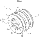
- FIG. 1 is a perspective view of the shaft bearing 1 according to the present invention.
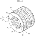
- FIGs. 2 and 3 are perspective views illustrating a disassembled state of the shaft bearing 1.
- the shaft bearing 1 according to the present invention is configured by combining a bearing 2, a cylindrical holder 3, and O-rings 4 which are a plurality of elastic rings.
- the bearing 2 is a ball bearing, and a conventional ball bearing can be selected and then used to suit to a shaft borne by the shaft bearing 1.
- the holder 3 has a cylindrical shape, and is configured by combining a first member 31 and a second member 32 which are two members divided parallel to an axial direction. The first member 31 and the second member 32 have the same shape, and are the same members.
- the first member 31 has one inner groove 33 formed on an inner peripheral surface in a peripheral direction, and three outer grooves 35 formed on an outer peripheral surface in the peripheral direction.
- the second member 32 also has one inner groove 34 formed on an inner peripheral surface in a peripheral direction, and three outer grooves 36 formed on an outer peripheral surface in the peripheral direction.
- the numbers of the outer grooves 35 and the outer grooves 36 are not limited to three, and can be suitably changed depending on the purpose, size, and others of the shaft bearing 1. Moreover, the outer grooves 35 and the outer grooves 36 having different depth and width can be arranged in parallel. It is also possible to provide more than one inner groove 33 and more than one inner groove 34, and a plurality of bearings 2 can be held, or one bearing 2 can be held by being selected from a plurality of inner grooves.
- the first member 31 has two depressions and two projections provided on the surface facing the second member 32 (not illustrated), and the second member 32 has two depressions 37 and two projections 38 provided on the surface facing the first member 31.
- the two depressions 37 are provided at one end of the second member 32, and the two projections 38 are provided at another end, whereas the two depressions and the two projections are provided at the same positions in the first member 31 as well. Accordingly, when the first member 31 and the second member 32 are to be combined, the depressions 37 of the second member 32 are put to face the projections of the first member 31, and the projections 38 of the second member 32 are put to face the depressions of the first member 31.
- the projections 38 of the second member 32 are inserted into the depressions of the first member 31, and the projections of the first member 31 are inserted into the depressions of the second member 32.
- the projections and the depressions are not particularly limited in number, position, and shape, and can be suitably changed.
- the holder 3 can be formed by resin, rubber, or metal (e.g., aluminum), and can have the inner peripheral surface thinned as illustrated in FIG. 3 for lighter weight.
- the dividing number of the holder 3 is not limited to two, but can be three or four. However, the holder 3 is preferably divided into the same size and the same shape in terms of manufacturing cost.
- the O-rings 4 have a size which can be stored in the three annular outer grooves on the outer peripheral surface of the holder 3. By inserting the O-rings 4 in at least one of the three annular outer grooves on the outer peripheral surface of the holder 3, the bearing 2 can be held in the holder 3, and the holder 3 can be kept in a cylindrical shape.
- an elastic ring is not limited to an O-ring, and has only to be able to fix the holder 3.
- a ring-shaped rubber band or the like can be used.
- the sectional shape of the annular outer grooves of the holder 3 can also be suitably changed to suit to the sectional shape of the elastic ring.
- the projections 38 of the second member 32 are inserted into the depressions of the first member 31, and the projections of the first member 31 are inserted into the depressions of the second member 32.
- the first member 31 and the second member 32 can be combined without misalignment.
- an outer peripheral part of the bearing 2 is stored in the inner groove 33 of the first member 31 and the inner groove 34 of the second member 32. Thereby, the bearing 2 is fixedly held onto the inner peripheral surface of the holder 3, as illustrated in FIG. 2 .
- the O-rings 4 are respectively inserted into the three annular outer grooves on the outer peripheral surface of the holder 3.
- the first member 31 and the second member 32 are fixed to each other by the O-rings 4, and the assembly of the shaft bearing 1 is completed, as illustrated in FIG. 1 .
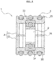
- the O-rings 4 are in a state where the outer peripheral surfaces thereof are outwardly projecting from the outer grooves 35 and 36. Then, when the shaft bearing 1 is assembled, the O-rings 4 do not need to be stored in all of the annular outer grooves. As illustrated in FIG. 5 , a press-fitting load of the shaft bearing 1 can be adjusted by changing the number of the O-rings 4 which are a plurality of elastic rings. Moreover, a press-fitting load of the shaft bearing 1 can also be adjusted by changing the thickness, shape, material, or the like of the elastic rings.
- the shaft bearing 1 can reduce rotational resistance more than when a conventional bush (slide bearing) is used. Moreover, the shaft bearing 1 can be reduced in weight by using the lightweight holder 3. Further, the shaft bearing 1 can bring about high advantageous effects of little off-center of a shaft, satisfactory workability of assembly, and a small required amount of oil (grease) during assembly.
- FIG. 6 is a schematic sectional view of a rod of a brush cutter when the shaft bearing 1 according to the present invention is used in the brush cutter.
- Three shaft bearings 1 are attached inside a pipe 6 of the rod, and thus a drive shaft 5 of the brush cutter is rotatably held by the shaft bearings 1.
- the shaft bearings 1 have the O-rings 4 partly projecting from the outer peripheral surface of the holder 3. Accordingly, the O-rings 4 contact the inner peripheral surface of the pipe 6, and the shaft bearings 1 are thus held in the pipe 6.
- the duration time of the battery can be longer by reducing rotational resistance of the drive shaft.
- the shaft bearing 1 is light in weight, and thus the brush cutter can also be reduced in weight.
- the shaft bearing 1 can also be used in a drive shaft of any machine other than a brush cutter.
- the shaft bearing 1 can adapt to various shafts by changing the bearing 2 to suit to a shaft to be borne. For example, as illustrated in FIG. 5 , by using a bearing 2' having the same outside diameter as the bearing 2 and having a smaller inside diameter, the shaft bearing 1 can adapt to a shaft having a small diameter, while the holder 3 and the O-ring 4 are the same components. In this way, while using the same holder 3 and O-ring 4, the shaft bearing 1 according to the present invention can adapt to shafts having different diameters by changing only bearings.
- the bearing 2' also has smaller width than the bearing 2, but can be stored in the inner groove on the inner peripheral surface of the holder 3, and therefore has structurally no problem.
- the shaft bearing 1 of the brush cutter according to the present invention can adapt to various shafts at low cost, and can easily adapt to a shaft of any machine other than a brush cutter as well.
Landscapes
- Engineering & Computer Science (AREA)
- General Engineering & Computer Science (AREA)
- Mechanical Engineering (AREA)
- Harvester Elements (AREA)
- Support Of The Bearing (AREA)
- Mounting Of Bearings Or Others (AREA)
Claims (5)
- Ein Bürstenschneider mit einem Antriebswellenlager (1), das ein Kugellager (2), eine zylindrische Halterung (3) und einen elastischen Ring (4) umfasst, wobei die Halterung (3) durch Kombinieren von zwei Elementen (31, 32) gebildet wird, die parallel zu einer axialen Richtung geteilt sind, und in einem Zustand zusammengebaut ist, in dem ein äußerer Umfangsteil des Lagers (2) in einer inneren Nut (33, 34) gelagert ist, die an einer inneren Umfangsfläche der Halterung in einer Umfangsrichtung ausgebildet ist, und der elastische Ring (4) in einer äußeren Nut (35, 36) gelagert ist, die an einer äußeren Umfangsfläche der Halterung in der Umfangsrichtung ausgebildet ist.
- Bürstenschneider gemäß Anspruch 1, wobei mehrere äußere Nuten (35, 36) der Halterung ausgebildet sind und der elastische Ring (4) in mindestens eine der äußeren Nuten eingesetzt ist.
- Bürstenschneider gemäß Anspruch 1 oder 2, wobei als elastischer Ring ein O-Ring verwendet wird.
- Bürstenschneider gemäß einem der Ansprüche 1 bis 3, wobei die geteilten Elemente der Halterung an ihren einander zugewandten Oberflächen mit einer Vertiefung (37) und einem Vorsprung (38) versehen sind und der Vorsprung eines der Elemente beim Zusammenbau der Halterung in die Vertiefung des anderen Elements eingesetzt wird.
- Bürstenschneider gemäß einem der Ansprüche 1 bis 4, wobei die Halterung aus Harz, Gummi oder Metall hergestellt ist.
Applications Claiming Priority (1)
| Application Number | Priority Date | Filing Date | Title |
|---|---|---|---|
| JP2019152817A JP7272648B2 (ja) | 2019-08-23 | 2019-08-23 | 軸受 |
Publications (2)
| Publication Number | Publication Date |
|---|---|
| EP3783238A1 EP3783238A1 (de) | 2021-02-24 |
| EP3783238B1 true EP3783238B1 (de) | 2022-11-30 |
Family
ID=68289835
Family Applications (1)
| Application Number | Title | Priority Date | Filing Date |
|---|---|---|---|
| EP19203105.2A Active EP3783238B1 (de) | 2019-08-23 | 2019-10-14 | Freischneider |
Country Status (3)
| Country | Link |
|---|---|
| US (1) | US20210054876A1 (de) |
| EP (1) | EP3783238B1 (de) |
| JP (1) | JP7272648B2 (de) |
Families Citing this family (1)
| Publication number | Priority date | Publication date | Assignee | Title |
|---|---|---|---|---|
| WO2025141709A1 (ja) * | 2023-12-26 | 2025-07-03 | マブチモーター株式会社 | 軸受保持構造及びモータ |
Citations (1)
| Publication number | Priority date | Publication date | Assignee | Title |
|---|---|---|---|---|
| DE2854566A1 (de) * | 1978-12-18 | 1980-06-19 | Beckman Instruments Gmbh | Schwingungsdaempfende lagerungs-anordnung einer rotierenden spindel |
Family Cites Families (10)
| Publication number | Priority date | Publication date | Assignee | Title |
|---|---|---|---|---|
| JPS6336740U (de) * | 1986-08-27 | 1988-03-09 | ||
| JPH01168126U (de) * | 1988-05-18 | 1989-11-27 | ||
| US5207512A (en) * | 1992-05-06 | 1993-05-04 | Dresser-Rand Company | Spherical roller bearing assembly |
| CA2182923C (en) * | 1995-08-10 | 2006-10-10 | Walter P. Waskiewicz | Bearing assembly insert |
| JP4188177B2 (ja) * | 2003-08-08 | 2008-11-26 | 株式会社共立 | 携帯式刈払機 |
| JP4867984B2 (ja) * | 2008-12-12 | 2012-02-01 | オイレス工業株式会社 | ブッシュ軸受 |
| JP2011075091A (ja) * | 2009-10-02 | 2011-04-14 | Ntn Corp | 軸受の分割外輪および分割外輪を備える軸受 |
| US9663137B2 (en) * | 2013-06-05 | 2017-05-30 | Nsk Ltd. | Guide bush and rack-and-pinion steering gear unit |
| JP2015008636A (ja) | 2013-06-26 | 2015-01-19 | 日立工機株式会社 | 携帯式作業機 |
| JP2016036341A (ja) | 2014-08-08 | 2016-03-22 | 株式会社末広工業 | 刈払機の駆動軸およびそれを備えた刈払機 |
-
2019
- 2019-08-23 JP JP2019152817A patent/JP7272648B2/ja active Active
- 2019-10-14 EP EP19203105.2A patent/EP3783238B1/de active Active
-
2020
- 2020-08-23 US US17/000,323 patent/US20210054876A1/en not_active Abandoned
Patent Citations (1)
| Publication number | Priority date | Publication date | Assignee | Title |
|---|---|---|---|---|
| DE2854566A1 (de) * | 1978-12-18 | 1980-06-19 | Beckman Instruments Gmbh | Schwingungsdaempfende lagerungs-anordnung einer rotierenden spindel |
Also Published As
| Publication number | Publication date |
|---|---|
| JP7272648B2 (ja) | 2023-05-12 |
| EP3783238A1 (de) | 2021-02-24 |
| JP2021032322A (ja) | 2021-03-01 |
| US20210054876A1 (en) | 2021-02-25 |
Similar Documents
| Publication | Publication Date | Title |
|---|---|---|
| US20120210810A1 (en) | Linear actuator | |
| GB2489441A (en) | A method of manufacturing a roller cage for a roller bearing and a roller bearing cage | |
| EP3569882B1 (de) | Zweireihiges selbstausrichtendes wälzlager | |
| EP2669540A1 (de) | Aus mehreren Bauteilen bestehender Wälzlagerkäfig und Wälzlager mit einem derartigen Käfig | |
| JP6993237B2 (ja) | 自動センタリングするコンパクトなフローティング・リーマ・ホルダ | |
| EP3783238A1 (de) | Wellenlager | |
| EP2540619B1 (de) | Verfahren zum Einbau eines Propellerblatts in eine Propellerblattanordnung | |
| JP2018066385A (ja) | アンギュラ玉軸受用保持器及びアンギュラ玉軸受並びに軸受装置 | |
| EP0044825A2 (de) | Unwichtausgleich für Drehwerkzeuge | |
| US12627199B2 (en) | Rotor balance ring and oil flinger | |
| JP5372563B2 (ja) | 内径研削工具 | |
| EP1789686B1 (de) | Hochgenaue spindelanordnung für eine automatische davenport-schraubmaschine | |
| US20200230768A1 (en) | Rotary indexing table with power-optimized drive | |
| JP2018105504A (ja) | アンギュラ玉軸受 | |
| KR101918585B1 (ko) | 탈착가능한 에어포일 쓰러스트 베어링 | |
| JP6572267B2 (ja) | 制限移動可能な軸を備えるモータ及び工作機械 | |
| EP2957390A1 (de) | Werkzeug zur montage eines axialwälzlagers | |
| KR20240031043A (ko) | 디버링 공구 | |
| CN209867377U (zh) | 一种绕线机用旋转主轴结构 | |
| EP0943238A2 (de) | Angelwinde | |
| US2420424A (en) | Hub construction | |
| CN222429286U (zh) | 一种高精度机床主轴装配结构 | |
| US9097281B2 (en) | Ball bearing particularly for use in high speed generator | |
| GB2249156A (en) | A bearing assembly for a universal joint | |
| JP2019065882A (ja) | 保持器付き針状ころ |
Legal Events
| Date | Code | Title | Description |
|---|---|---|---|
| PUAI | Public reference made under article 153(3) epc to a published international application that has entered the european phase |
Free format text: ORIGINAL CODE: 0009012 |
|
| STAA | Information on the status of an ep patent application or granted ep patent |
Free format text: STATUS: THE APPLICATION HAS BEEN PUBLISHED |
|
| AK | Designated contracting states |
Kind code of ref document: A1 Designated state(s): AL AT BE BG CH CY CZ DE DK EE ES FI FR GB GR HR HU IE IS IT LI LT LU LV MC MK MT NL NO PL PT RO RS SE SI SK SM TR |
|
| AX | Request for extension of the european patent |
Extension state: BA ME |
|
| STAA | Information on the status of an ep patent application or granted ep patent |
Free format text: STATUS: REQUEST FOR EXAMINATION WAS MADE |
|
| 17P | Request for examination filed |
Effective date: 20210713 |
|
| RBV | Designated contracting states (corrected) |
Designated state(s): AL AT BE BG CH CY CZ DE DK EE ES FI FR GB GR HR HU IE IS IT LI LT LU LV MC MK MT NL NO PL PT RO RS SE SI SK SM TR |
|
| STAA | Information on the status of an ep patent application or granted ep patent |
Free format text: STATUS: EXAMINATION IS IN PROGRESS |
|
| 17Q | First examination report despatched |
Effective date: 20220117 |
|
| GRAP | Despatch of communication of intention to grant a patent |
Free format text: ORIGINAL CODE: EPIDOSNIGR1 |
|
| STAA | Information on the status of an ep patent application or granted ep patent |
Free format text: STATUS: GRANT OF PATENT IS INTENDED |
|
| INTG | Intention to grant announced |
Effective date: 20220726 |
|
| GRAS | Grant fee paid |
Free format text: ORIGINAL CODE: EPIDOSNIGR3 |
|
| GRAA | (expected) grant |
Free format text: ORIGINAL CODE: 0009210 |
|
| STAA | Information on the status of an ep patent application or granted ep patent |
Free format text: STATUS: THE PATENT HAS BEEN GRANTED |
|
| AK | Designated contracting states |
Kind code of ref document: B1 Designated state(s): AL AT BE BG CH CY CZ DE DK EE ES FI FR GB GR HR HU IE IS IT LI LT LU LV MC MK MT NL NO PL PT RO RS SE SI SK SM TR |
|
| REG | Reference to a national code |
Ref country code: CH Ref legal event code: EP Ref country code: GB Ref legal event code: FG4D |
|
| REG | Reference to a national code |
Ref country code: AT Ref legal event code: REF Ref document number: 1534904 Country of ref document: AT Kind code of ref document: T Effective date: 20221215 |
|
| REG | Reference to a national code |
Ref country code: IE Ref legal event code: FG4D |
|
| REG | Reference to a national code |
Ref country code: DE Ref legal event code: R096 Ref document number: 602019022474 Country of ref document: DE |
|
| REG | Reference to a national code |
Ref country code: SE Ref legal event code: TRGR |
|
| REG | Reference to a national code |
Ref country code: LT Ref legal event code: MG9D |
|
| REG | Reference to a national code |
Ref country code: NL Ref legal event code: MP Effective date: 20221130 |
|
| PG25 | Lapsed in a contracting state [announced via postgrant information from national office to epo] |
Ref country code: PT Free format text: LAPSE BECAUSE OF FAILURE TO SUBMIT A TRANSLATION OF THE DESCRIPTION OR TO PAY THE FEE WITHIN THE PRESCRIBED TIME-LIMIT Effective date: 20230331 Ref country code: NO Free format text: LAPSE BECAUSE OF FAILURE TO SUBMIT A TRANSLATION OF THE DESCRIPTION OR TO PAY THE FEE WITHIN THE PRESCRIBED TIME-LIMIT Effective date: 20230228 Ref country code: LT Free format text: LAPSE BECAUSE OF FAILURE TO SUBMIT A TRANSLATION OF THE DESCRIPTION OR TO PAY THE FEE WITHIN THE PRESCRIBED TIME-LIMIT Effective date: 20221130 Ref country code: FI Free format text: LAPSE BECAUSE OF FAILURE TO SUBMIT A TRANSLATION OF THE DESCRIPTION OR TO PAY THE FEE WITHIN THE PRESCRIBED TIME-LIMIT Effective date: 20221130 Ref country code: ES Free format text: LAPSE BECAUSE OF FAILURE TO SUBMIT A TRANSLATION OF THE DESCRIPTION OR TO PAY THE FEE WITHIN THE PRESCRIBED TIME-LIMIT Effective date: 20221130 |
|
| REG | Reference to a national code |
Ref country code: AT Ref legal event code: MK05 Ref document number: 1534904 Country of ref document: AT Kind code of ref document: T Effective date: 20221130 |
|
| PG25 | Lapsed in a contracting state [announced via postgrant information from national office to epo] |
Ref country code: RS Free format text: LAPSE BECAUSE OF FAILURE TO SUBMIT A TRANSLATION OF THE DESCRIPTION OR TO PAY THE FEE WITHIN THE PRESCRIBED TIME-LIMIT Effective date: 20221130 Ref country code: PL Free format text: LAPSE BECAUSE OF FAILURE TO SUBMIT A TRANSLATION OF THE DESCRIPTION OR TO PAY THE FEE WITHIN THE PRESCRIBED TIME-LIMIT Effective date: 20221130 Ref country code: LV Free format text: LAPSE BECAUSE OF FAILURE TO SUBMIT A TRANSLATION OF THE DESCRIPTION OR TO PAY THE FEE WITHIN THE PRESCRIBED TIME-LIMIT Effective date: 20221130 Ref country code: IS Free format text: LAPSE BECAUSE OF FAILURE TO SUBMIT A TRANSLATION OF THE DESCRIPTION OR TO PAY THE FEE WITHIN THE PRESCRIBED TIME-LIMIT Effective date: 20230330 Ref country code: HR Free format text: LAPSE BECAUSE OF FAILURE TO SUBMIT A TRANSLATION OF THE DESCRIPTION OR TO PAY THE FEE WITHIN THE PRESCRIBED TIME-LIMIT Effective date: 20221130 Ref country code: GR Free format text: LAPSE BECAUSE OF FAILURE TO SUBMIT A TRANSLATION OF THE DESCRIPTION OR TO PAY THE FEE WITHIN THE PRESCRIBED TIME-LIMIT Effective date: 20230301 |
|
| PG25 | Lapsed in a contracting state [announced via postgrant information from national office to epo] |
Ref country code: NL Free format text: LAPSE BECAUSE OF FAILURE TO SUBMIT A TRANSLATION OF THE DESCRIPTION OR TO PAY THE FEE WITHIN THE PRESCRIBED TIME-LIMIT Effective date: 20221130 |
|
| PG25 | Lapsed in a contracting state [announced via postgrant information from national office to epo] |
Ref country code: SM Free format text: LAPSE BECAUSE OF FAILURE TO SUBMIT A TRANSLATION OF THE DESCRIPTION OR TO PAY THE FEE WITHIN THE PRESCRIBED TIME-LIMIT Effective date: 20221130 Ref country code: RO Free format text: LAPSE BECAUSE OF FAILURE TO SUBMIT A TRANSLATION OF THE DESCRIPTION OR TO PAY THE FEE WITHIN THE PRESCRIBED TIME-LIMIT Effective date: 20221130 Ref country code: EE Free format text: LAPSE BECAUSE OF FAILURE TO SUBMIT A TRANSLATION OF THE DESCRIPTION OR TO PAY THE FEE WITHIN THE PRESCRIBED TIME-LIMIT Effective date: 20221130 Ref country code: DK Free format text: LAPSE BECAUSE OF FAILURE TO SUBMIT A TRANSLATION OF THE DESCRIPTION OR TO PAY THE FEE WITHIN THE PRESCRIBED TIME-LIMIT Effective date: 20221130 Ref country code: CZ Free format text: LAPSE BECAUSE OF FAILURE TO SUBMIT A TRANSLATION OF THE DESCRIPTION OR TO PAY THE FEE WITHIN THE PRESCRIBED TIME-LIMIT Effective date: 20221130 Ref country code: AT Free format text: LAPSE BECAUSE OF FAILURE TO SUBMIT A TRANSLATION OF THE DESCRIPTION OR TO PAY THE FEE WITHIN THE PRESCRIBED TIME-LIMIT Effective date: 20221130 |
|
| PG25 | Lapsed in a contracting state [announced via postgrant information from national office to epo] |
Ref country code: SK Free format text: LAPSE BECAUSE OF FAILURE TO SUBMIT A TRANSLATION OF THE DESCRIPTION OR TO PAY THE FEE WITHIN THE PRESCRIBED TIME-LIMIT Effective date: 20221130 Ref country code: AL Free format text: LAPSE BECAUSE OF FAILURE TO SUBMIT A TRANSLATION OF THE DESCRIPTION OR TO PAY THE FEE WITHIN THE PRESCRIBED TIME-LIMIT Effective date: 20221130 |
|
| REG | Reference to a national code |
Ref country code: DE Ref legal event code: R097 Ref document number: 602019022474 Country of ref document: DE |
|
| PLBE | No opposition filed within time limit |
Free format text: ORIGINAL CODE: 0009261 |
|
| STAA | Information on the status of an ep patent application or granted ep patent |
Free format text: STATUS: NO OPPOSITION FILED WITHIN TIME LIMIT |
|
| 26N | No opposition filed |
Effective date: 20230831 |
|
| PG25 | Lapsed in a contracting state [announced via postgrant information from national office to epo] |
Ref country code: SI Free format text: LAPSE BECAUSE OF FAILURE TO SUBMIT A TRANSLATION OF THE DESCRIPTION OR TO PAY THE FEE WITHIN THE PRESCRIBED TIME-LIMIT Effective date: 20221130 |
|
| PGFP | Annual fee paid to national office [announced via postgrant information from national office to epo] |
Ref country code: SE Payment date: 20230918 Year of fee payment: 5 |
|
| PGFP | Annual fee paid to national office [announced via postgrant information from national office to epo] |
Ref country code: DE Payment date: 20230918 Year of fee payment: 5 |
|
| PG25 | Lapsed in a contracting state [announced via postgrant information from national office to epo] |
Ref country code: IT Free format text: LAPSE BECAUSE OF FAILURE TO SUBMIT A TRANSLATION OF THE DESCRIPTION OR TO PAY THE FEE WITHIN THE PRESCRIBED TIME-LIMIT Effective date: 20221130 Ref country code: MC Free format text: LAPSE BECAUSE OF FAILURE TO SUBMIT A TRANSLATION OF THE DESCRIPTION OR TO PAY THE FEE WITHIN THE PRESCRIBED TIME-LIMIT Effective date: 20221130 |
|
| REG | Reference to a national code |
Ref country code: CH Ref legal event code: PL |
|
| REG | Reference to a national code |
Ref country code: BE Ref legal event code: MM Effective date: 20231031 |
|
| PG25 | Lapsed in a contracting state [announced via postgrant information from national office to epo] |
Ref country code: LU Free format text: LAPSE BECAUSE OF NON-PAYMENT OF DUE FEES Effective date: 20231014 |
|
| GBPC | Gb: european patent ceased through non-payment of renewal fee |
Effective date: 20231014 |
|
| PG25 | Lapsed in a contracting state [announced via postgrant information from national office to epo] |
Ref country code: LU Free format text: LAPSE BECAUSE OF NON-PAYMENT OF DUE FEES Effective date: 20231014 |
|
| PG25 | Lapsed in a contracting state [announced via postgrant information from national office to epo] |
Ref country code: GB Free format text: LAPSE BECAUSE OF NON-PAYMENT OF DUE FEES Effective date: 20231014 |
|
| PG25 | Lapsed in a contracting state [announced via postgrant information from national office to epo] |
Ref country code: CH Free format text: LAPSE BECAUSE OF NON-PAYMENT OF DUE FEES Effective date: 20231031 |
|
| PG25 | Lapsed in a contracting state [announced via postgrant information from national office to epo] |
Ref country code: GB Free format text: LAPSE BECAUSE OF NON-PAYMENT OF DUE FEES Effective date: 20231014 Ref country code: FR Free format text: LAPSE BECAUSE OF NON-PAYMENT OF DUE FEES Effective date: 20231031 Ref country code: CH Free format text: LAPSE BECAUSE OF NON-PAYMENT OF DUE FEES Effective date: 20231031 |
|
| PG25 | Lapsed in a contracting state [announced via postgrant information from national office to epo] |
Ref country code: BE Free format text: LAPSE BECAUSE OF NON-PAYMENT OF DUE FEES Effective date: 20231031 |
|
| PG25 | Lapsed in a contracting state [announced via postgrant information from national office to epo] |
Ref country code: IE Free format text: LAPSE BECAUSE OF NON-PAYMENT OF DUE FEES Effective date: 20231014 |
|
| PG25 | Lapsed in a contracting state [announced via postgrant information from national office to epo] |
Ref country code: IE Free format text: LAPSE BECAUSE OF NON-PAYMENT OF DUE FEES Effective date: 20231014 |
|
| PG25 | Lapsed in a contracting state [announced via postgrant information from national office to epo] |
Ref country code: BG Free format text: LAPSE BECAUSE OF FAILURE TO SUBMIT A TRANSLATION OF THE DESCRIPTION OR TO PAY THE FEE WITHIN THE PRESCRIBED TIME-LIMIT Effective date: 20221130 |
|
| PG25 | Lapsed in a contracting state [announced via postgrant information from national office to epo] |
Ref country code: BG Free format text: LAPSE BECAUSE OF FAILURE TO SUBMIT A TRANSLATION OF THE DESCRIPTION OR TO PAY THE FEE WITHIN THE PRESCRIBED TIME-LIMIT Effective date: 20221130 |
|
| REG | Reference to a national code |
Ref country code: DE Ref legal event code: R119 Ref document number: 602019022474 Country of ref document: DE |
|
| REG | Reference to a national code |
Ref country code: SE Ref legal event code: EUG |
|
| PG25 | Lapsed in a contracting state [announced via postgrant information from national office to epo] |
Ref country code: DE Free format text: LAPSE BECAUSE OF NON-PAYMENT OF DUE FEES Effective date: 20250501 |
|
| PG25 | Lapsed in a contracting state [announced via postgrant information from national office to epo] |
Ref country code: CY Free format text: LAPSE BECAUSE OF FAILURE TO SUBMIT A TRANSLATION OF THE DESCRIPTION OR TO PAY THE FEE WITHIN THE PRESCRIBED TIME-LIMIT; INVALID AB INITIO Effective date: 20191014 |
|
| PG25 | Lapsed in a contracting state [announced via postgrant information from national office to epo] |
Ref country code: HU Free format text: LAPSE BECAUSE OF FAILURE TO SUBMIT A TRANSLATION OF THE DESCRIPTION OR TO PAY THE FEE WITHIN THE PRESCRIBED TIME-LIMIT; INVALID AB INITIO Effective date: 20191014 |
|
| PG25 | Lapsed in a contracting state [announced via postgrant information from national office to epo] |
Ref country code: SE Free format text: LAPSE BECAUSE OF NON-PAYMENT OF DUE FEES Effective date: 20241015 |
|
| PG25 | Lapsed in a contracting state [announced via postgrant information from national office to epo] |
Ref country code: TR Free format text: LAPSE BECAUSE OF FAILURE TO SUBMIT A TRANSLATION OF THE DESCRIPTION OR TO PAY THE FEE WITHIN THE PRESCRIBED TIME-LIMIT Effective date: 20221130 |