EP3783242B1 - Frein à disque pour véhicules, en particulier pour véhicules utilitaires, avec un actionneur électromécanique - Google Patents
Frein à disque pour véhicules, en particulier pour véhicules utilitaires, avec un actionneur électromécanique Download PDFInfo
- Publication number
- EP3783242B1 EP3783242B1 EP19193161.7A EP19193161A EP3783242B1 EP 3783242 B1 EP3783242 B1 EP 3783242B1 EP 19193161 A EP19193161 A EP 19193161A EP 3783242 B1 EP3783242 B1 EP 3783242B1
- Authority
- EP
- European Patent Office
- Prior art keywords
- spring
- plunger
- disc
- brake
- disc brake
- Prior art date
- Legal status (The legal status is an assumption and is not a legal conclusion. Google has not performed a legal analysis and makes no representation as to the accuracy of the status listed.)
- Active
Links
Images



Classifications
-
- F—MECHANICAL ENGINEERING; LIGHTING; HEATING; WEAPONS; BLASTING
- F16—ENGINEERING ELEMENTS AND UNITS; GENERAL MEASURES FOR PRODUCING AND MAINTAINING EFFECTIVE FUNCTIONING OF MACHINES OR INSTALLATIONS; THERMAL INSULATION IN GENERAL
- F16D—COUPLINGS FOR TRANSMITTING ROTATION; CLUTCHES; BRAKES
- F16D55/00—Brakes with substantially-radial braking surfaces pressed together in axial direction, e.g. disc brakes
- F16D55/02—Brakes with substantially-radial braking surfaces pressed together in axial direction, e.g. disc brakes with axially-movable discs or pads pressed against axially-located rotating members
- F16D55/22—Brakes with substantially-radial braking surfaces pressed together in axial direction, e.g. disc brakes with axially-movable discs or pads pressed against axially-located rotating members by clamping an axially-located rotating disc between movable braking members, e.g. movable brake discs or brake pads
- F16D55/224—Brakes with substantially-radial braking surfaces pressed together in axial direction, e.g. disc brakes with axially-movable discs or pads pressed against axially-located rotating members by clamping an axially-located rotating disc between movable braking members, e.g. movable brake discs or brake pads with a common actuating member for the braking members
- F16D55/225—Brakes with substantially-radial braking surfaces pressed together in axial direction, e.g. disc brakes with axially-movable discs or pads pressed against axially-located rotating members by clamping an axially-located rotating disc between movable braking members, e.g. movable brake discs or brake pads with a common actuating member for the braking members the braking members being brake pads
- F16D55/2255—Brakes with substantially-radial braking surfaces pressed together in axial direction, e.g. disc brakes with axially-movable discs or pads pressed against axially-located rotating members by clamping an axially-located rotating disc between movable braking members, e.g. movable brake discs or brake pads with a common actuating member for the braking members the braking members being brake pads in which the common actuating member is pivoted
-
- F—MECHANICAL ENGINEERING; LIGHTING; HEATING; WEAPONS; BLASTING
- F16—ENGINEERING ELEMENTS AND UNITS; GENERAL MEASURES FOR PRODUCING AND MAINTAINING EFFECTIVE FUNCTIONING OF MACHINES OR INSTALLATIONS; THERMAL INSULATION IN GENERAL
- F16D—COUPLINGS FOR TRANSMITTING ROTATION; CLUTCHES; BRAKES
- F16D65/00—Parts or details
- F16D65/14—Actuating mechanisms for brakes; Means for initiating operation at a predetermined position
-
- F—MECHANICAL ENGINEERING; LIGHTING; HEATING; WEAPONS; BLASTING
- F16—ENGINEERING ELEMENTS AND UNITS; GENERAL MEASURES FOR PRODUCING AND MAINTAINING EFFECTIVE FUNCTIONING OF MACHINES OR INSTALLATIONS; THERMAL INSULATION IN GENERAL
- F16D—COUPLINGS FOR TRANSMITTING ROTATION; CLUTCHES; BRAKES
- F16D65/00—Parts or details
- F16D65/02—Braking members; Mounting thereof
- F16D65/028—Rollers
-
- F—MECHANICAL ENGINEERING; LIGHTING; HEATING; WEAPONS; BLASTING
- F16—ENGINEERING ELEMENTS AND UNITS; GENERAL MEASURES FOR PRODUCING AND MAINTAINING EFFECTIVE FUNCTIONING OF MACHINES OR INSTALLATIONS; THERMAL INSULATION IN GENERAL
- F16D—COUPLINGS FOR TRANSMITTING ROTATION; CLUTCHES; BRAKES
- F16D65/00—Parts or details
- F16D65/02—Braking members; Mounting thereof
- F16D65/04—Bands, shoes or pads; Pivots or supporting members therefor
- F16D65/092—Bands, shoes or pads; Pivots or supporting members therefor for axially-engaging brakes, e.g. disc brakes
-
- F—MECHANICAL ENGINEERING; LIGHTING; HEATING; WEAPONS; BLASTING
- F16—ENGINEERING ELEMENTS AND UNITS; GENERAL MEASURES FOR PRODUCING AND MAINTAINING EFFECTIVE FUNCTIONING OF MACHINES OR INSTALLATIONS; THERMAL INSULATION IN GENERAL
- F16D—COUPLINGS FOR TRANSMITTING ROTATION; CLUTCHES; BRAKES
- F16D65/00—Parts or details
- F16D65/02—Braking members; Mounting thereof
- F16D65/04—Bands, shoes or pads; Pivots or supporting members therefor
- F16D65/092—Bands, shoes or pads; Pivots or supporting members therefor for axially-engaging brakes, e.g. disc brakes
- F16D65/095—Pivots or supporting members therefor
-
- F—MECHANICAL ENGINEERING; LIGHTING; HEATING; WEAPONS; BLASTING
- F16—ENGINEERING ELEMENTS AND UNITS; GENERAL MEASURES FOR PRODUCING AND MAINTAINING EFFECTIVE FUNCTIONING OF MACHINES OR INSTALLATIONS; THERMAL INSULATION IN GENERAL
- F16D—COUPLINGS FOR TRANSMITTING ROTATION; CLUTCHES; BRAKES
- F16D65/00—Parts or details
- F16D65/14—Actuating mechanisms for brakes; Means for initiating operation at a predetermined position
- F16D65/16—Actuating mechanisms for brakes; Means for initiating operation at a predetermined position arranged in or on the brake
- F16D65/18—Actuating mechanisms for brakes; Means for initiating operation at a predetermined position arranged in or on the brake adapted for drawing members together, e.g. for disc brakes
-
- F—MECHANICAL ENGINEERING; LIGHTING; HEATING; WEAPONS; BLASTING
- F16—ENGINEERING ELEMENTS AND UNITS; GENERAL MEASURES FOR PRODUCING AND MAINTAINING EFFECTIVE FUNCTIONING OF MACHINES OR INSTALLATIONS; THERMAL INSULATION IN GENERAL
- F16D—COUPLINGS FOR TRANSMITTING ROTATION; CLUTCHES; BRAKES
- F16D65/00—Parts or details
- F16D65/02—Braking members; Mounting thereof
- F16D2065/022—Rollers
-
- F—MECHANICAL ENGINEERING; LIGHTING; HEATING; WEAPONS; BLASTING
- F16—ENGINEERING ELEMENTS AND UNITS; GENERAL MEASURES FOR PRODUCING AND MAINTAINING EFFECTIVE FUNCTIONING OF MACHINES OR INSTALLATIONS; THERMAL INSULATION IN GENERAL
- F16D—COUPLINGS FOR TRANSMITTING ROTATION; CLUTCHES; BRAKES
- F16D2121/00—Type of actuator operation force
- F16D2121/18—Electric or magnetic
- F16D2121/20—Electric or magnetic using electromagnets
-
- F—MECHANICAL ENGINEERING; LIGHTING; HEATING; WEAPONS; BLASTING
- F16—ENGINEERING ELEMENTS AND UNITS; GENERAL MEASURES FOR PRODUCING AND MAINTAINING EFFECTIVE FUNCTIONING OF MACHINES OR INSTALLATIONS; THERMAL INSULATION IN GENERAL
- F16D—COUPLINGS FOR TRANSMITTING ROTATION; CLUTCHES; BRAKES
- F16D2121/00—Type of actuator operation force
- F16D2121/18—Electric or magnetic
- F16D2121/24—Electric or magnetic using motors
-
- F—MECHANICAL ENGINEERING; LIGHTING; HEATING; WEAPONS; BLASTING
- F16—ENGINEERING ELEMENTS AND UNITS; GENERAL MEASURES FOR PRODUCING AND MAINTAINING EFFECTIVE FUNCTIONING OF MACHINES OR INSTALLATIONS; THERMAL INSULATION IN GENERAL
- F16D—COUPLINGS FOR TRANSMITTING ROTATION; CLUTCHES; BRAKES
- F16D2125/00—Components of actuators
- F16D2125/18—Mechanical mechanisms
- F16D2125/20—Mechanical mechanisms converting rotation to linear movement or vice versa
- F16D2125/22—Mechanical mechanisms converting rotation to linear movement or vice versa acting transversely to the axis of rotation
- F16D2125/28—Cams; Levers with cams
-
- F—MECHANICAL ENGINEERING; LIGHTING; HEATING; WEAPONS; BLASTING
- F16—ENGINEERING ELEMENTS AND UNITS; GENERAL MEASURES FOR PRODUCING AND MAINTAINING EFFECTIVE FUNCTIONING OF MACHINES OR INSTALLATIONS; THERMAL INSULATION IN GENERAL
- F16D—COUPLINGS FOR TRANSMITTING ROTATION; CLUTCHES; BRAKES
- F16D2125/00—Components of actuators
- F16D2125/18—Mechanical mechanisms
- F16D2125/20—Mechanical mechanisms converting rotation to linear movement or vice versa
- F16D2125/22—Mechanical mechanisms converting rotation to linear movement or vice versa acting transversely to the axis of rotation
- F16D2125/28—Cams; Levers with cams
- F16D2125/32—Cams; Levers with cams acting on one cam follower
-
- F—MECHANICAL ENGINEERING; LIGHTING; HEATING; WEAPONS; BLASTING
- F16—ENGINEERING ELEMENTS AND UNITS; GENERAL MEASURES FOR PRODUCING AND MAINTAINING EFFECTIVE FUNCTIONING OF MACHINES OR INSTALLATIONS; THERMAL INSULATION IN GENERAL
- F16D—COUPLINGS FOR TRANSMITTING ROTATION; CLUTCHES; BRAKES
- F16D65/00—Parts or details
- F16D65/0043—Brake maintenance and assembly, tools therefor
Definitions
- the invention relates to a disc brake with an electromechanical actuator for vehicles, in particular for commercial vehicles, comprising a brake disc, a brake carrier and a brake caliper of a vehicle for clamping the brake disc using brake pads.
- the electromechanical actuator includes a motor, a cam designed as a force transmission device, and a tappet designed as an actuating unit. Electromechanical actuators for applying brake pads for disc brakes are well known.
- the actuator is electrically driven with a motor coupled to the actuator via the power transmission.
- the power transmission device can be a cam which converts a rotating movement of the motor into a translational movement.
- the translational movement also known as linear movement, is transmitted to a rotary lever of the disc brake by means of a tappet that is operatively connected to the cam disk.
- the rotary lever clamps the brake disc during a braking process via a pressure piece and the brake pads.
- the tappet is not properly fixed in a housing of the electromechanical actuator after assembly, which is why the tappet can fall out of the rotary lever after positioning, with the result that the power transmission for clamping the brake disc is interrupted and the brake disc is not clamped can be.
- the DE 10 2017 004436 A1 discloses a disc brake with an electromechanical actuator for vehicles for clamping a brake disc.
- the electromechanical actuator has a cam disk and a tappet that is operatively connected to the cam disk along an axial axis. There is no provision for securing against a misalignment of the plunger after it has been installed and possible damage to the plunger, housing and cam disc associated therewith.
- EP 2 239 480 A1 and DE 10 2012 006090 A1 disclose a disk brake for commercial vehicles, the brake disk being applied pneumatically via an application unit with a rotary lever and a brake cylinder operatively connected to the rotary lever.
- JP 3 774003 B2 discloses an electromechanical actuator for a disc brake.
- a tappet is operatively connected to a cam disc and a pressure piece.
- the pressure piece has a dome-shaped receptacle for receiving the plunger.
- a cam disk of an electromechanical actuator of a disc brake has a stop and the stop is set up to fix the tappet in a starting position of the rotary lever, in the direction of an axial axis of the electromechanical actuator, opposite the cam disk.
- the starting position of the rotary lever is the position in which no braking is initiated by the driver. In other words, no force and therefore no torque is applied to the rotary lever of the disc brake.
- the stop clamps the rotary lever in the cam, the stop having two properties. On the one hand, the stop prevents an axial movement in the direction of the rotary lever.
- the stop serves as a support for the rotary lever, so that the rotary lever and a guide of the electromechanical actuator are arranged axially in one plane and the stop, together with another stop on the actuator housing, prevents a rotary movement about the rotary lever's own axis.
- the electromechanical actuator has a distance between a guide area of the tappet, for guiding the tappet along the axial axis, and a first inner wall of the guide area of the actuator housing, and the distance is designed to allow the tappet to move in an area starting from the starting position of the rotary lever, between 0° and 5°, particularly advantageously between 0° and 3°, can be moved about a ram axis.
- the plunger is arranged on the one hand in the cam. on the other hand the plunger is at a distance of between 0° and 5° from the first inner wall of the guide area of the actuator housing.
- the stop has a contact surface radially in the direction of the plunger. In the starting position of the rotary lever, the plunger is in contact with the contact surface.
- the contact surface facilitates the assembly of the ram, in particular the arrangement of the ram in a receptacle of the rotary lever. More precisely, the ram cannot tilt radially but remains in position axially so that the rotary lever can be easily placed in the ram's seat during assembly.
- the guide area of the actuator housing has a second inner wall on the front side, relative to the axial axis.
- the tappet rests against the second inner wall of the guide area of the actuator housing.
- the plunger is therefore clamped axially between the stop and the second inner wall of the guide area.
- a misalignment of the ram after assembly ie if the ram is not arranged in the receptacle of the rotary lever, is prevented by positioning the ram on the contact surface and positioning the ram on the second inner wall of the guide surface.
- the tappet does not jam between the rotary lever and the cam disk, and the cam disk and the housing of the electromechanical actuator are not damaged by the tappet.
- the tappet has a guide roller and a lever arm arranged axially in the direction of the rotary lever of the disc brake, the lever arm bearing against the contact surface in the initial position of the rotary lever.
- the guide roller guides the rotary lever along the cam and the lever arm serves as a link between the guide roller of the tappet and the rotary lever of the disc brake.
- the cam disk is embodied in the shape of a worm and that the stop is arranged radially at an outer end of the cam disk.
- the cam disk is arranged in the housing of the electromechanical actuator via a shaft with a drive of the electromechanical actuator. Between the stop and the shaft, the cam disk has a recess for receiving the guide roller of the tappet.
- the stop is a radial shoulder on the outside of the cam, and the radial shoulder and the side of the cam opposite the radial shoulder form a trough for receiving the plunger.
- a spring encloses the plunger.
- the spring is arranged axially with a first end stop on the actuator housing.
- the spring is arranged axially with a second end stop on the plunger.
- the spring is in turn designed to fix the tappet axially and radially in a starting position of the rotary lever.
- a development of the second embodiment has a spring receptacle for supporting the first end stop of the spring in the axial direction on.
- the spring retainer is located in the guide of the housing and in front of the rotary lever of the disc brake.
- the spring is a compression spring, with the compression spring being supported axially and radially on the spring receptacle.
- the spring seat is a spring plate.
- the spring plate has an opening in the middle for the lever arm of the tappet to pass through.
- the actuator housing to which the spring mount is attached, is an aluminum housing.
- an aluminum housing is light and easily deformable compared to cast steel.
- the guide it is possible for the guide to be easily adapted to the diameter of the spring retainer using a machining tool. It is also possible to rework the guide, for example by means of a milling tool, to arrange the spring mount.
- the electromechanical actuator of the disc brake has, tangentially along the tappet, a first spring and opposite the first spring, tangentially along the tappet, a second spring, the first spring and the second spring being designed to move the tappet axially and to keep radially in a starting position of the rotary lever.
- a spring is arranged on each axial side of the ram, which keeps the ram in position.
- the first spring and the second spring can be made of a metal material or a plastic.
- a guide roller of the tappet has, in relation to the axial axis, a first receiving bearing, perpendicularly and horizontally, for fixing an end stop of the first spring. Furthermore, the guide roller, based on the axial Axis, vertically and horizontally in the second receiving bearing for fixing an end stop of the second spring.
- the second receiving bearing is arranged axially parallel to the first receiving bearing.
- the ram is arranged between the first receiving bearing and the second receiving bearing. The ram with the guide roller is movable independently of the first receiving bearing and the second receiving bearing.
- the first receiving bearing and the second receiving bearing are not axially movable radially.
- the electromechanical actuator has a first spring holding element for receiving the end stop of the first spring.
- the electromechanical actuator has a second spring holding element for receiving the end stop of the second spring. Both the first spring holding element and the second spring holding element serve to ensure that the first spring and the second spring are axially tensioned and hold the plunger in position against falling out of the cam disc.
- the first spring retaining element is fixed radially on a first inner wall of the guide area of the actuator housing and the second spring retaining element is fixed radially on the first inner wall of the guide area of the actuator housing.
- the first spring retaining element is inserted radially into a groove in the guide of the electromechanical actuator, and the second spring retaining element is also inserted radially into a groove in the guide of the electromechanical actuator for positioning.
- the first spring retaining element is fixed to the first inner wall of the guide region of the actuator housing via a first screw connection and a first tongue-groove connection and that the second spring retaining element is fixed to the first inner wall of the guide area of the actuator housing via a second screw connection and a tongue and groove connection.
- the first spring retaining element is then fastened axially to the housing of the electromechanical actuator with a force fit via the first screw connection and the second spring retaining element is fastened axially with a force fit via the second screw connection to the housing of the electromechanical actuator.
- the first screw connection prevents the first spring holding element from twisting about the axial axis
- the second screw connection prevents the second spring holding element from twisting about the axial axis.
- the actuator housing is an aluminum housing.
- Aluminum housings are light and easy to deform with a machining tool.
- the 1 shows a disc brake 1 with an electromechanical actuator 2, wherein the electromechanical actuator 2 has an actuator housing 5.
- the electromechanical actuator 2 is flanged to the disc brake 1 along an axial axis A.
- the disc brake 1 has two brake pads 4, 4a which are held against falling out radially by means of a hold-down bracket 3.
- the disc brake 1 is divided into a brake carrier 40 for accommodating the brake pads 4, 4a and a brake caliper 41, the brake caliper 41 being mounted on the brake carrier 40 in an axially sliding manner via two guide bolts 42, 42a.
- the electromechanical actuator 2 tensions a brake disc 46 ( 2 ) via the brake pads 4, 4a, a pressure piece, not shown, and with an in Figure 2a rotary lever 7 shown.
- a cam disk 10 is arranged in the electromechanical actuator 2 via a shaft 6 , the cam disk 10 being aligned along the axial axis A and being movable in a rotating manner about the shaft 6 .
- the actuator housing 5 has a cylindrical guide area 12 for guiding a plunger 8 along the axial axis A on the inside.
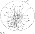
- the plunger 8 is arranged between a first inner wall 13 of the guide area 12, a second inner wall 13a of the guide area 12 arranged on the end face and the cam disk 10, with a lever arm 8b of the plunger 8 only partially is arranged between the first inner wall 13 of the guide region 12 and the cam disk 10 and the lever arm 8b rests radially on a contact surface 14 of a stop 11 of the cam disk 10, ie is supported radially on the stop 11.
- the stop 11 is arranged at an outer end 15 of the cam disk 10 .
- the cam disk 10 and the stop 11 are one component.
- the plunger 8 is limited axially by the second inner wall 13a of the guide region 12 and the stop 11 .
- the plunger 8 also has a guide roller 8a for guiding the plunger 8 along the cam disk 10 .
- the guide area 12 is designed geometrically in the radial direction in such a way that the ram 8 has a limited freedom of movement about a ram axis AS in the zero position.
- the starting position S of the tappet 8 is defined as the zero position, with no braking process, ie the brake disc 46 being clamped by the brake pads 4, 4a, taking place.
- the plunger 8 rests radially on the cam disc 10 .
- a distance L ( Figure 2a ) between a sliding chamfer 44 of the tappet 8 and the first inner wall 13 of the guide region 12 of the actuator housing 5 is so small that the tappet 8 has a freedom of movement about a tappet axis AS of at most 3° in the zero position, which counteracts jamming of the tappet 8.
- the plunger 8 in a second embodiment 3 are held in position by a spring 20.
- 3 shows the position of the plunger 8 and the spring 20 in the starting position S of the rotary lever 7 ( Fig.2a ).
- the spring 20 is fastened axially to a spring seat 21 via a first end stop 20a.
- the spring receptacle 21 designed as a plate spring is supported radially on the first inner wall 13 of the guide area 12 of the actuator housing 5 .
- the spring receptacle 21 has an opening 21a for the axial passage of the lever arm 8a of the plunger 8.
- the spring 20 is pushed axially over the tappet 8 and is supported axially and radially on the lever arm 8b of the tappet 8 with a second end stop 20b.
- the plunger 8 is prevented from falling out axially, since the spring 20 during an axial movement of the plunger 8 in the direction of the rotary lever 7 ( Figure 2a ) exerts an axial counterforce in the direction of the cam disk 10 and prevents the tappet 8 from rotating about the tappet axis AS.
- Another possibility for positioning the plunger 8 of the electromechanical actuator 2 of the disc brake 1 1 shows 4 .
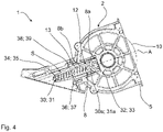
- the plunger 8 is held against falling out of the cam disk 10 via a first spring 30 arranged parallel with respect to the plunger 8 and a second spring 31 arranged in parallel opposite the first spring 30 .
- the second spring 31 has the same components as the first spring 30 .
- the components required for the arrangement of the second spring 31 are identical to the components of the first spring 30, which is why an example is shown in 4 only the side of the electromechanical actuator 2 with the first spring 30 is shown.
- the first spring 30 is on the ram side via a first end stop 30a of the spring 30 and via a first receiving bearing 32 on the shaft 6 ( 2 ) of the plunger 8 is arranged.
- the second spring 31 is arranged on the ram side via a second end stop 31a of the spring 31 and via a second receiving bearing 33 on the shaft 6 of the ram 8.
- the spring 31 is designed to fix the ram 8 axially and radially in a starting position of the rotary lever 7.
- the first receiving bearing 32 and the second receiving bearing 33 are movable and therefore not fixed to the shaft and compensate for a radial and/or axial movement of the plunger 8 triggered by a rotary movement of the cam disk 10 .
- the first spring 30 is held axially on the side opposite the first receiving bearing 32 via a first spring holding element 34 .
- the second spring 31 is in turn held axially on the side opposite the second receiving bearing 33 via a second spring holding element 35 .
- the first spring holding member 34 and the second spring holding member 35 are made of metal material. After the installation of the first spring 30 on the first receiving bearing 32, the first spring retaining element 34 is first positioned radially on the guide area 12 of the actuator housing 5 via a first tongue-groove connection 38 and then via a first screw connection 36 on the first spring Groove connection 38 opposite side of the first spring retaining element 34 fixed axially to the actuator housing 5 by a force and form fit. The assembly described for the first spring 30 also applies to the second spring 32.
- the second spring retaining element 35 is first radially attached to the guide area 12 of the Positioned actuator housing 5 and then fixed via a second screw connection 37 on the opposite side of the second spring-groove connection 39 of the second spring retaining element 35 axially on the actuator housing 5 by a force and form fit.
Landscapes
- Engineering & Computer Science (AREA)
- General Engineering & Computer Science (AREA)
- Mechanical Engineering (AREA)
- Braking Arrangements (AREA)
Claims (15)
- Frein à disque (1) comprenant un actionneur électromécanique (2) pour véhicules, en particulier pour véhicules utilitaires, pour le serrage d'un disque de frein (46) par le biais d'un levier rotatif (7) et de deux garnitures de frein (4, 4a), et l'actionneur électromécanique (2) comprenant un boîtier d'actionneur (5), un disque à came (10) disposé dans le boîtier d'actionneur (5) sur un arbre (6) et un poussoir (8) coopérant avec le disque à came (10) le long d'un axe axial (A), caractérisé en ce que le disque à came (10) présente une butée (11) et la butée (11) est conçue pour fixer le poussoir (8) dans une position de départ (S) du levier rotatif (7) en direction d'un axe axial (A) de l'actionneur électromécanique (2), à l'opposé du disque à came (10).
- Frein à disque (1) selon la revendication 1, caractérisé en ce que l'actionneur électromécanique (2) présente un espacement (L) entre un biseau de glissement (44) du poussoir (8), une région de guidage (12) du poussoir (8), servant au guidage du poussoir (8) le long de l'axe axial (A), et une première paroi interne (13) d'une région de guidage (12) du boîtier d'actionneur (5), et l'espacement (L) est configuré pour que le poussoir (8) soit déplaçable dans une plage, à partir de la position de départ (S) du levier rotatif (7), d'entre 0° et 5° autour d'un axe de poussoir (AS).
- Frein à disque (1) selon la revendication 1 ou 2, caractérisé en ce que la butée (11) présente, radialement en direction du poussoir (8), une surface d'appui (14) et le poussoir (8) repose sur la surface d'appui (14) dans la position de départ (S) et la région de guidage (12) du boîtier d'actionneur (5) présentant du côté frontal, par rapport à l'axe axial (A), une deuxième paroi interne (13a) et le poussoir (8) s'appuyant contre la deuxième paroi interne (13a) de la région de guidage (12) du boîtier d'actionneur (5) dans la position de départ (S).
- Frein à disque (1) selon la revendication 3, caractérisé en ce que le poussoir (8) présente un rouleau de guidage (8a) et un bras de levier (8b) disposé axialement en direction du levier rotatif (7) du frein à disque (1) et le bras de levier (8b) s'appuie radialement contre la surface d'appui (14) dans la position de départ (S) .
- Frein à disque (1) selon l'une des revendications précédentes, caractérisé en ce que le disque à came (10) est réalisé sous forme hélicoïdale et en ce que la butée (11) est disposée radialement à une extrémité extérieure (15) du disque à came (10).
- Frein à disque (1) comprenant un actionneur électromécanique (2) pour véhicules, en particulier pour véhicules utilitaires, pour le serrage d'un disque de frein (46) par le biais d'un levier rotatif (7) et de deux garnitures de frein (4, 4a), et l'actionneur électromécanique (2) comprenant un boîtier d'actionneur (5), un disque à came (10) disposé dans le boîtier d'actionneur (5) sur un arbre (6) et un poussoir (8) coopérant avec le disque à came (10) le long d'un axe axial (A), caractérisé en ce qu'un ressort (20) entoure le poussoir (8), le ressort (20) est disposé axialement par une première butée de fin de course (20a) sur le boîtier d'actionneur (5), le ressort (20) est disposé axialement par une deuxième butée de fin de course (20b) sur le poussoir (8) et le ressort (20) est réalisé pour fixer le poussoir (8) axialement et radialement dans une position de départ (S) du levier rotatif (7).
- Frein à disque (1) selon la revendication 6, caractérisé en ce que le boîtier d'actionneur (5) présente un logement de ressort (21) et le logement de ressort (21) est réalisé pour supporter la première butée de fin de course (20a) du ressort (20) dans la direction axiale.
- Frein à disque (1) selon la revendication 7, caractérisé en ce que le logement de ressort (21) est une coupelle de ressort (21) et la coupelle de ressort (21) présente une ouverture (21a) servant au passage du poussoir (8).
- Frein à disque (1) selon l'une des revendications 6 à 8, caractérisé en ce que le ressort (20) est un ressort de compression (20).
- Frein à disque (1) comprenant un actionneur électromécanique (2) pour véhicules, en particulier pour véhicules utilitaires, pour le serrage d'un disque de frein (46) par le biais d'un levier rotatif (7) et de deux garnitures de frein (4, 4a), et l'actionneur électromécanique (2) comprenant un boîtier d'actionneur (5), un disque à came (10) disposé dans le boîtier d'actionneur (5) sur un arbre (6) et un poussoir (8) coopérant avec le disque à came (10) le long d'un axe axial (A), caractérisé en ce qu'un premier ressort (30) et un deuxième ressort (31) opposé au premier ressort (30) et disposé parallèlement sont disposés tangentiellement le long du poussoir (8), l'un parmi le premier ressort (30) et le deuxième ressort (31) étant disposé respectivement au niveau d'un côté axial du poussoir (8) et le premier ressort (30) et le deuxième ressort (31) étant réalisés pour retenir le poussoir (8) axialement et radialement dans une position de départ (S) du levier rotatif (7).
- Frein à disque (1) selon la revendication 10, caractérisé en ce qu'un rouleau de guidage (8a) du poussoir (8) présente, par rapport à l'axe axial (A), perpendiculairement et horizontalement, un premier palier de logement (32) servant à la fixation d'une butée de fin de course (30a) du premier ressort (30) et en ce que le rouleau de guidage (8a) présente, par rapport à l'axe axial (A), perpendiculairement et horizontalement, un deuxième palier de logement (33) servant à la fixation d'une butée de fin de course (31a) du deuxième ressort (31) .
- Frein à disque (1) selon la revendication 10 ou 11, caractérisé en ce que l'actionneur électromécanique (2) présente un premier élément de retenue de ressort (34) servant au logement de la butée de fin de course (30a) du premier ressort (30) et en ce que l'actionneur électromécanique (2) présente un deuxième élément de retenue de ressort (35) servant au logement de la butée de fin de course (31a) du deuxième ressort (31).
- Frein à disque (1) selon l'une des revendications 10 à 12, caractérisé en ce que le premier élément de retenue de ressort (34) est fixé radialement à une première paroi interne (13) de la région de guidage (12) du boîtier d'actionneur (5) et en ce que le deuxième élément de retenue de ressort (35) est fixé radialement à la première paroi interne (13) de la région de guidage (12) du boîtier d'actionneur (5).
- Frein à disque selon la revendication 13, caractérisé en ce que le premier élément de retenue de ressort (34) est fixé par le biais d'une première liaison vissée (36) et d'une première liaison à rainure et languette (38) à la première paroi interne (13) de la région de guidage (12) du boîtier d'actionneur (5) et en ce que le deuxième élément de retenue de ressort (35) est fixé par le biais d'une deuxième liaison vissée (37) et d'une liaison à rainure et languette (39) à la première paroi interne (13) de la région de guidage (12) du boîtier d'actionneur (5).
- Frein à disque (1) selon l'une des revendications précédentes, caractérisé en ce que le boîtier d'actionneur (5) est un boîtier en aluminium (5).
Priority Applications (3)
| Application Number | Priority Date | Filing Date | Title |
|---|---|---|---|
| EP19193161.7A EP3783242B1 (fr) | 2019-08-22 | 2019-08-22 | Frein à disque pour véhicules, en particulier pour véhicules utilitaires, avec un actionneur électromécanique |
| US16/998,011 US12104665B2 (en) | 2019-08-22 | 2020-08-20 | Disc brake having an electromechanical actuator |
| CN202010849471.5A CN112413014B (zh) | 2019-08-22 | 2020-08-21 | 车辆的、尤其是商用车辆的具有机电促动器的盘式制动器 |
Applications Claiming Priority (1)
| Application Number | Priority Date | Filing Date | Title |
|---|---|---|---|
| EP19193161.7A EP3783242B1 (fr) | 2019-08-22 | 2019-08-22 | Frein à disque pour véhicules, en particulier pour véhicules utilitaires, avec un actionneur électromécanique |
Publications (2)
| Publication Number | Publication Date |
|---|---|
| EP3783242A1 EP3783242A1 (fr) | 2021-02-24 |
| EP3783242B1 true EP3783242B1 (fr) | 2022-12-28 |
Family
ID=67734587
Family Applications (1)
| Application Number | Title | Priority Date | Filing Date |
|---|---|---|---|
| EP19193161.7A Active EP3783242B1 (fr) | 2019-08-22 | 2019-08-22 | Frein à disque pour véhicules, en particulier pour véhicules utilitaires, avec un actionneur électromécanique |
Country Status (3)
| Country | Link |
|---|---|
| US (1) | US12104665B2 (fr) |
| EP (1) | EP3783242B1 (fr) |
| CN (1) | CN112413014B (fr) |
Families Citing this family (6)
| Publication number | Priority date | Publication date | Assignee | Title |
|---|---|---|---|---|
| DE102017004436A1 (de) * | 2017-05-09 | 2018-11-15 | Wabco Europe Bvba | Elektromechanischer Bremsenaktuator |
| EP3783242B1 (fr) * | 2019-08-22 | 2022-12-28 | ZF CV Systems Global GmbH | Frein à disque pour véhicules, en particulier pour véhicules utilitaires, avec un actionneur électromécanique |
| EP3783243B1 (fr) * | 2019-08-22 | 2022-12-28 | ZF CV Systems Global GmbH | Actionneur électromécanique de frein pour un frein à disque |
| US12379008B2 (en) * | 2019-12-05 | 2025-08-05 | Zf Cv Systems Europe Bv | Brake actuator, in particular electromechanical brake actuator of a commercial vehicle |
| DE102021115795A1 (de) | 2021-06-18 | 2022-12-22 | Bayerische Motoren Werke Aktiengesellschaft | Bremssattel einer elektromechanisch betreibbaren Reibungsbremse eines Fahrzeuges |
| DE102024115788A1 (de) * | 2024-06-06 | 2025-12-11 | Zf Cv Systems Global Gmbh | Elektromechanischer Bremsaktuator für eine Bremse eines Fahrzeugs |
Citations (1)
| Publication number | Priority date | Publication date | Assignee | Title |
|---|---|---|---|---|
| EP2239480B1 (fr) * | 2009-04-08 | 2012-07-11 | Knorr-Bremse Systeme für Nutzfahrzeuge GmbH | Frein à disque pour un véhicule utilitaire |
Family Cites Families (19)
| Publication number | Priority date | Publication date | Assignee | Title |
|---|---|---|---|---|
| DE1475501B2 (de) * | 1965-11-27 | 1972-01-27 | Alfred Teves Gmbh, 6000 Frankfurt | Mechanisch zu betaetigende teilbelagscheibenbremse mit selbstverstaerkender bremswirkung |
| US4154321A (en) * | 1977-03-14 | 1979-05-15 | Wagner Electric Corporation | Cam actuated disc brake |
| GB2039338B (en) * | 1978-12-09 | 1982-12-15 | Girling Ltd | Brake actuator |
| DE4409867C1 (de) * | 1994-03-22 | 1995-08-17 | Knorr Bremse Systeme | Bremsklotzeinheit für Schienenfahrzeuge |
| DE19506955C1 (de) * | 1995-02-28 | 1996-06-27 | Knorr Bremse Systeme | Bremszylinder |
| JP3774003B2 (ja) * | 1996-11-20 | 2006-05-10 | 株式会社日立製作所 | ディスクブレーキ |
| JPH11247910A (ja) * | 1998-03-04 | 1999-09-14 | Nisshinbo Ind Inc | ディスクブレーキ装置 |
| AT508296A1 (de) * | 2009-05-19 | 2010-12-15 | Ve Vienna Engineering Forschungs Und Entwicklungs Gmbh | Reibungsbremse |
| CN201496445U (zh) * | 2009-07-06 | 2010-06-02 | 厦门亨东制动系统有限公司 | 一种手刹线挂点一体式的后轮制动卡钳 |
| DE102011008272A1 (de) * | 2011-01-11 | 2012-07-12 | Knorr-Bremse Systeme für Nutzfahrzeuge GmbH | Selbstverstärkende Scheibenbremse mit pneumatischer oder elektromechanischer Betätigung |
| DE102012006090B4 (de) * | 2012-03-26 | 2017-11-16 | Knorr-Bremse Systeme für Nutzfahrzeuge GmbH | Scheibenbremse |
| US20170067522A1 (en) * | 2015-09-03 | 2017-03-09 | Bendix Spicer Foundation Brake Llc | Brake actuator apparatus for an air disc brake of a vehicle air braking system |
| DE102016207237B4 (de) * | 2016-04-28 | 2018-02-22 | Robert Bosch Gmbh | Aktuator zur Betätigung einer Kupplung eines Fahrzeugs |
| DE102016210757B3 (de) * | 2016-06-16 | 2017-06-01 | Siemens Aktiengesellschaft | Parkbremse und Betriebsverfahren |
| DE102017004436A1 (de) * | 2017-05-09 | 2018-11-15 | Wabco Europe Bvba | Elektromechanischer Bremsenaktuator |
| EP3431799B1 (fr) * | 2017-07-21 | 2022-05-25 | Meritor Heavy Vehicle Braking Systems (UK) Limited | Frein à disque |
| CN107237843B (zh) * | 2017-08-03 | 2022-12-27 | 安吉亚太制动系统有限公司 | 轻型商用车用浮动单楔式制动器 |
| EP3450788B1 (fr) * | 2017-08-31 | 2020-10-21 | Meritor Heavy Vehicle Braking Systems (UK) Limited | Frein à disque |
| EP3783242B1 (fr) * | 2019-08-22 | 2022-12-28 | ZF CV Systems Global GmbH | Frein à disque pour véhicules, en particulier pour véhicules utilitaires, avec un actionneur électromécanique |
-
2019
- 2019-08-22 EP EP19193161.7A patent/EP3783242B1/fr active Active
-
2020
- 2020-08-20 US US16/998,011 patent/US12104665B2/en active Active
- 2020-08-21 CN CN202010849471.5A patent/CN112413014B/zh active Active
Patent Citations (1)
| Publication number | Priority date | Publication date | Assignee | Title |
|---|---|---|---|---|
| EP2239480B1 (fr) * | 2009-04-08 | 2012-07-11 | Knorr-Bremse Systeme für Nutzfahrzeuge GmbH | Frein à disque pour un véhicule utilitaire |
Also Published As
| Publication number | Publication date |
|---|---|
| US20210054888A1 (en) | 2021-02-25 |
| EP3783242A1 (fr) | 2021-02-24 |
| US12104665B2 (en) | 2024-10-01 |
| CN112413014B (zh) | 2022-06-17 |
| CN112413014A (zh) | 2021-02-26 |
Similar Documents
| Publication | Publication Date | Title |
|---|---|---|
| EP3783242B1 (fr) | Frein à disque pour véhicules, en particulier pour véhicules utilitaires, avec un actionneur électromécanique | |
| DE112011101764B4 (de) | Reibungskupplung mit weggesteuerter Verschleißkompensation und Verfahren zu deren Montage | |
| DE2638508B2 (de) | Führung für den Sattel einer hydraulisch betätigbaren Schwimmsattelteilbelagscheibenbremse für Fahrzeuge | |
| EP4185784B1 (fr) | Procédé de production d'une unité d'engrenage | |
| EP2093127B1 (fr) | Mécanisme de direction doté d'un capteur | |
| DE102009014117A1 (de) | Klemmvorrichtung | |
| DE102018100458B4 (de) | Getriebegehäuseeinheit und Getriebeeinheit mit keilförmigem Ausgleichselement zum Axialspielausgleich | |
| WO2000005110A1 (fr) | Platine tubulaire pour systeme d'essuie-glace | |
| EP2659573B1 (fr) | Agrégat d'entraînement avec carter et dispositif permettant de monter un arbre dans le carter | |
| DE102004045218A1 (de) | Bremsenträger | |
| DE60205878T2 (de) | Brems-kupplung anordnung | |
| DE69409642T2 (de) | Schwimmsattel scheibenbremse | |
| EP1897660A2 (fr) | Elément de prise pour un tendeur à ressort et tendeur à ressort | |
| EP2620637A1 (fr) | Dispositif d'arrêt pour la transmission d'une éolienne ainsi que procédé d'arrêt de la transmission | |
| EP3835612A1 (fr) | Frein à disque, en particulier pour véhicules utilitaires et véhicule doté d'un frein à disque, en particulier véhicule utilitaire doté d'un frein à disque | |
| DE102014007568A1 (de) | Befestigungsanordnung eines Statorelements einer elektrischen Maschine an einem Bauelement, insbesondere für einen Kraftwagen | |
| EP4226063B1 (fr) | Frein électromagnétique et son procédé de fabrication | |
| EP1884676B1 (fr) | Dispositif d'embrayage, en particulier dispositif d'embrayage pour véhicule automobile | |
| DE102007027175A1 (de) | Hebelsystem sowie Verfahren zu dessen Montage | |
| DE202023100767U1 (de) | Balanciereinrichtung für eine Ausgleichseinheit, Balancer und Steuerung für eine Balanciereinrichtung und Set | |
| WO2009021904A1 (fr) | Machine électrique avec un dispositif de fixation d'un stator | |
| AT523278B1 (de) | Pyrotechnischer Aktuator | |
| EP0563689A2 (fr) | Frein à disque pour véhicule routier | |
| EP0974781A2 (fr) | Corps de vanne sans bride destiné à être monté entre des brides | |
| EP2933522B1 (fr) | Étrier de frein à disque et dispositif d'actionnement d'un tel étrier de frein à disque |
Legal Events
| Date | Code | Title | Description |
|---|---|---|---|
| PUAI | Public reference made under article 153(3) epc to a published international application that has entered the european phase |
Free format text: ORIGINAL CODE: 0009012 |
|
| STAA | Information on the status of an ep patent application or granted ep patent |
Free format text: STATUS: THE APPLICATION HAS BEEN PUBLISHED |
|
| AK | Designated contracting states |
Kind code of ref document: A1 Designated state(s): AL AT BE BG CH CY CZ DE DK EE ES FI FR GB GR HR HU IE IS IT LI LT LU LV MC MK MT NL NO PL PT RO RS SE SI SK SM TR |
|
| AX | Request for extension of the european patent |
Extension state: BA ME |
|
| RAP3 | Party data changed (applicant data changed or rights of an application transferred) |
Owner name: ZF CV SYSTEMS GLOBAL GMBH |
|
| STAA | Information on the status of an ep patent application or granted ep patent |
Free format text: STATUS: REQUEST FOR EXAMINATION WAS MADE |
|
| 17P | Request for examination filed |
Effective date: 20210824 |
|
| RBV | Designated contracting states (corrected) |
Designated state(s): AL AT BE BG CH CY CZ DE DK EE ES FI FR GB GR HR HU IE IS IT LI LT LU LV MC MK MT NL NO PL PT RO RS SE SI SK SM TR |
|
| REG | Reference to a national code |
Ref country code: DE Ref legal event code: R079 Ref document number: 502019006616 Country of ref document: DE Free format text: PREVIOUS MAIN CLASS: F16D0065000000 Ipc: F16D0055225500 |
|
| RIC1 | Information provided on ipc code assigned before grant |
Ipc: F16D 125/32 20120101ALN20220801BHEP Ipc: F16D 65/00 20060101ALN20220801BHEP Ipc: F16D 121/24 20120101ALN20220801BHEP Ipc: F16D 55/2255 20060101AFI20220801BHEP |
|
| GRAP | Despatch of communication of intention to grant a patent |
Free format text: ORIGINAL CODE: EPIDOSNIGR1 |
|
| STAA | Information on the status of an ep patent application or granted ep patent |
Free format text: STATUS: GRANT OF PATENT IS INTENDED |
|
| INTG | Intention to grant announced |
Effective date: 20221020 |
|
| GRAS | Grant fee paid |
Free format text: ORIGINAL CODE: EPIDOSNIGR3 |
|
| GRAA | (expected) grant |
Free format text: ORIGINAL CODE: 0009210 |
|
| STAA | Information on the status of an ep patent application or granted ep patent |
Free format text: STATUS: THE PATENT HAS BEEN GRANTED |
|
| AK | Designated contracting states |
Kind code of ref document: B1 Designated state(s): AL AT BE BG CH CY CZ DE DK EE ES FI FR GB GR HR HU IE IS IT LI LT LU LV MC MK MT NL NO PL PT RO RS SE SI SK SM TR |
|
| REG | Reference to a national code |
Ref country code: GB Ref legal event code: FG4D Free format text: NOT ENGLISH |
|
| REG | Reference to a national code |
Ref country code: CH Ref legal event code: EP |
|
| REG | Reference to a national code |
Ref country code: DE Ref legal event code: R096 Ref document number: 502019006616 Country of ref document: DE |
|
| REG | Reference to a national code |
Ref country code: AT Ref legal event code: REF Ref document number: 1540680 Country of ref document: AT Kind code of ref document: T Effective date: 20230115 |
|
| REG | Reference to a national code |
Ref country code: IE Ref legal event code: FG4D Free format text: LANGUAGE OF EP DOCUMENT: GERMAN |
|
| REG | Reference to a national code |
Ref country code: LT Ref legal event code: MG9D |
|
| PG25 | Lapsed in a contracting state [announced via postgrant information from national office to epo] |
Ref country code: SE Free format text: LAPSE BECAUSE OF FAILURE TO SUBMIT A TRANSLATION OF THE DESCRIPTION OR TO PAY THE FEE WITHIN THE PRESCRIBED TIME-LIMIT Effective date: 20221228 Ref country code: NO Free format text: LAPSE BECAUSE OF FAILURE TO SUBMIT A TRANSLATION OF THE DESCRIPTION OR TO PAY THE FEE WITHIN THE PRESCRIBED TIME-LIMIT Effective date: 20230328 Ref country code: LT Free format text: LAPSE BECAUSE OF FAILURE TO SUBMIT A TRANSLATION OF THE DESCRIPTION OR TO PAY THE FEE WITHIN THE PRESCRIBED TIME-LIMIT Effective date: 20221228 Ref country code: FI Free format text: LAPSE BECAUSE OF FAILURE TO SUBMIT A TRANSLATION OF THE DESCRIPTION OR TO PAY THE FEE WITHIN THE PRESCRIBED TIME-LIMIT Effective date: 20221228 |
|
| REG | Reference to a national code |
Ref country code: NL Ref legal event code: MP Effective date: 20221228 |
|
| PG25 | Lapsed in a contracting state [announced via postgrant information from national office to epo] |
Ref country code: RS Free format text: LAPSE BECAUSE OF FAILURE TO SUBMIT A TRANSLATION OF THE DESCRIPTION OR TO PAY THE FEE WITHIN THE PRESCRIBED TIME-LIMIT Effective date: 20221228 Ref country code: LV Free format text: LAPSE BECAUSE OF FAILURE TO SUBMIT A TRANSLATION OF THE DESCRIPTION OR TO PAY THE FEE WITHIN THE PRESCRIBED TIME-LIMIT Effective date: 20221228 Ref country code: HR Free format text: LAPSE BECAUSE OF FAILURE TO SUBMIT A TRANSLATION OF THE DESCRIPTION OR TO PAY THE FEE WITHIN THE PRESCRIBED TIME-LIMIT Effective date: 20221228 Ref country code: GR Free format text: LAPSE BECAUSE OF FAILURE TO SUBMIT A TRANSLATION OF THE DESCRIPTION OR TO PAY THE FEE WITHIN THE PRESCRIBED TIME-LIMIT Effective date: 20230329 |
|
| PG25 | Lapsed in a contracting state [announced via postgrant information from national office to epo] |
Ref country code: NL Free format text: LAPSE BECAUSE OF FAILURE TO SUBMIT A TRANSLATION OF THE DESCRIPTION OR TO PAY THE FEE WITHIN THE PRESCRIBED TIME-LIMIT Effective date: 20221228 |
|
| P01 | Opt-out of the competence of the unified patent court (upc) registered |
Effective date: 20230528 |
|
| PG25 | Lapsed in a contracting state [announced via postgrant information from national office to epo] |
Ref country code: SM Free format text: LAPSE BECAUSE OF FAILURE TO SUBMIT A TRANSLATION OF THE DESCRIPTION OR TO PAY THE FEE WITHIN THE PRESCRIBED TIME-LIMIT Effective date: 20221228 Ref country code: RO Free format text: LAPSE BECAUSE OF FAILURE TO SUBMIT A TRANSLATION OF THE DESCRIPTION OR TO PAY THE FEE WITHIN THE PRESCRIBED TIME-LIMIT Effective date: 20221228 Ref country code: PT Free format text: LAPSE BECAUSE OF FAILURE TO SUBMIT A TRANSLATION OF THE DESCRIPTION OR TO PAY THE FEE WITHIN THE PRESCRIBED TIME-LIMIT Effective date: 20230428 Ref country code: ES Free format text: LAPSE BECAUSE OF FAILURE TO SUBMIT A TRANSLATION OF THE DESCRIPTION OR TO PAY THE FEE WITHIN THE PRESCRIBED TIME-LIMIT Effective date: 20221228 Ref country code: EE Free format text: LAPSE BECAUSE OF FAILURE TO SUBMIT A TRANSLATION OF THE DESCRIPTION OR TO PAY THE FEE WITHIN THE PRESCRIBED TIME-LIMIT Effective date: 20221228 Ref country code: CZ Free format text: LAPSE BECAUSE OF FAILURE TO SUBMIT A TRANSLATION OF THE DESCRIPTION OR TO PAY THE FEE WITHIN THE PRESCRIBED TIME-LIMIT Effective date: 20221228 |
|
| PG25 | Lapsed in a contracting state [announced via postgrant information from national office to epo] |
Ref country code: SK Free format text: LAPSE BECAUSE OF FAILURE TO SUBMIT A TRANSLATION OF THE DESCRIPTION OR TO PAY THE FEE WITHIN THE PRESCRIBED TIME-LIMIT Effective date: 20221228 Ref country code: PL Free format text: LAPSE BECAUSE OF FAILURE TO SUBMIT A TRANSLATION OF THE DESCRIPTION OR TO PAY THE FEE WITHIN THE PRESCRIBED TIME-LIMIT Effective date: 20221228 Ref country code: IS Free format text: LAPSE BECAUSE OF FAILURE TO SUBMIT A TRANSLATION OF THE DESCRIPTION OR TO PAY THE FEE WITHIN THE PRESCRIBED TIME-LIMIT Effective date: 20230428 Ref country code: AL Free format text: LAPSE BECAUSE OF FAILURE TO SUBMIT A TRANSLATION OF THE DESCRIPTION OR TO PAY THE FEE WITHIN THE PRESCRIBED TIME-LIMIT Effective date: 20221228 |
|
| REG | Reference to a national code |
Ref country code: DE Ref legal event code: R097 Ref document number: 502019006616 Country of ref document: DE |
|
| PG25 | Lapsed in a contracting state [announced via postgrant information from national office to epo] |
Ref country code: DK Free format text: LAPSE BECAUSE OF FAILURE TO SUBMIT A TRANSLATION OF THE DESCRIPTION OR TO PAY THE FEE WITHIN THE PRESCRIBED TIME-LIMIT Effective date: 20221228 |
|
| PLBE | No opposition filed within time limit |
Free format text: ORIGINAL CODE: 0009261 |
|
| STAA | Information on the status of an ep patent application or granted ep patent |
Free format text: STATUS: NO OPPOSITION FILED WITHIN TIME LIMIT |
|
| 26N | No opposition filed |
Effective date: 20230929 |
|
| PG25 | Lapsed in a contracting state [announced via postgrant information from national office to epo] |
Ref country code: SI Free format text: LAPSE BECAUSE OF FAILURE TO SUBMIT A TRANSLATION OF THE DESCRIPTION OR TO PAY THE FEE WITHIN THE PRESCRIBED TIME-LIMIT Effective date: 20221228 |
|
| PG25 | Lapsed in a contracting state [announced via postgrant information from national office to epo] |
Ref country code: MC Free format text: LAPSE BECAUSE OF FAILURE TO SUBMIT A TRANSLATION OF THE DESCRIPTION OR TO PAY THE FEE WITHIN THE PRESCRIBED TIME-LIMIT Effective date: 20221228 |
|
| REG | Reference to a national code |
Ref country code: CH Ref legal event code: PL |
|
| PG25 | Lapsed in a contracting state [announced via postgrant information from national office to epo] |
Ref country code: MC Free format text: LAPSE BECAUSE OF FAILURE TO SUBMIT A TRANSLATION OF THE DESCRIPTION OR TO PAY THE FEE WITHIN THE PRESCRIBED TIME-LIMIT Effective date: 20221228 |
|
| PG25 | Lapsed in a contracting state [announced via postgrant information from national office to epo] |
Ref country code: LU Free format text: LAPSE BECAUSE OF NON-PAYMENT OF DUE FEES Effective date: 20230822 |
|
| PG25 | Lapsed in a contracting state [announced via postgrant information from national office to epo] |
Ref country code: LU Free format text: LAPSE BECAUSE OF NON-PAYMENT OF DUE FEES Effective date: 20230822 Ref country code: CH Free format text: LAPSE BECAUSE OF NON-PAYMENT OF DUE FEES Effective date: 20230831 |
|
| REG | Reference to a national code |
Ref country code: BE Ref legal event code: MM Effective date: 20230831 |
|
| REG | Reference to a national code |
Ref country code: IE Ref legal event code: MM4A |
|
| PG25 | Lapsed in a contracting state [announced via postgrant information from national office to epo] |
Ref country code: IT Free format text: LAPSE BECAUSE OF FAILURE TO SUBMIT A TRANSLATION OF THE DESCRIPTION OR TO PAY THE FEE WITHIN THE PRESCRIBED TIME-LIMIT Effective date: 20221228 |
|
| PG25 | Lapsed in a contracting state [announced via postgrant information from national office to epo] |
Ref country code: IE Free format text: LAPSE BECAUSE OF NON-PAYMENT OF DUE FEES Effective date: 20230822 |
|
| PG25 | Lapsed in a contracting state [announced via postgrant information from national office to epo] |
Ref country code: IE Free format text: LAPSE BECAUSE OF NON-PAYMENT OF DUE FEES Effective date: 20230822 |
|
| PG25 | Lapsed in a contracting state [announced via postgrant information from national office to epo] |
Ref country code: BE Free format text: LAPSE BECAUSE OF NON-PAYMENT OF DUE FEES Effective date: 20230831 |
|
| PGFP | Annual fee paid to national office [announced via postgrant information from national office to epo] |
Ref country code: DE Payment date: 20240625 Year of fee payment: 6 |
|
| PGFP | Annual fee paid to national office [announced via postgrant information from national office to epo] |
Ref country code: GB Payment date: 20240701 Year of fee payment: 6 |
|
| PGFP | Annual fee paid to national office [announced via postgrant information from national office to epo] |
Ref country code: FR Payment date: 20240702 Year of fee payment: 6 |
|
| PG25 | Lapsed in a contracting state [announced via postgrant information from national office to epo] |
Ref country code: BG Free format text: LAPSE BECAUSE OF FAILURE TO SUBMIT A TRANSLATION OF THE DESCRIPTION OR TO PAY THE FEE WITHIN THE PRESCRIBED TIME-LIMIT Effective date: 20221228 |
|
| PG25 | Lapsed in a contracting state [announced via postgrant information from national office to epo] |
Ref country code: BG Free format text: LAPSE BECAUSE OF FAILURE TO SUBMIT A TRANSLATION OF THE DESCRIPTION OR TO PAY THE FEE WITHIN THE PRESCRIBED TIME-LIMIT Effective date: 20221228 |
|
| PG25 | Lapsed in a contracting state [announced via postgrant information from national office to epo] |
Ref country code: CY Free format text: LAPSE BECAUSE OF FAILURE TO SUBMIT A TRANSLATION OF THE DESCRIPTION OR TO PAY THE FEE WITHIN THE PRESCRIBED TIME-LIMIT; INVALID AB INITIO Effective date: 20190822 |
|
| PG25 | Lapsed in a contracting state [announced via postgrant information from national office to epo] |
Ref country code: HU Free format text: LAPSE BECAUSE OF FAILURE TO SUBMIT A TRANSLATION OF THE DESCRIPTION OR TO PAY THE FEE WITHIN THE PRESCRIBED TIME-LIMIT; INVALID AB INITIO Effective date: 20190822 |
|
| REG | Reference to a national code |
Ref country code: AT Ref legal event code: MM01 Ref document number: 1540680 Country of ref document: AT Kind code of ref document: T Effective date: 20240822 |
|
| PG25 | Lapsed in a contracting state [announced via postgrant information from national office to epo] |
Ref country code: AT Free format text: LAPSE BECAUSE OF NON-PAYMENT OF DUE FEES Effective date: 20240822 |
|
| PG25 | Lapsed in a contracting state [announced via postgrant information from national office to epo] |
Ref country code: TR Free format text: LAPSE BECAUSE OF FAILURE TO SUBMIT A TRANSLATION OF THE DESCRIPTION OR TO PAY THE FEE WITHIN THE PRESCRIBED TIME-LIMIT Effective date: 20221228 |
|
| REG | Reference to a national code |
Ref country code: DE Ref legal event code: R119 Ref document number: 502019006616 Country of ref document: DE |
|
| PGFP | Annual fee paid to national office [announced via postgrant information from national office to epo] |
Ref country code: AT Payment date: 20260410 Year of fee payment: 5 |