EP3783257A1 - Modulares strahlformungssystem mit mehreren quellen - Google Patents
Modulares strahlformungssystem mit mehreren quellen Download PDFInfo
- Publication number
- EP3783257A1 EP3783257A1 EP20185099.7A EP20185099A EP3783257A1 EP 3783257 A1 EP3783257 A1 EP 3783257A1 EP 20185099 A EP20185099 A EP 20185099A EP 3783257 A1 EP3783257 A1 EP 3783257A1
- Authority
- EP
- European Patent Office
- Prior art keywords
- beam shaper
- automated luminaire
- luminaire
- module
- control circuit
- Prior art date
- Legal status (The legal status is an assumption and is not a legal conclusion. Google has not performed a legal analysis and makes no representation as to the accuracy of the status listed.)
- Pending
Links
Images





Classifications
-
- F—MECHANICAL ENGINEERING; LIGHTING; HEATING; WEAPONS; BLASTING
- F21—LIGHTING
- F21V—FUNCTIONAL FEATURES OR DETAILS OF LIGHTING DEVICES OR SYSTEMS THEREOF; STRUCTURAL COMBINATIONS OF LIGHTING DEVICES WITH OTHER ARTICLES, NOT OTHERWISE PROVIDED FOR
- F21V14/00—Controlling the distribution of the light emitted by adjustment of elements
- F21V14/06—Controlling the distribution of the light emitted by adjustment of elements by movement of refractors
-
- F—MECHANICAL ENGINEERING; LIGHTING; HEATING; WEAPONS; BLASTING
- F21—LIGHTING
- F21S—NON-PORTABLE LIGHTING DEVICES; SYSTEMS THEREOF; VEHICLE LIGHTING DEVICES SPECIALLY ADAPTED FOR VEHICLE EXTERIORS
- F21S10/00—Lighting devices or systems producing a varying lighting effect
-
- F—MECHANICAL ENGINEERING; LIGHTING; HEATING; WEAPONS; BLASTING
- F21—LIGHTING
- F21W—INDEXING SCHEME ASSOCIATED WITH SUBCLASSES F21K, F21L, F21S and F21V, RELATING TO USES OR APPLICATIONS OF LIGHTING DEVICES OR SYSTEMS
- F21W2131/00—Use or application of lighting devices or systems not provided for in codes F21W2102/00-F21W2121/00
- F21W2131/40—Lighting for industrial, commercial, recreational or military use
- F21W2131/406—Lighting for industrial, commercial, recreational or military use for theatres, stages or film studios
-
- F—MECHANICAL ENGINEERING; LIGHTING; HEATING; WEAPONS; BLASTING
- F21—LIGHTING
- F21Y—INDEXING SCHEME ASSOCIATED WITH SUBCLASSES F21K, F21L, F21S and F21V, RELATING TO THE FORM OR THE KIND OF THE LIGHT SOURCES OR OF THE COLOUR OF THE LIGHT EMITTED
- F21Y2105/00—Planar light sources
- F21Y2105/10—Planar light sources comprising a two-dimensional [2D] array of point-like light-generating elements
- F21Y2105/14—Planar light sources comprising a two-dimensional [2D] array of point-like light-generating elements characterised by the overall shape of the two-dimensional [2D] array
- F21Y2105/18—Planar light sources comprising a two-dimensional [2D] array of point-like light-generating elements characterised by the overall shape of the two-dimensional [2D] array annular; polygonal other than square or rectangular, e.g. for spotlights or for generating an axially symmetrical light beam
-
- F—MECHANICAL ENGINEERING; LIGHTING; HEATING; WEAPONS; BLASTING
- F21—LIGHTING
- F21Y—INDEXING SCHEME ASSOCIATED WITH SUBCLASSES F21K, F21L, F21S and F21V, RELATING TO THE FORM OR THE KIND OF THE LIGHT SOURCES OR OF THE COLOUR OF THE LIGHT EMITTED
- F21Y2115/00—Light-generating elements of semiconductor light sources
- F21Y2115/10—Light-emitting diodes [LED]
Definitions
- the present disclosure generally relates to automated luminaire(s), specifically to a modular multisource beam shaper for use with an automated luminaire(s).
- Luminaires with automated and remotely controllable functionality are well known in the entertainment and architectural lighting markets. Such products are commonly used in theatres, television studios, concerts, theme parks, night clubs and other venues. A typical product will commonly provide control over the pan and tilt functions of the luminaire allowing the operator to control the direction the luminaire is pointing and thus the position of the light beam on the stage or in the studio. Typically this position control is done via control of the luminaire's position in two orthogonal rotational axes usually referred to as pan and tilt. Many products provide control over other parameters such as the intensity, color, focus, beam size, beam shape and beam pattern. The beam pattern is often provided by a stencil or slide called a gobo which may be a steel, aluminum, or etched glass pattern. The products manufactured by Robe Show Lighting such as the ColorSpot 700E are typical of the art.
- the optical systems of such luminaires may include a beam shaping optical element through which the light is constrained to pass.
- a beam shaping element may comprise an asymmetric or lenticular lens or collection of lenses that constrain a light beam that is symmetrical and circular in cross section to one that is asymmetrical and predominantly elliptical or rectangular in cross section.
- a prior art automated luminaire may contain a plurality of such beam shapers each of which may have a greater or lesser effect on the light beam and that may be overlapped to produce a composite effect.
- a weak beam shaper may constrain a circular beam that has a symmetrical beam angle of 20° in all directions into a primarily elliptical beam that has a major axis of 30° and a minor axis of 15°.
- a more powerful beam shaper may constrain a circular beam that has a symmetrical beam angle of 20° in all directions into a primarily elliptical beam that has a major axis of 40° and a minor axis of 10°. It is also common in prior art luminaires to provide the ability to rotate the beam shaper along the optical axis such that the resultant symmetrical elliptical beam may also be rotated.
- United States Patent No. 5,665,305 ; United States Patent No. 5,758,955 ; United States Patent No. 5,980,066 and United States Patent No. 6,048,080 disclose such a system where a plurality of discrete lens elements is used to control the shape of a light beam.
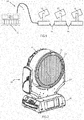
- FIG. 1 illustrates a typical multiparameter automated luminaire system 10.
- These systems commonly include a plurality of multiparameter automated luminaires 12 which typically each contain on-board a light source (not shown), light modulation devices, electric motors coupled to mechanical drive systems and control electronics (not shown).
- each automated luminaire 12 In addition to being connected to mains power either directly or through a power distribution system (not shown), each automated luminaire 12 is connected in series or in parallel to data link 14 to one or more control desks 15.
- the automated luminaire system 10 is typically controlled by an operator through the control desk 15.
- Prior art beam shapers often require installation internally within the luminaire and are not suitable for optical systems where an array of a number of discrete emitters, such as Light Emitting Diodes (LEDs), is used to produce the beam. Instead they rely on the optical path having a focus point that is small compared to the overall diameter of the beam in which the beam shaping can be situated.
- LEDs Light Emitting Diodes
- a beam shaper module is configured to be installed on or removed from an automated luminaire that produces a plurality of beams of light.
- the beam shaper module includes a housing, a beam shaper, one or more motors, and a control circuit.
- the housing is configured to detachably couple to a light emitting face of a luminaire head of the automated luminaire.
- the beam shaper includes an array of ribbed lenses, each ribbed lens extending across the beam shaper and receiving light from fewer than all of the beams of light.
- the motor(s) are configured to rotate the beam shaper about an axis of rotation that is coincident with an optical axis of the automated luminaire.
- the control circuit is configured to receive electrical power and control signals from the automated luminaire and, in response to the received control signals, to control rotation of the beam shaper using the motor(s).
- an automated luminaire in a second embodiment, includes a light source, a beam shaper module, and control electronics.
- the light source includes a plurality of LEDs and produces a plurality of beams of light that corresponds to the plurality of LEDs.
- the control electronics are configured to receive control signals via a data link.
- the beam shaper module includes a housing, a beam shaper that includes lenticular lenses extending across a first surface of the beam shaper, one or more motors, and a control circuit.
- the housing is configured to detachably couple to a light emitting face of a luminaire head of the automated luminaire.
- the beam shaper includes an array of ribbed lenses, each ribbed lens extending across the beam shaper and receiving light from fewer than all of the beams of light.
- the motor(s) are configured to rotate the beam shaper about an axis of rotation coincident with an optical axis of the automated luminaire.
- the control circuit is configured to receive electrical power from the automated luminaire and control signals from the automated luminaire's control electronics and, in response to the received control signals, to control rotation of the beam shaper using the one or more motor(s).
- the present disclosure generally relates to an automated luminaire, specifically to the configuration of a beam shaper within such a luminaire such that it provides the ability to adjust the size or eccentricity of the constrained light beam.
- FIG. 2 illustrates an embodiment of the beam shaping system mounted to an automated luminaire.
- Automated luminaire 20 comprises base box 25 on which is rotatably mounted yoke assembly 23 which is able to rotate in a first axis relative to base box 25.
- Luminaire head 22 is rotatably mounted to yoke 23 and is able to rotate in a second axis relative to yoke 23.
- Beam shaper 24 is mounted in rotatable frame 26 to the front of luminaire head 22. Beam shaper 24 may be rotated around the optical axis of luminaire head 22.
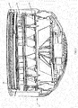
- Figure 3 illustrates a cross sectional view through luminaire head 22.
- An array of discrete LED emitters 30 and their associated individual optical systems 32 produce multiple beams of light each of which passes through beam shaper 24.
- Transmissive beam shaper 24 is mounted in rotatable frame 26 to the front of luminaire head 22. Beam shaper 24 may be rotated around the optical axis of luminaire head 22.
- beam shaper 24 may comprise a disk of optically transparent material such as glass, acrylic, or polycarbonate that is embossed or molded with a pattern or array of raised or lowered linear areas to form an array of ribbed or lenticular lenses.
- the cross section of that beam will be constrained to a cross section 17 that is asymmetrical and predominantly elliptical or rectangular in shape as shown in Figure 4 .
- Such a system may be rotated around an axis parallel with the optical axis of the luminaire to rotate the elliptical beam shown in Figure 4 to the position shown in Figure 5 .
- the beam shaper 24 may be continuously rotated a full 360° to produce any intermediate result. The user may choose and replace beam shaper 24 with different beam shapers that produce different results in the output beam.
- beam shapers that produce light beams with a greater or smaller eccentricity angle, asymmetric beam shapers that affect the beam in just one direction, prismatic beam shapers, diffusion beam shapers, holographic beam shapers, lenslet beam shapers, or other beam shapers as known in the art.
- the system could also be used as a beam diverter using a beam shaper that deflects the light axis through an angle.
- FIGS. 6 , 7 and 8 illustrate an embodiment of the beam shaping system removed from the luminaire for clarity.
- Beam shaper 24 is mounted within rotatable frame 26.
- Motor 40 drives shaft 42 and thus pinion gear 44.
- Pinion gear 44 in turn engages with and drives ring gear 46 which is part of rotatable frame 26.
- Rotatable frame 26 is free to rotate within bearings 48 that are mounted to fixed frame 27. Because of the large gear ratio between pinion gear 44 and ring gear 46, rotatable frame 26 may be rotated smoothly and positioned accurately.
- Motor 40 may be a stepper motor, or other motor known in the art such as a servo motor.
- Figures 9 and 10 illustrate an embodiment of the beam shaper as mounted to an automated luminaire.
- the beam shaper 24 is omitted to allow the construction to be seen.
- Pinion gear 44 engages with and drives ring gear 46 so as to rotate the beam shaper (omitted for clarity) in front of the array of LED output optics 32.
- Pinion gear 44 is small and does not materially interfere with the light beam from adjacent emitters, nor does the system cause any appreciable increase in the size of the automated luminaire.
- Such a system is extremely flexible, its position on the outside front of the automated luminaire makes it simple for the user to change the beam shaper to any design that they wish to achieve the desired effect. Alternatively, it can easily be completely removed to allow the system to revert back to its native beam shape.
- Figures 11-16 show embodiments of the beam shaper 24.
- Figures 11, 12 and 13 represent beam shapers having differing angles, where beam shaper 52 is a wide angle asymmetric lens array, beam shaper 54 is a medium angle asymmetric lens array, and beam shaper 56 is a narrow angle asymmetric lens array.
- Figures 14, 15 and 16 are examples of still other beam shapers that may be used.
- Beam shaper 58 is a grid array of lenticular lenses
- beam shaper 60 is a linear array of prisms forming an offset beam
- beam shaper 62 is a linear array of random angle prisms forming a complex asymmetric beam.
- the beam shaper 24 may be rotated so as to rotate the effect produced.
- the beam shaper 24 could be a portion of a disc instead of a full disc so that it only covers and affects a portion of the LEDs.
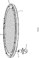
- FIG 17 illustrates a removable beam shaper module 1730 according to the disclosure attached to an automated luminaire 1720.
- the beam shaper is constructed as a module that may be installed on or removed from the automated luminaire 1720 as desired by the user.
- the automated luminaire 1720 comprises a base box 1725 on which is rotatably mounted a yoke assembly 1723, which is configured to rotate about a first axis relative to the base housing 1725.
- a luminaire head 1722 is rotatably mounted to the yoke 1723 and is able to rotate about a second axis relative to the yoke 1723.
- the beam shaper module 1730 is configured to detachably couple mechanically to the front (or light emitting face) of the luminaire head 1722.
- the beam shaper 1724 is mounted in a rotatable frame 1726 in the beam shaper module 1730.
- the beam shaper module 1730 is mounted concentrically with the luminaire head 1722 such that the beam shaper 1724 may be rotated around an optical axis of the luminaire head 1722.
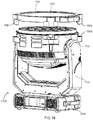
- Figure 18 illustrates the removable beam shaper module 1730 of Figure 17 removed from the automated luminaire 1720.
- the beam shaper module 1730 may be mechanically coupled to the luminaire head 1722 using springs, screws, pins, clips, magnets, or other suitable fastening means so that the beam shaper module 1730 may readily be attached or removed as a complete unit.
- the beam shaper module 1730 may be electrically connected to the luminaire head 1722 via cabling, connectors or other means well known in the art.
- an electrical cable may couple a first electrical connector of the beam shaper module 1730 to a second electrical connector of the luminaire head 1722.
- a first electrical connector 1802 of the beam shaper module 1730 may directly mate with a second electrical connector 1804 of the luminaire head 1722. These electrical connections are configured to provide electrical power and control signals to the beam shaping module 1730 from control electronics of the automated luminaire 1720.
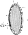
- FIG 19 presents an exploded view of the removable beam shaper module 1730 of Figure 17 .
- the beam shaper module 1730 comprises a housing 1906 that is configured to detachably couple mechanically to the luminaire head 1722.
- the housing 1906 includes a control circuit 1908, motors 1940, the rotatable frame 1726, the beam shaper 1724, and an electrical connector 1902.
- the motors 1940 drive the rotation of the rotatable frame 1726 through pinion gears 1944 mounted on the shafts of motors 1940.
- the pinion gears 1944 engage with gear teeth on an edge of the rotatable frame 1726.
- the motors 1940 may drive the rotatable frame 1726 through belts or pulley systems.
- the rotatable frame 1726 may be driven by fewer or more than the four motors 1940.
- the control circuit 1904 includes power supplies and circuits for motor control, sensor, and motor drivers and is configured to control the angle of rotation of rotation of the rotatable frame 1726 and thus the angle of rotation of the beam shaper 1724.
- the control circuit 1908 receives electrical power and control signals from the automated luminaire 1720 via the connector 1902.
- the control circuit 1908 may be electrically connected to the connector 1902 via cabling, connectors or other means well known in the art.
- an electrical cable may couple the control circuit 1908 to the connector 1902.
- an electrical connector of the control circuit 1908 may directly mate with the connector 1902.
- the control circuit 1908 is configured power the motors 1940 to rotate the rotatable frame 1726 and the beam shaper 1724 to a specified angle of rotation and/or at a specified rate of rotation.
- the control circuit 1908 includes a Hall sensor 1918 configured to sense a magnet 1916 that is mounted on the rotatable frame 1726.
- the magnet 1916 is a position indicator that provides the control circuit 1908 with an index indication of a known angle of rotation (position) of the rotatable frame 1726.
- the control circuit 1908 is configured to calibrate the angle of rotation of the rotatable frame 1726 at power up of the automated luminaire 1720 using the Hall sensor 1918 and the magnet 1916.
- other suitable sensors and position indicators including absolute position sensors and indicators configured to sense an absolute angle of rotation of the rotatable frame 1726 at power up, may be used.
- Figure 20 presents a back view of the removable modular beam shaper module 1730 of Figure 17 .
- the beam shaper module 1730 is shown assembled in Figure 20 and various elements of the beam shaper module 1730 that were previously described with reference to FigureS 17-19 are indicated.
Landscapes
- Engineering & Computer Science (AREA)
- General Engineering & Computer Science (AREA)
- Arrangement Of Elements, Cooling, Sealing, Or The Like Of Lighting Devices (AREA)
Applications Claiming Priority (1)
| Application Number | Priority Date | Filing Date | Title |
|---|---|---|---|
| US16/517,335 US10551038B2 (en) | 2012-03-18 | 2019-07-19 | Modular multisource beam shaping system |
Publications (1)
| Publication Number | Publication Date |
|---|---|
| EP3783257A1 true EP3783257A1 (de) | 2021-02-24 |
Family
ID=71575089
Family Applications (1)
| Application Number | Title | Priority Date | Filing Date |
|---|---|---|---|
| EP20185099.7A Pending EP3783257A1 (de) | 2019-07-19 | 2020-07-09 | Modulares strahlformungssystem mit mehreren quellen |
Country Status (1)
| Country | Link |
|---|---|
| EP (1) | EP3783257A1 (de) |
Cited By (1)
| Publication number | Priority date | Publication date | Assignee | Title |
|---|---|---|---|---|
| US12181144B2 (en) | 2024-01-30 | 2024-12-31 | Robe Lighting S.R.O. | Removable lens system for a luminaire |
Citations (5)
| Publication number | Priority date | Publication date | Assignee | Title |
|---|---|---|---|---|
| US5665305A (en) | 1995-11-13 | 1997-09-09 | Belliveau; Richard S. | Lighting system with multiple beam shapes |
| US5758955A (en) | 1995-07-11 | 1998-06-02 | High End Systems, Inc. | Lighting system with variable shaped beam |
| US5775799A (en) * | 1994-11-17 | 1998-07-07 | David W. Cunningham | Lighting device incorporating a zoomable beamspreader |
| US5980066A (en) | 1997-06-04 | 1999-11-09 | High End Systems, Inc. | Lighting system with multiple beam shapes |
| WO2005010433A1 (de) * | 2003-07-24 | 2005-02-03 | Johannes Jungel-Schmid | Raumleuchteneinrichtung |
-
2020
- 2020-07-09 EP EP20185099.7A patent/EP3783257A1/de active Pending
Patent Citations (6)
| Publication number | Priority date | Publication date | Assignee | Title |
|---|---|---|---|---|
| US5775799A (en) * | 1994-11-17 | 1998-07-07 | David W. Cunningham | Lighting device incorporating a zoomable beamspreader |
| US5758955A (en) | 1995-07-11 | 1998-06-02 | High End Systems, Inc. | Lighting system with variable shaped beam |
| US6048080A (en) | 1995-07-11 | 2000-04-11 | High End Systems, Inc. | Lighting system with variable shaped beam |
| US5665305A (en) | 1995-11-13 | 1997-09-09 | Belliveau; Richard S. | Lighting system with multiple beam shapes |
| US5980066A (en) | 1997-06-04 | 1999-11-09 | High End Systems, Inc. | Lighting system with multiple beam shapes |
| WO2005010433A1 (de) * | 2003-07-24 | 2005-02-03 | Johannes Jungel-Schmid | Raumleuchteneinrichtung |
Cited By (2)
| Publication number | Priority date | Publication date | Assignee | Title |
|---|---|---|---|---|
| US12181144B2 (en) | 2024-01-30 | 2024-12-31 | Robe Lighting S.R.O. | Removable lens system for a luminaire |
| EP4596960A1 (de) * | 2024-01-30 | 2025-08-06 | ROBE lighting s.r.o. | Abnehmbares linsensystem für eine leuchte |
Similar Documents
| Publication | Publication Date | Title |
|---|---|---|
| US10551038B2 (en) | Modular multisource beam shaping system | |
| US10514154B2 (en) | Multisource beam shaping system | |
| EP2694869B1 (de) | Doppelgraphikrad für eine automatisierte leuchte | |
| CN102483219B (zh) | 具有可旋转光形成器件的光效应系统 | |
| US9366415B2 (en) | Framing shutter system for a luminaire | |
| CN106322301B (zh) | 灯具 | |
| US8956014B2 (en) | Animation wheel for an automated luminaire | |
| JP6963123B2 (ja) | 制御可能な光出力特性を有する照明デバイス | |
| US10145524B2 (en) | Dual graphic wheel for an automated luminaire | |
| US20110103073A1 (en) | Beam shaper | |
| WO2015138483A2 (en) | Optical system for an led luminaire | |
| US20110103063A1 (en) | Optics for an automated luminaire | |
| US10845016B2 (en) | Coordinated effects system for an automated luminaire | |
| US11300797B2 (en) | Beam shaper | |
| US20180163950A9 (en) | Optics for an automated luminaire | |
| EP3058270B1 (de) | Verbessertes rahmenblendensystem für eine leuchte | |
| EP4614062A1 (de) | Lichteffektsystem | |
| GB2516039A (en) | Security Lighting |
Legal Events
| Date | Code | Title | Description |
|---|---|---|---|
| PUAI | Public reference made under article 153(3) epc to a published international application that has entered the european phase |
Free format text: ORIGINAL CODE: 0009012 |
|
| STAA | Information on the status of an ep patent application or granted ep patent |
Free format text: STATUS: REQUEST FOR EXAMINATION WAS MADE |
|
| 17P | Request for examination filed |
Effective date: 20200709 |
|
| AK | Designated contracting states |
Kind code of ref document: A1 Designated state(s): AL AT BE BG CH CY CZ DE DK EE ES FI FR GB GR HR HU IE IS IT LI LT LU LV MC MK MT NL NO PL PT RO RS SE SI SK SM TR |
|
| AX | Request for extension of the european patent |
Extension state: BA ME |
|
| STAA | Information on the status of an ep patent application or granted ep patent |
Free format text: STATUS: EXAMINATION IS IN PROGRESS |
|
| 17Q | First examination report despatched |
Effective date: 20211020 |
|
| RIC1 | Information provided on ipc code assigned before grant |
Ipc: F21Y 115/10 20160101ALN20250501BHEP Ipc: F21Y 105/18 20160101ALN20250501BHEP Ipc: F21W 131/406 20060101ALN20250501BHEP Ipc: F21V 14/06 20060101ALI20250501BHEP Ipc: F21S 10/00 20060101AFI20250501BHEP |