EP3783290B1 - Électronique de chaîne à led pour un appareil électroménager, appareil électroménager et procédé - Google Patents
Électronique de chaîne à led pour un appareil électroménager, appareil électroménager et procédé Download PDFInfo
- Publication number
- EP3783290B1 EP3783290B1 EP20186975.7A EP20186975A EP3783290B1 EP 3783290 B1 EP3783290 B1 EP 3783290B1 EP 20186975 A EP20186975 A EP 20186975A EP 3783290 B1 EP3783290 B1 EP 3783290B1
- Authority
- EP
- European Patent Office
- Prior art keywords
- fields
- led chain
- chain electronics
- setting
- selection
- Prior art date
- Legal status (The legal status is an assumption and is not a legal conclusion. Google has not performed a legal analysis and makes no representation as to the accuracy of the status listed.)
- Active
Links
Images


Classifications
-
- F—MECHANICAL ENGINEERING; LIGHTING; HEATING; WEAPONS; BLASTING
- F25—REFRIGERATION OR COOLING; COMBINED HEATING AND REFRIGERATION SYSTEMS; HEAT PUMP SYSTEMS; MANUFACTURE OR STORAGE OF ICE; LIQUEFACTION SOLIDIFICATION OF GASES
- F25D—REFRIGERATORS; COLD ROOMS; ICE-BOXES; COOLING OR FREEZING APPARATUS NOT OTHERWISE PROVIDED FOR
- F25D29/00—Arrangement or mounting of control or safety devices
-
- G—PHYSICS
- G06—COMPUTING OR CALCULATING; COUNTING
- G06F—ELECTRIC DIGITAL DATA PROCESSING
- G06F3/00—Input arrangements for transferring data to be processed into a form capable of being handled by the computer; Output arrangements for transferring data from processing unit to output unit, e.g. interface arrangements
- G06F3/01—Input arrangements or combined input and output arrangements for interaction between user and computer
- G06F3/03—Arrangements for converting the position or the displacement of a member into a coded form
- G06F3/033—Pointing devices displaced or positioned by the user, e.g. mice, trackballs, pens or joysticks; Accessories therefor
- G06F3/0354—Pointing devices displaced or positioned by the user, e.g. mice, trackballs, pens or joysticks; Accessories therefor with detection of two-dimensional [2D] relative movements between the device, or an operating part thereof, and a plane or surface, e.g. 2D mice, trackballs, pens or pucks
- G06F3/03547—Touch pads, in which fingers can move on a surface
-
- F—MECHANICAL ENGINEERING; LIGHTING; HEATING; WEAPONS; BLASTING
- F25—REFRIGERATION OR COOLING; COMBINED HEATING AND REFRIGERATION SYSTEMS; HEAT PUMP SYSTEMS; MANUFACTURE OR STORAGE OF ICE; LIQUEFACTION SOLIDIFICATION OF GASES
- F25D—REFRIGERATORS; COLD ROOMS; ICE-BOXES; COOLING OR FREEZING APPARATUS NOT OTHERWISE PROVIDED FOR
- F25D2400/00—General features of, or devices for refrigerators, cold rooms, ice-boxes, or for cooling or freezing apparatus not covered by any other subclass
- F25D2400/36—Visual displays
- F25D2400/361—Interactive visual displays
Definitions
- the invention relates to LED chain electronics for a household appliance, with a plurality of touch-sensitive control panels arranged in a row.
- the invention also relates to a household appliance with at least one such LED electronic chain.
- the invention also relates to a method for operating LED chain electronics.
- the invention is applicable to household refrigeration appliances, especially with a refrigerator part and a freezer part.
- Control panels arranged on the outside of a refrigerator door are known for operating refrigerators. In this case, it is desirable to keep the associated area small without reducing user-friendliness.
- This can be implemented, for example, by touch-sensitive TFT displays, in which the information displayed on the control panels can be variably adjusted.
- TFT displays have the disadvantage that they are still very expensive.
- So-called LED chain electronics are also known for use as control panels. These are typically elongate or strip-shaped strips with touch-sensitive control panels (also referred to as “touch panels” or “direct touch” control panels) arranged in a row in the longitudinal direction.
- the control panels can be designed as touch-sensitive layers or layer stacks that act, for example, as inductive proximity switches, capacitive proximity switches or electrical contact switches.
- the control panels can be individually backlit using at least one LED and, for example, are provided with a mask in order to allocate fixed lighting information to each control panel, e.g. in the form of letters, numbers, symbols, etc.
- an LED chain display can be used each position can only be occupied by a specific display field.
- a - rigid or flexible - printed circuit board or circuit board serves as the carrier of an LED chain electronics, on which, in addition to the touch-sensitive control panels and LEDs, a circuit or electronics for evaluating the control panels for touch, controlling the LEDs and, if necessary, triggering at least one action when touching the control panels is present.
- the WO 2017/071725 A1 discloses a touch switch for an operating device of an electrical household appliance.
- the EP 2 043 407 A1 discloses a control device for a household appliance with chain electronics in the form of a strip arranged one behind the other.
- the EP 3 330 617 A1 discloses a hob with a hob plate with touch sensors arranged below a longitudinal strip area and below a control panel, which are arranged next to one another in the longitudinal direction of the longitudinal strip area.
- the DE 10 2010 062485 B3 discloses a method for controlling a device with a control device with a control surface.
- the EP 2 392 859 A1 discloses a hob with control panels that can be individually backlit.
- a sufficiently large distance between the individual control panels is typical for LED chain electronics in order to ensure ergonomic operability.
- a separate LED chain electronics has been provided for each adjustable operating parameter, which still requires a large amount of space when there are several adjustable operating parameters, either by creating an operating device as a long line with several LED chain electronics arranged one behind the other or as a display field with several next to each other arranged LED chain electronics. It is the object of the present invention to at least partially overcome the disadvantages of the prior art and in particular to provide a particularly compact and yet easy to use and inexpensive LED chain electronics, especially for a household appliance.
- This LED chain electronics has the advantage that, with a particularly compact external shape, it provides a large number of control panels that can be reliably identified and operated, and can still be implemented inexpensively. In comparison to several separately arranged LED chain electronics with the same functionality, there can be a noticeable reduction of the base area can be achieved. It can also be specifically positioned in places where there is little space. In addition, a contemporary design with a subtle presence is achieved. In addition, such LED chain electronics are robust.
- a distance between the next but one adjacent setting fields of the same operating line is equal to or greater than a typical finger contact width and a distance between adjacent setting fields of the same operating line is smaller than the typical finger contact width.
- the above condition can also be formulated in such a way that a distance from the center of the setting field to the edge of the neighboring setting field in the same control column corresponds to at least half a finger contact width.
- a particularly compact arrangement is achieved because the distance between adjacent setting fields of the same operating line is smaller than the typical finger contact width.
- a "typical finger contact width” is understood to mean an extension of a contact surface with the LED chain electronics, which is typical for a finger of an adult, along its longitudinal extent when a control panel is actuated.
- the typical finger contact width is between 15 mm and 20 mm.
- a respective touch field is assigned to each control panel, or the same touch field is assigned to adjacent setting fields of different operating lines.
- the same or a common touch field is assigned to several selection fields and at least one of the selection fields can be selected by actuating the touch field several times. A user can then switch through or “toggle” one after the other between the displayed selection fields by repeatedly actuating the touch field.
- the currently selected selection field is indicated to a user by a brighter glow.
- several selection fields are provided as control panels that can be toggled through or selected one after the other.
- the LED chain electronics are set up in such a way that certain user-selectable control panels are visible or highlighted for a user and an associated, in particular fixed, function or action can be triggered by directly actuating (e.g. touching or pressing) a user-selectable control panel.
- the LED chain electronics and thus also its user interface is in particular in the form of a strip, in particular in a straight line, but in principle also e.g. curved, circular or free-form.
- the control panels are accordingly arranged in a row along the longitudinal extension of the LED chain electronics, in particular not overlapping.
- control panels include at least two selection fields, which, when activated, can be used exclusively by a user to select setting fields belonging to the same operating line, means in particular that further control panels of the LED chain electronics (which themselves are not selection fields) can only be selected by pressing a specific selection field be activated for a user. Because the control panels include at least two selection fields, the LED chain electronics also includes at least two control lines.
- a “service line” is understood to mean a set of control panels comprising a selection field and the control panels that can be selected by the user when this selection field is actuated and that do not themselves represent any selection fields.
- a service line includes at least one setting field that can be selected exclusively and can also include at least one combo box, as described in more detail below.
- the control panels of a control line represent a real subset of all control panels of the LED chain electronics. Different control lines differ in at least one control panel, in particular in their setting fields. In a further development, each of the operating lines has a number of setting fields.
- a setting field is used to set an associated device, in particular a household appliance.
- the fact that the setting fields of different operating lines are arranged alternately next to one another includes, in particular, that setting fields of different operating lines alternate along the strip-shaped longitudinal extension of the LED chain electronics. If there are more than two operating lines, the setting fields can always alternate in the same order.
- each control panel of the LED chain electronics can be individually backlit, the respective brightness can be set individually.
- the brightness comprises at least three different brightness levels: a lowest brightness, by means of which control fields that are not currently user-selectable are backlit, a medium brightness, by means of which control fields which are currently user-selectable but not selected are backlit, and a maximum brightness, by means of which control fields which are currently selected are backlit.
- control panels that are not currently user-selectable are not illuminated. This further increases usability for a user. In this case, only the brightness levels “dark”, “weak” and “bright” or similar exist.
- the circuitry or electronics of the LED chain electronics is set up to monitor the control panels for actuation and is set up to trigger an action associated with this control panel when a user-selectable control panel is actuated.
- the triggered action can include, for example, changing a brightness level of the operated and/or other control panels and/or can include sending a message that a specific control panel has been operated to an external unit (eg to a control device of a household appliance).
- At least one typical finger contact width is assigned to the selection fields, independently of the selection. This ensures that the selection fields are always assigned to a typical finger contact width, i.e. even if another selection field is currently selected. This assignment can be achieved in that a distance to adjacent selection fields is correspondingly large and/or the selection field itself is correspondingly wide. This can also be expressed in such a way that a distance from the center of the selection field to the edge of an adjacent selection field corresponds to at least half a finger contact width.
- the selection fields are always at least weakly backlit, ie are always backlit in normal operation or are never switched off.
- the setting fields of at least one of the same operating line are set up to select different values of a specific operating parameter.
- Possible operating parameters can include a temperature, a humidity, a power level, etc., for example.
- the fact that the setting fields are set up accordingly can include, for example, that their masks and thus the light information recognizable by a user when backlit is designed accordingly.
- the light information can be shaped as temperature values "2°C", “4°C", "6°C” and "8°C".
- the selection fields have or emit light information when they are backlit, which indicates the operating parameters that can be set using the setting fields of this operating line.
- the light information of the associated selection field can be displayed as "refrigerator part", "cooler”, etc.
- the LED chain electronics additionally have at least one control panel in the form of a combo box, which can be selected by the user for a number of selected control lines or is assigned to a number of control lines. Through this the same control panels occurring in several control lines need only be displayed once, which results in a further reduction in space and costs.
- the combo box can remain backlit or, alternatively, be deactivated briefly and then activated again.
- the LED chain electronics are provided or set up as an operating device for a household appliance.
- the object is also achieved by a household appliance that has at least one LED electronic chain as described above.
- the household appliance can be designed analogously to the LED chain electronics and has the same advantages.
- the household appliance is a cooling appliance. This achieves the advantage that due to the small size of the LED chain electronics, there is little weakening of the insulation.
- the operating parameters assigned to the operating lines include a temperature in the refrigerator part and a temperature in the freezer part.
- the LED chain electronics has at least one combo box that can be selected for setting corresponding functions or values for both parts, e.g. at least one "Super”, "Eco”, etc. combo box.
- the household appliance can also be any other household appliance, for example a cooking appliance, a dishwasher, a laundry treatment appliance or another large household appliance.
- the household appliance can also be a small household appliance such as a coffee machine, etc.
- the household appliance is in particular a kitchen appliance.
- the household appliance has at least one treatment room (e.g. a cold room, freezer room, cooking room, dishwashing room, laundry drum, etc.) and the LED chain electronics are arranged in a door closing the treatment room, in particular in or on an outside of the door.
- the LED chain electronics can be aligned horizontally or vertically, for example.
- the method can be designed analogously to the LED chain electronics and/or the household appliance and has the same advantages.
- setting fields associated with a selection field are brightly activated for selection (or simply "activated") means that these setting fields are backlit in a way that is recognizable to a user and an action can be triggered for them when the user presses them.
- the activated setting fields can glow dimly if the operation of the household appliance is changed or varied by the respective associated action, and glow brightly if the household appliance is currently already being operated according to the associated action.
- the associated cooling temperature can be set for a refrigerator when a selection field belonging to a refrigerator part or a freezer part is activated. To do this, the setting field that corresponds to the currently set cooling temperature lights up brightly, while the other setting fields only light up dimly.
- a selection field when actuated, it is set to be brightly lit, while the at least one other selection field is set to be faintly lit.
- the household appliance is set up as such to trigger a corresponding action or function by pressing a selectable setting field or - if available - combo box, e.g. changing a setpoint temperature, starting a quick cooling process, etc Controller of the household appliance have received a message from the LED chain electronics that a specific selectable setting field or - if available - combo box has been pressed and based on it adjust a control of the household appliance.
- Fig.6 shows a sketch of two linear LED chain electronics LK-1 and LK-2 arranged one behind the other in a plan view of their user interfaces for a refrigerator with a refrigerator part or “refrigerator compartment” and a freezer part or “freezer compartment”.
- the LED chain electronics LK-1 and LK-2 are arranged on the outside in a door of the refrigerator compartment.
- a first electronic chain of LEDs LK-1 is provided for setting a target cooling temperature of the refrigerator compartment and has a display panel 102 arranged one behind the other in the longitudinal extension L, four setting panels E1-1 to E1-4 for setting the associated target values and one setting panel E1-5 for Setting a special function to cool down the refrigerator compartment particularly quickly.
- the fields 101, E1-1 to E1-4 and E1-5 are backlit and then display lighting information through appropriate masking, e.g. the display field 101 the lighting information "cooler" to inform a user that this LED chain electronics LK-1 is used to set the target cooling temperature of the refrigerator compartment, the setting fields E1-1 to E1-4 the assigned target temperature values and the setting field E1-5 the illuminated information "super".
- At least the setting fields E1-1 to E1-5 are designed as "direct touch" fields, so that when they are actuated, the associated function or action is triggered.
- fields 101, E1-1 through E1-4, and E1-5 may always be dimly backlit or dimly lit if the operation of the chiller is modified or varied by the associated action, and brightly lit if the chiller is currently already doing so the associated action is operated. If, for example, the cooling device is already set so that its target cooling temperature is set to 4°, only the associated setting field E1-2 lights up brightly, as shown , the target cooling temperature would be changed to 6°, etc.
- a second electronic chain of LEDs LK-2 is set up analogously for setting a target cooling temperature of the freezer compartment, specifically with a display field 102 (“freezer”), four setting fields E2-1 to E2-4 for setting associated set values and one setting field E2-5 for setting a special function for cooling the freezer compartment particularly quickly.
- the two LED chain electronics LK-1 and LK2 take up a large width on the door in the arrangement shown.
- Fig.7 shows a sketch of two LED chain electronics LK-1, LK-2 now arranged next to one another in a top view of their top view of their user interfaces.
- the two LED chain electronics LK-1, LK-2 are now different in comparison to the arrangement Fig.6 at the door a smaller width but twice the height.
- the setting fields E1-1 to E1-5 and E2-1 to E2-5 are so far apart that within a typical finger contact width B (from in particular between 15 mm and 20 mm) when actuating the LED chain electronics LK-1 or LK-2 only one of the setting fields E1-1 to E1-5 and E2-1 to E2-5 is actuated.
- This can also be expressed in such a way that a distance between the next but one adjacent adjustment fields of the same LED chain electronics LK-1 or LK-2 (e.g. the adjustment fields E1-1 and E1-3) is equal to or greater than the finger contact width B.
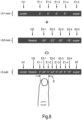
- Fig.8 shows a sketch of an already inventive thought process to achieve a particularly compact LED chain electronics LK-add.
- the LED chain electronics LK-1 and LK-2 are pulled apart slightly and the positions of the adjustment fields E2-1 to E2-5 of the LED chain electronics LK-2 are offset along the longitudinal extension L so that there is an imaginary combined, with respect to the adjustment fields E1-1 to E1-5 and E2-1 to E2-5 nested LED chain electronics LK-add results.
- the combined LED chain electronics LK-add has the same fields 101, 102, E1-1 to E1-4 and E2-1 to E2-4 as the LED chain electronics LK-1 and LK-2 and a combination of the LEDs -Chain electronics LK-1 and LK-2 identically designated setting fields E1-5 and E2-5 to a combination field KF.
- the setting fields E1-1 to E1-4 and E2-1 to E2-4 now alternate in the longitudinal direction.
- the combined LED chain electronics LK-add takes up noticeably less space than the two LED chain electronics LK-1 and LK-2.
- the setting fields E1-1 to E1-4 and E2-1 to E2-4 are now so close together that several of them are within the typical finger contact width B and therefore reliable operation according to the in Figures 6 and 7 described method is no longer available.
- the clarity is reduced due to the close and alternating position of the setting fields E1-1 to E1-4 and E2-1 to E2-4.
- Fig.1 shows a front view and thus also a top view of its operating surfaces, a sketch of a door 1 of a refrigerator 2 with an operating device arranged on the outside in the form of an LED chain electronics 3 according to a first exemplary embodiment.
- the LED chain electronics 3 have a user interface 4 and operating electronics 5 that are not visible to the user underneath.
- the backlit control panels SF1, SF2, E1-1 to E1-4, E2-1 to E2-4 and KF of the LED chain electronics 3 arranged in a row can largely correspond to the arrangement of the control panels of the LED chain electronics LK-add.
- the analogously positioned fields SF1 and SF2 are now touch-sensitive selection fields.
- the operating electronics 5 are set up for a different operation (eg programmed or wired) than in the case of the LED chain electronics LK-add.
- the LED chain electronics 3 here has two control lines BS-1 and BS-2, with the first control line BS-1 being assigned the control panels SF1, E1-1 to E1-4 and KF and the second control line BS-2 being assigned the SF2, E2-1 to E2-4 and KF are assigned.
- the two operating lines BS-1 and BS-2 thus differ in their selection fields SF1 and SF2 and in their exclusive setting fields E1-1 to E1-4 and E2-1 to E2-4. But they have one combo box KF in common.
- the setting fields E1-1 to E1-4 or E2-1 to E2-4 of the two operating lines are arranged alternately next to each other.
- the first control line BS-1 is provided for setting a target cooling temperature of a refrigerator compartment of the cooling device 2 and the second control line BS-2 with the control panels SF2, E2-1 to E2-4 and KF for setting a target cooling temperature of a freezer compartment .
- the control panels SF1, SF2, E1-1 to E1-4, E2-1 to E2-4 and KF are assigned respective physical touch fields 6, which are not visible to a user.
- Each of the control panels SF1, SF2, E1-1 to E1-4, E2-1 to E2-4 and KF is assigned a different optical mask through which the respective control panel SF1, SF2, E1-1 to E1-4, E2 -1 to E2-4 and KF light information about its function can be emitted.
- the touch fields 6 assigned to the selection fields SF1 and SF2 and the combination field KF along the longitudinal extension L are each as wide as the typical finger contact width B.
- the setting fields E1-1 to E1-4 and E2-1 to E2-4 are noticeably shorter.
- a distance dA between next-but-one adjacent setting fields E1-1 to E1-4 or E2-1 to E2-4 of the same operating line BS-1, BS-2 is equal to or greater than the typical finger contact width B, as shown here using setting fields E1 -1 and E1-3 shown.
- a distance dB between adjacent setting fields E1-1 to E1-4 or E2-1 to E2-4 of the same operating line BS-1, BS-2 is smaller than the typical finger contact width B, as shown here using the setting fields E2-1 and E2-2 shown.
- the associated setting fields E1-1 to E1-4 or E2-1 to E2-4 of the same operating line BS-1 or BS-2 are activated for selection by a user, while the setting fields E2- 1 to E2-4 or E1-1 to E1-4 of the respective other control line BS-2 or BS-1 can be deactivated, as explained in more detail below.
- the combination field KF belongs to both operating lines BS-1 and BS-2, it is or remains activated when both selection fields SF1, SF2 are actuated.
- Activations of the control panels SF1, SF2, E1-1 to E1-4, E2-1 to E2-4 and KF are recognized by means of the operating electronics 5.
- the operating electronics 5 are also set up to trigger at least one associated action if the associated control panel BS-1, BS-2 was selectable when operated by a user.
- Fig.2 shows a front view of a sketch of the LED chain electronics 3 in a first state, namely the waiting or standby state.
- the standby state is assumed, for example, when a user has not operated the LED chain electronics 3 for some time.
- the selection fields SF1 and SF2 are selectable for operation by a user and are dimly lit.
- the other control panels E1-1 to E1-4, E2-1 to E2-4 and KF are deactivated and therefore do not light up and cannot be actuated selectable. If a user presses on the non-user-selectable control panels E1-1 to E1-4, E2-1 to E2-4 and KF, the actuation is recognized by the operating electronics 5, but no associated or linked action is triggered.
- control panels that are not illuminated are not visible to a user compared to the background of the user interface 4 .
- the operating electronics 5 If a user presses his finger F on one of the selectable selection fields SF1 and SF2 (here for example on the selection field SF1, as indicated by the wide arrow), this is recognized by the operating electronics 5 . The operating electronics 5 then causes this selection field SF1 to be brightly backlit, as in Fig.3 shown. Since the other selection field SF2 remains user-selectable but is currently not selected, it remains dimly backlit. In particular, the state now exists in which the target temperature value in the cooling part can be set.
- the operating electronics 5 When the selection field SF1 is actuated, the operating electronics 5 also activate the control panels E1-1 to E1-4 and KF belonging to the same operating line BS-1, ie backlit and switched for selection by a user.
- the control panels E1-1, E1-3, E1-4 and KF are dimly backlit because the actions or functions/setting values linked to them are not currently set on cooling device 2.
- the setting field E1-2 is brightly backlit, since the setting value associated with it, namely the target temperature value of 4° C. in the cooling part, is currently set on the cooling device 2 .
- a user wants to change the target temperature value or effect rapid cooling, he can select one of the other control panels E1-1, E1-3, E1-4 or KF by actuation (touching, pressing, etc.).
- this control panel E1-1, E1-3, E1-4 or KF is switched on and the associated action (eg a change in the setpoint temperature value or a start of the rapid cooling) is triggered.
- the setting field E1-2 which was previously switched to being brightly lit, is switched to being dimly lit.
- the triggering of an action by the LED chain electronics 3 can include reporting a corresponding actuation to a central control device of the cooling device 2, which then changes over the cooling operation of the cooling part as an action.
- the other selection field SF2 is actuated within the specified period of time, it is brightly backlit, while the selection field SF1 is only weakly backlit, as in Fig.4 shown.
- the setting fields E1-1 to E1-4 assigned to the first operating line BS-1 are deactivated and the setting fields E1-1 to E1-4 assigned to the second operating line BS-2 are activated, the setting field E1-3 shining brightly here, for example, if the target temperature of the freezer compartment is currently set at -20°C.
- the combination field KF remains backlit. In particular, the state now exists in which the set temperature value in the freezer compartment can be set.
- non-selectable setting fields E-1 to E2-4 or E1-1 to E1-4 are not backlit, they do not appear optically either, so that the selectable setting fields E1-1 to E1-4 or E2 -1 to E2-4 are clearly arranged and are therefore easily distinguishable optically.
- Fig.5 shows a front view of a sketch of the door 2 of the refrigerator 1 with an LED chain electronics 7 according to a second embodiment of the invention instead of the LED chain electronics 3.
- the masks of the LED chain electronics 7 are arranged analogously to the masks of the LED chain electronics 3, and the associated control panels SF1, SF2, E1-1 to E1-4, E2-1 to E2-4 and KF are backlit as in the LED chain electronics 3.
- two adjacent setting fields E1-1, E2-1; E1-2, E2-2, etc. of different operating lines BS-1, BS-2 each have a common one Touch field 8 assigned. If one of the selection fields SF1 or SF2 is actuated, the control panels E1-1 to E1-4 or E2-1 to E2-4 assigned to the operating lines BS-1 or BS-2 light up, as in the case of the LED chain electronics 3 .
- the operating electronics 10 are set up to interpret the actuation of a touch field 8 as an actuation of the control panel E1-1 to E1-4 or E2-1 to E2-4 associated with the selected control line BS-1 or BS-2.
- both selection fields SF1 and SF2 have a common touch field 10 behind them. A user can toggle between these to select a desired selection field SF1 and SF2: for example, in the standby state, the lighting information “cooler” or “freezer” assigned to the selection fields SF1 and SF2 only lights up weakly.
- the selection field SF1 with the associated setting fields E1-1 to E1-4 and the combination field KF is activated for selection, analogously to the LED Chain electronics 3.
- the light information is also switched to "cooler” and brightly lit. The user can now select or activate the setting fields E1-1 to E1-4 and the combination field KF.
- the selection field SF2 with the associated setting fields E2-1 to E2-4 and the combination field KF is activated for selection, analogously to the LED chain electronics 3.
- the lighting information " freezer” is switched brightly lit, while the lighting information "cooler” is switched dimly lit.
- the user can now select or activate the setting fields E2-1 to E2-4 and the combination field KF.
- control line BS-1 is activated again, if it is pressed again, the control line BS-2 is activated again, etc.
- a user can then switch through or “toggle” between the selection fields one after the other by actuating the touch field several times.
- the currently selected selection field is indicated to a user by a brighter glow.
- several selection fields are provided as control panels that can be switched through one after the other.
- the invention can thus also be extended to three or more operating lines in an analogous manner.
- the number of setting fields for different operating lines can generally differ.
- the LED chain electronics can, for example, be attached horizontally or vertically to the household appliance. In the case of a vertical alignment, the light information is rotated by 90°, in contrast to the exemplary embodiments illustrated in the figures.
- toggleable selection fields as shown in the LED chain electronics 7 can be combined with setting fields as shown in the chain electronics 3 .
- "a”, “an” etc. can be understood as a singular or a plural number, in particular in the sense of “at least one” or “one or more” etc., as long as this is not explicitly excluded, e.g. by the expression “exactly a” etc.
- a numerical specification can also include exactly the specified number as well as a usual tolerance range, as long as this is not explicitly excluded.
Landscapes
- Engineering & Computer Science (AREA)
- General Engineering & Computer Science (AREA)
- Physics & Mathematics (AREA)
- Theoretical Computer Science (AREA)
- Chemical & Material Sciences (AREA)
- Combustion & Propulsion (AREA)
- Mechanical Engineering (AREA)
- Thermal Sciences (AREA)
- Human Computer Interaction (AREA)
- General Physics & Mathematics (AREA)
- Devices That Are Associated With Refrigeration Equipment (AREA)
- Cold Air Circulating Systems And Constructional Details In Refrigerators (AREA)
Claims (10)
- Dispositif électronique de chaîne de DEL (3, 7) pour un appareil électroménager (2), comprenant plusieurs champs de commande (SF1, SF2, E1-1 - E1-4, E2-1 - E2-4, KF) tactiles, disposés en rangée, dans lequel :- les champs de commande (SF1, SF2, E1-1 - E1-4, E2-1 - E2-4, KF) comprennent au moins deux zones de sélection (SF1, SF2), et lorsqu'elles sont actionnées, des champs de commande appartenant à la même ligne de commande (BS-1, BS-2) sous forme de champs de réglage (E1-1 - E1-4, E2-1 - E2-4) sont uniquement sélectionnables par un utilisateur,- les champs de réglage (E1-1 - E1-4, E2-1 - E2-4) de différentes lignes de commande (BS-1, BS-2) sont agencés alternativement l'un à côté de l'autre,- des champs de réglage (E1-1 - E1-4, E2-1 - E2-4) non sélectionnables par un utilisateur sont plus faiblement éclairés que des champs de réglage (E1-1 - E1-4, E2-1 - E2-4) sélectionnables par un utilisateur, mais non sélectionnés- des champs de réglage (E1-1 - E1-4, E2-1 - E2-4) sélectionnables par un utilisateur mais non sélectionnés sont plus faiblement éclairés que des champs de réglage (E1-2 - E2-3) sélectionnés par un utilisateur,- un intervalle (dA) entre des champs de réglage (E1-1 - E1-4, E2-1 - E2-4) avoisinants se suivant en seconde position de la même ligne de commande (BS-1, BS-2) est égal ou supérieur à une largeur de contact de doigt type (B) et un intervalle (dB) entre des champs de réglage (E1-1 - E1-4, E2-1 - E2-4) voisins de la même ligne de commande (BS-1, BS-2) est inférieur à la largeur de contact de doigt type (B), la largeur de contact de doigt type (B) étant entre 15 mm et 20 mm,- un champ tactile (6) respectif est associé à chaque champ de commande (SF1, SF2, E1-1 à E1-4, E2-1 à E2-4, et KF) ou le même champ tactile (8) est associé à des champs de réglage (E1-1, E2-1 ; E1-2, E2-2) voisins de différentes lignes de commande (BS-1, BS-2), et- le même champ tactile (10) est associé à plusieurs zones de sélection (SF1, SF2) et au moins une des zones de sélection (SF1, SF2) peut être sélectionnée par un actionnement multiple du champ tactile (10).
- Dispositif électronique de chaîne de DEL (3, 7) selon l'une des revendications précédentes, dans lequel au moins une largeur de contact de doigt type (B) est affectée respectivement aux zones de sélection (SF1, SF2) indépendamment de la sélection.
- Dispositif électronique de chaîne de DEL (3, 7) selon l'une des revendications précédentes, dans lequel les champs de réglage (E1-1 - E1-4, E2-1 - E2-4) d'au moins une même ligne de commande (BS-1, BS-2) sont configurés pour sélectionner différentes valeurs d'un paramètre de fonctionnement déterminé.
- Dispositif électronique de chaîne de DEL (3, 7) selon l'une des revendications précédentes, dans lequel le dispositif électronique de chaîne de DEL (3) comprend en outre au moins un champ de commande (SF1, SF2, E1-1 - E1-4, E2-1 - E2-4, KF) sous forme d'un champ combiné (KF), qui est sélectionnable par un utilisateur pour plusieurs lignes de commande sélectionnées (BS-1, BS-2).
- Dispositif électronique de chaîne de DEL (3, 7) selon l'une des revendications précédentes, dans lequel des champs de commande (E1-1 - E1-4, E2-1 - E2-4, KF) non sélectionnables par un utilisateur ne sont pas éclairés.
- Dispositif électronique de chaîne de DEL (7) selon l'une des revendications précédentes, dans lequel le même champ tactile (8) est affecté à des champs de réglage (E1-1 - E1-4, E2-1 - E2-4) voisins de différentes lignes de commande (BS-1, BS-2).
- Appareil électroménager (2), en particulier appareil frigorifique, comprenant au moins un dispositif électronique de chaîne de DEL (3) selon l'une des revendications précédentes.
- Appareil électroménager (2) selon la revendication 7 comprenant un dispositif électronique de chaîne de DEL (3) selon la revendication 6, dans lequel l'appareil électroménager (2) est un appareil frigorifique et les paramètres de fonctionnement associés aux lignes de commande (BS-1, BS-2) comprennent une température dans un compartiment de réfrigération et une température dans un compartiment de congélation d'un appareil frigorifique.
- Appareil électroménager (2) selon l'une des revendications 7 ou 8, dans lequel le dispositif électronique de chaîne de DEL (3, 7) est disposé sur une porte (1) de l'appareil électroménager (2).
- Procédé de fonctionnement d'un dispositif électronique de chaîne de LED (3) selon l'une des revendications 1 à 6, dans lequel :- les champs de commande (SF1, SF2, E1-1 - E1-4, E2-1 - E2-4, KF) sont surveillés quant à leur actionnement,- dans le cas où une sélection d'une zone de sélection (SF-1, SF-2) est détectée, les champs de réglage (E1-1 - E1-4, E2-1 - E2-4) correspondants sont activés et éclairés pour une sélection et les autres champs de réglage (E1-1 - E1-4, E2-1 - E2-4) sont désactivés et commutés en foncé, et- dans le cas où un actionnement d'un champ de réglage (E1-1 - E1-4, E2-1 - E2-4) actif est détecté, celui-ci est réglé en brillant et une action associée à ce champ de réglage (E1-1 - E1-4, E2-1 - E2-4) est déclenchée.
Applications Claiming Priority (1)
| Application Number | Priority Date | Filing Date | Title |
|---|---|---|---|
| DE102019212466.6A DE102019212466A1 (de) | 2019-08-21 | 2019-08-21 | LED-Kettenelektronik für ein Haushaltsgerät, Haushaltsgerät und Verfahren |
Publications (2)
| Publication Number | Publication Date |
|---|---|
| EP3783290A1 EP3783290A1 (fr) | 2021-02-24 |
| EP3783290B1 true EP3783290B1 (fr) | 2023-07-05 |
Family
ID=71741593
Family Applications (1)
| Application Number | Title | Priority Date | Filing Date |
|---|---|---|---|
| EP20186975.7A Active EP3783290B1 (fr) | 2019-08-21 | 2020-07-21 | Électronique de chaîne à led pour un appareil électroménager, appareil électroménager et procédé |
Country Status (2)
| Country | Link |
|---|---|
| EP (1) | EP3783290B1 (fr) |
| DE (1) | DE102019212466A1 (fr) |
Family Cites Families (5)
| Publication number | Priority date | Publication date | Assignee | Title |
|---|---|---|---|---|
| CN102418947B (zh) * | 2006-07-27 | 2014-06-18 | 松下电器产业株式会社 | 加热烹调器 |
| EP2392859B1 (fr) * | 2010-05-05 | 2017-03-29 | Electrolux Home Products Corporation N.V. | Interface de table de cuisson, panneau de table de cuisson, dispositif de cuisson et procédé de fonctionnement d'une interface de table de cuisson |
| DE102010062485B3 (de) * | 2010-12-06 | 2012-04-26 | E.G.O. Elektro-Gerätebau GmbH | Verfahren zur Steuerung eines Gerätes und Bedieneinrichtung dafür |
| EP3369179A1 (fr) * | 2015-10-30 | 2018-09-05 | Diehl AKO Stiftung & Co. KG | Commutateur tactile capacitif |
| DE102016223848A1 (de) * | 2016-11-30 | 2018-05-30 | E.G.O. Elektro-Gerätebau GmbH | Kochfeld und Verfahren zum Betrieb eines solchen Kochfeldes |
-
2019
- 2019-08-21 DE DE102019212466.6A patent/DE102019212466A1/de not_active Withdrawn
-
2020
- 2020-07-21 EP EP20186975.7A patent/EP3783290B1/fr active Active
Also Published As
| Publication number | Publication date |
|---|---|
| EP3783290A1 (fr) | 2021-02-24 |
| DE102019212466A1 (de) | 2021-02-25 |
Similar Documents
| Publication | Publication Date | Title |
|---|---|---|
| EP1257152B1 (fr) | Dispositif à interrupteur à effleurement et procédé de commande de l'interrupteur à effleurement | |
| EP2282126B1 (fr) | Hotte aspirante dotée d'une unité de commande | |
| EP1272007A2 (fr) | Commande de plaque de cuisson | |
| DE102011088483A1 (de) | Haushaltsgerät und Verfahren | |
| WO2007036247A1 (fr) | Procede pour commander et/ou evaluer un element de detection allonge d'un dispositif de commande, et dispositif de commande correspondant | |
| WO2014170161A1 (fr) | Table de cuisson comprenant une zone de cuisson et un symbole réduit dans la zone de cuisson dans une unité d'affichage, ainsi que procédé servant à faire fonctionner une table de cuisson | |
| EP2065650B1 (fr) | Appareil ménager doté d'une interface utilisateur comprenant un élément de réglage | |
| DE102005027199A1 (de) | Hausgerätevorrichtung mit wenigstens einem berührungsempfindlichen Sensorfeld | |
| DE102008026527A1 (de) | Verfahren zum Betreiben eines Haushaltsgeräts und Haushaltsgerät | |
| EP2751490B1 (fr) | Appareil ménager à élément de commande et procédé de fonctionnement d'un appareil ménager | |
| DE10211047B4 (de) | Anordnung zur Steuerung eines Kochfeldes | |
| EP0859193B1 (fr) | Tableau d'affichage et de commande pour une cuisinière, en particulier pour un four ménager | |
| DE102008032449A1 (de) | Anzeigeverfahren und Gargerät hierfür | |
| EP3783290B1 (fr) | Électronique de chaîne à led pour un appareil électroménager, appareil électroménager et procédé | |
| DE102019006628A1 (de) | Bedienvorrichtung | |
| EP1907760B1 (fr) | Appareil menager, en particulier appareil de cuisson a ligne de reglage tactile | |
| EP3330617A1 (fr) | Plaque de cuisson et procédé de fonctionnement d'une telle plaque de cuisson | |
| EP3974730B1 (fr) | Système comprenant une plaque de cuisson, une hotte aspirante doté d'un éclairage et d'une commande d'éclairage, et procédé de fonctionnement d'un tel système | |
| EP2603739B1 (fr) | Appareil électroménager présentant une plaque de cuisson et procédé d'affichage de la consommation d'énergie | |
| DE102011006274B3 (de) | Steuergerät für ein Kochfeld mit mehreren Kochstellen und zugehöriges Betriebsverfahren | |
| EP1486733B1 (fr) | appareil de four cuisiniere | |
| DE102008032452A1 (de) | Anzeigeverfahren und Gargerät hierfür | |
| EP3579415B1 (fr) | Procédé de commande d'un appareil de cuisson électrique et appareil de cuisson électrique | |
| BE1030351B1 (de) | Haushaltsgerät, vorzugsweise Küchengerät, besonders vorzugsweise Kochfeld | |
| DE102009028220A1 (de) | Dunstabzugshaube und Verfahren zur Steuerung einer Dunstabzugshaube |
Legal Events
| Date | Code | Title | Description |
|---|---|---|---|
| PUAI | Public reference made under article 153(3) epc to a published international application that has entered the european phase |
Free format text: ORIGINAL CODE: 0009012 |
|
| STAA | Information on the status of an ep patent application or granted ep patent |
Free format text: STATUS: THE APPLICATION HAS BEEN PUBLISHED |
|
| AK | Designated contracting states |
Kind code of ref document: A1 Designated state(s): AL AT BE BG CH CY CZ DE DK EE ES FI FR GB GR HR HU IE IS IT LI LT LU LV MC MK MT NL NO PL PT RO RS SE SI SK SM TR |
|
| AX | Request for extension of the european patent |
Extension state: BA ME |
|
| STAA | Information on the status of an ep patent application or granted ep patent |
Free format text: STATUS: REQUEST FOR EXAMINATION WAS MADE |
|
| 17P | Request for examination filed |
Effective date: 20210824 |
|
| RBV | Designated contracting states (corrected) |
Designated state(s): AL AT BE BG CH CY CZ DE DK EE ES FI FR GB GR HR HU IE IS IT LI LT LU LV MC MK MT NL NO PL PT RO RS SE SI SK SM TR |
|
| GRAP | Despatch of communication of intention to grant a patent |
Free format text: ORIGINAL CODE: EPIDOSNIGR1 |
|
| STAA | Information on the status of an ep patent application or granted ep patent |
Free format text: STATUS: GRANT OF PATENT IS INTENDED |
|
| RIC1 | Information provided on ipc code assigned before grant |
Ipc: G06F 3/01 20060101ALI20230124BHEP Ipc: F25D 29/00 20060101AFI20230124BHEP |
|
| INTG | Intention to grant announced |
Effective date: 20230223 |
|
| GRAS | Grant fee paid |
Free format text: ORIGINAL CODE: EPIDOSNIGR3 |
|
| GRAA | (expected) grant |
Free format text: ORIGINAL CODE: 0009210 |
|
| STAA | Information on the status of an ep patent application or granted ep patent |
Free format text: STATUS: THE PATENT HAS BEEN GRANTED |
|
| AK | Designated contracting states |
Kind code of ref document: B1 Designated state(s): AL AT BE BG CH CY CZ DE DK EE ES FI FR GB GR HR HU IE IS IT LI LT LU LV MC MK MT NL NO PL PT RO RS SE SI SK SM TR |
|
| REG | Reference to a national code |
Ref country code: CH Ref legal event code: EP |
|
| REG | Reference to a national code |
Ref country code: AT Ref legal event code: REF Ref document number: 1585182 Country of ref document: AT Kind code of ref document: T Effective date: 20230715 |
|
| REG | Reference to a national code |
Ref country code: DE Ref legal event code: R096 Ref document number: 502020004011 Country of ref document: DE |
|
| REG | Reference to a national code |
Ref country code: IE Ref legal event code: FG4D Free format text: LANGUAGE OF EP DOCUMENT: GERMAN |
|
| REG | Reference to a national code |
Ref country code: LT Ref legal event code: MG9D |
|
| REG | Reference to a national code |
Ref country code: NL Ref legal event code: MP Effective date: 20230705 |
|
| PGFP | Annual fee paid to national office [announced via postgrant information from national office to epo] |
Ref country code: DE Payment date: 20230731 Year of fee payment: 4 |
|
| PG25 | Lapsed in a contracting state [announced via postgrant information from national office to epo] |
Ref country code: NL Free format text: LAPSE BECAUSE OF FAILURE TO SUBMIT A TRANSLATION OF THE DESCRIPTION OR TO PAY THE FEE WITHIN THE PRESCRIBED TIME-LIMIT Effective date: 20230705 |
|
| PG25 | Lapsed in a contracting state [announced via postgrant information from national office to epo] |
Ref country code: GR Free format text: LAPSE BECAUSE OF FAILURE TO SUBMIT A TRANSLATION OF THE DESCRIPTION OR TO PAY THE FEE WITHIN THE PRESCRIBED TIME-LIMIT Effective date: 20231006 |
|
| PG25 | Lapsed in a contracting state [announced via postgrant information from national office to epo] |
Ref country code: ES Free format text: LAPSE BECAUSE OF FAILURE TO SUBMIT A TRANSLATION OF THE DESCRIPTION OR TO PAY THE FEE WITHIN THE PRESCRIBED TIME-LIMIT Effective date: 20230705 |
|
| PG25 | Lapsed in a contracting state [announced via postgrant information from national office to epo] |
Ref country code: IS Free format text: LAPSE BECAUSE OF FAILURE TO SUBMIT A TRANSLATION OF THE DESCRIPTION OR TO PAY THE FEE WITHIN THE PRESCRIBED TIME-LIMIT Effective date: 20231105 |
|
| PG25 | Lapsed in a contracting state [announced via postgrant information from national office to epo] |
Ref country code: SE Free format text: LAPSE BECAUSE OF FAILURE TO SUBMIT A TRANSLATION OF THE DESCRIPTION OR TO PAY THE FEE WITHIN THE PRESCRIBED TIME-LIMIT Effective date: 20230705 Ref country code: RS Free format text: LAPSE BECAUSE OF FAILURE TO SUBMIT A TRANSLATION OF THE DESCRIPTION OR TO PAY THE FEE WITHIN THE PRESCRIBED TIME-LIMIT Effective date: 20230705 Ref country code: PT Free format text: LAPSE BECAUSE OF FAILURE TO SUBMIT A TRANSLATION OF THE DESCRIPTION OR TO PAY THE FEE WITHIN THE PRESCRIBED TIME-LIMIT Effective date: 20231106 Ref country code: NO Free format text: LAPSE BECAUSE OF FAILURE TO SUBMIT A TRANSLATION OF THE DESCRIPTION OR TO PAY THE FEE WITHIN THE PRESCRIBED TIME-LIMIT Effective date: 20231005 Ref country code: LV Free format text: LAPSE BECAUSE OF FAILURE TO SUBMIT A TRANSLATION OF THE DESCRIPTION OR TO PAY THE FEE WITHIN THE PRESCRIBED TIME-LIMIT Effective date: 20230705 Ref country code: LT Free format text: LAPSE BECAUSE OF FAILURE TO SUBMIT A TRANSLATION OF THE DESCRIPTION OR TO PAY THE FEE WITHIN THE PRESCRIBED TIME-LIMIT Effective date: 20230705 Ref country code: IS Free format text: LAPSE BECAUSE OF FAILURE TO SUBMIT A TRANSLATION OF THE DESCRIPTION OR TO PAY THE FEE WITHIN THE PRESCRIBED TIME-LIMIT Effective date: 20231105 Ref country code: HR Free format text: LAPSE BECAUSE OF FAILURE TO SUBMIT A TRANSLATION OF THE DESCRIPTION OR TO PAY THE FEE WITHIN THE PRESCRIBED TIME-LIMIT Effective date: 20230705 Ref country code: GR Free format text: LAPSE BECAUSE OF FAILURE TO SUBMIT A TRANSLATION OF THE DESCRIPTION OR TO PAY THE FEE WITHIN THE PRESCRIBED TIME-LIMIT Effective date: 20231006 Ref country code: FI Free format text: LAPSE BECAUSE OF FAILURE TO SUBMIT A TRANSLATION OF THE DESCRIPTION OR TO PAY THE FEE WITHIN THE PRESCRIBED TIME-LIMIT Effective date: 20230705 Ref country code: ES Free format text: LAPSE BECAUSE OF FAILURE TO SUBMIT A TRANSLATION OF THE DESCRIPTION OR TO PAY THE FEE WITHIN THE PRESCRIBED TIME-LIMIT Effective date: 20230705 |
|
| PG25 | Lapsed in a contracting state [announced via postgrant information from national office to epo] |
Ref country code: PL Free format text: LAPSE BECAUSE OF FAILURE TO SUBMIT A TRANSLATION OF THE DESCRIPTION OR TO PAY THE FEE WITHIN THE PRESCRIBED TIME-LIMIT Effective date: 20230705 |
|
| REG | Reference to a national code |
Ref country code: CH Ref legal event code: PL |
|
| REG | Reference to a national code |
Ref country code: BE Ref legal event code: MM Effective date: 20230731 |
|
| PG25 | Lapsed in a contracting state [announced via postgrant information from national office to epo] |
Ref country code: LU Free format text: LAPSE BECAUSE OF NON-PAYMENT OF DUE FEES Effective date: 20230721 |
|
| PG25 | Lapsed in a contracting state [announced via postgrant information from national office to epo] |
Ref country code: LU Free format text: LAPSE BECAUSE OF NON-PAYMENT OF DUE FEES Effective date: 20230721 |
|
| REG | Reference to a national code |
Ref country code: DE Ref legal event code: R097 Ref document number: 502020004011 Country of ref document: DE |
|
| REG | Reference to a national code |
Ref country code: IE Ref legal event code: MM4A |
|
| PG25 | Lapsed in a contracting state [announced via postgrant information from national office to epo] |
Ref country code: SM Free format text: LAPSE BECAUSE OF FAILURE TO SUBMIT A TRANSLATION OF THE DESCRIPTION OR TO PAY THE FEE WITHIN THE PRESCRIBED TIME-LIMIT Effective date: 20230705 Ref country code: RO Free format text: LAPSE BECAUSE OF FAILURE TO SUBMIT A TRANSLATION OF THE DESCRIPTION OR TO PAY THE FEE WITHIN THE PRESCRIBED TIME-LIMIT Effective date: 20230705 Ref country code: EE Free format text: LAPSE BECAUSE OF FAILURE TO SUBMIT A TRANSLATION OF THE DESCRIPTION OR TO PAY THE FEE WITHIN THE PRESCRIBED TIME-LIMIT Effective date: 20230705 Ref country code: DK Free format text: LAPSE BECAUSE OF FAILURE TO SUBMIT A TRANSLATION OF THE DESCRIPTION OR TO PAY THE FEE WITHIN THE PRESCRIBED TIME-LIMIT Effective date: 20230705 Ref country code: CZ Free format text: LAPSE BECAUSE OF FAILURE TO SUBMIT A TRANSLATION OF THE DESCRIPTION OR TO PAY THE FEE WITHIN THE PRESCRIBED TIME-LIMIT Effective date: 20230705 Ref country code: SK Free format text: LAPSE BECAUSE OF FAILURE TO SUBMIT A TRANSLATION OF THE DESCRIPTION OR TO PAY THE FEE WITHIN THE PRESCRIBED TIME-LIMIT Effective date: 20230705 Ref country code: CH Free format text: LAPSE BECAUSE OF NON-PAYMENT OF DUE FEES Effective date: 20230731 Ref country code: MC Free format text: LAPSE BECAUSE OF FAILURE TO SUBMIT A TRANSLATION OF THE DESCRIPTION OR TO PAY THE FEE WITHIN THE PRESCRIBED TIME-LIMIT Effective date: 20230705 |
|
| PLBE | No opposition filed within time limit |
Free format text: ORIGINAL CODE: 0009261 |
|
| STAA | Information on the status of an ep patent application or granted ep patent |
Free format text: STATUS: NO OPPOSITION FILED WITHIN TIME LIMIT |
|
| PG25 | Lapsed in a contracting state [announced via postgrant information from national office to epo] |
Ref country code: IT Free format text: LAPSE BECAUSE OF FAILURE TO SUBMIT A TRANSLATION OF THE DESCRIPTION OR TO PAY THE FEE WITHIN THE PRESCRIBED TIME-LIMIT Effective date: 20230705 Ref country code: BE Free format text: LAPSE BECAUSE OF NON-PAYMENT OF DUE FEES Effective date: 20230731 |
|
| 26N | No opposition filed |
Effective date: 20240408 |
|
| PG25 | Lapsed in a contracting state [announced via postgrant information from national office to epo] |
Ref country code: IE Free format text: LAPSE BECAUSE OF NON-PAYMENT OF DUE FEES Effective date: 20230721 |
|
| PG25 | Lapsed in a contracting state [announced via postgrant information from national office to epo] |
Ref country code: IE Free format text: LAPSE BECAUSE OF NON-PAYMENT OF DUE FEES Effective date: 20230721 Ref country code: FR Free format text: LAPSE BECAUSE OF NON-PAYMENT OF DUE FEES Effective date: 20230905 Ref country code: SI Free format text: LAPSE BECAUSE OF FAILURE TO SUBMIT A TRANSLATION OF THE DESCRIPTION OR TO PAY THE FEE WITHIN THE PRESCRIBED TIME-LIMIT Effective date: 20230705 |
|
| PG25 | Lapsed in a contracting state [announced via postgrant information from national office to epo] |
Ref country code: BG Free format text: LAPSE BECAUSE OF FAILURE TO SUBMIT A TRANSLATION OF THE DESCRIPTION OR TO PAY THE FEE WITHIN THE PRESCRIBED TIME-LIMIT Effective date: 20230705 |
|
| PG25 | Lapsed in a contracting state [announced via postgrant information from national office to epo] |
Ref country code: BG Free format text: LAPSE BECAUSE OF FAILURE TO SUBMIT A TRANSLATION OF THE DESCRIPTION OR TO PAY THE FEE WITHIN THE PRESCRIBED TIME-LIMIT Effective date: 20230705 |
|
| REG | Reference to a national code |
Ref country code: DE Ref legal event code: R119 Ref document number: 502020004011 Country of ref document: DE |
|
| GBPC | Gb: european patent ceased through non-payment of renewal fee |
Effective date: 20240721 |
|
| PG25 | Lapsed in a contracting state [announced via postgrant information from national office to epo] |
Ref country code: DE Free format text: LAPSE BECAUSE OF NON-PAYMENT OF DUE FEES Effective date: 20250201 |
|
| PG25 | Lapsed in a contracting state [announced via postgrant information from national office to epo] |
Ref country code: GB Free format text: LAPSE BECAUSE OF NON-PAYMENT OF DUE FEES Effective date: 20240721 |
|
| PG25 | Lapsed in a contracting state [announced via postgrant information from national office to epo] |
Ref country code: CY Free format text: LAPSE BECAUSE OF FAILURE TO SUBMIT A TRANSLATION OF THE DESCRIPTION OR TO PAY THE FEE WITHIN THE PRESCRIBED TIME-LIMIT; INVALID AB INITIO Effective date: 20200721 |
|
| PG25 | Lapsed in a contracting state [announced via postgrant information from national office to epo] |
Ref country code: HU Free format text: LAPSE BECAUSE OF FAILURE TO SUBMIT A TRANSLATION OF THE DESCRIPTION OR TO PAY THE FEE WITHIN THE PRESCRIBED TIME-LIMIT; INVALID AB INITIO Effective date: 20200721 |
|
| PGFP | Annual fee paid to national office [announced via postgrant information from national office to epo] |
Ref country code: AT Payment date: 20251020 Year of fee payment: 5 |
|
| PG25 | Lapsed in a contracting state [announced via postgrant information from national office to epo] |
Ref country code: TR Free format text: LAPSE BECAUSE OF FAILURE TO SUBMIT A TRANSLATION OF THE DESCRIPTION OR TO PAY THE FEE WITHIN THE PRESCRIBED TIME-LIMIT Effective date: 20230705 |