EP3783319A2 - Débitmètre - Google Patents
Débitmètre Download PDFInfo
- Publication number
- EP3783319A2 EP3783319A2 EP20190435.6A EP20190435A EP3783319A2 EP 3783319 A2 EP3783319 A2 EP 3783319A2 EP 20190435 A EP20190435 A EP 20190435A EP 3783319 A2 EP3783319 A2 EP 3783319A2
- Authority
- EP
- European Patent Office
- Prior art keywords
- magnetic field
- rotating structure
- processing circuit
- rotating
- flow meter
- Prior art date
- Legal status (The legal status is an assumption and is not a legal conclusion. Google has not performed a legal analysis and makes no representation as to the accuracy of the status listed.)
- Granted
Links
Images



Classifications
-
- G—PHYSICS
- G01—MEASURING; TESTING
- G01F—MEASURING VOLUME, VOLUME FLOW, MASS FLOW OR LIQUID LEVEL; METERING BY VOLUME
- G01F1/00—Measuring the volume flow or mass flow of fluid or fluent solid material wherein the fluid passes through a meter in a continuous flow
- G01F1/05—Measuring the volume flow or mass flow of fluid or fluent solid material wherein the fluid passes through a meter in a continuous flow by using mechanical effects
- G01F1/10—Measuring the volume flow or mass flow of fluid or fluent solid material wherein the fluid passes through a meter in a continuous flow by using mechanical effects using rotating vanes with axial admission
- G01F1/115—Measuring the volume flow or mass flow of fluid or fluent solid material wherein the fluid passes through a meter in a continuous flow by using mechanical effects using rotating vanes with axial admission with magnetic or electromagnetic coupling to the indicating device
- G01F1/1155—Measuring the volume flow or mass flow of fluid or fluent solid material wherein the fluid passes through a meter in a continuous flow by using mechanical effects using rotating vanes with axial admission with magnetic or electromagnetic coupling to the indicating device with magnetic coupling only in a mechanical transmission path
-
- G—PHYSICS
- G01—MEASURING; TESTING
- G01F—MEASURING VOLUME, VOLUME FLOW, MASS FLOW OR LIQUID LEVEL; METERING BY VOLUME
- G01F1/00—Measuring the volume flow or mass flow of fluid or fluent solid material wherein the fluid passes through a meter in a continuous flow
- G01F1/05—Measuring the volume flow or mass flow of fluid or fluent solid material wherein the fluid passes through a meter in a continuous flow by using mechanical effects
-
- G—PHYSICS
- G01—MEASURING; TESTING
- G01F—MEASURING VOLUME, VOLUME FLOW, MASS FLOW OR LIQUID LEVEL; METERING BY VOLUME
- G01F3/00—Measuring the volume flow of fluids or fluent solid material wherein the fluid passes through the meter in successive and more or less isolated quantities, the meter being driven by the flow
- G01F3/02—Measuring the volume flow of fluids or fluent solid material wherein the fluid passes through the meter in successive and more or less isolated quantities, the meter being driven by the flow with measuring chambers which expand or contract during measurement
- G01F3/04—Measuring the volume flow of fluids or fluent solid material wherein the fluid passes through the meter in successive and more or less isolated quantities, the meter being driven by the flow with measuring chambers which expand or contract during measurement having rigid movable walls
- G01F3/06—Measuring the volume flow of fluids or fluent solid material wherein the fluid passes through the meter in successive and more or less isolated quantities, the meter being driven by the flow with measuring chambers which expand or contract during measurement having rigid movable walls comprising members rotating in a fluid-tight or substantially fluid-tight manner in a housing
- G01F3/10—Geared or lobed impeller meters
-
- G—PHYSICS
- G01—MEASURING; TESTING
- G01D—MEASURING NOT SPECIALLY ADAPTED FOR A SPECIFIC VARIABLE; ARRANGEMENTS FOR MEASURING TWO OR MORE VARIABLES NOT COVERED IN A SINGLE OTHER SUBCLASS; TARIFF METERING APPARATUS; MEASURING OR TESTING NOT OTHERWISE PROVIDED FOR
- G01D5/00—Mechanical means for transferring the output of a sensing member; Means for converting the output of a sensing member to another variable where the form or nature of the sensing member does not constrain the means for converting; Transducers not specially adapted for a specific variable
- G01D5/12—Mechanical means for transferring the output of a sensing member; Means for converting the output of a sensing member to another variable where the form or nature of the sensing member does not constrain the means for converting; Transducers not specially adapted for a specific variable using electric or magnetic means
- G01D5/14—Mechanical means for transferring the output of a sensing member; Means for converting the output of a sensing member to another variable where the form or nature of the sensing member does not constrain the means for converting; Transducers not specially adapted for a specific variable using electric or magnetic means influencing the magnitude of a current or voltage
-
- G—PHYSICS
- G01—MEASURING; TESTING
- G01D—MEASURING NOT SPECIALLY ADAPTED FOR A SPECIFIC VARIABLE; ARRANGEMENTS FOR MEASURING TWO OR MORE VARIABLES NOT COVERED IN A SINGLE OTHER SUBCLASS; TARIFF METERING APPARATUS; MEASURING OR TESTING NOT OTHERWISE PROVIDED FOR
- G01D5/00—Mechanical means for transferring the output of a sensing member; Means for converting the output of a sensing member to another variable where the form or nature of the sensing member does not constrain the means for converting; Transducers not specially adapted for a specific variable
- G01D5/12—Mechanical means for transferring the output of a sensing member; Means for converting the output of a sensing member to another variable where the form or nature of the sensing member does not constrain the means for converting; Transducers not specially adapted for a specific variable using electric or magnetic means
- G01D5/244—Mechanical means for transferring the output of a sensing member; Means for converting the output of a sensing member to another variable where the form or nature of the sensing member does not constrain the means for converting; Transducers not specially adapted for a specific variable using electric or magnetic means influencing characteristics of pulses or pulse trains; generating pulses or pulse trains
-
- G—PHYSICS
- G01—MEASURING; TESTING
- G01F—MEASURING VOLUME, VOLUME FLOW, MASS FLOW OR LIQUID LEVEL; METERING BY VOLUME
- G01F1/00—Measuring the volume flow or mass flow of fluid or fluent solid material wherein the fluid passes through a meter in a continuous flow
- G01F1/05—Measuring the volume flow or mass flow of fluid or fluent solid material wherein the fluid passes through a meter in a continuous flow by using mechanical effects
- G01F1/06—Measuring the volume flow or mass flow of fluid or fluent solid material wherein the fluid passes through a meter in a continuous flow by using mechanical effects using rotating vanes with tangential admission
- G01F1/075—Measuring the volume flow or mass flow of fluid or fluent solid material wherein the fluid passes through a meter in a continuous flow by using mechanical effects using rotating vanes with tangential admission with magnetic or electromagnetic coupling to the indicating device
-
- G—PHYSICS
- G01—MEASURING; TESTING
- G01F—MEASURING VOLUME, VOLUME FLOW, MASS FLOW OR LIQUID LEVEL; METERING BY VOLUME
- G01F1/00—Measuring the volume flow or mass flow of fluid or fluent solid material wherein the fluid passes through a meter in a continuous flow
- G01F1/05—Measuring the volume flow or mass flow of fluid or fluent solid material wherein the fluid passes through a meter in a continuous flow by using mechanical effects
- G01F1/06—Measuring the volume flow or mass flow of fluid or fluent solid material wherein the fluid passes through a meter in a continuous flow by using mechanical effects using rotating vanes with tangential admission
- G01F1/075—Measuring the volume flow or mass flow of fluid or fluent solid material wherein the fluid passes through a meter in a continuous flow by using mechanical effects using rotating vanes with tangential admission with magnetic or electromagnetic coupling to the indicating device
- G01F1/0755—Measuring the volume flow or mass flow of fluid or fluent solid material wherein the fluid passes through a meter in a continuous flow by using mechanical effects using rotating vanes with tangential admission with magnetic or electromagnetic coupling to the indicating device with magnetic coupling only in a mechanical transmission path
-
- G—PHYSICS
- G01—MEASURING; TESTING
- G01F—MEASURING VOLUME, VOLUME FLOW, MASS FLOW OR LIQUID LEVEL; METERING BY VOLUME
- G01F1/00—Measuring the volume flow or mass flow of fluid or fluent solid material wherein the fluid passes through a meter in a continuous flow
- G01F1/05—Measuring the volume flow or mass flow of fluid or fluent solid material wherein the fluid passes through a meter in a continuous flow by using mechanical effects
- G01F1/06—Measuring the volume flow or mass flow of fluid or fluent solid material wherein the fluid passes through a meter in a continuous flow by using mechanical effects using rotating vanes with tangential admission
- G01F1/08—Adjusting, correcting or compensating means therefor
-
- G—PHYSICS
- G01—MEASURING; TESTING
- G01F—MEASURING VOLUME, VOLUME FLOW, MASS FLOW OR LIQUID LEVEL; METERING BY VOLUME
- G01F1/00—Measuring the volume flow or mass flow of fluid or fluent solid material wherein the fluid passes through a meter in a continuous flow
- G01F1/05—Measuring the volume flow or mass flow of fluid or fluent solid material wherein the fluid passes through a meter in a continuous flow by using mechanical effects
- G01F1/10—Measuring the volume flow or mass flow of fluid or fluent solid material wherein the fluid passes through a meter in a continuous flow by using mechanical effects using rotating vanes with axial admission
- G01F1/115—Measuring the volume flow or mass flow of fluid or fluent solid material wherein the fluid passes through a meter in a continuous flow by using mechanical effects using rotating vanes with axial admission with magnetic or electromagnetic coupling to the indicating device
-
- G—PHYSICS
- G01—MEASURING; TESTING
- G01F—MEASURING VOLUME, VOLUME FLOW, MASS FLOW OR LIQUID LEVEL; METERING BY VOLUME
- G01F1/00—Measuring the volume flow or mass flow of fluid or fluent solid material wherein the fluid passes through a meter in a continuous flow
- G01F1/05—Measuring the volume flow or mass flow of fluid or fluent solid material wherein the fluid passes through a meter in a continuous flow by using mechanical effects
- G01F1/10—Measuring the volume flow or mass flow of fluid or fluent solid material wherein the fluid passes through a meter in a continuous flow by using mechanical effects using rotating vanes with axial admission
- G01F1/12—Adjusting, correcting, or compensating means therefor
- G01F1/125—Adjusting, correcting, or compensating means therefor with electric, electro-mechanical or electronic means
-
- G—PHYSICS
- G01—MEASURING; TESTING
- G01F—MEASURING VOLUME, VOLUME FLOW, MASS FLOW OR LIQUID LEVEL; METERING BY VOLUME
- G01F11/00—Apparatus requiring external operation adapted at each repeated and identical operation to measure and separate a predetermined volume of fluid or fluent solid material from a supply or container, without regard to weight, and to deliver it
- G01F11/28—Apparatus requiring external operation adapted at each repeated and identical operation to measure and separate a predetermined volume of fluid or fluent solid material from a supply or container, without regard to weight, and to deliver it with stationary measuring chambers having constant volume during measurement
-
- G—PHYSICS
- G01—MEASURING; TESTING
- G01F—MEASURING VOLUME, VOLUME FLOW, MASS FLOW OR LIQUID LEVEL; METERING BY VOLUME
- G01F25/00—Testing or calibration of apparatus for measuring volume, volume flow or liquid level or for metering by volume
- G01F25/10—Testing or calibration of apparatus for measuring volume, volume flow or liquid level or for metering by volume of flowmeters
-
- G—PHYSICS
- G01—MEASURING; TESTING
- G01P—MEASURING LINEAR OR ANGULAR SPEED, ACCELERATION, DECELERATION, OR SHOCK; INDICATING PRESENCE, ABSENCE, OR DIRECTION, OF MOVEMENT
- G01P3/00—Measuring linear or angular speed; Measuring differences of linear or angular speeds
- G01P3/42—Devices characterised by the use of electric or magnetic means
- G01P3/44—Devices characterised by the use of electric or magnetic means for measuring angular speed
- G01P3/48—Devices characterised by the use of electric or magnetic means for measuring angular speed by measuring frequency of generated current or voltage
-
- G—PHYSICS
- G01—MEASURING; TESTING
- G01P—MEASURING LINEAR OR ANGULAR SPEED, ACCELERATION, DECELERATION, OR SHOCK; INDICATING PRESENCE, ABSENCE, OR DIRECTION, OF MOVEMENT
- G01P3/00—Measuring linear or angular speed; Measuring differences of linear or angular speeds
- G01P3/42—Devices characterised by the use of electric or magnetic means
- G01P3/44—Devices characterised by the use of electric or magnetic means for measuring angular speed
- G01P3/48—Devices characterised by the use of electric or magnetic means for measuring angular speed by measuring frequency of generated current or voltage
- G01P3/481—Devices characterised by the use of electric or magnetic means for measuring angular speed by measuring frequency of generated current or voltage of pulse signals
- G01P3/487—Devices characterised by the use of electric or magnetic means for measuring angular speed by measuring frequency of generated current or voltage of pulse signals delivered by rotating magnets
-
- G—PHYSICS
- G01—MEASURING; TESTING
- G01F—MEASURING VOLUME, VOLUME FLOW, MASS FLOW OR LIQUID LEVEL; METERING BY VOLUME
- G01F15/00—Details of, or accessories for, apparatus of groups G01F1/00 - G01F13/00 insofar as such details or appliances are not adapted to particular types of such apparatus
- G01F15/007—Details of, or accessories for, apparatus of groups G01F1/00 - G01F13/00 insofar as such details or appliances are not adapted to particular types of such apparatus comprising means to prevent fraud
-
- G—PHYSICS
- G01—MEASURING; TESTING
- G01F—MEASURING VOLUME, VOLUME FLOW, MASS FLOW OR LIQUID LEVEL; METERING BY VOLUME
- G01F15/00—Details of, or accessories for, apparatus of groups G01F1/00 - G01F13/00 insofar as such details or appliances are not adapted to particular types of such apparatus
- G01F15/06—Indicating or recording devices
- G01F15/065—Indicating or recording devices with transmission devices, e.g. mechanical
- G01F15/066—Indicating or recording devices with transmission devices, e.g. mechanical involving magnetic transmission devices
-
- G—PHYSICS
- G01—MEASURING; TESTING
- G01F—MEASURING VOLUME, VOLUME FLOW, MASS FLOW OR LIQUID LEVEL; METERING BY VOLUME
- G01F15/00—Details of, or accessories for, apparatus of groups G01F1/00 - G01F13/00 insofar as such details or appliances are not adapted to particular types of such apparatus
- G01F15/06—Indicating or recording devices
- G01F15/068—Indicating or recording devices with electrical means
Definitions
- the present invention relates generally to a flow meter, and more particularly, to a flow meter with a rotating structure.
- the prior art provides various flow meters for fluids of different properties, including: ultrasonic flow meters, variable area flow meters, Coriolis flow meters, and paddle wheel flow meters, positive displacement flow meters, turbine flow meters, laminar flow meters, electromagnetic flow meters, thermal mass flow meters, and so on.
- the paddle wheel flow meter, the positive displacement flow meter, and the turbine flow meter include a rotating structure with magnetic elements, a sensor, and a processing circuit.
- the rotating structure is arranged in the pipeline and the sensor is kept a distance from the rotating structure, when the fluid drives the rotating structure, the magnetic field intensity around the magnetic element changes periodically, the sensor senses the change in the magnetic field intensity to generate a pulse sensing signal, and the processing circuit generates the flow measurement according to the pulsed sensing signal.
- the rotating structure In the aforementioned flow meter with a rotating structure, the rotating structure must rotate at least 60 to 180 degrees to generate a pulse sensing signal.
- the rotating structure has a low speed (i.e., low flow)
- the number of pulse sensing signals per unit time is too few and the processing circuit cannot generate reliable flow data; therefore, the actual measurement error of the conventional flow meter at low flow rates can reach more than 5 times.
- the processing circuit cannot judge the flow direction of the fluid from the pulse sensing signal, nor can it distinguish whether the cause of the change of magnetic field intensity is from fluid flow rate changes, rotating mechanism wear or external magnetic field interference, which affects the reliability of the flow data.
- the conventional flow meter with a rotating structure has problems such as restricted flow sensing range, inability to determine the flow direction and abnormality of the rotating structure, and inability to distinguish flow velocity changes from external magnetic field interference. How to solve the various problems of the prior art and improve the flow sensing range, accuracy and reliability of the flow meter with a rotating structure is the main objective of the development of the present invention.
- the present invention provides a flow meter including: a rotating structure, a sensing element and a processing circuit.
- the rotating structure has a shaft, a rotating element, and a magnetic element.
- the rotating element can be driven by a fluid in a pipeline to rotate around the shaft.
- the magnetic element is arranged on the rotating element with two magnetic poles parallel to a tangent line of rotating circle of the rotating element.
- the sensing element is separated from the rotating structure by a distance, and includes a first sensing unit and a second sensing unit, which respectively sense a magnetic field of the magnetic element in a first direction and a second direction to generate a first magnetic field component signal and a second magnetic field component signal.
- the processing circuit is connected to the sensing element, and generates an angle of the rotating structure according to the first magnetic field component signal and the second magnetic field component signal.
- the number of the rotating elements is plural, and each of the rotating elements is provided with the magnetic element.
- first direction and the second direction are perpendicular to each other.
- the processing circuit generates an angular velocity of the rotating structure by calculating an angular variation of the rotating structure at two time points, and generates a flow rate of the fluid based on the angular velocity of the rotating structure and cross-sectional area of the pipeline.
- the processing circuit determines the flow direction of the fluid according to the angular variation of the rotating structure.
- the flow meter further includes a display module connected to the processing circuit for displaying the flow rate of the fluid.
- the flow meter further includes: a communication module connected to the processing circuit, and transmitting the angle of the rotating structure to a monitoring device in a wired or wireless manner, wherein the monitoring device generates the angular velocity of the rotating structure by calculating the angular variation of the rotating structure at two time points, and generates the flow rate of the fluid based on the angular velocity of the rotating structure and cross-sectional area of the pipeline.
- the processing circuit further calculates magnetic field intensity according to the first magnetic field component signal and the second magnetic field component signal.
- the processing circuit stored an upper bound of the magnetic field intensity and a lower bound of the magnetic field intensity in advance; when the magnetic field intensity is higher than the upper bound, the processing circuit produces as information of abnormal external magnetic field interference; when the magnetic field intensity is lower than the lower bound, the processing circuit produces an information that the rotating structure is damaged.
- the rotating structure has a magnetic element with two magnetic poles parallel to the tangent line of the rotating circle, the sensing element generates a first magnetic field component signal and a second magnetic field component signal of the magnetic element in different directions, and the processing circuit can calculate extremely small rotation angular variation and magnetic field intensity based on the two magnetic field component signals in different directions.
- the processing circuit can calculate fluid flow rate, and can further determine the fluid flow direction and whether the rotating structure is lossy, or whether there is an abnormality such as external magnetic field interference.
- the flow meter of the present invention can greatly improve the sensitivity and accuracy of measuring low flow rates, and reduce measurement error and gap.
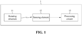
- FIG. 1 is a block diagram of the flow meter of the present invention.
- the flow meter 1 is, for example, a paddle wheel flow meter, a turbine flow meter, a (single/multiple) nozzle impeller flow meter, a gear flow meter, etc., and includes: a rotating structure 11, a sensing element 12, and a processing circuit 13.
- the rotating structure 11 has a magnetic element, which can generate a magnetic field change with the flow of fluid in the pipeline.
- the sensing element 12 and the rotating structure 11 are separated by a distance (for example, one to several tens of millimeters), and are used to sense the change of the magnetic field of the rotating structure 11 to generate a sensing signal.
- the processing circuit 13 is connected to the sensing element 12 and generates the angle of the rotating structure 11 according to the sensing signal.
- the processing circuit 13 can calculate the fluid flow rate in the pipeline on its own according to the angle of the rotating structure 11, or transmit the angle of the rotating structure 11 to a monitoring device loaded with a flow calculation program through a communication module.
- the flow meter 1 further includes a display module (not shown) connected to the processing circuit 13.
- the processing circuit 13 calculates the angular variation of the rotating structure 11 at two time points to obtain the angular velocity of the rotating structure 11, and then calculates the flow rate of the fluid according to the angular velocity of the rotating structure 11 and the cross-sectional area of the pipeline; and the display module displays the flow rate data generated by the processing circuit 13.
- the flow meter 1 further includes a communication module (not shown) connected to the processing circuit 13.
- the communication module transmits the angle of the rotating structure 11 to a monitoring device (not shown) in a wired or wireless manner.
- the monitoring device calculates the angular variation of the rotating structure 11 at two time points to obtain the angular velocity of the rotating structure 11, and then calculates the fluid flow rate according to the angular velocity of the rotating structure 11 and the cross-sectional area of the pipeline.
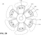
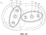
- FIGS. 2A , 2B , and 2C are cross-sectional views of the rotating structure of the paddle wheel flow meter, turbine flow meter, and gear flow meter according to the present invention, respectively.
- the rotating structures 11a, 11b, and 11c have shafts 111a, 111b, 111c, rotating elements 112a, 112b, 112c, and magnetic elements 113a, 113b, 113c, respectively.
- the materials of the shafts 111a, 111b, 111c and the rotating elements 112a, 112b, 112c can be selected from metal and engineering plastics, and the materials of the magnetic elements 113a, 113b, 113c can be selected from alloys with high permeability or ferrite materials.
- the number of the rotating elements 112a, 112b, and 112c is plural, which can be driven by the fluid to rotate around the shafts 111a, 111b, and 111c, respectively. According to the size of the rotation circle of the rotating elements 112a, 112b, 112c, the number of the magnetic elements 113a, 113b, 113c can be single or plural.
- each rotating element 112a, 112b, 112c is provided with a single magnetic element 113a, 113b , 113c, the magnetic elements 113a, 113b, 113c are arranged on one side of the rotating elements 112a, 112b, 112c with two magnetic poles (N/S) parallel to a tangent of the rotation circle of the rotating elements 112a, 112b, 112c, so that the magnetic field lines of the magnetic element 113a, 113b, 113c (as shown by the circular lines in FIGS. 2A , 2B and 2C ) surround the tangent of the rotation circle.
- N/S magnetic poles
- FIG. 2D is a cross-sectional view of the rotating structure of a turbine flow meter according to another embodiment of the present invention.
- the rotating structure 11d has a shaft 111d, a rotating element 112d, and a magnetic element 113d.
- each rotating element 112d is provided with a plurality of magnetic elements 113d, which can enhance the output signals of the sensing element sensing the magnetic field changes.
- the sensing element is an angular displacement magnetic field sensing element, which includes a first sensing unit and a second sensing unit.
- the first sensing unit and the second sensing unit may optionally include, but are not limited to: anisotropic magnetoresistance (AMR) sensor, giant magnetoresistance (GMR) sensor, tunnel magnetoresistance (TMR) sensor, Hall sensor, and so on.
- AMR anisotropic magnetoresistance
- GMR giant magnetoresistance
- TMR tunnel magnetoresistance
- Hall sensor Hall sensor
- the first sensing unit and the second sensing unit are separated from each other by an angle (for example, but not limited to, 45, 90, 135 degrees), and respectively sense the magnetic field of the magnetic element in a first direction and a second direction to generate a first magnetic field component signal and a second magnetic field component signal.
- the two poles of the magnetic elements in the existing paddle wheel flow meters, turbine flow meters and gear flow meters are arranged along the radial direction of the rotating elements (i.e., paddles, blades or gears, etc.).
- the sensing element can only sense the changes in the radial magnetic field intensity of each magnetic element to generate a pulse sensing signal, and cannot generate magnetic field intensity signals in two different directions.
- FIG. 3 is a circuit diagram of a sensing element according to an embodiment of the present invention.
- two sets of Wheatstone bridges are used as the first sensing unit 121 and the second sensing unit 122 of the sensing element 12.
- the first sensing unit 121 and the second sensing unit 122 are arranged perpendicular to each other.
- the first sensing unit 121 senses the intensity and direction of the magnetic field in the vertical direction (the Y axis as shown in FIG. 3 ) to generate the first magnetic field component signal V out-y .
- the second sensing unit 122 senses the intensity and direction of the magnetic field in the horizontal direction (the X axis shown in FIG. 3 ) to generate the second magnetic field component signal Vout-x.
- the sensing element 12 transmits the first magnetic field component signal V out-y and the second magnetic field component signal V out-x to the processing circuit.
- the processing circuit or the monitoring device loaded with a flow calculation program calculates the difference between the rotation angle at the two time points ( ⁇ n - ⁇ n-1 /t n -t n-1 ) to obtain the angular velocity (co) of the rotating structure; by converting the angular velocity (co) of the rotating structure to the flow velocity (v) of the fluid in the pipeline and multiplying it by the preset pipeline cross-sectional area (A), the flow rate of fluid in the pipeline can be obtained.
- the increasing rotation angle of the rotating structure at two time points ( ⁇ n - ⁇ n-1 >0) is defined as counterclockwise rotation
- the decreasing rotation angle of the rotating structure at two time points ( ⁇ n - ⁇ n-1 ⁇ 0) is defined as clockwise rotation.
- the processing circuit can determine the flow direction of the fluid in the pipeline according to the angular variation of the rotating structure (or the direction of rotation of the angular velocity).
- FIG. 4A is a schematic view of the rotation angle and magnetic field intensity signal of an embodiment of the present invention.
- a single magnetic element is provided in the rotating structure, and the processing circuit is set to receive the magnetic field sensing signal of the single magnetic element in advance.
- the closest side and the farthest side between the magnetic element and the sensing element located in the same radial direction of the rotation circle are defined as 0 degrees and 180 degrees, respectively. As shown in FIG.
- the right vertical axis represents the magnetic field intensity (0 to 1) of the sensing element generated by the processing circuit calculating the first magnetic field component signal and the second magnetic field component signal of the magnetic element of the sensing element
- the left vertical axis represents the rotation angle ( ⁇ i ) of magnetic element generated by the processing circuit calculating the first magnetic field component signal and the second magnetic field component signal of the sensing element
- the horizontal axis represents the actual rotation angle ( ⁇ j ) of the rotating structure.
- the processing circuit decreases from the high value to the lowest value, and the processing circuit defines the rotation angle of the rotating structure (as shown by the solid line in FIG. 4A ) as increasing from 0 degrees to 180 degrees; when the rotating structure actually rotates from 180 degrees to 360 degrees, the magnetic field intensity generated by the processing circuit increases from the lowest value to the high value, and the processing circuit defines the rotation angle of the rotating structure as increasing from 180 degrees to 360 degrees, and then the processing circuit generates counting data of one time revolution of the rotating structure.
- the processing circuit can generate the rotating speed (co) of the rotating structure according to rotation angle of the time of one revolution of the rotating structure or according to the rotating angle per unit time (for example, per second), and then generates the fluid flow rate with the rotating speed and the preset pipe cross-sectional area.
- the rotating structure with a larger size is usually used for measuring the flow rate of large pipe diameter pipelines, and it has a larger diameter of the rotating circle. If such the rotating structure were equipped with a single magnetic element, the minimum value of the magnetic field intensity of the sensing element would be too small, and thus the error in the flow data calculated by the processing circuit would be increased. In general, the lowest value of the magnetic field intensity of the sensing element generated by the processing circuit is no less than 0.5, then the rotating structure equipped with a single magnetic element can be selected; the lowest value of the magnetic field intensity of the sensing element generated by the processing circuit is no greater than 0.25, then the rotating structure equipped with a plurality of magnetic elements can be used. To enhance the magnetic field intensity of the magnetic element sensed by the sensing element can effectively reduce the error in the flow rate generated by the processing circuit, and reduce the interference of external magnetic fields.
- FIG. 4B is a schematic view of the rotation angle and magnetic field intensity signal of another embodiment of the present invention.
- the rotating structure is arranged with two opposite magnetic elements (i.e., 180 degrees apart), and the processing circuit is set to receive magnetic field sensing signals of the two magnetic elements in advance.
- the two magnetic elements provided in the rotating structure are respectively defined as the first magnetic element and the second magnetic element.
- the closest side and the farthest side between the first magnetic element and the sensing element located in the same radial direction of the rotation circle are defined as 0 degrees and 180 degrees respectively. As shown in FIG. 4B .
- the right vertical axis represents the magnetic field intensity (0 to 1) of the sensing element generated by the processing circuit calculating the first magnetic field component signal and the second magnetic field component signal of the magnetic element of the sensing element
- the left vertical axis represents the rotation angle ( ⁇ i ) generated by the processing circuit calculating the first magnetic field component signal and the second magnetic field component signal of the first magnetic element and the second magnetic element
- the horizontal axis represents the actual rotation angle ( ⁇ j ) of the rotating structure.
- the processing circuit decreases from the high value to the lowest value, and the processing circuit defines the rotation angle of the rotating structure (as shown by the solid line in FIG. 4B ) as increasing from 0 degrees to 180 degrees; when the rotating structure actually rotates from 90 degrees to 180 degrees, the magnetic field intensity generated by the processing circuit increases from the lowest value to the high value, and the processing circuit defines the rotation angle of the rotating structure as increasing from 180 degrees to 360 degrees; when the rotating structure actually rotates from 180 degrees to 270 degrees, the magnetic field intensity generated by the processing circuit decreases from the high value to the lowest value again, and the processing circuit defines the rotation angle of the rotating structure as increasing from 0 degrees to 180 degrees again; when the rotating structure actually rotates from 270 degrees to 360 degrees, the magnetic field intensity generated by the processing circuit increases from the lowest value to the high value again, and the processing circuit defines the rotation angle of the rotating structure as increasing from 180 degrees to 360 degrees again.
- the processing circuit When the rotating structure rotates twice from 0 to 360 degrees defined by the processing circuit, the processing circuit generates the counting data of one time revolution of the rotating structure, generates the rotating speed (co) of the rotating structure according to the rotation angle of the time of one revolution of the rotating structure or the rotation angle per unit time (for example, per second), and then generates the fluid flow rate with the rotating speed and the preset pipe cross-sectional area.
- the processing circuit Since the processing circuit generates the angle (rotation angle) and angular velocity (rotation speed) of the rotating structure according to the magnetic field component signals of the magnetic element in two directions, as long as the sensing element can sense the magnetic field intensity change of the magnetic element, the rotation angle generated by the processing circuit is not related to the magnetic field intensity of the magnetic element, and a very small amount of rotation angle variation can be calculated, so that the sensitivity and accuracy of the flow meter to measure low flow rate are greatly improved.
- FIG. 5 is a schematic view of the magnetic field intensity of an embodiment of the present invention.
- the processing circuit stored the upper bound of the magnetic field intensity and the lower bound of the magnetic field intensity of the magnetic element in advance.
- the vertical axis represents the magnetic field intensity (R) of the magnetic element sensed by the sensing element
- the horizontal axis corresponds to the rotation angle of the rotating structure for one revolution.
- the processing circuit generates the magnetic field intensity based on the first magnetic field component signal and the second magnetic field component signal of the magnetic element,.
- the processing circuit can monitor the external magnetic field interference of the sensing element and the operating state of the rotating structure, so that the measurement error and gap of the flow meter are effectively reduced.
- the flow meter of the present invention includes a rotating structure, a sensing element, and a processing circuit.
- the rotating structure has a magnetic element with two magnetic poles parallel to the tangent of the rotating circle, the sensing element generates a first magnetic field component signal and a second magnetic field component signal of the magnetic element in different directions, and the processing circuit can calculate extremely small rotation angular variation and magnetic field intensity based on the two magnetic field component signals in different directions.
- the processing circuit can calculate fluid flow rate, and can further determine the fluid flow direction and whether the rotating structure is lossy, or whether there is an abnormality such as external magnetic field interference.
- the flow meter of the present invention can greatly improve the sensitivity and accuracy of measuring low flow rates, and reduce measurement error and gap.
Landscapes
- Physics & Mathematics (AREA)
- General Physics & Mathematics (AREA)
- Fluid Mechanics (AREA)
- Electromagnetism (AREA)
- Measuring Volume Flow (AREA)
Applications Claiming Priority (1)
| Application Number | Priority Date | Filing Date | Title |
|---|---|---|---|
| TW108130346A TWI716086B (zh) | 2019-08-23 | 2019-08-23 | 流量計 |
Publications (3)
| Publication Number | Publication Date |
|---|---|
| EP3783319A2 true EP3783319A2 (fr) | 2021-02-24 |
| EP3783319A3 EP3783319A3 (fr) | 2021-03-03 |
| EP3783319B1 EP3783319B1 (fr) | 2023-05-10 |
Family
ID=72046728
Family Applications (1)
| Application Number | Title | Priority Date | Filing Date |
|---|---|---|---|
| EP20190435.6A Active EP3783319B1 (fr) | 2019-08-23 | 2020-08-11 | Débitmètre |
Country Status (4)
| Country | Link |
|---|---|
| US (1) | US11397101B2 (fr) |
| EP (1) | EP3783319B1 (fr) |
| CN (1) | CN112414478B (fr) |
| TW (1) | TWI716086B (fr) |
Families Citing this family (1)
| Publication number | Priority date | Publication date | Assignee | Title |
|---|---|---|---|---|
| CN114383692B (zh) * | 2022-01-10 | 2023-06-16 | 宁波东海集团有限公司 | 一种水表检测方法、系统、存储介质及智能终端 |
Family Cites Families (17)
| Publication number | Priority date | Publication date | Assignee | Title |
|---|---|---|---|---|
| WO2005048105A1 (fr) * | 2003-11-04 | 2005-05-26 | Neptune Technology Group, Inc. | Procede de detection d'erreurs et de determination du sens de l'ecoulement dans un appareil de mesure |
| BRPI0318248B1 (pt) * | 2003-04-17 | 2018-12-11 | Micro Motion Inc | método e aparelho para o equilíbrio de forças em um medidor de vazão do tipo coriolis |
| JP2006098183A (ja) * | 2004-09-29 | 2006-04-13 | Matsushita Electric Ind Co Ltd | 流量計測装置 |
| WO2006035888A1 (fr) * | 2004-09-29 | 2006-04-06 | Matsushita Electric Industrial Co., Ltd. | Dispositif de mesure de debit |
| DE102005016373B4 (de) * | 2005-04-09 | 2008-01-31 | SIKA Dr. Siebert & Kühn GmbH & Co. KG | Wasserzähler, umfassend ein Messsystem zur Messung einer Durchflussmenge |
| US7360454B2 (en) * | 2005-05-11 | 2008-04-22 | Ebara Corporation | Flowmeter having a float and a displacement sensor |
| EP2668473A1 (fr) * | 2011-01-24 | 2013-12-04 | M.T.R. Wireless Communications Ltd. | Débitmètre |
| US9182456B2 (en) * | 2012-03-06 | 2015-11-10 | Allegro Microsystems, Llc | Magnetic field sensor for sensing rotation of an object |
| CN104360403B (zh) * | 2014-11-08 | 2017-06-27 | 长安大学 | 一种多辐射场源瞬变电磁法多分量全域视电阻率定义方法 |
| US9759578B2 (en) * | 2015-03-12 | 2017-09-12 | International Business Machines Corporation | Sensor arrangement for position sensing |
| CN205687655U (zh) * | 2015-11-09 | 2016-11-16 | 温州任和文化创意有限责任公司 | 一种同轴电磁式循环水处理设备 |
| TWI595217B (zh) * | 2016-06-16 | 2017-08-11 | 桓達科技股份有限公司 | 自發電蹼輪流量計 |
| CN106443059A (zh) * | 2016-09-07 | 2017-02-22 | 成都千嘉科技有限公司 | 一种流体速度测量方法及流体计量方法及流量计 |
| JP6782602B2 (ja) * | 2016-10-05 | 2020-11-11 | アズビル株式会社 | 流体計測回転計 |
| TWI638140B (zh) * | 2016-11-09 | 2018-10-11 | 愛盛科技股份有限公司 | 磁場感測裝置 |
| JP2020101497A (ja) * | 2018-12-25 | 2020-07-02 | 株式会社ノーリツ | 水量センサユニットおよび温水装置 |
| US11624636B2 (en) * | 2019-05-07 | 2023-04-11 | Fortune Brands Water Innovations LLC | Turbine design for flow meter |
-
2019
- 2019-08-23 TW TW108130346A patent/TWI716086B/zh active
-
2020
- 2020-08-11 EP EP20190435.6A patent/EP3783319B1/fr active Active
- 2020-08-11 CN CN202010800022.1A patent/CN112414478B/zh active Active
- 2020-08-17 US US16/995,260 patent/US11397101B2/en active Active
Also Published As
| Publication number | Publication date |
|---|---|
| EP3783319A3 (fr) | 2021-03-03 |
| CN112414478A (zh) | 2021-02-26 |
| US20210055142A1 (en) | 2021-02-25 |
| EP3783319B1 (fr) | 2023-05-10 |
| TWI716086B (zh) | 2021-01-11 |
| CN112414478B (zh) | 2025-05-27 |
| TW202108987A (zh) | 2021-03-01 |
| US11397101B2 (en) | 2022-07-26 |
Similar Documents
| Publication | Publication Date | Title |
|---|---|---|
| CN101490513B (zh) | 椭圆形齿轮计 | |
| CN102589412B (zh) | 角度传感器 | |
| JPH0461283B2 (fr) | ||
| JP2009537818A (ja) | ブルドン圧力ゲージの感知装置 | |
| WO2016175800A1 (fr) | Procédé de détermination d'une position d'un élément de fermeture de soupape déplacé par un arbre d'actionneur de soupape rotatif | |
| US7650800B2 (en) | Flow sensor and method for measuring the volume and/or flow speed of a medium | |
| US11397101B2 (en) | Flow meter | |
| US5473932A (en) | Tandem rotor turbine meter and field calibration module | |
| EP2141462B1 (fr) | Dispositif électronique pour mesurer le mouvement d'un mécanisme de vis | |
| KR101329178B1 (ko) | 광센서를 이용한 유량측정장치 및 방법 | |
| CN202734886U (zh) | 流量计中的反转防计数装置 | |
| AU2010206097B2 (en) | Improved positive displacement flowmeter | |
| CN114739465B (zh) | 一种智能水表机电转换方法 | |
| KR101582529B1 (ko) | 카운터 타입의 앱솔루트 엔코더 | |
| CN104568021A (zh) | 三螺杆流量计 | |
| US20130047744A1 (en) | Positive displacement flow meter | |
| CN111486905A (zh) | 扭矩流量计 | |
| JPH04318426A (ja) | 流量計 | |
| JP4245414B2 (ja) | 回転検出器、容積式流量計、及び回転検出方法 | |
| JP2001324365A (ja) | 容積式流量計の器差補正方法 | |
| KR20140044137A (ko) | 유량 측정 장치 | |
| EP2771650A1 (fr) | Compteur à gaz à double turbine | |
| JPH0645210Y2 (ja) | 流量計 | |
| JP2786687B2 (ja) | 容積流量計の発信方式 | |
| CN206056682U (zh) | 正逆流量计 |
Legal Events
| Date | Code | Title | Description |
|---|---|---|---|
| PUAI | Public reference made under article 153(3) epc to a published international application that has entered the european phase |
Free format text: ORIGINAL CODE: 0009012 |
|
| STAA | Information on the status of an ep patent application or granted ep patent |
Free format text: STATUS: THE APPLICATION HAS BEEN PUBLISHED |
|
| PUAL | Search report despatched |
Free format text: ORIGINAL CODE: 0009013 |
|
| AK | Designated contracting states |
Kind code of ref document: A2 Designated state(s): AL AT BE BG CH CY CZ DE DK EE ES FI FR GB GR HR HU IE IS IT LI LT LU LV MC MK MT NL NO PL PT RO RS SE SI SK SM TR |
|
| AX | Request for extension of the european patent |
Extension state: BA ME |
|
| AK | Designated contracting states |
Kind code of ref document: A3 Designated state(s): AL AT BE BG CH CY CZ DE DK EE ES FI FR GB GR HR HU IE IS IT LI LT LU LV MC MK MT NL NO PL PT RO RS SE SI SK SM TR |
|
| AX | Request for extension of the european patent |
Extension state: BA ME |
|
| RIC1 | Information provided on ipc code assigned before grant |
Ipc: G01F 3/10 20060101AFI20210128BHEP Ipc: G01F 1/115 20060101ALI20210128BHEP Ipc: G01F 15/00 20060101ALI20210128BHEP Ipc: G01F 15/06 20060101ALI20210128BHEP Ipc: G01F 1/08 20060101ALI20210128BHEP Ipc: G01F 1/075 20060101ALI20210128BHEP Ipc: G01F 1/12 20060101ALI20210128BHEP |
|
| STAA | Information on the status of an ep patent application or granted ep patent |
Free format text: STATUS: REQUEST FOR EXAMINATION WAS MADE |
|
| 17P | Request for examination filed |
Effective date: 20210831 |
|
| RBV | Designated contracting states (corrected) |
Designated state(s): AL AT BE BG CH CY CZ DE DK EE ES FI FR GB GR HR HU IE IS IT LI LT LU LV MC MK MT NL NO PL PT RO RS SE SI SK SM TR |
|
| GRAP | Despatch of communication of intention to grant a patent |
Free format text: ORIGINAL CODE: EPIDOSNIGR1 |
|
| STAA | Information on the status of an ep patent application or granted ep patent |
Free format text: STATUS: GRANT OF PATENT IS INTENDED |
|
| INTG | Intention to grant announced |
Effective date: 20230119 |
|
| GRAS | Grant fee paid |
Free format text: ORIGINAL CODE: EPIDOSNIGR3 |
|
| GRAA | (expected) grant |
Free format text: ORIGINAL CODE: 0009210 |
|
| STAA | Information on the status of an ep patent application or granted ep patent |
Free format text: STATUS: THE PATENT HAS BEEN GRANTED |
|
| AK | Designated contracting states |
Kind code of ref document: B1 Designated state(s): AL AT BE BG CH CY CZ DE DK EE ES FI FR GB GR HR HU IE IS IT LI LT LU LV MC MK MT NL NO PL PT RO RS SE SI SK SM TR |
|
| REG | Reference to a national code |
Ref country code: GB Ref legal event code: FG4D |
|
| REG | Reference to a national code |
Ref country code: AT Ref legal event code: REF Ref document number: 1567100 Country of ref document: AT Kind code of ref document: T Effective date: 20230515 Ref country code: CH Ref legal event code: EP |
|
| REG | Reference to a national code |
Ref country code: DE Ref legal event code: R096 Ref document number: 602020010655 Country of ref document: DE |
|
| REG | Reference to a national code |
Ref country code: IE Ref legal event code: FG4D |
|
| P01 | Opt-out of the competence of the unified patent court (upc) registered |
Effective date: 20230403 |
|
| REG | Reference to a national code |
Ref country code: LT Ref legal event code: MG9D |
|
| REG | Reference to a national code |
Ref country code: NL Ref legal event code: MP Effective date: 20230510 |
|
| REG | Reference to a national code |
Ref country code: AT Ref legal event code: MK05 Ref document number: 1567100 Country of ref document: AT Kind code of ref document: T Effective date: 20230510 |
|
| PG25 | Lapsed in a contracting state [announced via postgrant information from national office to epo] |
Ref country code: SE Free format text: LAPSE BECAUSE OF FAILURE TO SUBMIT A TRANSLATION OF THE DESCRIPTION OR TO PAY THE FEE WITHIN THE PRESCRIBED TIME-LIMIT Effective date: 20230510 Ref country code: PT Free format text: LAPSE BECAUSE OF FAILURE TO SUBMIT A TRANSLATION OF THE DESCRIPTION OR TO PAY THE FEE WITHIN THE PRESCRIBED TIME-LIMIT Effective date: 20230911 Ref country code: NO Free format text: LAPSE BECAUSE OF FAILURE TO SUBMIT A TRANSLATION OF THE DESCRIPTION OR TO PAY THE FEE WITHIN THE PRESCRIBED TIME-LIMIT Effective date: 20230810 Ref country code: NL Free format text: LAPSE BECAUSE OF FAILURE TO SUBMIT A TRANSLATION OF THE DESCRIPTION OR TO PAY THE FEE WITHIN THE PRESCRIBED TIME-LIMIT Effective date: 20230510 Ref country code: ES Free format text: LAPSE BECAUSE OF FAILURE TO SUBMIT A TRANSLATION OF THE DESCRIPTION OR TO PAY THE FEE WITHIN THE PRESCRIBED TIME-LIMIT Effective date: 20230510 Ref country code: AT Free format text: LAPSE BECAUSE OF FAILURE TO SUBMIT A TRANSLATION OF THE DESCRIPTION OR TO PAY THE FEE WITHIN THE PRESCRIBED TIME-LIMIT Effective date: 20230510 |
|
| PG25 | Lapsed in a contracting state [announced via postgrant information from national office to epo] |
Ref country code: RS Free format text: LAPSE BECAUSE OF FAILURE TO SUBMIT A TRANSLATION OF THE DESCRIPTION OR TO PAY THE FEE WITHIN THE PRESCRIBED TIME-LIMIT Effective date: 20230510 Ref country code: PL Free format text: LAPSE BECAUSE OF FAILURE TO SUBMIT A TRANSLATION OF THE DESCRIPTION OR TO PAY THE FEE WITHIN THE PRESCRIBED TIME-LIMIT Effective date: 20230510 Ref country code: LV Free format text: LAPSE BECAUSE OF FAILURE TO SUBMIT A TRANSLATION OF THE DESCRIPTION OR TO PAY THE FEE WITHIN THE PRESCRIBED TIME-LIMIT Effective date: 20230510 Ref country code: LT Free format text: LAPSE BECAUSE OF FAILURE TO SUBMIT A TRANSLATION OF THE DESCRIPTION OR TO PAY THE FEE WITHIN THE PRESCRIBED TIME-LIMIT Effective date: 20230510 Ref country code: IS Free format text: LAPSE BECAUSE OF FAILURE TO SUBMIT A TRANSLATION OF THE DESCRIPTION OR TO PAY THE FEE WITHIN THE PRESCRIBED TIME-LIMIT Effective date: 20230910 Ref country code: HR Free format text: LAPSE BECAUSE OF FAILURE TO SUBMIT A TRANSLATION OF THE DESCRIPTION OR TO PAY THE FEE WITHIN THE PRESCRIBED TIME-LIMIT Effective date: 20230510 Ref country code: GR Free format text: LAPSE BECAUSE OF FAILURE TO SUBMIT A TRANSLATION OF THE DESCRIPTION OR TO PAY THE FEE WITHIN THE PRESCRIBED TIME-LIMIT Effective date: 20230811 |
|
| PG25 | Lapsed in a contracting state [announced via postgrant information from national office to epo] |
Ref country code: FI Free format text: LAPSE BECAUSE OF FAILURE TO SUBMIT A TRANSLATION OF THE DESCRIPTION OR TO PAY THE FEE WITHIN THE PRESCRIBED TIME-LIMIT Effective date: 20230510 |
|
| PG25 | Lapsed in a contracting state [announced via postgrant information from national office to epo] |
Ref country code: SK Free format text: LAPSE BECAUSE OF FAILURE TO SUBMIT A TRANSLATION OF THE DESCRIPTION OR TO PAY THE FEE WITHIN THE PRESCRIBED TIME-LIMIT Effective date: 20230510 |
|
| PG25 | Lapsed in a contracting state [announced via postgrant information from national office to epo] |
Ref country code: SM Free format text: LAPSE BECAUSE OF FAILURE TO SUBMIT A TRANSLATION OF THE DESCRIPTION OR TO PAY THE FEE WITHIN THE PRESCRIBED TIME-LIMIT Effective date: 20230510 Ref country code: SK Free format text: LAPSE BECAUSE OF FAILURE TO SUBMIT A TRANSLATION OF THE DESCRIPTION OR TO PAY THE FEE WITHIN THE PRESCRIBED TIME-LIMIT Effective date: 20230510 Ref country code: RO Free format text: LAPSE BECAUSE OF FAILURE TO SUBMIT A TRANSLATION OF THE DESCRIPTION OR TO PAY THE FEE WITHIN THE PRESCRIBED TIME-LIMIT Effective date: 20230510 Ref country code: EE Free format text: LAPSE BECAUSE OF FAILURE TO SUBMIT A TRANSLATION OF THE DESCRIPTION OR TO PAY THE FEE WITHIN THE PRESCRIBED TIME-LIMIT Effective date: 20230510 Ref country code: DK Free format text: LAPSE BECAUSE OF FAILURE TO SUBMIT A TRANSLATION OF THE DESCRIPTION OR TO PAY THE FEE WITHIN THE PRESCRIBED TIME-LIMIT Effective date: 20230510 Ref country code: CZ Free format text: LAPSE BECAUSE OF FAILURE TO SUBMIT A TRANSLATION OF THE DESCRIPTION OR TO PAY THE FEE WITHIN THE PRESCRIBED TIME-LIMIT Effective date: 20230510 |
|
| REG | Reference to a national code |
Ref country code: DE Ref legal event code: R097 Ref document number: 602020010655 Country of ref document: DE |
|
| PG25 | Lapsed in a contracting state [announced via postgrant information from national office to epo] |
Ref country code: MC Free format text: LAPSE BECAUSE OF FAILURE TO SUBMIT A TRANSLATION OF THE DESCRIPTION OR TO PAY THE FEE WITHIN THE PRESCRIBED TIME-LIMIT Effective date: 20230510 |
|
| PLBE | No opposition filed within time limit |
Free format text: ORIGINAL CODE: 0009261 |
|
| STAA | Information on the status of an ep patent application or granted ep patent |
Free format text: STATUS: NO OPPOSITION FILED WITHIN TIME LIMIT |
|
| REG | Reference to a national code |
Ref country code: CH Ref legal event code: PL |
|
| PG25 | Lapsed in a contracting state [announced via postgrant information from national office to epo] |
Ref country code: MC Free format text: LAPSE BECAUSE OF FAILURE TO SUBMIT A TRANSLATION OF THE DESCRIPTION OR TO PAY THE FEE WITHIN THE PRESCRIBED TIME-LIMIT Effective date: 20230510 |
|
| PG25 | Lapsed in a contracting state [announced via postgrant information from national office to epo] |
Ref country code: LU Free format text: LAPSE BECAUSE OF NON-PAYMENT OF DUE FEES Effective date: 20230811 |
|
| 26N | No opposition filed |
Effective date: 20240213 |
|
| PG25 | Lapsed in a contracting state [announced via postgrant information from national office to epo] |
Ref country code: LU Free format text: LAPSE BECAUSE OF NON-PAYMENT OF DUE FEES Effective date: 20230811 Ref country code: CH Free format text: LAPSE BECAUSE OF NON-PAYMENT OF DUE FEES Effective date: 20230831 |
|
| PG25 | Lapsed in a contracting state [announced via postgrant information from national office to epo] |
Ref country code: SI Free format text: LAPSE BECAUSE OF FAILURE TO SUBMIT A TRANSLATION OF THE DESCRIPTION OR TO PAY THE FEE WITHIN THE PRESCRIBED TIME-LIMIT Effective date: 20230510 |
|
| REG | Reference to a national code |
Ref country code: BE Ref legal event code: MM Effective date: 20230831 |
|
| REG | Reference to a national code |
Ref country code: IE Ref legal event code: MM4A |
|
| PG25 | Lapsed in a contracting state [announced via postgrant information from national office to epo] |
Ref country code: SI Free format text: LAPSE BECAUSE OF FAILURE TO SUBMIT A TRANSLATION OF THE DESCRIPTION OR TO PAY THE FEE WITHIN THE PRESCRIBED TIME-LIMIT Effective date: 20230510 Ref country code: IT Free format text: LAPSE BECAUSE OF FAILURE TO SUBMIT A TRANSLATION OF THE DESCRIPTION OR TO PAY THE FEE WITHIN THE PRESCRIBED TIME-LIMIT Effective date: 20230510 |
|
| PG25 | Lapsed in a contracting state [announced via postgrant information from national office to epo] |
Ref country code: IE Free format text: LAPSE BECAUSE OF NON-PAYMENT OF DUE FEES Effective date: 20230811 |
|
| PG25 | Lapsed in a contracting state [announced via postgrant information from national office to epo] |
Ref country code: IE Free format text: LAPSE BECAUSE OF NON-PAYMENT OF DUE FEES Effective date: 20230811 Ref country code: FR Free format text: LAPSE BECAUSE OF NON-PAYMENT OF DUE FEES Effective date: 20230831 |
|
| PG25 | Lapsed in a contracting state [announced via postgrant information from national office to epo] |
Ref country code: BE Free format text: LAPSE BECAUSE OF NON-PAYMENT OF DUE FEES Effective date: 20230831 |
|
| PG25 | Lapsed in a contracting state [announced via postgrant information from national office to epo] |
Ref country code: BG Free format text: LAPSE BECAUSE OF FAILURE TO SUBMIT A TRANSLATION OF THE DESCRIPTION OR TO PAY THE FEE WITHIN THE PRESCRIBED TIME-LIMIT Effective date: 20230510 |
|
| PG25 | Lapsed in a contracting state [announced via postgrant information from national office to epo] |
Ref country code: BG Free format text: LAPSE BECAUSE OF FAILURE TO SUBMIT A TRANSLATION OF THE DESCRIPTION OR TO PAY THE FEE WITHIN THE PRESCRIBED TIME-LIMIT Effective date: 20230510 |
|
| GBPC | Gb: european patent ceased through non-payment of renewal fee |
Effective date: 20240811 |
|
| PG25 | Lapsed in a contracting state [announced via postgrant information from national office to epo] |
Ref country code: GB Free format text: LAPSE BECAUSE OF NON-PAYMENT OF DUE FEES Effective date: 20240811 |
|
| PG25 | Lapsed in a contracting state [announced via postgrant information from national office to epo] |
Ref country code: CY Free format text: LAPSE BECAUSE OF FAILURE TO SUBMIT A TRANSLATION OF THE DESCRIPTION OR TO PAY THE FEE WITHIN THE PRESCRIBED TIME-LIMIT; INVALID AB INITIO Effective date: 20200811 |
|
| PG25 | Lapsed in a contracting state [announced via postgrant information from national office to epo] |
Ref country code: HU Free format text: LAPSE BECAUSE OF FAILURE TO SUBMIT A TRANSLATION OF THE DESCRIPTION OR TO PAY THE FEE WITHIN THE PRESCRIBED TIME-LIMIT; INVALID AB INITIO Effective date: 20200811 |
|
| PGFP | Annual fee paid to national office [announced via postgrant information from national office to epo] |
Ref country code: DE Payment date: 20250612 Year of fee payment: 6 |
|
| PG25 | Lapsed in a contracting state [announced via postgrant information from national office to epo] |
Ref country code: TR Free format text: LAPSE BECAUSE OF FAILURE TO SUBMIT A TRANSLATION OF THE DESCRIPTION OR TO PAY THE FEE WITHIN THE PRESCRIBED TIME-LIMIT Effective date: 20230510 |