EP3783726A1 - Vorrichtung zur bildung von batterien - Google Patents
Vorrichtung zur bildung von batterien Download PDFInfo
- Publication number
- EP3783726A1 EP3783726A1 EP19752910.0A EP19752910A EP3783726A1 EP 3783726 A1 EP3783726 A1 EP 3783726A1 EP 19752910 A EP19752910 A EP 19752910A EP 3783726 A1 EP3783726 A1 EP 3783726A1
- Authority
- EP
- European Patent Office
- Prior art keywords
- hole
- base plate
- connecting pipe
- battery
- nozzle
- Prior art date
- Legal status (The legal status is an assumption and is not a legal conclusion. Google has not performed a legal analysis and makes no representation as to the accuracy of the status listed.)
- Granted
Links
Images


Classifications
-
- H—ELECTRICITY
- H01—ELECTRIC ELEMENTS
- H01M—PROCESSES OR MEANS, e.g. BATTERIES, FOR THE DIRECT CONVERSION OF CHEMICAL ENERGY INTO ELECTRICAL ENERGY
- H01M10/00—Secondary cells; Manufacture thereof
- H01M10/05—Accumulators with non-aqueous electrolyte
- H01M10/052—Li-accumulators
- H01M10/0525—Rocking-chair batteries, i.e. batteries with lithium insertion or intercalation in both electrodes; Lithium-ion batteries
-
- H—ELECTRICITY
- H01—ELECTRIC ELEMENTS
- H01M—PROCESSES OR MEANS, e.g. BATTERIES, FOR THE DIRECT CONVERSION OF CHEMICAL ENERGY INTO ELECTRICAL ENERGY
- H01M10/00—Secondary cells; Manufacture thereof
- H01M10/04—Construction or manufacture in general
- H01M10/0404—Machines for assembling batteries
-
- H—ELECTRICITY
- H01—ELECTRIC ELEMENTS
- H01M—PROCESSES OR MEANS, e.g. BATTERIES, FOR THE DIRECT CONVERSION OF CHEMICAL ENERGY INTO ELECTRICAL ENERGY
- H01M10/00—Secondary cells; Manufacture thereof
- H01M10/42—Methods or arrangements for servicing or maintenance of secondary cells or secondary half-cells
- H01M10/52—Removing gases inside the secondary cell, e.g. by absorption
-
- H—ELECTRICITY
- H01—ELECTRIC ELEMENTS
- H01M—PROCESSES OR MEANS, e.g. BATTERIES, FOR THE DIRECT CONVERSION OF CHEMICAL ENERGY INTO ELECTRICAL ENERGY
- H01M50/00—Constructional details or processes of manufacture of the non-active parts of electrochemical cells other than fuel cells, e.g. hybrid cells
- H01M50/30—Arrangements for facilitating escape of gases
-
- H—ELECTRICITY
- H01—ELECTRIC ELEMENTS
- H01M—PROCESSES OR MEANS, e.g. BATTERIES, FOR THE DIRECT CONVERSION OF CHEMICAL ENERGY INTO ELECTRICAL ENERGY
- H01M50/00—Constructional details or processes of manufacture of the non-active parts of electrochemical cells other than fuel cells, e.g. hybrid cells
- H01M50/60—Arrangements or processes for filling or topping-up with liquids; Arrangements or processes for draining liquids from casings
- H01M50/609—Arrangements or processes for filling with liquid, e.g. electrolytes
- H01M50/618—Pressure control
-
- H—ELECTRICITY
- H01—ELECTRIC ELEMENTS
- H01M—PROCESSES OR MEANS, e.g. BATTERIES, FOR THE DIRECT CONVERSION OF CHEMICAL ENERGY INTO ELECTRICAL ENERGY
- H01M50/00—Constructional details or processes of manufacture of the non-active parts of electrochemical cells other than fuel cells, e.g. hybrid cells
- H01M50/60—Arrangements or processes for filling or topping-up with liquids; Arrangements or processes for draining liquids from casings
- H01M50/609—Arrangements or processes for filling with liquid, e.g. electrolytes
- H01M50/627—Filling ports
- H01M50/636—Closing or sealing filling ports, e.g. using lids
- H01M50/645—Plugs
- H01M50/655—Plugs specially adapted for venting
-
- H—ELECTRICITY
- H01—ELECTRIC ELEMENTS
- H01M—PROCESSES OR MEANS, e.g. BATTERIES, FOR THE DIRECT CONVERSION OF CHEMICAL ENERGY INTO ELECTRICAL ENERGY
- H01M2300/00—Electrolytes
- H01M2300/0017—Non-aqueous electrolytes
- H01M2300/0025—Organic electrolyte
-
- Y—GENERAL TAGGING OF NEW TECHNOLOGICAL DEVELOPMENTS; GENERAL TAGGING OF CROSS-SECTIONAL TECHNOLOGIES SPANNING OVER SEVERAL SECTIONS OF THE IPC; TECHNICAL SUBJECTS COVERED BY FORMER USPC CROSS-REFERENCE ART COLLECTIONS [XRACs] AND DIGESTS
- Y02—TECHNOLOGIES OR APPLICATIONS FOR MITIGATION OR ADAPTATION AGAINST CLIMATE CHANGE
- Y02E—REDUCTION OF GREENHOUSE GAS [GHG] EMISSIONS, RELATED TO ENERGY GENERATION, TRANSMISSION OR DISTRIBUTION
- Y02E60/00—Enabling technologies; Technologies with a potential or indirect contribution to GHG emissions mitigation
- Y02E60/10—Energy storage using batteries
-
- Y—GENERAL TAGGING OF NEW TECHNOLOGICAL DEVELOPMENTS; GENERAL TAGGING OF CROSS-SECTIONAL TECHNOLOGIES SPANNING OVER SEVERAL SECTIONS OF THE IPC; TECHNICAL SUBJECTS COVERED BY FORMER USPC CROSS-REFERENCE ART COLLECTIONS [XRACs] AND DIGESTS
- Y02—TECHNOLOGIES OR APPLICATIONS FOR MITIGATION OR ADAPTATION AGAINST CLIMATE CHANGE
- Y02P—CLIMATE CHANGE MITIGATION TECHNOLOGIES IN THE PRODUCTION OR PROCESSING OF GOODS
- Y02P70/00—Climate change mitigation technologies in the production process for final industrial or consumer products
- Y02P70/50—Manufacturing or production processes characterised by the final manufactured product
Definitions
- the present invention relates to the field of battery production, and particularly relates to a device for battery formation.
- the formation process plays a key role on the quality of the battery.
- a large amount of gases are generated in the battery, so it needs a corresponding device for formation to degas timely.
- it can connect the device for formation to an electrolyte injection hole of the battery, and then degas the battery by using the negative pressure of a vacuuming device.
- the model changing process of the known device for formation is complex, which leads to the efficiency of the battery formation process low.
- an object of the present invention is to provide a device for battery formation, which can simplify the production process and improve efficiency.
- the present invention provides a device for battery formation, which comprises a base plate, a press plate, a positioning block and a connecting assembly.
- the press plate is connected with the base plate, the positioning block and the connecting assembly each are provided as plurality in number and the plurality of the connecting assemblies correspond to the plurality of positioning blocks.
- the positioning block has a main portion and a protruding portion, the main portion is provided between the base plate and the press plate, and the protruding portion extends from a surface of the main portion away from the press plate.
- the base plate is provided with a plurality of positioning holes, and the protruding portion of each positioning block is inserted into the positioning hole.
- Each connecting assembly is provided to the main portion of a corresponding positioning block and used for being connected to a battery.
- the main portion is provided with a first through-hole.
- the connecting assembly comprises a first connecting pipe and a nozzle, one end of the first connecting pipe is connected with the nozzle, the other end of the first connecting pipe passes through the first through-hole of the main portion and is connected with the main portion.
- the connecting assembly further comprises a spring, the spring sheathes the first connecting pipe and is positioned between the nozzle and the main portion.
- the first connecting pipe is a metal pipe.
- the connecting assembly further comprises a second connecting pipe, the second connecting pipe is connected with one end of the first connecting pipe away from the nozzle.
- the second connecting pipe is a flexible pipe.
- the nozzle is positioned at a side of the press plate away from the base plate.
- the press plate is provided with a second through-hole in the shape of strip
- the base plate is provided with a third through-hole in the shape of strip
- the second through-hole and the third through-hole are respectively positioned at two sides of the first through-hole.
- the first connecting pipes of the plurality of connecting assemblies pass through the second through-hole, and the third through-hole exposes one end of the first connecting pipe away from the nozzle.
- the base plate has a groove, the groove is recessed relative to a surface of the base plate close to the press plate. At least a part of the main portion of the positioning block is received in the groove.
- the third through-hole and the positioning hole are formed to a bottom wall of the groove away from the press plate.
- the number of the positioning holes is greater than the total number of the protruding portions.
- each positioning block is provided as plurality in number.
- the device for battery formation further comprises a negative pressure mechanism, the negative pressure mechanism is positioned at a side of the base plate away from the press plate, and the negative pressure mechanism is connected with the base plate.
- the plurality of connecting assemblies are connected with the negative pressure mechanism.
- the device for battery formation of the present invention can connect the vacuuming device and batteries, and degas the batteries in the formation process.
- the positioning blocks are fixed by the fit between the base plate and the press plate, so when assembling or disassembling the positioning blocks, it only needs to rotating the bolts between the press plate and the base plate, and there is no need to provide fasteners to each positioning block. Therefore, the assembling and the disassembling of the positioning blocks of the present invention are convenient, thereby effectively simplifying the production process and improving efficiency.
- the terms “first”, “second”, “third” and the like are only used for illustrative purposes and are not to be construed as expressing or implying a relative importance.
- the term “plurality” is two or more.
- the term “connect” should be broadly interpreted, for example, the term “connect” can be “fixedly connect”, “detachably connect”, “integrally connect”, “electrically connect” or “signal connect”.
- the term “connect” also can be “directly connect” or “indirectly connect via a medium”.
- a device for battery formation of the present invention can be used for a formation process of battery 8; specifically, the device for battery formation can be used for degassing the battery 8 in the process of formation.
- the battery 8 may be a lithium-ion battery.
- the battery 8 may comprise a case, an electrode assembly and an electrolyte, the electrode assembly and the electrolyte are received in the case.
- the device for battery formation of the present invention comprises a base plate 1, a press plate 2, a positioning block 3 and a connecting assembly 4.
- the base plate 1 may be fixed to an external frame by bolts.
- the press plate 2 is connected with the base plate 1; preferably, the press plate 2 is positioned below the base plate 1 in an height direction Z and connected with the base plate 1 by bolts.
- the positioning block 3 is provided as plurality in number and the plurality of positioning blocks 3 are positioned between the base plate 1 and the press plate 2. Specifically, referring to FIG. 3 and FIG. 4 , the positioning block 3 has a main portion 31 and a protruding portion 32, the main portion 31 is provided between the base plate 1 and the press plate 2, and the protruding portion 32 extends from a surface of the main portion 31 away from the press plate 2. Referring to FIG. 5 , the base plate 1 is provided with a plurality of positioning holes 11, and the protruding portion 32 of each positioning block 3 is inserted into the positioning hole 11.
- the press plate 2 and the base plate 1 may be connected by bolts. By rotating the bolts, it can adjust a distance between the press plate 2 and the base plate 1 in the height direction Z.
- the bolts are loosened to increase the distance between the press plate 2 and the base plate 1, then the positioning blocks 3 are positioned on the press plate 2, and the protruding portion 32 of the positioning block 3 is made to correspond to the positioning hole 11 of the base plate 1.
- the distance between the press plate 2 and the base plate 1 is decreased by tightening the bolts, so that the protruding portion 32 is inserted into the positioning hole 11 and the main portion 31 is clamped between the press plate 2 and the base plate 1.
- the connecting assembly 4 is provided as plurality in number, and each connecting assembly 4 is provided to the main portion 31 of a corresponding positioning block 3.
- the connecting assembly 4 is used for connecting a battery 8 and a vacuuming device. Specifically, one end of the connecting assembly 4 can be connected with the vacuuming device, the other end of the connecting assembly 4 can be connected with an electrolyte injection hole of the battery 8, and the electrolyte injection hole is used for injecting an electrolyte into the battery 8 in the process of producing the battery 8.
- the connecting assembly 4 has a passage inside; the passage communicates the vacuuming device and the inner space of the battery 8.
- the batteries 8 When the batteries 8 need to be formatted, the batteries 8 are positioned to a jig below the press plate 2 in the height direction Z; then an external power device, such as motor, cylinder and the like, moves the batteries 8 upwardly via the jig; correspondingly, when the electrolyte injection hole of battery 8 is communicated with the passage of the connecting assembly 4, the power device stops working, then the vacuuming device starts and the formation process of the batteries begins. When the formation process is finished, the power device moves the batteries 8 downwardly, so as to separate the connecting assembly 4 and the battery 8.
- an external power device such as motor, cylinder and the like
- the device for battery formation of the present invention can connect the vacuuming device and batteries 8, and degas the batteries 8 in the formation process.
- the positioning blocks 3 are fixed by the fit between the base plate 1 and the press plate 2, so when assembling or disassembling the positioning blocks 3, it only needs to rotating the bolts between the press plate 2 and the base plate 1, and there is no need to provide fasteners to each positioning block 3. Therefore, the assembling and the disassembling of the positioning blocks 3 of the present invention are convenient, thereby effectively simplifying the production process and improving efficiency.
- the protruding portion 32 of each positioning block 3 is provided as plurality in number, and the plurality of protruding portions 32 can avoid the rotation of the main portion 31.
- the protruding portion 32 of each positioning block 3 is provided as two in number.
- the number of the positioning holes 11 is greater than the total number of the protruding portions 32 of the positioning blocks 3.
- the base plate 1 may be provided with two rows of positioning holes 11, two protruding portions 32 of the positioning block 3 are respectively inserted into two rows of positioning holes 11.
- the base plate 1 in the present invention is provided with a plurality of positioning holes 11, the positioning holes 11 correspond to the batteries 8 in different models.
- the model of the batteries 8 changes, it only needs to move the positioning blocks 3 to the positioning holes 11 corresponding to the batteries 8 in the new model. Therefore, the device for battery formation of the present invention has a better versatility.
- the main portion 31 is provided with a first through-hole H1.
- the connecting assembly 4 comprises a first connecting pipe 41 and a nozzle 42, one end of the first connecting pipe 41 is connected with the nozzle 42, the other end of the first connecting pipe 41 passes through the first through-hole H1 of the main portion 31 and is connected with the main portion 31.
- the positioning block 3 is capable of fixing the first connecting pipe 41.
- the nozzle 42 When the batteries 8 need to be formatted, it moves the batteries 8 upwardly; when the nozzle 42 covers the electrolyte injection hole of the battery 8, it starts the vacuuming device.
- the nozzle 42 is in form of two layers and provided with two layers of gaskets inside and has a better sealing performance. In the formation process, the nozzle 42 can cover the electrolyte injection hole of the battery 8 from outside or be inserted into the electrolyte injection hole.
- the nozzle 42 sheathes one end of the first connecting pipe 41, and the first connecting pipe 41 may be inserted into a through-hole with step in the nozzle 42 and fixed with the nozzle 42 by interference fit.
- An outer diameter of the other end of the first connecting pipe 41 away from the nozzle 42 is larger than a diameter of the first through-hole H1, so the other end of the first connecting pipe 41 may abut on the main portion 31.
- the first connecting pipe 41 is capable of sliding along the first through-hole H1.
- the connecting assembly 4 further comprises a spring 43, the spring 43 sheathes the first connecting pipe 41 and is positioned between the nozzle 42 and the main portion 31.
- the battery 8 When the battery 8 needs to be formatted, it moves the battery 8 upwardly; when the nozzle 42 contacts the battery 8, the battery 8 keeps moving upwardly at a certain distance and in turn moves the nozzle 42 upwardly.
- the positioning block 3 abuts the spring 43 from above and provides a support force to the spring 43, the spring 43 is compressed by the force; at the same time, an elastic force of the spring 43 presses the nozzle 42 on the battery 8 tightly, so as to ensure the sealing performance between the nozzle 42 and the battery 8. Meanwhile, the spring 43 may be in the function of buffer, and avoid the nozzle 42 damaging the battery 8.
- the first connecting pipe 41 is a metal pipe, such as a stainless steel pipe.
- the metal pipe has a high strength, thereby avoiding the first connecting pipe 41 being bent in the process of moving up and down, and ensuring that the nozzle 42 faces the electrolyte injection hole of the battery 8 up and down.
- the first connecting pipe 41 is a metal pipe, if the first connecting pipe 41 is directly connected with the vacuuming device, in the movement of the positioning block 3, the first connecting pipe 41 can not bend, and is difficult to adapt model change of the battery 8.
- the connecting assembly 4 further comprises a second connecting pipe 44, the second connecting pipe 44 is connected with one end of the first connecting pipe 41 away from the nozzle 42.
- the second connecting pipe 44 is a flexible pipe.
- One end of the second connecting pipe 44 is connected with the first connecting pipe 41 via a joint nut, and the other end of the second connecting pipe 44 is connected with the vacuuming device via a joint nut.
- the flexible pipe has a larger length and is easy to bend, so when model of the battery 8 changes, the positioning block 3 and the first connecting pipe 41 can move freely.
- the material of the second connecting pipe 44 may be PTFE.
- the nozzle 42 is positioned at a side of the press plate 2 away from the base plate 1.
- the press plate 2 is provided with a second through-hole H2 in the shape of strip
- the base plate 1 is provided with a third through-hole H3 in the shape of strip
- the second through-hole H2 and the third through-hole H3 are respectively positioned at two sides of the first through-hole H1.
- the base plate 1, the press plate 2 and the nozzle 42 are arranged in the height direction Z
- the second through-hole H2 and the third through-hole H3 are respectively positioned at two sides of the first through-hole H1 in the height direction Z.
- the first connecting pipes 41 of the connecting assemblies 4 are capable of passing through the second through-hole H2. By providing the second through-hole H2, it can avoid the interference between the press plate 2 and the first connecting pipe 41. Because the second through-hole H2 has a large length, so when the position of the positioning block 3 changes, the first connecting pipe 41 can slide freely in the second through-hole H2.
- the third through-hole H3 exposes one end of the first connecting pipe 41 away from the nozzle 42. By providing the third through-hole H3, it can connect the second connecting pipe 44 and the first connecting pipe 41 conveniently.
- the third through-hole H3 has a larger length, so when the position of the positioning block 3 changes, the end of the first connecting pipe 41 away from the nozzle 42 can slide freely in the third through-hole H3.
- the base plate 1 has a groove 12, the groove 12 is recessed relative to a surface of the base plate 1 close to the press plate 2. At least a part of the main portion 31 of the positioning block 3 is received in the groove 12.
- the third through-hole H3 and the positioning hole 11 are formed to a bottom wall of the groove 12 away from the press plate 2.
- the device for battery formation further comprises a negative pressure mechanism 5, the negative pressure mechanism 5 is positioned at a side of the base plate 1 away from the press plate 2, and the negative pressure mechanism 5 is connected with the base plate 1.
- the negative pressure mechanism 5 may be connected to the base plate 1 via a support plate 7, and the support plate 7 separates the base plate 1 and the negative pressure mechanism 5 in the height direction Z.
- the connecting assemblies 4 are connected with the negative pressure mechanism 5.
- the negative pressure mechanism 5 can degas the batteries 8 via the connecting assemblies 4.
- the negative pressure mechanism 5 has a receiving cavity S inside.
- the device for battery formation of the present invention further comprises a suction joint 6, the suction joint 6 is provided to the negative pressure mechanism 5 and communicated with the receiving cavity S.
- the suction joint 6 is capable of being connected to the vacuuming device outside, and the suction joint 6 has a passage inside communicated with the receiving cavity S.
- the vacuuming device may degas the receiving cavity S via the suction joint 6, so as to keep the receiving cavity S in a negative pressure state.
- Each connecting assembly 4 is communicated with the receiving cavity S.
- the batteries 8 When the batteries 8 need to be formatted, it moves the batteries 8 upwardly to make the nozzle 42 of each connecting assembly 4 cover the electrolyte injection hole of the battery 8. Then cyclically charges and discharges the batteries 8 and starts the vacuuming device. Gases are generated in the batteries 8 in the process of charge and discharge, and the vacuuming device can degas the batteries 8 via the suction joint 6, the receiving cavity S and the connecting assemblies 4, thereby avoiding the gases being remained in the electrode assemblies.
- the electrolytes in the batteries may be brought out by the gases.
- the receiving cavity S is provided between the vacuuming device and batteries 8, and the electrolytes brought out by the gases can be stored in the receiving cavity S.
- the electrolytes in the receiving cavity S flow back to the batteries 8 via the connecting assemblies 4.
- the receiving cavity of each container receives the electrolyte of one corresponding battery.
- a gap exists between adjacent containers, the gap leads to the containers occupying a large space; at the same time, the capacity of the receiving cavity of each container becomes smaller, so the compatibility is poor.
- model of the batteries changes, it needs to assemble or disassemble a plurality of containers at the same time, which leads to the model changing process complex and seriously influences the efficiency of the battery formation process.
- the present invention integrates a plurality of connecting assemblies 4 to one negative pressure mechanism 5, and stores the electrolytes of the batteries 8 by using the receiving cavity S of the negative pressure mechanism 5. Therefore, compared to the known technology, the negative pressure mechanism 5 of the present invention occupies a smaller space, and the receiving cavity S inside the negative pressure mechanism 5 has a larger capacity, thereby improving the compatibility of the device for battery formation of the present invention.
- the model of the batteries 8 changes, it only needs to adjust the positioning blocks 3 and the connecting assemblies 4, and there is no need to assemble or disassemble the negative pressure mechanism 5, thereby simplifying the model changing process, improving the efficiency of the battery formation.
- the negative pressure mechanism 5 comprises a negative pressure container 51 and a covering plate 52, the receiving cavity S is formed in the negative pressure container 51, the covering plate 52 is connected with the negative pressure container 51 and seals the receiving cavity S.
- the covering plate 52 can be connected with the negative pressure container 51 by a bolt; a gasket may be provided between the covering plate 52 and the negative pressure container 51, so as to promote the sealing performance and improve the degassing efficiency of the vacuuming device.
- the negative pressure container 51 can be injection molded by polyvinylidene fluoride.
- the covering plate 52 and the negative pressure container 51 may be arranged up and down in the height direction Z.
- the suction joint 6 is connected with the covering plate 52; the connecting assembly 4 is connected with the negative pressure container 51.
- the suction joint 6 is positioned above the covering plate 52 in the height direction Z, the connecting assembly 4 is positioned below the negative pressure container 51 in the height direction Z.
- the receiving cavity S comprises a sub-cavity S1 and a collecting cavity S2, the sub-cavity S1 is provided as plurality in number, and the plurality of the sub-cavities S1 are separated from each other, the collecting cavity S2 is positioned at a side of the plurality of sub-cavities S1 close to the covering plate 52, and the collecting cavity S2 is communicated with the plurality of sub-cavities S1.
- the negative pressure container 51 is provided with ribbed plates inside, the ribbed plate separates the adjacent sub-cavities S1.
- the sub-cavity S1 has an opening at an end facing the covering plate 52.
- the collecting cavity S2 and the openings of the plurality of sub-cavities S1 are communicated.
- the suction joint 6 and the collecting cavity S2 are communicated.
- the gases in the plurality of sub-cavities S1 are collected to the collecting cavity S2 under the action of negative pressure, then the gases enter into the vacuuming device via the suction joint 6.
- one suction joint 6 can degas the plurality of sub-cavities S1.
- Each connecting assembly 4 is communicated with one corresponding sub-cavity S1.
- Each connecting assembly 4 can communicate one battery 8 and one sub-cavity S1.
- the electrolyte in each battery 8 brought out by gases is stored in one corresponding sub-cavity S1.
- the sub-cavities S1 of the negative pressure container 51 are separated from each other, so the electrolytes in the sub-cavities S1 are difficult to be mixed.
- the electrolyte in each sub-cavity S1 flows back to the original battery 8, thereby improve the electrolyte capacity consistency of the batteries 8.
- the number of the sub-cavities S1 is equal to or more than the number of the connecting assemblies 4.
- the device for battery formation of the present invention has a better versatility.
- Each sub-cavity S1 has an oval region at a lower end away from the covering plate 52.
- a cross-sectional area of the oval region is decreased gradually, this can increase the speed of the electrolyte flowing back to the battery 8, decrease remain and crystallization of the electrolyte, reduce the risk that the passage of the connecting assembly 4 is blocked in the process of long-term use.
- the negative pressure mechanism 5 further comprises a separating plate 53, the separating plate 53 is received in the collecting cavity S2, and the separating plate 53 only covers a part of the opening of each sub-cavity S1.
- the separating plate 53 may abut on the ribbed plates inside the negative pressure container 51.
- a dimension of the separating plate 53 is smaller than a dimension of the collecting cavity S2; in other words, a gap is kept between the separating plate 53 and an outer wall encircling the collecting cavity S2.
- the separating plate 53 can cover a part of the opening of each sub-cavity S1, so the separating plate 53 can reduce the risk that the electrolyte sputters to other sub-cavity S1, improve electrolyte capacity consistency of the batteries 8.
- the separating plate 53 only covers a part of the opening of the sub-cavity S1, so in the degassing process, the gases in the sub-cavities S1 still can flow into the collecting cavity S2.
- the negative pressure mechanism 5 further comprises a limiting member 54, the limiting member 54 is connected with the separating plate 53 and provided between the separating plate 53 and the covering plate 52. An upper end of the limiting member 54 abuts on the covering plate 52, and a lower end of the limiting member 54 abuts on the separating plate 53.
- the limiting member 54 can avoid the separating plate 53 vibrating up and down in the height direction Z under the action of negative pressure, and prevent the separating plate 53 blocking a suction opening of the suction joint 6.
- the limiting member 54 may be in the shape of prism or others, an area of the limiting member 54 is smaller than an area of the separating plate 53; the position of the limiting member 54 should avoid the position of the suction joint 6.
- the limiting member 54 can be fixed with the separating plate 53 by threaded connection, bonding and the like; certainly, the limiting member 54 and the separating plate 53 also can be formed integrally.
- the negative pressure container 51 has a plurality of connecting portions 511 protruding at an end away from the covering plate 52, and the number of the connecting portions 511 is equal to the number of the sub-cavities S1.
- Each connecting portion 511 is in the shape of cylinder.
- Each connecting portion 511 is positioned at a side of one corresponding sub-cavity S1 away from the covering plate 52 and has a fourth through-hole H4 communicated with the sub-cavity S1.
- the fourth through-hole H4 has regions with different diameters.
- the negative pressure mechanism 5 further comprises a connection joint 55 and a fastener 56, the connection joint 55 has a flange 551, a first extending portion 552 and a second extending portion 553, the first extending portion 552 extends from a side of the flange 551 close to the connecting portion 511, the second extending portion 553 extends from a side of the flange 551 away from the connecting portion 511.
- the fastener 56 is received in the fourth through-hole H4 and has a fifth through-hole H5, the fifth through-hole H5 is communicated with the sub-cavity S1.
- the flange 551 is inserted into the fourth through-hole H4, the first extending portion 552 is inserted into the fifth through-hole H5 and connected with the fastener 56 by thread.
- a gasket may be provided between the flange 551 and the connecting portion 511.
- the connection joint 55 has a sixth through-hole H6 passing through the first extending portion 552, the flange 551 and the second extending portion 553, the sixth through-hole H6 is communicated with the fifth through-hole H5.
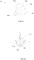
- connection joint 55 By providing the connection joint 55, the present invention can simplify the connecting process of the connecting assembly 4 and the negative pressure mechanism 5. When it needs to install the connecting assembly 4, it directly fixes the connecting assembly 4 to the second extending portion 553 of the connection joint 55.
- the flange 551 is provided with a notch 551a along a periphery, the connecting portion 511 has a protrusion 511 a extending from a wall of the fourth through-hole H4, the protrusion 511a is inserted into the notch 551a.
- the present invention can prevent the connection joint 55 rotating in the process of formation.
Landscapes
- Chemical & Material Sciences (AREA)
- Chemical Kinetics & Catalysis (AREA)
- Electrochemistry (AREA)
- General Chemical & Material Sciences (AREA)
- Engineering & Computer Science (AREA)
- Manufacturing & Machinery (AREA)
- Materials Engineering (AREA)
- Battery Mounting, Suspending (AREA)
- Sealing Battery Cases Or Jackets (AREA)
- Filling, Topping-Up Batteries (AREA)
Applications Claiming Priority (2)
| Application Number | Priority Date | Filing Date | Title |
|---|---|---|---|
| CN201921001625.4U CN209963174U (zh) | 2019-06-28 | 2019-06-28 | 电池化成装置 |
| PCT/CN2019/095245 WO2020258377A1 (zh) | 2019-06-28 | 2019-07-09 | 电池化成装置 |
Publications (4)
| Publication Number | Publication Date |
|---|---|
| EP3783726A4 EP3783726A4 (de) | 2021-02-24 |
| EP3783726A1 true EP3783726A1 (de) | 2021-02-24 |
| EP3783726C0 EP3783726C0 (de) | 2023-12-20 |
| EP3783726B1 EP3783726B1 (de) | 2023-12-20 |
Family
ID=69248739
Family Applications (1)
| Application Number | Title | Priority Date | Filing Date |
|---|---|---|---|
| EP19752910.0A Active EP3783726B1 (de) | 2019-06-28 | 2019-07-09 | Vorrichtung zur bildung von batterien |
Country Status (6)
| Country | Link |
|---|---|
| US (1) | US10971759B2 (de) |
| EP (1) | EP3783726B1 (de) |
| CN (1) | CN209963174U (de) |
| ES (1) | ES2974023T3 (de) |
| HU (1) | HUE065617T2 (de) |
| WO (1) | WO2020258377A1 (de) |
Cited By (1)
| Publication number | Priority date | Publication date | Assignee | Title |
|---|---|---|---|---|
| CN114512639A (zh) * | 2022-04-18 | 2022-05-17 | 深圳市熊利达科技有限公司 | 一种蓄电池极板化成设备及化成方法 |
Families Citing this family (6)
| Publication number | Priority date | Publication date | Assignee | Title |
|---|---|---|---|---|
| CN112164827B (zh) * | 2020-09-02 | 2021-12-10 | 珠海泰坦新动力电子有限公司 | 一种软包电池化成装置及方法 |
| KR102564225B1 (ko) | 2021-01-19 | 2023-08-07 | 주식회사 원익피앤이 | 양극 및 음극을 상면에 갖는 원통형 2차 전지 활성화를 위한 포메이션 장비 |
| CN114020060B (zh) * | 2022-01-10 | 2022-03-25 | 深圳市铂纳特斯自动化科技有限公司 | 一种电池化成设备用负压真空控制系统及其自动控制方法 |
| EP4331736A4 (de) * | 2022-07-19 | 2024-10-30 | Zhuhai Titans New Power Electronics Co., Ltd | Reinigungsverfahren und reinigungswerkzeug für unterdruckanordnung zur batteriebildung |
| CN117497890A (zh) * | 2022-07-25 | 2024-02-02 | 浙江杭可科技股份有限公司 | 一种软包电池气囊型化成探针接电机构 |
| CN116160849B (zh) * | 2023-04-26 | 2023-07-14 | 山西清亿氢能科技有限公司 | 一种新能源汽车用储氢瓶系统保护装置 |
Family Cites Families (14)
| Publication number | Priority date | Publication date | Assignee | Title |
|---|---|---|---|---|
| CN204991884U (zh) * | 2015-08-13 | 2016-01-20 | 珠海银隆新能源有限公司 | 锂离子电池化成用排气装置 |
| CN108075201B (zh) * | 2016-11-11 | 2019-11-29 | 宁德时代新能源科技股份有限公司 | 老化除气装置 |
| CN206210942U (zh) | 2016-11-16 | 2017-05-31 | 青海时代新能源科技有限公司 | 一种二次电池化成装置 |
| CN206340598U (zh) | 2016-11-30 | 2017-07-18 | 四川南都国舰新能源股份有限公司 | 一种用于内化成小密铅酸蓄电池灌酸装置 |
| CN206422143U (zh) | 2017-01-17 | 2017-08-18 | 宁德时代新能源科技股份有限公司 | 化成注液装置 |
| CN108666624B (zh) | 2017-03-31 | 2024-04-05 | 深圳市瑞能实业股份有限公司 | 电池自动化化成负压系统 |
| CN207233883U (zh) * | 2017-08-14 | 2018-04-13 | 青岛国轩电池有限公司 | 一种用于锂离子电池化成过程中的负压系统 |
| CN108808102B (zh) * | 2018-06-13 | 2020-10-30 | 桑德新能源技术开发有限公司 | 用于锂离子电池化成过程的间歇式负压调节系统和负压调节方法 |
| CN108899457B (zh) * | 2018-06-29 | 2024-05-24 | 湖南福德电气有限公司 | 一体式负压杯及其制造方法 |
| DE102018126225A1 (de) * | 2018-10-22 | 2020-04-23 | Volkswagen Aktiengesellschaft | Spannsystem für die flexible Fertigung von Lithium-Ionen Batterien |
| CN209029492U (zh) * | 2018-11-05 | 2019-06-25 | 深圳市智佳能自动化有限公司 | 一种锂电池负压杯装置 |
| CN209786130U (zh) * | 2019-06-28 | 2019-12-13 | 江苏时代新能源科技有限公司 | 电池化成装置 |
| CN112151891B (zh) * | 2019-06-28 | 2025-03-11 | 江苏时代新能源科技有限公司 | 电池化成装置 |
| CN212113922U (zh) * | 2020-05-20 | 2020-12-08 | 郑忠 | 一种锂电池组生产用填胶固定装置 |
-
2019
- 2019-06-28 CN CN201921001625.4U patent/CN209963174U/zh active Active
- 2019-07-09 WO PCT/CN2019/095245 patent/WO2020258377A1/zh not_active Ceased
- 2019-07-09 ES ES19752910T patent/ES2974023T3/es active Active
- 2019-07-09 EP EP19752910.0A patent/EP3783726B1/de active Active
- 2019-07-09 HU HUE19752910A patent/HUE065617T2/hu unknown
- 2019-08-22 US US16/548,586 patent/US10971759B2/en active Active
Cited By (2)
| Publication number | Priority date | Publication date | Assignee | Title |
|---|---|---|---|---|
| CN114512639A (zh) * | 2022-04-18 | 2022-05-17 | 深圳市熊利达科技有限公司 | 一种蓄电池极板化成设备及化成方法 |
| CN114512639B (zh) * | 2022-04-18 | 2022-06-17 | 深圳市熊利达科技有限公司 | 一种蓄电池极板化成设备及化成方法 |
Also Published As
| Publication number | Publication date |
|---|---|
| HUE065617T2 (hu) | 2024-06-28 |
| EP3783726C0 (de) | 2023-12-20 |
| WO2020258377A1 (zh) | 2020-12-30 |
| CN209963174U (zh) | 2020-01-17 |
| EP3783726B1 (de) | 2023-12-20 |
| EP3783726A4 (de) | 2021-02-24 |
| US20200411898A1 (en) | 2020-12-31 |
| ES2974023T3 (es) | 2024-06-25 |
| US10971759B2 (en) | 2021-04-06 |
Similar Documents
| Publication | Publication Date | Title |
|---|---|---|
| EP3790099B1 (de) | Vorrichtung zur batteriebildung | |
| US10971759B2 (en) | Device for battery formation | |
| CN209786130U (zh) | 电池化成装置 | |
| CN116845503A (zh) | 一种圆柱电池结构 | |
| CN212033118U (zh) | 一种锂电池用高压自动排气的电池安全阀 | |
| CN101436668A (zh) | 动力型圆柱密封锌镍碱性蓄电池集流结构 | |
| CN216161819U (zh) | 电池外壳、电池、电池模组及电池包 | |
| JP2011243404A (ja) | アルカリ二次電池及びその製造方法 | |
| CN111637227A (zh) | 一种车用电气壳体密封结构 | |
| CN118507945A (zh) | 一种新型动力电池盖板组件及制造工艺 | |
| CN210309006U (zh) | 一种机器外壳用吸塑模具的真空密封结构 | |
| CN218215498U (zh) | 一种密封组件及动力电池 | |
| CN211474286U (zh) | 一种具有变截面密封皮碗结构的活塞结构 | |
| CN213273117U (zh) | 空调器的面板组件和具有其的空调器 | |
| CN213460514U (zh) | 气箱密封装置 | |
| CN224177351U (zh) | 一种锂电池负压化成负压吸嘴装置 | |
| CN221009117U (zh) | 电池箱 | |
| CN217842630U (zh) | 一种新型轴流压缩机气体密封装置 | |
| CN224082542U (zh) | 一种碱性锌锰电池密封圈结构 | |
| CN218919010U (zh) | 一种负压化成用加酸壶 | |
| CN220849938U (zh) | 一种密封胶生产用空气压缩机 | |
| CN222732099U (zh) | 腔体密封对接连接结构 | |
| CN221347879U (zh) | 一种密封圈 | |
| CN222763065U (zh) | 一种可在外部焊接集流体的方形电池盖板 | |
| CN223854999U (zh) | 一种流量控制活门阀轴的密封工装 |
Legal Events
| Date | Code | Title | Description |
|---|---|---|---|
| STAA | Information on the status of an ep patent application or granted ep patent |
Free format text: STATUS: UNKNOWN |
|
| STAA | Information on the status of an ep patent application or granted ep patent |
Free format text: STATUS: THE INTERNATIONAL PUBLICATION HAS BEEN MADE |
|
| PUAI | Public reference made under article 153(3) epc to a published international application that has entered the european phase |
Free format text: ORIGINAL CODE: 0009012 |
|
| STAA | Information on the status of an ep patent application or granted ep patent |
Free format text: STATUS: REQUEST FOR EXAMINATION WAS MADE |
|
| 17P | Request for examination filed |
Effective date: 20190822 |
|
| A4 | Supplementary search report drawn up and despatched |
Effective date: 20201123 |
|
| AK | Designated contracting states |
Kind code of ref document: A1 Designated state(s): AL AT BE BG CH CY CZ DE DK EE ES FI FR GB GR HR HU IE IS IT LI LT LU LV MC MK MT NL NO PL PT RO RS SE SI SK SM TR |
|
| AX | Request for extension of the european patent |
Extension state: BA ME |
|
| STAA | Information on the status of an ep patent application or granted ep patent |
Free format text: STATUS: EXAMINATION IS IN PROGRESS |
|
| 17Q | First examination report despatched |
Effective date: 20210707 |
|
| DAV | Request for validation of the european patent (deleted) | ||
| DAX | Request for extension of the european patent (deleted) | ||
| REG | Reference to a national code |
Ref country code: DE Ref legal event code: R079 Free format text: PREVIOUS MAIN CLASS: H01M0010440000 Ipc: H01M0010520000 Ref country code: DE Ref legal event code: R079 Ref document number: 602019043609 Country of ref document: DE Free format text: PREVIOUS MAIN CLASS: H01M0010440000 Ipc: H01M0010520000 |
|
| RIC1 | Information provided on ipc code assigned before grant |
Ipc: H01M 10/04 20060101ALI20230515BHEP Ipc: H01M 50/30 20210101ALI20230515BHEP Ipc: H01M 10/52 20060101AFI20230515BHEP |
|
| GRAP | Despatch of communication of intention to grant a patent |
Free format text: ORIGINAL CODE: EPIDOSNIGR1 |
|
| STAA | Information on the status of an ep patent application or granted ep patent |
Free format text: STATUS: GRANT OF PATENT IS INTENDED |
|
| INTG | Intention to grant announced |
Effective date: 20230703 |
|
| GRAS | Grant fee paid |
Free format text: ORIGINAL CODE: EPIDOSNIGR3 |
|
| GRAA | (expected) grant |
Free format text: ORIGINAL CODE: 0009210 |
|
| STAA | Information on the status of an ep patent application or granted ep patent |
Free format text: STATUS: THE PATENT HAS BEEN GRANTED |
|
| AK | Designated contracting states |
Kind code of ref document: B1 Designated state(s): AL AT BE BG CH CY CZ DE DK EE ES FI FR GB GR HR HU IE IS IT LI LT LU LV MC MK MT NL NO PL PT RO RS SE SI SK SM TR |
|
| REG | Reference to a national code |
Ref country code: GB Ref legal event code: FG4D |
|
| REG | Reference to a national code |
Ref country code: CH Ref legal event code: EP |
|
| REG | Reference to a national code |
Ref country code: DE Ref legal event code: R096 Ref document number: 602019043609 Country of ref document: DE |
|
| REG | Reference to a national code |
Ref country code: IE Ref legal event code: FG4D |
|
| U01 | Request for unitary effect filed |
Effective date: 20240116 |
|
| U07 | Unitary effect registered |
Designated state(s): AT BE BG DE DK EE FI FR IT LT LU LV MT NL PT SE SI Effective date: 20240125 |
|
| PG25 | Lapsed in a contracting state [announced via postgrant information from national office to epo] |
Ref country code: GR Free format text: LAPSE BECAUSE OF FAILURE TO SUBMIT A TRANSLATION OF THE DESCRIPTION OR TO PAY THE FEE WITHIN THE PRESCRIBED TIME-LIMIT Effective date: 20240321 |
|
| PG25 | Lapsed in a contracting state [announced via postgrant information from national office to epo] |
Ref country code: GR Free format text: LAPSE BECAUSE OF FAILURE TO SUBMIT A TRANSLATION OF THE DESCRIPTION OR TO PAY THE FEE WITHIN THE PRESCRIBED TIME-LIMIT Effective date: 20240321 |
|
| PG25 | Lapsed in a contracting state [announced via postgrant information from national office to epo] |
Ref country code: RS Free format text: LAPSE BECAUSE OF FAILURE TO SUBMIT A TRANSLATION OF THE DESCRIPTION OR TO PAY THE FEE WITHIN THE PRESCRIBED TIME-LIMIT Effective date: 20231220 Ref country code: NO Free format text: LAPSE BECAUSE OF FAILURE TO SUBMIT A TRANSLATION OF THE DESCRIPTION OR TO PAY THE FEE WITHIN THE PRESCRIBED TIME-LIMIT Effective date: 20240320 Ref country code: HR Free format text: LAPSE BECAUSE OF FAILURE TO SUBMIT A TRANSLATION OF THE DESCRIPTION OR TO PAY THE FEE WITHIN THE PRESCRIBED TIME-LIMIT Effective date: 20231220 |
|
| REG | Reference to a national code |
Ref country code: ES Ref legal event code: FG2A Ref document number: 2974023 Country of ref document: ES Kind code of ref document: T3 Effective date: 20240625 |
|
| REG | Reference to a national code |
Ref country code: HU Ref legal event code: AG4A Ref document number: E065617 Country of ref document: HU |
|
| PG25 | Lapsed in a contracting state [announced via postgrant information from national office to epo] |
Ref country code: IS Free format text: LAPSE BECAUSE OF FAILURE TO SUBMIT A TRANSLATION OF THE DESCRIPTION OR TO PAY THE FEE WITHIN THE PRESCRIBED TIME-LIMIT Effective date: 20240420 |
|
| PG25 | Lapsed in a contracting state [announced via postgrant information from national office to epo] |
Ref country code: CZ Free format text: LAPSE BECAUSE OF FAILURE TO SUBMIT A TRANSLATION OF THE DESCRIPTION OR TO PAY THE FEE WITHIN THE PRESCRIBED TIME-LIMIT Effective date: 20231220 |
|
| PG25 | Lapsed in a contracting state [announced via postgrant information from national office to epo] |
Ref country code: SK Free format text: LAPSE BECAUSE OF FAILURE TO SUBMIT A TRANSLATION OF THE DESCRIPTION OR TO PAY THE FEE WITHIN THE PRESCRIBED TIME-LIMIT Effective date: 20231220 |
|
| PG25 | Lapsed in a contracting state [announced via postgrant information from national office to epo] |
Ref country code: SM Free format text: LAPSE BECAUSE OF FAILURE TO SUBMIT A TRANSLATION OF THE DESCRIPTION OR TO PAY THE FEE WITHIN THE PRESCRIBED TIME-LIMIT Effective date: 20231220 Ref country code: SK Free format text: LAPSE BECAUSE OF FAILURE TO SUBMIT A TRANSLATION OF THE DESCRIPTION OR TO PAY THE FEE WITHIN THE PRESCRIBED TIME-LIMIT Effective date: 20231220 Ref country code: RO Free format text: LAPSE BECAUSE OF FAILURE TO SUBMIT A TRANSLATION OF THE DESCRIPTION OR TO PAY THE FEE WITHIN THE PRESCRIBED TIME-LIMIT Effective date: 20231220 Ref country code: IS Free format text: LAPSE BECAUSE OF FAILURE TO SUBMIT A TRANSLATION OF THE DESCRIPTION OR TO PAY THE FEE WITHIN THE PRESCRIBED TIME-LIMIT Effective date: 20240420 Ref country code: CZ Free format text: LAPSE BECAUSE OF FAILURE TO SUBMIT A TRANSLATION OF THE DESCRIPTION OR TO PAY THE FEE WITHIN THE PRESCRIBED TIME-LIMIT Effective date: 20231220 |
|
| PG25 | Lapsed in a contracting state [announced via postgrant information from national office to epo] |
Ref country code: PL Free format text: LAPSE BECAUSE OF FAILURE TO SUBMIT A TRANSLATION OF THE DESCRIPTION OR TO PAY THE FEE WITHIN THE PRESCRIBED TIME-LIMIT Effective date: 20231220 |
|
| U20 | Renewal fee for the european patent with unitary effect paid |
Year of fee payment: 6 Effective date: 20240723 |
|
| PG25 | Lapsed in a contracting state [announced via postgrant information from national office to epo] |
Ref country code: PL Free format text: LAPSE BECAUSE OF FAILURE TO SUBMIT A TRANSLATION OF THE DESCRIPTION OR TO PAY THE FEE WITHIN THE PRESCRIBED TIME-LIMIT Effective date: 20231220 |
|
| REG | Reference to a national code |
Ref country code: DE Ref legal event code: R097 Ref document number: 602019043609 Country of ref document: DE |
|
| PLBE | No opposition filed within time limit |
Free format text: ORIGINAL CODE: 0009261 |
|
| STAA | Information on the status of an ep patent application or granted ep patent |
Free format text: STATUS: NO OPPOSITION FILED WITHIN TIME LIMIT |
|
| 26N | No opposition filed |
Effective date: 20240923 |
|
| PG25 | Lapsed in a contracting state [announced via postgrant information from national office to epo] |
Ref country code: MC Free format text: LAPSE BECAUSE OF FAILURE TO SUBMIT A TRANSLATION OF THE DESCRIPTION OR TO PAY THE FEE WITHIN THE PRESCRIBED TIME-LIMIT Effective date: 20231220 |
|
| REG | Reference to a national code |
Ref country code: CH Ref legal event code: PL |
|
| PG25 | Lapsed in a contracting state [announced via postgrant information from national office to epo] |
Ref country code: CH Free format text: LAPSE BECAUSE OF NON-PAYMENT OF DUE FEES Effective date: 20240731 |
|
| PG25 | Lapsed in a contracting state [announced via postgrant information from national office to epo] |
Ref country code: IE Free format text: LAPSE BECAUSE OF NON-PAYMENT OF DUE FEES Effective date: 20240709 |
|
| PGFP | Annual fee paid to national office [announced via postgrant information from national office to epo] |
Ref country code: HU Payment date: 20250702 Year of fee payment: 7 |
|
| U20 | Renewal fee for the european patent with unitary effect paid |
Year of fee payment: 7 Effective date: 20250722 |
|
| PGFP | Annual fee paid to national office [announced via postgrant information from national office to epo] |
Ref country code: ES Payment date: 20250801 Year of fee payment: 7 |
|
| PGFP | Annual fee paid to national office [announced via postgrant information from national office to epo] |
Ref country code: GB Payment date: 20250722 Year of fee payment: 7 |
|
| PG25 | Lapsed in a contracting state [announced via postgrant information from national office to epo] |
Ref country code: CY Free format text: LAPSE BECAUSE OF FAILURE TO SUBMIT A TRANSLATION OF THE DESCRIPTION OR TO PAY THE FEE WITHIN THE PRESCRIBED TIME-LIMIT; INVALID AB INITIO Effective date: 20190709 |