EP3783738B1 - Élargissement de faisceau à large bande pour des systèmes d'antenne réseau à commande de phase - Google Patents
Élargissement de faisceau à large bande pour des systèmes d'antenne réseau à commande de phase Download PDFInfo
- Publication number
- EP3783738B1 EP3783738B1 EP20192503.9A EP20192503A EP3783738B1 EP 3783738 B1 EP3783738 B1 EP 3783738B1 EP 20192503 A EP20192503 A EP 20192503A EP 3783738 B1 EP3783738 B1 EP 3783738B1
- Authority
- EP
- European Patent Office
- Prior art keywords
- radiation pattern
- radiating elements
- mpaa
- array
- radiating
- Prior art date
- Legal status (The legal status is an assumption and is not a legal conclusion. Google has not performed a legal analysis and makes no representation as to the accuracy of the status listed.)
- Active
Links
Images






Classifications
-
- H—ELECTRICITY
- H01—ELECTRIC ELEMENTS
- H01Q—ANTENNAS, i.e. RADIO AERIALS
- H01Q25/00—Antennas or antenna systems providing at least two radiating patterns
- H01Q25/04—Multimode antennas
-
- H—ELECTRICITY
- H01—ELECTRIC ELEMENTS
- H01Q—ANTENNAS, i.e. RADIO AERIALS
- H01Q3/00—Arrangements for changing or varying the orientation or the shape of the directional pattern of the waves radiated from an antenna or antenna system
- H01Q3/26—Arrangements for changing or varying the orientation or the shape of the directional pattern of the waves radiated from an antenna or antenna system varying the relative phase or relative amplitude of energisation between two or more active radiating elements; varying the distribution of energy across a radiating aperture
- H01Q3/30—Arrangements for changing or varying the orientation or the shape of the directional pattern of the waves radiated from an antenna or antenna system varying the relative phase or relative amplitude of energisation between two or more active radiating elements; varying the distribution of energy across a radiating aperture varying the relative phase between the radiating elements of an array
- H01Q3/34—Arrangements for changing or varying the orientation or the shape of the directional pattern of the waves radiated from an antenna or antenna system varying the relative phase or relative amplitude of energisation between two or more active radiating elements; varying the distribution of energy across a radiating aperture varying the relative phase between the radiating elements of an array by electrical means
- H01Q3/36—Arrangements for changing or varying the orientation or the shape of the directional pattern of the waves radiated from an antenna or antenna system varying the relative phase or relative amplitude of energisation between two or more active radiating elements; varying the distribution of energy across a radiating aperture varying the relative phase between the radiating elements of an array by electrical means with variable phase-shifters
-
- H—ELECTRICITY
- H01—ELECTRIC ELEMENTS
- H01Q—ANTENNAS, i.e. RADIO AERIALS
- H01Q21/00—Antenna arrays or systems
- H01Q21/06—Arrays of individually energised antenna units similarly polarised and spaced apart
- H01Q21/061—Two dimensional planar arrays
-
- H—ELECTRICITY
- H01—ELECTRIC ELEMENTS
- H01Q—ANTENNAS, i.e. RADIO AERIALS
- H01Q21/00—Antenna arrays or systems
- H01Q21/06—Arrays of individually energised antenna units similarly polarised and spaced apart
- H01Q21/061—Two dimensional planar arrays
- H01Q21/065—Patch antenna array
-
- H—ELECTRICITY
- H01—ELECTRIC ELEMENTS
- H01Q—ANTENNAS, i.e. RADIO AERIALS
- H01Q21/00—Antenna arrays or systems
- H01Q21/06—Arrays of individually energised antenna units similarly polarised and spaced apart
- H01Q21/08—Arrays of individually energised antenna units similarly polarised and spaced apart the units being spaced along or adjacent to a rectilinear path
-
- H—ELECTRICITY
- H01—ELECTRIC ELEMENTS
- H01Q—ANTENNAS, i.e. RADIO AERIALS
- H01Q25/00—Antennas or antenna systems providing at least two radiating patterns
- H01Q25/002—Antennas or antenna systems providing at least two radiating patterns providing at least two patterns of different beamwidth; Variable beamwidth antennas
-
- H—ELECTRICITY
- H01—ELECTRIC ELEMENTS
- H01Q—ANTENNAS, i.e. RADIO AERIALS
- H01Q3/00—Arrangements for changing or varying the orientation or the shape of the directional pattern of the waves radiated from an antenna or antenna system
- H01Q3/24—Arrangements for changing or varying the orientation or the shape of the directional pattern of the waves radiated from an antenna or antenna system varying the orientation by switching energy from one active radiating element to another, e.g. for beam switching
-
- G—PHYSICS
- G01—MEASURING; TESTING
- G01S—RADIO DIRECTION-FINDING; RADIO NAVIGATION; DETERMINING DISTANCE OR VELOCITY BY USE OF RADIO WAVES; LOCATING OR PRESENCE-DETECTING BY USE OF THE REFLECTION OR RERADIATION OF RADIO WAVES; ANALOGOUS ARRANGEMENTS USING OTHER WAVES
- G01S13/00—Systems using the reflection or reradiation of radio waves, e.g. radar systems; Analogous systems using reflection or reradiation of waves whose nature or wavelength is irrelevant or unspecified
- G01S13/02—Systems using reflection of radio waves, e.g. primary radar systems; Analogous systems
- G01S2013/0236—Special technical features
- G01S2013/0245—Radar with phased array antenna
- G01S2013/0263—Passive array antenna
-
- H—ELECTRICITY
- H01—ELECTRIC ELEMENTS
- H01Q—ANTENNAS, i.e. RADIO AERIALS
- H01Q21/00—Antenna arrays or systems
- H01Q21/0006—Particular feeding systems
- H01Q21/0025—Modular arrays
-
- H—ELECTRICITY
- H01—ELECTRIC ELEMENTS
- H01Q—ANTENNAS, i.e. RADIO AERIALS
- H01Q21/00—Antenna arrays or systems
- H01Q21/06—Arrays of individually energised antenna units similarly polarised and spaced apart
-
- H—ELECTRICITY
- H01—ELECTRIC ELEMENTS
- H01Q—ANTENNAS, i.e. RADIO AERIALS
- H01Q21/00—Antenna arrays or systems
- H01Q21/06—Arrays of individually energised antenna units similarly polarised and spaced apart
- H01Q21/22—Antenna units of the array energised non-uniformly in amplitude or phase, e.g. tapered array or binomial array
-
- H—ELECTRICITY
- H01—ELECTRIC ELEMENTS
- H01Q—ANTENNAS, i.e. RADIO AERIALS
- H01Q3/00—Arrangements for changing or varying the orientation or the shape of the directional pattern of the waves radiated from an antenna or antenna system
- H01Q3/26—Arrangements for changing or varying the orientation or the shape of the directional pattern of the waves radiated from an antenna or antenna system varying the relative phase or relative amplitude of energisation between two or more active radiating elements; varying the distribution of energy across a radiating aperture
Definitions
- Patent document US 2013/321207 A1 states: a method and apparatus for transforming signals for wireless communication.
- the apparatus includes a transformer comprising a plurality of first ports and second ports. Each first port is associated with a mode of a first antenna array configuration and each second port is configurable to be communicatively coupled to one of the antennas deployed in the first antenna array configuration. It includes a selector configurable to select a subset of the modes of the first antenna array configuration based on a degree of variation with azimuth. It further includes a mapper configured to map each of a plurality of third ports to one of the first ports associated with one of the subset of modes. Each of the third ports is associated with a mode of a second antenna array configuration.
- Patent document US 6 218 987 B1 states: an apparatus and a method for generating, with the same radio antenna apparatus, a number of narrow beams and a wide beam, covering substantially the same area covered by the individual pointed beams together.
- the radio antenna apparatus comprises an antenna array a Butler matrix connected to the antenna array and a set of amplifying modules.
- the activation of each of the inputs of the radio antenna apparatus corresponds to a radiation pattern characterized by a narrow beam with a high antenna gain from the antenna array.
- the present disclosure provides a multi-mode phased array antenna ("MPAA”) according to claim 1, and a method for widening a main-beam of a first radiation pattern produced by an MPAA according to claim 10.
- MPAA multi-mode phased array antenna
- a multi-mode phased array antenna (“MPAA”) is disclosed.
- the claimed MPAA has at least two modes of operation, where a first mode of operation produces a first radiation pattern having a main-beam and wherein a second mode of operation produces a second radiation pattern having a second beam.
- the MPAA includes a plurality of radiating elements positioned about a center point in a linear array, a rectangular array, or a planar array with a triangular lattice and a controller in signal communication with the plurality of radiating elements.
- the controller is configured to excite the plurality of radiating elements to produce the first radiation pattern having the main-beam in the first mode of operation, wherein the main-beam is substantially symmetric about a radiation axis oriented through the center point, and wherein the main-beam is directed substantially in a first direction along the radiation axis, and the second radiation pattern having the second beam in the second mode of operation.
- the second beam is wider than the main-beam and is directed substantially in a radial direction from the center point, and the second beam defines a substantially cardioid or spherical shaped pattern symmetric about the radiation axis when represented using a polar plot.
- the controller is also configured to switch between at least the first mode of operation and the second mode of operation.
- the controller is also configured to excite the plurality of radiating elements by determining a plurality of excitation signals for the plurality of radiating elements, and the plurality of excitation signals are determined based on a truncated regular series expansion of Bessel functions for an electromagnetic ("EM") field.
- EM electromagnetic
- the MPAA performs the method for widening the main-beam of the first radiation pattern.
- the method includes exciting the plurality of radiating elements to produce the second radiation pattern, where the second radiation pattern has the second beam that is wider than the main-beam and is directed substantially in a radial direction from the center point, and wherein the second beam defines a substantially cardioid or spherical shaped pattern symmetric about a radiation axis oriented through the center point when represented using a polar plot.
- Exciting the plurality of radiating elements includes determining a plurality of excitation signals for the plurality of radiating elements, and the plurality of excitation signals are determined based on a truncated regular series expansion of Bessel functions for an electromagnetic ("EM") field.
- EM electromagnetic
- the present disclosure comprises the following examples.
- a multi-mode phased array antenna has at least two modes of operation, wherein a first mode of operation produces a first radiation pattern having a main-beam and a second mode of operation produces a second radiation pattern having a second beam
- the MPAA comprising a plurality of radiating elements arranged as an array of radiating elements, and a controller in signal communication with the plurality of radiating elements, wherein the controller is configured to excite the plurality of radiating elements to produce the first radiation pattern having the main-beam in the first mode of operation and the second radiation pattern having the second beam in the second mode of operation, wherein the second beam is wider than the main-beam, and wherein the second radiation pattern is similar to a radiation pattern of a single radiating element of the plurality of radiating elements and wherein the controller is also configured to switch between the first mode operation and the second mode of operation.
- the array of radiating elements has an array center, and wherein the second radiation pattern is approximately an amplified radiation pattern of a single radiating element that is located at the array center.
- the single radiating element has an approximate constant directivity and an approximate omnidirectional far-field radiation pattern.
- the plurality of radiating elements has an array factor and wherein the array factor has an approximately constant gain.
- each radiating element of the plurality of radiating elements has a corresponding radiating element radiation pattern and wherein a summation of all of the radiating element radiation patterns of each radiating element of the plurality of radiating elements results in the second radiation pattern.
- each radiating element of the plurality of radiating elements is a transmit/receive (“T/R”) module.
- each radiating element of the plurality of radiating elements has a corresponding element vector that includes a radiation pattern and polarization for the radiating element.
- the controller is configured to excite the plurality of radiating elements by determining a plurality of excitation signals for the plurality of radiating elements and wherein the plurality of excitation signals are determined by utilizing a truncated regular series expansion of Bessel functions for an electromagnetic ("EM") field of the single radiating element and preferably equating the truncated regular series expansion of Bessel functions for EM field to an array response for the MPAA.
- EM electromagnetic
- the plurality of radiating elements comprises an array of radiating element having an array center positioned at the center point, preferably wherein each of the plurality of radiating elements are equidistant from the array center; and wherein the second radiation pattern is representative of an amplified radiation pattern of a single radiating element located at the array center.
- the controller is further configured to determine an array factor to produce the second radiation pattern, and wherein the array factor has a substantially constant gain.
- the second excitation of the plurality of radiating elements includes determining a plurality of excitation signals for the plurality of radiating elements, and wherein the plurality of excitation signals are determined based on a truncated regular series expansion of Bessel functions for an electromagnetic ("EM") field.
- EM electromagnetic
- the Bessel functions comprise Bessel functions of the first kind of an order i, wherein i is an integer, and wherein the regular series is a Laurent series.
- the Bessel functions comprise Bessel functions of the first kind of an order i, corresponding to radiating element distances in wavelength from the center point.
- the MPAA performs a method for widening the main-beam of the first radiation pattern.
- the method includes exciting the plurality of radiating elements to produce the second radiation pattern, where the second radiation pattern is similar to the radiation pattern of a single radiating element of the plurality of radiating elements and where the second radiation pattern has the second beam that is wider than the main-beam.
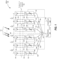
- the MPAA 100 includes a plurality of radiating elements 102 arranged as an array of radiating elements that may be linear (i.e., one-dimensional), planar (i.e., two-dimensional), or conformal (i.e., three-dimensional) and a controller 104 in signal communication with the plurality of radiating elements 102 via signal path 106.
- a controller 104 in signal communication with the plurality of radiating elements 102 via signal path 106.
- the signal path 106 may be a signal bus (e.g., computer bus) that is in signal communication with each radiating element 108, 110, 112, 114, 116, and 118 (also known as “array radiating elements” or “array elements”), respectively, of the plurality of radiating elements 102.
- a signal bus e.g., computer bus
- each radiating element 108, 110, 112, 114, 116, and 118 may be controlled in spectrum, timing, amplitude and phase via the controller 104, where each radiating element 108, 110, 112, 114, 116, and 118 includes e.g., a phase-shifter 120, 124, 128, 132, 136, and 140 and e.g., an attenuator 122, 126, 130, 134, 138, and 142, respectively.
- each radiating element 108, 110, 112, 114, 116, and 118 is in signal communication with a combiner/feed network 156 via signal paths 158, 160, 162, 164, 166, and 168, respectively.
- a transceiver 170 may also be in signal communication with both the combiner/feed network 156 and controller 104 via signal paths 172 and 174, respectively.
- each radiating element 108, 110, 112, 114, 116, and 118 may be a transmit/receive ("T/R") module.
- each of the radiating elements may include an individual radiator 176, 178, 180, 182, 184, and 186 which may be, for example, a dipole, aperture, patch, or other type of individual antenna radiating element.
- circuits, components, modules, and/or devices of, or associated with, the MPAA 100, radiating element 108, 110, 112, 114, 116, and 118, and controller 104 are described as being in signal communication with each other, where signal communication refers to any type of communication and/or connection between the circuits, components, modules, and/or devices that allows a circuit, component, module, and/or device to pass and/or receive signals and/or information from another circuit, component, module, and/or device.
- the communication and/or connection may be along any signal path between the circuits, components, modules, and/or devices that allows signals and/or information to pass from one circuit, component, module, and/or device to another and includes wireless or wired signal paths.
- the signal paths may be physical, such as, for example, conductive wires, electromagnetic wave guides, optical fibers, cables, attached and/or electromagnetic or mechanically coupled terminals, semi-conductive or dielectric materials or devices, or other similar physical connections or couplings. Additionally, signal paths may be non-physical such as free-space (in the case of electromagnetic propagation) or information paths through digital components where communication information is passed from one circuit, component, module, and/or device to another in varying digital formats without passing through a direct electromagnetic connection.
- the plurality of radiating elements 102 has an array center 188 that corresponds to the physical center of the plurality of radiating elements 102 where each radiating element pair (i.e., 108 and 110, 110 and 112, 112 and 114, 114 and 116, and 116 and 118) of the plurality of radiating elements 102 is spaced apart by an inter-radiating element distance 190 (referred to here as " d " 190) the same amount (i.e., an equally spaced array).
- the array center 188 is shown at the half-way distance (i.e., half of between the two radiating elements 112 and 114).
- Typical lengths for the spacing d 190 may include, for example, a quarter, a half, and a full wavelength of operation which corresponds to a center-frequency of operation of the MPAA 100.
- Typical lengths for the spacing d 190 may include, for example, a quarter, a half, and a full wavelength of operation which corresponds to a center-frequency of operation of the MPAA 100.
- only six (6) radiating elements 108, 110, 112, 114, 116, and 118 are shown in the plurality of radiating elements 102 for the purpose of ease of illustration; however, the actual number of radiating elements may be less than, more, or significantly more than six based on the design of the MPAA 100, furthermore the radiating elements do not necessarily need to be equispaced.
- the MPAA 100 may include more than a thousand radiating elements in some designs where the spacing between some of the elements may not necessarily be similar due to design (e.g., sparsely populated antenna array such as, for example, a mimimum reducndancy linear arrays ("MRLA”)) or mechanical constraints such as mounting supports.
- MRLA mimimum reducndancy linear arrays
- the beam-width i.e., the width of the main-beam
- first nulls i.e., the areas of the radiation pattern where the array factor first goes to zero on both the positive and negative sides of the main-lobe
- BWFN first nulls
- 2x two-times
- the wavelength of operation divided by the product of the total number of radiating elements (of the plurality of radiating elements 102) and the spacing d 190 between the radiating elements.
- the BWFN is related to the wavelength (" ⁇ ") of operation, number of radiating elements (" N ") of the plurality of radiating elements 102, and spacing d 190 as follows: BWFN ⁇ 2 ⁇ Nd .
- FIG. 2 a top-view of an example of an implementation of an example of a linear (i.e., one-dimensional) MPAA 200 is shown.
- the MPAA 200 includes six (6) radiating elements 202(1), 202(2), 202(3), 202(4), 202(5), and 202(6) along a Y -axis 204 in a X-Y plane 206 defined by the Y -axis 204 and an X -axis 208.
- radiating elements 202(1), 202(2), 202(3), 202(4), 202(5), and 202(6) are shown for the purpose of illustration but it is appreciated by those of ordinary skill in the art that the number radiating elements may vary from two to a large number (e.g., greater than a 1,000). In this example, all of the radiating elements 202(1), 202(2), 202(3), 202(4), 202(5), and 202(6) are equidistant spaced apart by the inter-element distance d 190 as described in relation to FIG. 1 .
- the MPAA 200 may direct its radiation in a broadside direction along a Z- axis 210 out of the X-Y plane 206 in a positive direction, in a negative direction into the X-Y plane 206, or along either the negative or positive directions of the Y -axis 204.
- the MPAA 200 is configured to direct its radiation pattern in the broadside direction along the positive direction of the Z -axis 210.
- the resulting radiation pattern will be scanned along an azimuth angle ⁇ 212 between the X -axis 208 and Y -axis 204 and an elevation angle ⁇ (not shown) along the Y -axis 204 and Z -axis 210.
- all of the radiating elements 300(1) through 300(36) are equidistant spaced apart by the inter-element distance d 190 along both the X -axis 218 and Y- axis 214. It is appreciated that that inter-element distance may also optionally be unequal the X -axis 218 or along the Y -axis 214 to realize sparsely populated antenna array; however, for the purposes of simplicity the inter-element distance spacing in both the X -axis 218 and Y -axis 214 directions have been set to the same value equal to d 190.
- each individual radiating element 202(1) through 202(6) or 300(1) through 300(36) may be either, or part of, a T/R module (as shown in FIG. 1 ) where each T/R module includes, inter alia, a phase-shifter and a power amplifier.
- the polar plot 400 includes a main-lobe 402 along a Z -axis 404 in the positive direction, a back-lobe 406 along Z -axis 404 in a negative direction, and side-lobes 408, 410, 412, and 414 along a positive and negative direction of a Y -axis 416 and angles between the X and Y axis 404 and 416.
- the main-lobe 402, back-lobe 406, and side-lobes 408, 410, 412, and 414 are spaced apart along a scanning angle ⁇ 418 (i.e., the polar angle also known as the elevation angle) along an X-Y plane 420 defined by the Z -axis 404 and Y -axis 416.
- a scanning angle ⁇ 418 i.e., the polar angle also known as the elevation angle
- the antenna in a transmitting mode, has high directivity because most of the radiating energy is transmitted along the positive direction of the Z -axis 404 (herein referred to ⁇ scanning angles 418 between, for example, -30 to 30 degrees from a reference 0 degrees scanning angles ⁇ 418 along the positive direction of the Z -axis 404) within the main-lobe 402 while only small portions of energy are radiated out in the other directions (i.e., other angles ⁇ 418) covered by the back-lobe 406, and four side-lobes 408, 410, and 412.
- the far-field radiation pattern shown in this example may be the far-field radiation pattern for an antenna that may be an individual antenna element or an antenna array based on the design of the antenna.
- the MPAA 100 may optionally produce a far-field radiation pattern that has a polar plot that is approximately similar to the polar plot 400 based on the predetermined design parameters of the MPAA 100 that include, for example, the number of radiating elements, the spacing between the radiating elements, the type of radiating elements, and the amplitude and phase taper utilized to excited the radiating elements.
- the far-field radiation pattern may the first radiation pattern having the main-beam 402 in the first mode of operation of the MPAA 100.
- FIG. 4B a rectangular plot 422 of the polar plot 400 of the far-field radiation pattern is shown.
- the rectangular plot 418 is a two-dimensional plot cut along the X-Y plane 420 showing the magnitudes (along an amplitude axis 424 in decibels ("dBs")) of the main-lobe 402, back-lobe 406, and four side-lobes 408, 410, and 412 along the scanning angle ⁇ 418.
- dBs decibels
- the main-lobe 402 has beam-width 426 defined as the distance between the -3db points (along the plus an minus directions of the scan angle 418) where the -3db points represent the half radiated energy points in relation to the maximum energy radiated at point 426 corresponding to the scanning angle ⁇ 418 be at broadside (i.e., the equals 0 degrees or radians).
- the back-lobe 406 may be about -16dB and the side-lobes 408, 410, and 412 may be - 30 dB or greater; however, it is appreciated that these values are purely examples and could vary significantly based on any utilization of excitation tapers and type, structure and configuration of the antenna. It is also appreciated that in this disclosure the terms "main-lobe” and “main-beams” may be utilized interchangeable.
- FIG. 5A a plot of an example of an implementation of a polar plot 500 of a far-field radiation pattern for an isotropic antenna radiator 502 (also known as an "isotropic radiator” or “point source”) is shown.
- the polar plot 500 does not include a main-lobe but instead radiates the same intensity of radiation in all directions.
- an isotropic antenna radiator 502 is a theoretical point source of electromagnetic energy that has no preferred direction of radiation. By definition, the isotropic antenna radiator 502 radiates uniformly in all directions over a sphere centered on the isotropic antenna radiator 502.
- isotropic antenna radiators are used as reference radiators with which other antenna radiators are compared, for example in determining the gain of an antenna.
- the isotropic antenna radiator 202 is said to have a directivity of 0 dB in all directions. Similar to the example of FIG. 4A , the polar plot 500 that rotates through the scanning angle ⁇ 418 between, for example, 0 to 360 degrees from the reference 0 degrees scanning angle ⁇ 418 along the X-Y plane 420 defined by the Z- axis 404 and Y -axis 416.
- FIG. 5B a rectangular plot 504 of the polar plot 500 of the far-field radiation pattern shown in FIG. 5A .
- the rectangular plot 504 is a two-dimensional plot cut along the X-Y plane 420 showing the magnitude (along the amplitude axis 424) of the far-field radiation pattern of the polar plot 500.
- the magnitude of the rectangular plot 504 of the far-field radiation pattern of the polar plot 500 is constant 506 for all the scanning angles ⁇ 418 from angle 0 degrees 508 to -180 degrees 510 and 0 degrees 508 to 180 degrees 512.
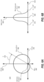
- FIG. 6A a plot of an example of an implementation of a polar plot 600 of a far-field radiation pattern of an antenna element 602 is shown in accordance with the present disclosure. Similar to the example in FIG. 5A , the polar plot 600 does not include a main-lobe but instead radiates a cardioid intensity of radiation where most of the radiation radiated to the front of antenna element 602 in the positive Z -axis 404 at the scanning angle ⁇ 418 equal to 0 degrees.
- the radiation pattern then gradually drops off from 0 dB to range of, for example, approximately -3 dB to approximately -6 dB from scanning angle ⁇ 418 from angle 0 degrees to -90 degrees and 0 degrees to 90 degrees along the negative or positive direction on the Y -axis 416.
- the radiation pattern then quickly drops off from scanning angles ⁇ 418 from angle -90 degrees to -180 degrees and 90 degrees to 180 degrees where at -180 (or 180 since it is the same scanning angle ⁇ 418) the polar plot 600 radiation pattern drops to a null 604.
- the polar plot 600 radiation pattern drops to a null 604.
- the polar plot 600 of the far-field radiation pattern of the antenna element 602 shows that the far-field radiation pattern has low directivity from the reference 0 degrees scanning angle ⁇ 418 along the X-Y plane 420 defined by the Z -axis 404 and Y -axis 416.
- FIG. 6B a rectangular plot 606 of the polar plot 600 of the far-field radiation pattern shown in FIG. 6A in accordance with the present disclosure.
- the rectangular plot 606 is a two-dimensional plot cut along the X-Y plane 420 showing the magnitude (along the amplitude axis 424) of the far-field radiation pattern of the polar plot 600.
- the magnitude of the rectangular plot 606 of the far-field radiation pattern of the polar plot 600 is approximately a sine wave between the scanning angle ⁇ 418 from angle 0 degrees 608 to -180 degrees 610 and 0 degrees 608 to 180 degrees 612.
- the polar plot 600 of the far-field radiation pattern of the antenna element 602 may be, for example, a microstrip antenna such as, for example, a patch antenna.
- the patch antenna may be about 25 millimeters ("mm") square on an approximately 70 to 100 mm ground plane square.
- the MPAA 100 may optionally produce a far-field radiation pattern that has a polar plot that is approximately similar to the polar plot 600 based on the predetermined design parameters of the MPAA 100 that again include, for example, the number of radiating elements, the spacing between the radiating elements, the type of radiating elements, and the amplitude and phase taper utilized to excited the radiating elements.
- the far-field radiation pattern may the second radiation pattern having the second beam that is approximately similar to the far-field radiation pattern of the polar plot 600 in the second mode of operation of the MPAA 100.
- each element 108, 110, 112, 114, 116, and 118 in addition to the spectrum, timing, amplitude and phase control imposed on each element 108, 110, 112, 114, 116, and 118 by the controller 104, there is a relative phase-shift between the RF energy waves 192 arriving at the elements 108, 110, 112, 114, 116, and 118 due to their positions in space and the angle of arrival of the RF energy wave 192.
- the far-field radiation pattern of each element 108, 110, 112, 114, 116, and 118 leads to a response that varies with the arrival angle of the incoming plane wave (i.e., RF energy waves 192).
- the net summation of all the plurality of elements 108, 110, 112, 114, 116, and 118 results in a constant gain curve radiation pattern similar to the single element. It is appreciated that the method may also utilize this technique generally for elements that are non-isotropic radiators.
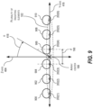
- FIG. 7 a graphical illustration of an example observation point 700 is shown in reference to a plurality of radiating elements 702, 704, 706, 708, and 710 in a MPAA 712 in accordance with the present disclosure.
- the radiating elements 702, 704, 706, 708, and 710 are located at Cartesian locations ( X i , Y i , X i ) along the X -axis 714, Y -axis 716, and Z -axis 718 for i equal 1 to N , where N is the total number of radiating elements.
- the MPAA 712 may be the same type of MPAA shown in FIG. 1 as MPAA 100, FIG. 2 as MPAA 200, MPAA 300, or a conformal phased-array.
- the method assumes initially that the MPAA 712 has infinitesimally small unit cell radiators (i.e., the radiating elements described earlier) that are distributed arbitrarily in space at locations ( x i , y i , z i ) or ( ⁇ i , ⁇ i , ⁇ i ) corresponding to position vectors r i , where ⁇ i , ⁇ i , ⁇ i represent the radial distance, polar angle 720, and azimuth angle 722 of the location in spherical coordinates.
- the MPAA 712 has infinitesimally small unit cell radiators (i.e., the radiating elements described earlier) that are distributed arbitrarily in space at locations ( x i , y i , z i ) or ( ⁇ i , ⁇ i , ⁇ i ) corresponding to position vectors r i , where ⁇ i , ⁇ i , ⁇ i represent the
- each of the elements i has a far-field radiation pattern E i ( ⁇ , ⁇ , ⁇ ), assuming that each radiating element 702, 704, 706, 708, and 710 is measured at the reference origin 706 (i.e., the center of the array as described earlier) from the observation point 700 with the position vector r 0 that corresponds to coordinate ( ⁇ 0 , ⁇ 0 , ⁇ 0 ).
- r 0 ⁇ is in general the distance between each radiating element 702, 704, 706, 708, and 710 and the observation point 700.
- the relationship for the far-field radiation pattern E i ( ⁇ , ⁇ , ⁇ ) has been split into ⁇ 720 and ⁇ 722 angular components so as to provide an option to apply the presented method approach and broaden the fields separately in ⁇ 720 and ⁇ 722.
- observation point 700 is in far-field such that radial distance to the observation point 700 (shown as ⁇ 0 724) is much greater than the wavelength of operation ⁇ , which may be represented as ⁇ 0 724 ⁇ ⁇ , and ⁇ 0 724 ⁇ max (
- r 0 l i ( ⁇ , ⁇ ) is a scalar.
- the MPAA may be implemented as a uniform linear array with inter-radiating element spacing d where the reference origin 706 sits on the middle of MPAA.
- the overall array pattern exhibits a similar and proportional response compared with each radiating element as shown by the following expression:
- the error may be minimized by choosing a z value over azimuth or elevation scan angles ⁇ and ⁇ .
- the error is deterministic because it can be compensated by "manageable" gain adjustments.
- the approximately optimal choices for z may be calculated numerically for any array topology and may be chosen to reduce phase variation. Utilizing this process, the beam of the far-field radiation pattern may be broadened in azimuth, elevation, or both.
- the terms corresponding to those missing elements may be controlled or the orders, i, of Bessel functions of the first kind (i.e., the J i ( z )'s) may be replaced to correspond to element distances in wavelengths from the reference origin 706 and then recalculate the element excitations and similarly adjust the gain , to reduce the error.
- the beam broadening efficiency, ⁇ may be described as the ratio of the total power radiated by the MPAA given the newly calculated excitations, P rad , to the maximum available power, P acc , by the following expression:
- the efficiency favorably increases but at the cost of the scan angle error. Therefore there is trade-off between efficiency and error.
- the radiation efficiency decreases.
- a subset of elements can be grouped together to form sub-arrays. By assuming the radiation pattern of these subsets as unit cells, same broadening methodology discussed in this disclosure can be applied to obtain a scalable implementation for arrays with larger number of elements.
- the MPAA utilizes the approach to perform a method that widens the main-beam of the first radiation pattern produced by the MPAA.
- the method includes exciting the plurality of radiating elements to produce a second radiation pattern, where the second radiation pattern is similar to a radiation pattern of a single radiating element of the plurality of radiating elements and where the second radiation pattern has the second beam that is wider than the main-beam.
- exciting the plurality of radiating elements generally includes switching (with the controller) between the first mode of operation that produces the first radiation pattern to the second mode of operation that produces the second radiation pattern.
- exciting the plurality of radiating elements includes determining the plurality of excitation signals for the plurality of radiating elements and the plurality of excitation signals are determined by utilizing the truncated regular series expansion of Bessel functions for an EM field of the single radiating element and equating the truncated regular series expansion of Bessel functions for EM field to the array response for the MPAA.
- FIG. 8 a flowchart 800 of an example of an implementation of a method performed by the MPAA is shown in accordance with the present disclosure.
- the method starts 802 by determining an EM field of a single radiating element of the plurality of radiating elements in step 804.
- the method assigns an initial unity constant variable or gain to ensure stability of the method in step 806.
- the method then multiplies the EM field by the gain to obtain an amplified EM field in step 808.
- step 810 the method then either subsequently, simultaneously with steps 806 or 808, or prior to steps 806 or 808, determines a parametric (i.e., varies with one or more independent variables known as parameters) far-field radiation pattern for the MPAA assuming that the MPAA has an infinite element array. This determination results in a regular series expansion (that may be a Laurent series), where the excitation values for the radiating elements of the MPAA are variables.
- step 812 maps (e.g., re-writes) the Laurent series of the EM field in terms of Bessel functions of the first kind of an order i, wherein i is an integer.
- the method then truncates the regular series expansion of the Bessel functions and equates (i.e., matches) the truncated regular series expansion so as to match the actual finite number of radiating elements in the MPAA in step 814.
- the necessary excitation signals in both amplitude and phase
- the method compares (in step 816) the amplified EM field (produced in step 808) with the truncated regular series expansion (produced in step 814) and the comparison (e.g., the resulting difference if any) is passed to step 818.
- the method equates the truncated regular series (e.g., the truncated Bessel functions of the first kind) with the amplified EM field, where the amplified EM field may be initially a multiplied response of a unit cell.
- the result is either the initial or updated element excitations for the radiating elements of the MPAA.
- the method then passes the initial or updated element excitations to both the steps 820 and 822.
- step 820 the method determines any truncation errors over the azimuth or elevation scan angles and, in step 822, the method determines the radiation efficiency as the ratio of the total power radiated by the MPAA given the newly determined initial or updated element excitations to the maximum available power.
- the results are passed to decision step 824 where the method determines if the truncation errors (determined in step 820) and/or the determined radiation efficiency (determined in step 822) merit utilizing the determined initial or updated element excitations or whether further refinement in the initial or updated element excitations is needed. If the method determines (in decision step 824) that the determined initial or updated element excitations are acceptable for use in exciting the radiating elements, the method ends 826.
- step 824 the method replaces and updates the gain value (i.e., ) to compensate for any truncation errors, where the gain is greater than unity (i.e., the value 1).
- the update gain is then passed to step 808 where it is multiplied with the EM Field and the process repeats steps 816 through 824 until the proper determined initial or updated element excitations are acceptable for use in exciting the radiating elements and the method ends 826.
- the MPAA is first operating in a first mode of operation where the plurality of elements of the MPAA are excited to produce a first radiation pattern that is typical of a phase array antenna - i.e., the first radiation pattern is very directive with a high directivity, a narrow main-beam, and a plurality of lower level side-lobes.
- the excitations of the plurality of radiating elements in the first mode of operation may utilize an array distribution taper that synthesizes the first radiation pattern to be directive and have a predetermined side-lobe level performance.
- the array distribution may include, for example, an array distribution tapper synthesized utilizing a Dolph-Chebyshev linear array method or Taylor line source method.
- phase, time, amplitude, and in some cases spectral control in many modern phased array systems are performed by digital circuits.
- phase control may be performed utilizing digital phase shifters or amplitude control may be performed utilizing digital attenuators or digitally controlled operational amplifiers.
- these digital subsystems may imping round-off or quantization errors due to the use of discrete steps in quantization and processing. In general, these discrete steps are due to the limited number of bits used in digital to analog (and vice versa) conversions.
Landscapes
- Variable-Direction Aerials And Aerial Arrays (AREA)
Claims (15)
- Antenne réseau à commande de phase multimode, MPAA, (100) configurée pour avoir au moins deux modes de fonctionnement, dans laquelle un premier mode de fonctionnement produit un premier diagramme de rayonnement ayant un faisceau principal et dans laquelle un second mode de fonctionnement produit un second diagramme de rayonnement ayant un second faisceau, la MPAA (100) comprenant :une pluralité d'éléments rayonnants (102) positionnés autour d'un point central dans un réseau linéaire, réseau rectangulaire ou réseau planaire avec un treillis triangulaire, etun dispositif de commande (104) en communication avec chacun de la pluralité d'éléments rayonnants (102),dans laquelle le dispositif de commande (104) est configuré pour passer du premier mode de fonctionnement au second mode de fonctionnement, et dans laquelle le dispositif de commande (104) est configuré pour exciter la pluralité d'éléments rayonnants (102) afin de produire :le premier diagramme de rayonnement ayant le faisceau principal dans le premier mode de fonctionnement, dans lequel le faisceau principal est sensiblement symétrique par rapport à un axe de rayonnement orienté à travers le point central, et dans lequel le faisceau principal est dirigé sensiblement dans une première direction le long de l'axe de rayonnement, etle second diagramme de rayonnement ayant le second faisceau dans le second mode de fonctionnement,dans laquelle le second faisceau est plus large que le faisceau principal et est dirigé sensiblement dans une direction radiale à partir du point central, et dans laquelle le second faisceau définit un diagramme de forme sensiblement cardioïde ou sphérique symétrique par rapport à l'axe de rayonnement lorsqu'il est représenté à l'aide d'un tracé polaire,dans laquelle le dispositif de commande (104) est configuré pour exciter la pluralité d'éléments rayonnants (102) en déterminant une pluralité de signaux d'excitation pour la pluralité d'éléments rayonnants (102), etdans laquelle la pluralité de signaux d'excitation est déterminée sur la base d'une expansion en série régulière tronquée des fonctions de Bessel pour un champ électromagnétique, EM.
- MPAA (100) selon la revendication 1,dans laquelle la pluralité d'éléments rayonnants (102) comprend un réseau d'éléments rayonnants ayant un centre de réseau (188) positionné au niveau du point central ; etdans laquelle le second diagramme de rayonnement est représentatif d'un diagramme de rayonnement amplifié d'un seul élément rayonnant situé au niveau du centre de réseau (188).
- MPAA (100) selon la revendication 1 ou 2, dans laquelle le second diagramme de rayonnement a un diagramme de directivité sensiblement uniforme.
- MPAA (100) selon l'une quelconque des revendications 1 à 3,dans laquelle le dispositif de commande (104) est en outre configuré pour déterminer un facteur de réseau afin de produire le second diagramme de rayonnement, etdans laquelle le facteur de réseau a un gain sensiblement constant.
- MPAA (100) selon l'une quelconque des revendications 1 à 4,dans laquelle chaque élément rayonnant de la pluralité d'éléments rayonnants (102) est configuré pour avoir un diagramme de rayonnement d'élément rayonnant, etdans laquelle la somme de tous les diagrammes de rayonnement d'élément rayonnant de chaque élément rayonnant de la pluralité d'éléments rayonnants (102) donne le second diagramme de rayonnement.
- MPAA (100) selon l'une quelconque des revendications 1 à 5, dans laquelle chaque élément rayonnant de la pluralité d'éléments rayonnants (102) comprend un module d'émission/réception, T/R.
- MPAA (100) selon la revendication 6, dans laquelle chaque module T/R comprend un déphaseur et un amplificateur de puissance.
- MPAA (100) selon l'une quelconque des revendications 1 à 7, dans laquelle chaque élément rayonnant de la pluralité d'éléments rayonnants (102) a un vecteur d'élément correspondant, dans laquelle la MPAA est configurée de telle sorte que le second diagramme de rayonnement est produit en multipliant le vecteur d'élément de chaque élément rayonnant avec un facteur de réseau, dans laquelle le facteur de réseau a un gain sensiblement constant.
- MPAA (100) selon l'une quelconque des revendications 1 à 8,
dans laquelle le second diagramme de rayonnement est nul dans une seconde direction opposée à la première. - MPAA (100) selon l'une quelconque des revendications 1 à 9,
dans laquelle chaque élément rayonnant de la pluralité d'éléments rayonnants comprend un radiateur. - MPAA (100) selon l'une quelconque des revendications 1 à 10,
dans laquelle le dispositif de commande comprend un ordinateur de pointage de faisceau. - Procédé d'élargissement d'un faisceau principal d'un premier diagramme de rayonnement produit par une antenne réseau à commande de phase multimode, MPAA, (100) ayant une pluralité d'éléments rayonnants (102) positionnés autour d'un point central dans un réseau linéaire, réseau rectangulaire, ou réseau planaire avec un treillis triangulaire, et un dispositif de commande (104), le procédé comprenant :l'excitation de la pluralité d'éléments rayonnants (102) pour produire un second diagramme de rayonnement,dans lequel le second diagramme de rayonnement comporte un second faisceau plus large que le faisceau principal et dirigé sensiblement dans une direction radiale à partir du point central, et dans lequel le second faisceau définit un diagramme de forme sensiblement cardioïde ou sphérique symétrique par rapport à un axe de rayonnement orienté à travers le point central lorsqu'il est représenté à l'aide d'un tracé polaire,dans lequel l'excitation de la pluralité d'éléments rayonnants (102) comprend la détermination d'une pluralité de signaux d'excitation pour la pluralité d'éléments rayonnants (102), etdans lequel la pluralité de signaux d'excitation est déterminée sur la base d'une expansion en série régulière tronquée des fonctions de Bessel pour un champ électromagnétique, EM.
- Procédé selon la revendication 12, dans lequel l'excitation de la pluralité d'éléments rayonnants (102) comprend la commutation avec le dispositif de commande (104) entre un premier mode de fonctionnement qui produit le premier diagramme de rayonnement et un second mode de fonctionnement qui produit le second diagramme de rayonnement.
- Procédé selon la revendication 12 ou 13,dans lequel les fonctions de Bessel comprennent des fonctions de Bessel du premier type d'un ordre i, i étant un nombre entier, etdans lequel la série régulière est une série de Laurent.
- Procédé selon l'une quelconque des revendications 12 à 14, dans lequel les fonctions de Bessel comprennent des fonctions de Bessel du premier type d'un ordre i, correspondant aux distances des éléments rayonnants en longueur d'onde à partir du point central.
Applications Claiming Priority (2)
| Application Number | Priority Date | Filing Date | Title |
|---|---|---|---|
| US15/413,175 US10686251B2 (en) | 2017-01-23 | 2017-01-23 | Wideband beam broadening for phased array antenna systems |
| EP17208555.7A EP3352299B1 (fr) | 2017-01-23 | 2017-12-19 | Élargissement de faisceau à large bande pour des systèmes d'antenne réseau à commande de phase |
Related Parent Applications (2)
| Application Number | Title | Priority Date | Filing Date |
|---|---|---|---|
| EP17208555.7A Division-Into EP3352299B1 (fr) | 2017-01-23 | 2017-12-19 | Élargissement de faisceau à large bande pour des systèmes d'antenne réseau à commande de phase |
| EP17208555.7A Division EP3352299B1 (fr) | 2017-01-23 | 2017-12-19 | Élargissement de faisceau à large bande pour des systèmes d'antenne réseau à commande de phase |
Publications (2)
| Publication Number | Publication Date |
|---|---|
| EP3783738A1 EP3783738A1 (fr) | 2021-02-24 |
| EP3783738B1 true EP3783738B1 (fr) | 2025-07-09 |
Family
ID=60674024
Family Applications (2)
| Application Number | Title | Priority Date | Filing Date |
|---|---|---|---|
| EP20192503.9A Active EP3783738B1 (fr) | 2017-01-23 | 2017-12-19 | Élargissement de faisceau à large bande pour des systèmes d'antenne réseau à commande de phase |
| EP17208555.7A Active EP3352299B1 (fr) | 2017-01-23 | 2017-12-19 | Élargissement de faisceau à large bande pour des systèmes d'antenne réseau à commande de phase |
Family Applications After (1)
| Application Number | Title | Priority Date | Filing Date |
|---|---|---|---|
| EP17208555.7A Active EP3352299B1 (fr) | 2017-01-23 | 2017-12-19 | Élargissement de faisceau à large bande pour des systèmes d'antenne réseau à commande de phase |
Country Status (4)
| Country | Link |
|---|---|
| US (1) | US10686251B2 (fr) |
| EP (2) | EP3783738B1 (fr) |
| JP (1) | JP7053272B2 (fr) |
| CN (1) | CN108417999B (fr) |
Families Citing this family (22)
| Publication number | Priority date | Publication date | Assignee | Title |
|---|---|---|---|---|
| EP3285083B1 (fr) * | 2016-08-19 | 2019-06-12 | Rohde & Schwarz GmbH & Co. KG | Procédé de radiogoniométrie et unité d'antenne de radiogoniométrie |
| EP3432027B1 (fr) * | 2017-07-20 | 2021-09-01 | Airbus Defence and Space GmbH | Système de radar à ouverture synthétique, à large fauchée et haute résolution |
| CN110998489B (zh) * | 2017-08-07 | 2022-04-29 | 索尼公司 | 相位计算装置、相位计算方法、触觉呈现系统和程序 |
| US10804600B2 (en) * | 2018-07-23 | 2020-10-13 | The Boeing Company | Antenna and radiator configurations producing magnetic walls |
| EP3609088A1 (fr) * | 2018-08-06 | 2020-02-12 | Intel Corporation | Techniques de formation de faisceau analogique |
| US11041936B1 (en) * | 2018-10-04 | 2021-06-22 | Hrl Laboratories, Llc | Autonomously reconfigurable surface for adaptive antenna nulling |
| CN109492284B (zh) * | 2018-10-30 | 2022-05-03 | 电子科技大学 | 一种波导端口共形卷积完美匹配层吸收边界算法 |
| US11340329B2 (en) | 2018-12-07 | 2022-05-24 | Apple Inc. | Electronic devices with broadband ranging capabilities |
| US20190319368A1 (en) * | 2019-06-03 | 2019-10-17 | Raymond Albert Fillion | Electromagnetic Phased Array Antenna with Isotropic and Non-Isotropic Radiating Elements |
| US12187459B2 (en) * | 2019-11-05 | 2025-01-07 | Institute For Q-Shu Pioneers Of Space, Inc. | Spacecraft |
| US11228119B2 (en) | 2019-12-16 | 2022-01-18 | Palo Alto Research Center Incorporated | Phased array antenna system including amplitude tapering system |
| CN111123229B (zh) * | 2020-01-07 | 2021-12-07 | 浙江大学 | 基于电性能幅值加权的阵元安装位置的测量方法 |
| CN111146579A (zh) * | 2020-01-17 | 2020-05-12 | 惠州Tcl移动通信有限公司 | 天线装置及终端设备 |
| US20230146081A1 (en) * | 2020-04-15 | 2023-05-11 | Telefonaktiebolaget Lm Ericsson (Publ) | Advanced antenna system (aas) subarray splitter with advanced upper sidelobe suppression (auss) |
| CN111555015B (zh) * | 2020-06-12 | 2025-08-22 | 中国气象局气象探测中心 | 一种双偏振相控阵天气雷达 |
| CN113960378A (zh) * | 2020-07-20 | 2022-01-21 | 川升股份有限公司 | 准远场量测系统、准远场量测方法 |
| CN112818289B (zh) * | 2021-01-11 | 2022-12-06 | 厦门大学 | 一种综合多波束-频率不变的共形阵列的方法 |
| CN113325369B (zh) * | 2021-04-21 | 2023-09-01 | 南京慧尔视智能科技有限公司 | 一种mimo微波装置 |
| CN113311383B (zh) * | 2021-04-30 | 2023-12-29 | 中国人民解放军63892部队 | 一种基于矩形阵列的天线测向和极化参数联合估计方法 |
| CN115275608B (zh) * | 2022-06-30 | 2024-10-01 | 航天恒星科技有限公司 | 一种光相控阵宽角扫描测试系统和方法 |
| US12266864B1 (en) | 2022-10-12 | 2025-04-01 | Rockwell Collins, Inc. | Wide-scan planar array radiating element |
| CN117852371B (zh) * | 2023-12-25 | 2024-10-01 | 西安电子科技大学 | 高效的共形阵列天线方向图综合方法 |
Family Cites Families (20)
| Publication number | Priority date | Publication date | Assignee | Title |
|---|---|---|---|---|
| US4178581A (en) * | 1978-11-03 | 1979-12-11 | The Bendix Corporation | Integrated antenna aperture |
| US4425567A (en) * | 1981-09-28 | 1984-01-10 | The Bendix Corporation | Beam forming network for circular array antennas |
| US4626858A (en) * | 1983-04-01 | 1986-12-02 | Kentron International, Inc. | Antenna system |
| US5389939A (en) * | 1993-03-31 | 1995-02-14 | Hughes Aircraft Company | Ultra wideband phased array antenna |
| SE509278C2 (sv) * | 1997-05-07 | 1999-01-11 | Ericsson Telefon Ab L M | Radioantennanordning och förfarande för samtidig alstring av bred lob och smal peklob |
| US6583760B2 (en) * | 1998-12-17 | 2003-06-24 | Metawave Communications Corporation | Dual mode switched beam antenna |
| JP2005502250A (ja) * | 2001-08-31 | 2005-01-20 | ザ トラスティーズ オブ コロムビア ユニバーシティ イン ザ シティ オブ ニューヨーク | 相互結合されたパッチに最適パッチアンテナ励振を与えるシステム及び方法 |
| US7664533B2 (en) * | 2003-11-10 | 2010-02-16 | Telefonaktiebolaget Lm Ericsson (Publ) | Method and apparatus for a multi-beam antenna system |
| WO2005091890A2 (fr) * | 2004-03-05 | 2005-10-06 | Seknion, Inc. | Procede et dispositif permettant d'assurer la securite dans un reseau sans fil |
| EP2070213B1 (fr) | 2006-09-22 | 2018-07-04 | Telecom Italia S.p.A. | Procédé et système pour synthétiser des antennes en réseau |
| CN102683898B (zh) | 2012-05-02 | 2014-12-10 | 浙江大学 | 基于贝塞尔函数的圆形口径场分布的阵列天线的设计方法 |
| US20130321207A1 (en) * | 2012-05-31 | 2013-12-05 | Alcatel-Lucent Usa Inc. | Transforming precoded signals for wireless communication |
| US20140375518A1 (en) * | 2013-06-19 | 2014-12-25 | Radio Frequency Systems, Inc. | Amplitude tapered switched beam antenna systems |
| US10644400B2 (en) * | 2013-08-05 | 2020-05-05 | Tubis Technology Inc | Hierarchically elaborated phased-array antenna modules and faster beam steering method of operation by a host processor |
| US9413448B2 (en) * | 2014-08-08 | 2016-08-09 | Nxgen Partners Ip, Llc | Systems and methods for focusing beams with mode division multiplexing |
| US9398468B1 (en) | 2014-12-29 | 2016-07-19 | Huawei Technologies Co., Ltd. | Cellular array with steerable spotlight beams |
| US9843111B2 (en) * | 2015-04-29 | 2017-12-12 | Sony Mobile Communications Inc. | Antennas including an array of dual radiating elements and power dividers for wireless electronic devices |
| US10158173B2 (en) * | 2015-05-29 | 2018-12-18 | Huawei Technologies Co., Ltd. | Orthogonal-beam-space spatial multiplexing radio communication system and associated antenna array |
| TWI720052B (zh) * | 2015-11-10 | 2021-03-01 | 美商Idac控股公司 | 無線傳輸/接收單元和無線通訊方法 |
| KR20230128391A (ko) * | 2016-03-03 | 2023-09-04 | 인터디지탈 패튼 홀딩스, 인크 | 빔 포밍 기반의 시스템에서의 빔 제어를 위한 방법및 장치 |
-
2017
- 2017-01-23 US US15/413,175 patent/US10686251B2/en active Active
- 2017-12-19 EP EP20192503.9A patent/EP3783738B1/fr active Active
- 2017-12-19 EP EP17208555.7A patent/EP3352299B1/fr active Active
-
2018
- 2018-01-09 JP JP2018001093A patent/JP7053272B2/ja active Active
- 2018-01-22 CN CN201810058572.3A patent/CN108417999B/zh active Active
Also Published As
| Publication number | Publication date |
|---|---|
| EP3352299B1 (fr) | 2021-04-14 |
| EP3352299A1 (fr) | 2018-07-25 |
| US20180358696A1 (en) | 2018-12-13 |
| JP2018160886A (ja) | 2018-10-11 |
| US10686251B2 (en) | 2020-06-16 |
| EP3783738A1 (fr) | 2021-02-24 |
| CN108417999B (zh) | 2021-10-12 |
| JP7053272B2 (ja) | 2022-04-12 |
| CN108417999A (zh) | 2018-08-17 |
Similar Documents
| Publication | Publication Date | Title |
|---|---|---|
| EP3783738B1 (fr) | Élargissement de faisceau à large bande pour des systèmes d'antenne réseau à commande de phase | |
| EP2923412B1 (fr) | Réseau de mise en forme de faisceaux pour une antenne réseau et antenne réseau le comportant | |
| Mailloux | Electronically scanned arrays | |
| US7864112B2 (en) | Beam-forming antenna with amplitude-controlled antenna elements | |
| Vashist et al. | A review on the development of Rotman lens antenna | |
| Echeveste et al. | Gradient-based aperiodic array synthesis of real arrays with uniform amplitude excitation including mutual coupling | |
| EP2949002A1 (fr) | Antenne réseau à positions et dimensions optimisées des éléments | |
| Afsari et al. | Adaptive beamforming by compact arrays using evolutionary optimization of Schelkunoff polynomials | |
| Maximidis et al. | Design of overlapped subarrays based on aperture reactive loading | |
| US11502418B2 (en) | Network for forming multiple beams from a planar array | |
| Mohammed | Simplified rectangular planar array with circular boundary for side lobe suppression | |
| Chesnitskiy et al. | Multibeam antenna implementation using anisotropic metasurfaces | |
| Pokorny et al. | Reconfigurable Antenna Array Testbed for Quantized Controlling | |
| Sun et al. | Summary and progress of MM-wave antenna technologies for 5G application | |
| Dubovitskiy | Practical design considerations for sparse antenna array using reflector antenna with continuously adjustable phase center displacement | |
| Rattan et al. | Antenna Array Optimization using Evolutionary Approaches. | |
| Aljaf et al. | Multiple antenna array patterns reconfiguration with common excitation amplitudes and optimized phases | |
| Poveda-García et al. | Compact amplitude-monopulse antenna for joint two-dimensional direction finding and sectorized communications in the 2.4 GHz ISM band | |
| RU2755642C1 (ru) | Способ формирования остронаправленных сканирующих компенсационных диаграмм направленности в плоской фазированной антенной решетке с пространственным возбуждением | |
| CN116613529A (zh) | 一种基于超表面的波束赋形阵列天线 | |
| El-Hassan et al. | X-Band isoflux concentric circular antenna arrays for image data download from LEO satellites to ground stations | |
| RU2532724C1 (ru) | Передающая антенна | |
| Angeletti et al. | Digital beam-forming network with reduced complexity and low power consumption for array antennas | |
| RU2649096C1 (ru) | Многолучевая антенная система с одним выходом | |
| RU2723909C1 (ru) | Способ построения бортовых конических антенных решеток |
Legal Events
| Date | Code | Title | Description |
|---|---|---|---|
| PUAI | Public reference made under article 153(3) epc to a published international application that has entered the european phase |
Free format text: ORIGINAL CODE: 0009012 |
|
| STAA | Information on the status of an ep patent application or granted ep patent |
Free format text: STATUS: THE APPLICATION HAS BEEN PUBLISHED |
|
| AC | Divisional application: reference to earlier application |
Ref document number: 3352299 Country of ref document: EP Kind code of ref document: P |
|
| AK | Designated contracting states |
Kind code of ref document: A1 Designated state(s): AL AT BE BG CH CY CZ DE DK EE ES FI FR GB GR HR HU IE IS IT LI LT LU LV MC MK MT NL NO PL PT RO RS SE SI SK SM TR |
|
| STAA | Information on the status of an ep patent application or granted ep patent |
Free format text: STATUS: REQUEST FOR EXAMINATION WAS MADE |
|
| 17P | Request for examination filed |
Effective date: 20210823 |
|
| RBV | Designated contracting states (corrected) |
Designated state(s): AL AT BE BG CH CY CZ DE DK EE ES FI FR GB GR HR HU IE IS IT LI LT LU LV MC MK MT NL NO PL PT RO RS SE SI SK SM TR |
|
| STAA | Information on the status of an ep patent application or granted ep patent |
Free format text: STATUS: EXAMINATION IS IN PROGRESS |
|
| 17Q | First examination report despatched |
Effective date: 20221223 |
|
| RAP3 | Party data changed (applicant data changed or rights of an application transferred) |
Owner name: THE BOEING COMPANY |
|
| GRAP | Despatch of communication of intention to grant a patent |
Free format text: ORIGINAL CODE: EPIDOSNIGR1 |
|
| STAA | Information on the status of an ep patent application or granted ep patent |
Free format text: STATUS: GRANT OF PATENT IS INTENDED |
|
| INTG | Intention to grant announced |
Effective date: 20240930 |
|
| GRAJ | Information related to disapproval of communication of intention to grant by the applicant or resumption of examination proceedings by the epo deleted |
Free format text: ORIGINAL CODE: EPIDOSDIGR1 |
|
| STAA | Information on the status of an ep patent application or granted ep patent |
Free format text: STATUS: EXAMINATION IS IN PROGRESS |
|
| INTC | Intention to grant announced (deleted) | ||
| GRAP | Despatch of communication of intention to grant a patent |
Free format text: ORIGINAL CODE: EPIDOSNIGR1 |
|
| STAA | Information on the status of an ep patent application or granted ep patent |
Free format text: STATUS: GRANT OF PATENT IS INTENDED |
|
| INTG | Intention to grant announced |
Effective date: 20250203 |
|
| GRAS | Grant fee paid |
Free format text: ORIGINAL CODE: EPIDOSNIGR3 |
|
| GRAA | (expected) grant |
Free format text: ORIGINAL CODE: 0009210 |
|
| STAA | Information on the status of an ep patent application or granted ep patent |
Free format text: STATUS: THE PATENT HAS BEEN GRANTED |
|
| AC | Divisional application: reference to earlier application |
Ref document number: 3352299 Country of ref document: EP Kind code of ref document: P |
|
| AK | Designated contracting states |
Kind code of ref document: B1 Designated state(s): AL AT BE BG CH CY CZ DE DK EE ES FI FR GB GR HR HU IE IS IT LI LT LU LV MC MK MT NL NO PL PT RO RS SE SI SK SM TR |
|
| REG | Reference to a national code |
Ref country code: GB Ref legal event code: FG4D |
|
| REG | Reference to a national code |
Ref country code: CH Ref legal event code: EP |
|
| P01 | Opt-out of the competence of the unified patent court (upc) registered |
Free format text: CASE NUMBER: APP_29578/2025 Effective date: 20250622 |
|
| REG | Reference to a national code |
Ref country code: IE Ref legal event code: FG4D |
|
| REG | Reference to a national code |
Ref country code: DE Ref legal event code: R096 Ref document number: 602017090535 Country of ref document: DE |
|
| REG | Reference to a national code |
Ref country code: NL Ref legal event code: MP Effective date: 20250709 |
|
| PG25 | Lapsed in a contracting state [announced via postgrant information from national office to epo] |
Ref country code: PT Free format text: LAPSE BECAUSE OF FAILURE TO SUBMIT A TRANSLATION OF THE DESCRIPTION OR TO PAY THE FEE WITHIN THE PRESCRIBED TIME-LIMIT Effective date: 20251110 |
|
| PG25 | Lapsed in a contracting state [announced via postgrant information from national office to epo] |
Ref country code: NL Free format text: LAPSE BECAUSE OF FAILURE TO SUBMIT A TRANSLATION OF THE DESCRIPTION OR TO PAY THE FEE WITHIN THE PRESCRIBED TIME-LIMIT Effective date: 20250709 |
|
| REG | Reference to a national code |
Ref country code: AT Ref legal event code: MK05 Ref document number: 1812781 Country of ref document: AT Kind code of ref document: T Effective date: 20250709 |
|
| PG25 | Lapsed in a contracting state [announced via postgrant information from national office to epo] |
Ref country code: IS Free format text: LAPSE BECAUSE OF FAILURE TO SUBMIT A TRANSLATION OF THE DESCRIPTION OR TO PAY THE FEE WITHIN THE PRESCRIBED TIME-LIMIT Effective date: 20251109 |
|
| PGFP | Annual fee paid to national office [announced via postgrant information from national office to epo] |
Ref country code: GB Payment date: 20251229 Year of fee payment: 9 |
|
| PG25 | Lapsed in a contracting state [announced via postgrant information from national office to epo] |
Ref country code: NO Free format text: LAPSE BECAUSE OF FAILURE TO SUBMIT A TRANSLATION OF THE DESCRIPTION OR TO PAY THE FEE WITHIN THE PRESCRIBED TIME-LIMIT Effective date: 20251009 |
|
| REG | Reference to a national code |
Ref country code: LT Ref legal event code: MG9D |
|
| PG25 | Lapsed in a contracting state [announced via postgrant information from national office to epo] |
Ref country code: AT Free format text: LAPSE BECAUSE OF FAILURE TO SUBMIT A TRANSLATION OF THE DESCRIPTION OR TO PAY THE FEE WITHIN THE PRESCRIBED TIME-LIMIT Effective date: 20250709 |
|
| PG25 | Lapsed in a contracting state [announced via postgrant information from national office to epo] |
Ref country code: FI Free format text: LAPSE BECAUSE OF FAILURE TO SUBMIT A TRANSLATION OF THE DESCRIPTION OR TO PAY THE FEE WITHIN THE PRESCRIBED TIME-LIMIT Effective date: 20250709 |
|
| PG25 | Lapsed in a contracting state [announced via postgrant information from national office to epo] |
Ref country code: HR Free format text: LAPSE BECAUSE OF FAILURE TO SUBMIT A TRANSLATION OF THE DESCRIPTION OR TO PAY THE FEE WITHIN THE PRESCRIBED TIME-LIMIT Effective date: 20250709 |
|
| PGFP | Annual fee paid to national office [announced via postgrant information from national office to epo] |
Ref country code: FR Payment date: 20251226 Year of fee payment: 9 |
|
| PG25 | Lapsed in a contracting state [announced via postgrant information from national office to epo] |
Ref country code: GR Free format text: LAPSE BECAUSE OF FAILURE TO SUBMIT A TRANSLATION OF THE DESCRIPTION OR TO PAY THE FEE WITHIN THE PRESCRIBED TIME-LIMIT Effective date: 20251010 |
|
| PG25 | Lapsed in a contracting state [announced via postgrant information from national office to epo] |
Ref country code: SE Free format text: LAPSE BECAUSE OF FAILURE TO SUBMIT A TRANSLATION OF THE DESCRIPTION OR TO PAY THE FEE WITHIN THE PRESCRIBED TIME-LIMIT Effective date: 20250709 |
|
| PG25 | Lapsed in a contracting state [announced via postgrant information from national office to epo] |
Ref country code: LV Free format text: LAPSE BECAUSE OF FAILURE TO SUBMIT A TRANSLATION OF THE DESCRIPTION OR TO PAY THE FEE WITHIN THE PRESCRIBED TIME-LIMIT Effective date: 20250709 |
|
| PG25 | Lapsed in a contracting state [announced via postgrant information from national office to epo] |
Ref country code: BG Free format text: LAPSE BECAUSE OF FAILURE TO SUBMIT A TRANSLATION OF THE DESCRIPTION OR TO PAY THE FEE WITHIN THE PRESCRIBED TIME-LIMIT Effective date: 20250709 Ref country code: PL Free format text: LAPSE BECAUSE OF FAILURE TO SUBMIT A TRANSLATION OF THE DESCRIPTION OR TO PAY THE FEE WITHIN THE PRESCRIBED TIME-LIMIT Effective date: 20250709 |
|
| PG25 | Lapsed in a contracting state [announced via postgrant information from national office to epo] |
Ref country code: RS Free format text: LAPSE BECAUSE OF FAILURE TO SUBMIT A TRANSLATION OF THE DESCRIPTION OR TO PAY THE FEE WITHIN THE PRESCRIBED TIME-LIMIT Effective date: 20251009 |
|
| PG25 | Lapsed in a contracting state [announced via postgrant information from national office to epo] |
Ref country code: ES Free format text: LAPSE BECAUSE OF FAILURE TO SUBMIT A TRANSLATION OF THE DESCRIPTION OR TO PAY THE FEE WITHIN THE PRESCRIBED TIME-LIMIT Effective date: 20250709 |
|
| PG25 | Lapsed in a contracting state [announced via postgrant information from national office to epo] |
Ref country code: RO Free format text: LAPSE BECAUSE OF FAILURE TO SUBMIT A TRANSLATION OF THE DESCRIPTION OR TO PAY THE FEE WITHIN THE PRESCRIBED TIME-LIMIT Effective date: 20250709 |
|
| PG25 | Lapsed in a contracting state [announced via postgrant information from national office to epo] |
Ref country code: SM Free format text: LAPSE BECAUSE OF FAILURE TO SUBMIT A TRANSLATION OF THE DESCRIPTION OR TO PAY THE FEE WITHIN THE PRESCRIBED TIME-LIMIT Effective date: 20250709 |
|
| PG25 | Lapsed in a contracting state [announced via postgrant information from national office to epo] |
Ref country code: DK Free format text: LAPSE BECAUSE OF FAILURE TO SUBMIT A TRANSLATION OF THE DESCRIPTION OR TO PAY THE FEE WITHIN THE PRESCRIBED TIME-LIMIT Effective date: 20250709 |
|
| PGFP | Annual fee paid to national office [announced via postgrant information from national office to epo] |
Ref country code: DE Payment date: 20251229 Year of fee payment: 9 |
|
| PG25 | Lapsed in a contracting state [announced via postgrant information from national office to epo] |
Ref country code: IT Free format text: LAPSE BECAUSE OF FAILURE TO SUBMIT A TRANSLATION OF THE DESCRIPTION OR TO PAY THE FEE WITHIN THE PRESCRIBED TIME-LIMIT Effective date: 20250709 |
|
| PG25 | Lapsed in a contracting state [announced via postgrant information from national office to epo] |
Ref country code: CZ Free format text: LAPSE BECAUSE OF FAILURE TO SUBMIT A TRANSLATION OF THE DESCRIPTION OR TO PAY THE FEE WITHIN THE PRESCRIBED TIME-LIMIT Effective date: 20250709 |
|
| PG25 | Lapsed in a contracting state [announced via postgrant information from national office to epo] |
Ref country code: SK Free format text: LAPSE BECAUSE OF FAILURE TO SUBMIT A TRANSLATION OF THE DESCRIPTION OR TO PAY THE FEE WITHIN THE PRESCRIBED TIME-LIMIT Effective date: 20250709 Ref country code: EE Free format text: LAPSE BECAUSE OF FAILURE TO SUBMIT A TRANSLATION OF THE DESCRIPTION OR TO PAY THE FEE WITHIN THE PRESCRIBED TIME-LIMIT Effective date: 20250709 |