EP3783806B1 - Verfahren und vorrichtung zur abbildung virtueller ports für massive-mimo - Google Patents
Verfahren und vorrichtung zur abbildung virtueller ports für massive-mimo Download PDFInfo
- Publication number
- EP3783806B1 EP3783806B1 EP18915011.3A EP18915011A EP3783806B1 EP 3783806 B1 EP3783806 B1 EP 3783806B1 EP 18915011 A EP18915011 A EP 18915011A EP 3783806 B1 EP3783806 B1 EP 3783806B1
- Authority
- EP
- European Patent Office
- Prior art keywords
- virtual port
- massive mimo
- unit
- mapping
- transceiver
- Prior art date
- Legal status (The legal status is an assumption and is not a legal conclusion. Google has not performed a legal analysis and makes no representation as to the accuracy of the status listed.)
- Active
Links
Images



Classifications
-
- H—ELECTRICITY
- H04—ELECTRIC COMMUNICATION TECHNIQUE
- H04B—TRANSMISSION
- H04B7/00—Radio transmission systems, i.e. using radiation field
- H04B7/02—Diversity systems; Multi-antenna system, i.e. transmission or reception using multiple antennas
- H04B7/04—Diversity systems; Multi-antenna system, i.e. transmission or reception using multiple antennas using two or more spaced independent antennas
- H04B7/06—Diversity systems; Multi-antenna system, i.e. transmission or reception using multiple antennas using two or more spaced independent antennas at the transmitting station
- H04B7/0613—Diversity systems; Multi-antenna system, i.e. transmission or reception using multiple antennas using two or more spaced independent antennas at the transmitting station using simultaneous transmission
- H04B7/0615—Diversity systems; Multi-antenna system, i.e. transmission or reception using multiple antennas using two or more spaced independent antennas at the transmitting station using simultaneous transmission of weighted versions of same signal
- H04B7/0617—Diversity systems; Multi-antenna system, i.e. transmission or reception using multiple antennas using two or more spaced independent antennas at the transmitting station using simultaneous transmission of weighted versions of same signal for beam forming
-
- H—ELECTRICITY
- H04—ELECTRIC COMMUNICATION TECHNIQUE
- H04B—TRANSMISSION
- H04B7/00—Radio transmission systems, i.e. using radiation field
- H04B7/02—Diversity systems; Multi-antenna system, i.e. transmission or reception using multiple antennas
- H04B7/04—Diversity systems; Multi-antenna system, i.e. transmission or reception using multiple antennas using two or more spaced independent antennas
- H04B7/0413—MIMO systems
- H04B7/0452—Multi-user MIMO systems
-
- H—ELECTRICITY
- H04—ELECTRIC COMMUNICATION TECHNIQUE
- H04W—WIRELESS COMMUNICATION NETWORKS
- H04W72/00—Local resource management
- H04W72/04—Wireless resource allocation
- H04W72/044—Wireless resource allocation based on the type of the allocated resource
-
- H—ELECTRICITY
- H04—ELECTRIC COMMUNICATION TECHNIQUE
- H04W—WIRELESS COMMUNICATION NETWORKS
- H04W72/00—Local resource management
- H04W72/50—Allocation or scheduling criteria for wireless resources
- H04W72/51—Allocation or scheduling criteria for wireless resources based on terminal or device properties
-
- Y—GENERAL TAGGING OF NEW TECHNOLOGICAL DEVELOPMENTS; GENERAL TAGGING OF CROSS-SECTIONAL TECHNOLOGIES SPANNING OVER SEVERAL SECTIONS OF THE IPC; TECHNICAL SUBJECTS COVERED BY FORMER USPC CROSS-REFERENCE ART COLLECTIONS [XRACs] AND DIGESTS
- Y02—TECHNOLOGIES OR APPLICATIONS FOR MITIGATION OR ADAPTATION AGAINST CLIMATE CHANGE
- Y02D—CLIMATE CHANGE MITIGATION TECHNOLOGIES IN INFORMATION AND COMMUNICATION TECHNOLOGIES [ICT], I.E. INFORMATION AND COMMUNICATION TECHNOLOGIES AIMING AT THE REDUCTION OF THEIR OWN ENERGY USE
- Y02D30/00—Reducing energy consumption in communication networks
- Y02D30/70—Reducing energy consumption in communication networks in wireless communication networks
Definitions
- the present disclosure relates to the field of communications, in particular to a virtual port mapping technology of massive MIMO.
- massive MIMO massive Multiple-Input Multiple-Output
- 5G massive MIMO with a large number of antennas is used in an antenna array of the same size to compensate for the high path loss.
- a large number of antennas e.g., hundreds or thousands are deployed to provide better spectrum efficiency and better energy efficiency.
- the prior art mainly reduces the size of the array by reducing the antenna elements, such as selecting partial transceiver units (TRX). Due to the reduction of antenna elements, the elements used to transmit data are reduced, this approach results in the potential risk of significant loss of performance in both cell coverage and cell throughput.
- TRX partial transceiver units
- WO 2017/195183 A1 discloses precoding and channel state information acquisition for multi-stram transmissions in massive MIMO systems.
- EP 3 068 060 A1 discloses method and apparatus for transmitting a signal in a wireless communication system.
- EP 2 777 172 A1 discloses a method of antenna array dynamic configuration for 3-Dimension beamforming in a wireless network.
- US 2015/312919 A1 discloses a Virtual Antenna Mapping method of a base station and a transmission apparatus.
- the object of the present disclosure is to provide a method and apparatus for virtual port mapping of a massive MIMO unit according to independent claims 1 and 6. Further embodiments are described in the dependent claims.
- the present disclosure maps one or more transceiver units to a virtual port by performing hybrid beamforming for at least one transceiver unit in massive MIMO, and then performs digital precoding based on the virtual port; thus, the present disclosure can have the following advantages:
- both the device and the trusted party include one or more processors (CPUs), input/output interfaces, network interfaces and memory.
- processors CPUs
- input/output interfaces network interfaces
- memory volatile and non-volatile memory
- the memory may include non-permanent memory, Random Access Memory (RAM) and/or non-volatile memory in computer readable media, such as Read Only Memory (ROM) or flash memory (flash RAM). Memory is an example of a computer readable medium.
- RAM Random Access Memory
- ROM Read Only Memory
- flash RAM flash memory
- Computer readable media include permanent and non-permanent, removable and non-removable media, may implement the information storage by any method or technology.
- the information may be computer readable instructions, data structures, modules of a program, or other data.
- Examples of computer storage media include, but are not limited to, Phase Change Memory (PRAM), Static Random Access Memory (SRAM), Dynamic Random Access Memory (DRAM), other types of Random Access Memory (RAM), Read Only Memory (ROM), Electrically Erasable Programmable Read-Only Memory (EEPROM), flash memory or other memory technology, Compact Disc Read-Only Memory (CD-ROM), Digital Versatile Disks (DVD) or other optical storage, magnetic cassettes, magnetic tape, magnetic disk storage or other magnetic storage devices, or any other non-transmission medium, which can be used to store information that can be accessed by a computing device.
- PRAM Phase Change Memory
- SRAM Static Random Access Memory
- DRAM Dynamic Random Access Memory
- RAM Random Access Memory
- ROM Read Only Memory
- EEPROM Electrically Er
- the mapping device referred to in the present disclosure includes, but is not limited to, a network device or a base station device.
- the network device includes an electronic device capable of automatically performing numerical calculation and information processing according to preset or stored instructions, and hardware thereof includes, but is not limited to, a microprocessor, an Application Specific Integrated Circuit (ASIC), a Programmable Logic Device (PLD), a Field Programmable Gate Array (FPGA), a Digital Signal Processor (DSP), an embedded device, and the like.
- ASIC Application Specific Integrated Circuit
- PLD Programmable Logic Device
- FPGA Field Programmable Gate Array
- DSP Digital Signal Processor
- the network device includes, but is not limited to, a computer, a network host, a single network server, multiple network server sets, or a cloud composed of multiple servers; here, the cloud is composed of a large number of computers or network servers based on Cloud Computing, wherein cloud computing is a type of distributed computing, a virtual supercomputer composed of a cluster of loosely coupled computer sets.
- the network includes, but not limited to, the internet, a wide area network, a metropolitan area network, a local area network, a VPN network, a wireless Ad Hoc network, etc.
- the base station device may be considered synonymous with and/or refer to the following: a Base Transceiver Station (BTS), base station (NodeB), extended base station (eNB), femtocell, access point, etc., and may be described as a device that provides radio baseband functionality for data and/or voice connectivity between the network and one or more users.
- BTS Base Transceiver Station
- NodeB base station
- eNB extended base station
- femtocell access point, etc.
- the user equipment in the present disclosure includes, but is not limited to, any mobile electronic product, such as a smart phone, a tablet computer, etc., which can perform human-computer interaction with a user (for example, human-computer interaction through a touch panel), and the mobile electronic product may employ any operating system, such as an android operating system, an iOS operating system, etc.
- any operating system such as an android operating system, an iOS operating system, etc.
- Communication from the base station to the user equipment is commonly referred to as downlink or forward link communication.
- Communication from the user equipment to the base station is commonly referred to as uplink or reverse link communication.
- the present disclosure can be applied to a 5G system.
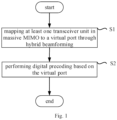
- Fig. 1 shows a flow diagram of a method for virtual port mapping of massive MIMO according to an embodiment of the present disclosure.
- the mapping device maps at least one transceiver unit in massive MIMO to a virtual port through hybrid beamforming; in step S2, the mapping device performs digital precoding based on the virtual port.
- the hybrid beamforming includes analog beamforming and digital precoding.
- the hybrid beamforming step includes: performing analog beamforming in a plurality of transceiver units in massive MIMO; performing digital precoding between the plurality of transceiver units after the analog beamforming to combine them into a virtual port.
- analog beamforming and digital precoding the plurality of transceiver units are mapped to a virtual port.
- the mapping device may use hybrid beamforming step to perform analog beamforming and digital precoding on the transceiver unit, so as to map the transceiver unit to a virtual port.
- the mapping device may only perform analog beamforming on the transceiver unit.
- step S2 the mapping device performs digital precoding based on the virtual port.
- its digital precoding is regarded as a unit matrix.
- each virtual port includes at least one transceiver unit to be mapped to antenna port as a minimum unit. Then, the traditional digital precoding is transferred from the transceiver units onto the virtual port.
- the plurality of transceiver units included therein may be mapped to different virtual ports in one or more ways.
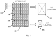
- Fig. 2 shows a schematic diagram of a virtual port mapping according to a preferred embodiment of the present disclosure.
- Massive MIMO 20 contains 192 antenna elements (AE) in total; the transceiver unit 201 includes 6 antenna elements, and since these 6 antenna elements belong to two poles, the transceiver unit 201 represents 2 transceiver units (TRX), that is, each transceiver unit contains 3 antenna elements on the same pole. It can be seen that the massive MIMO 20 includes 64 transceiver units (TRX) in total.
- the virtual port 205 includes 16 transceiver units, through virtual port mapping technique, the 16 transceiver units are mapped to 2 virtual ports (corresponding to two poles respectively), and each virtual port includes 8 transceiver units.
- the virtual port 206 includes 4 transceiver units, through virtual port mapping technique, the 4 transceiver units are mapped to 2 virtual ports (corresponding to two poles respectively), and each virtual port includes 2 transceiver units.
- the position of the transceiver unit(s) between antenna arrays can affect the performance of the virtual port.
- the transceiver 201 and the transceiver 202 are mapped to a first virtual port
- the transceiver 203 and the transceiver 204 are mapped to a second virtual port
- the transceiver 201 and the transceiver 203 are mapped to a third virtual port
- the transceiver 202 and the transceiver 204 are mapped to a fourth virtual port
- the present disclosure further includes step S3 (not shown), wherein in step S3, the mapping device determines hybrid beamforming weight corresponding to at least one transceiver unit in massive MIMO; then, in step S1, the mapping device maps the at least one transceiver unit to a virtual port through hybrid beamforming according to the hybrid beamforming weight.
- the hybrid beamforming weight includes analog beamforming weight in transceiver unit and/or digital precoding weight between transceiver units.
- the analog beamforming weight in transceiver unit includes two setting modes: one is that the weight corresponding to each transceiver unit is different; the other is that the weight corresponding to each transceiver unit is the same.
- the former has higher diversity gain and the latter has higher beam gain.
- An appropriate weight setting manner may be selected based on actual demand and processing performance.
- the digital precoding weight between transceiver units includes two setting modes: one is to set the digital precoding weight based on user measurement feedback and/or uplink channel measurement, for example, first configure a part of transceiver units to map to a virtual port in a 1:1 manner to send pilot signals for user measurement feedback and/or base station uplink channel measurement, when the user measurement feedback and/or the base station uplink channel measurement information are obtained, the digital precoding weight is set based on the above information, and digital precoding is performed on the transceiver unit; and the other is to set a fixed digital precoding weight.
- the mapping device can determine the hybrid beamforming weight based on a default scheme, or can determine the hybrid beamforming weight in real time based on the current actual demand and processing performance. Then, in step S1, the mapping device performs mapping on the at least one transceiver unit according to the hybrid beamforming weight.
- Fig. 3 shows a flow diagram of a method for virtual port mapping of massive MIMO according to another embodiment of the present disclosure.
- the mapping device determines one or more virtual port modes for massive MIMO according to user distribution of the cell served by the massive MIMO, where the virtual port modes comprise the number of virtual ports corresponding to the massive MIMO, the number of transceiver units in each virtual port, and position information of the transceiver units among antenna arrays; in step S1, the mapping device maps, based on the virtual port mode, at least one transceiver unit in the massive MIMO to a virtual port corresponding to the transceiver unit in the virtual port mode through hybrid beamforming; in step S2, the mapping device performs digital precoding based on the virtual port.
- step S2 is the same as or similar to the step S2 shown in Fig. 1 , so it is not repeated here and is included here by reference.
- step S4 the mapping device determines one or more virtual port modes for the massive MIMO in a real-time determined or predetermined manner.
- step S4 the mapping device obtains the user distribution of the cell served by the massive MIMO directly, or analyzes the current scenario to obtain the user distribution; wherein the user distribution includes the position of user in the cell, the distance between user and the massive MIMO, the angle between user and the massive MIMO, the signal strength of user, and the like.
- the mapping device determines one or more virtual port modes for the massive MIMO according to the determined user distribution, where the virtual port mode is a mapping mode for mapping at least one transceiver unit in the massive MIMO to different virtual ports in a grouped manner, and the virtual port mode includes the number of virtual ports corresponding to the massive MIMO, the number of transceiver units in each virtual port, and position information of the transceiver units among antenna arrays.
- the virtual port mode is a mapping mode for mapping at least one transceiver unit in the massive MIMO to different virtual ports in a grouped manner
- the virtual port mode includes the number of virtual ports corresponding to the massive MIMO, the number of transceiver units in each virtual port, and position information of the transceiver units among antenna arrays.
- step S4 the mapping device determines one or more candidate virtual port modes for the massive MIMO in advance according to the potential user distribution of the cell served by the massive MIMO, wherein the potential user distribution may be determined based on historical data of the serving cell or other serving cells, or may be determined based on system default settings.
- the mapping device determines at least one candidate virtual port mode as the virtual port modes corresponding to the massive MIMO by a preset or real-time selection mode according to the current time domain and/or frequency domain demand information of the cell served by the massive MIMO.
- the downlink virtual port number/virtual port size and downlink transmit power allocation can be automatically adjusted based on the following two factors:
- the present disclosure can judge the distance of the user based on the above two factors, and further determine the required downlink virtual port number/virtual port size and the downlink transmission power. For example, a greater number of virtual ports or a greater virtual port size may be allocated for cell edge users.
- the mapping device may determine a plurality of virtual port modes for use.
- step S 1 based on the virtual port modes, at least one transceiver unit in the massive MIMO is mapped to a virtual port corresponding to the transceiver unit in the virtual port modes through hybrid beamforming.
- Fig. 4 shows a schematic diagram of a virtual port mapping mode according to a preferred embodiment of the present disclosure.
- the massive MIMO 40 includes a total of 192 Antenna Elements (AE), and the 192 Antenna elements constitute 64 transceiver units.
- AE Antenna Elements
- 64 transceiver units are mapped to 24 virtual ports, wherein the virtual port 401 includes 8 transceiver units, the virtual port 402 and the virtual port 403 include 4 transceiver units.
- the virtual port 401 is used for user equipment 404 at the cell edge; while the virtual port 402 and the virtual port 403 are used for user equipment 405, user equipment 406, user equipment 407 and user equipment 408 inside the cell.
- Fig. 5 shows a schematic diagram of a mapping device for virtual port mapping of massive MIMO according to an embodiment of the present disclosure; wherein, the mapping device 50 includes a first means 501 and a second means 502.
- the first means 501 maps at least one transceiver unit in massive MIMO to a virtual port through hybrid beamforming; the second means 502 performs digital precoding based on the virtual port.
- the hybrid beamforming includes analog beamforming and digital precoding.
- the hybrid beamforming step includes: performing analog beamforming in a plurality of transceiver units in massive MIMO; performing digital precoding between the plurality of transceiver units after the analog beamforming to combine them into a virtual port.
- analog beamforming and digital precoding the plurality of transceiver units are mapped to a virtual port.
- the mapping device may use hybrid beamforming step to perform analog beamforming and digital precoding on the transceiver unit, so as to map the transceiver unit to a virtual port.
- the mapping device may only perform analog beamforming on the transceiver unit.
- the second means 502 performs digital precoding based on the virtual port.
- its digital precoding is regarded as a unit matrix.
- each virtual port includes at least one transceiver unit to be mapped to antenna port as a minimum unit. Then, the traditional digital precoding is transferred from the transceiver units onto the virtual port.
- the plurality of transceiver units included therein may be mapped to different virtual ports in one or more ways.
- the mapping device 50 further includes a third means (not shown), wherein, the third means determines hybrid beamforming weight corresponding to at least one transceiver unit in massive MIMO; then, the first means 501 maps the at least one transceiver unit to a virtual port through hybrid beamforming according to the hybrid beamforming weight.
- the third means determines hybrid beamforming weight corresponding to at least one transceiver unit in massive MIMO; then, the first means 501 maps the at least one transceiver unit to a virtual port through hybrid beamforming according to the hybrid beamforming weight.
- the hybrid beamforming weight includes analog beamforming weight in transceiver unit and/or digital precoding weight between transceiver units.
- the analog beamforming weight in transceiver unit includes two setting modes: one is that the weight corresponding to each transceiver unit is different; the other is that the weight corresponding to each transceiver unit is the same.
- the former has higher diversity gain and the latter has higher beam gain.
- An appropriate weight setting manner may be selected based on actual demand and processing performance.
- the digital preceding weight between transceiver units includes two setting modes: one is to set the digital precoding weight based on user measurement feedback and/or uplink channel measurement, for example, first configure a part of transceiver units to map to a virtual port in a 1:1 manner to send pilot signals for user measurement feedback and/or base station uplink channel measurement, when the user measurement feedback and/or the base station uplink channel measurement information are obtained, the digital precoding weight is set based on the above information, and digital precoding is performed on the transceiver unit; and the other is to set a fixed digital precoding weight.
- the third means can determine the hybrid beamforming weight based on a default scheme, or can determine the hybrid beamforming weight in real time based on the current actual demand and processing performance. Then, the first means 501 performs mapping on the at least one transceiver unit according to the hybrid beamforming weight.
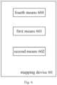
- Fig. 6 shows a schematic diagram of a mapping device for virtual port mapping of massive MIMO according to another embodiment of the present disclosure.
- the mapping device 50 includes a fourth means 604, a first means 601 and a second means 602.
- the fourth means 604 determines one or more virtual port modes for massive MIMO according to user distribution of the cell served by the massive MIMO, where the virtual port modes comprise the number of virtual ports corresponding to the massive MIMO, the number of transceiver units in each virtual port, and position information of the transceiver units among antenna arrays; the first means 601 maps, based on the virtual port mode, at least one transceiver unit in the massive MIMO to a virtual port corresponding to the transceiver unit in the virtual port mode through hybrid beamforming; the second means 602 performs digital precoding based on the virtual port.
- the second means 602 is the same as or similar to the second means 502 shown in Fig. 5 , so it is not repeated here and is included here by reference.
- the fourth means 604 determines one or more virtual port modes for the massive MIMO in a real-time determined or predetermined manner.
- the fourth means 604 obtains the user distribution of the cell served by the massive MIMO directly, or analyzes the current scenario to obtain the user distribution; wherein the user distribution includes the position of user in the cell, the distance between user and the massive MIMO, the angle between user and the massive MIMO, the signal strength of user, and the like.
- the mapping device determines one or more virtual port modes for the massive MIMO according to the determined user distribution, where the virtual port mode is a mapping mode for mapping at least one transceiver unit in the massive MIMO to different virtual ports in a grouped manner, and the virtual port mode includes the number of virtual ports corresponding to the massive MIMO, the number of transceiver units in each virtual port, and position information of the transceiver units among antenna arrays.
- the virtual port mode is a mapping mode for mapping at least one transceiver unit in the massive MIMO to different virtual ports in a grouped manner
- the virtual port mode includes the number of virtual ports corresponding to the massive MIMO, the number of transceiver units in each virtual port, and position information of the transceiver units among antenna arrays.
- the fourth means 604 determines one or more candidate virtual port modes for the massive MIMO in advance according to the potential user distribution of the cell served by the massive MIMO, wherein the potential user distribution may be determined based on historical data of the serving cell or other serving cells, or may be determined based on system default settings.
- the fourth means 604 determines at least one candidate virtual port mode as the virtual port modes corresponding to the massive MIMO by a preset or real-time selection mode according to the current time domain and/or frequency domain demand information of the cell served by the massive MIMO.
- the downlink virtual port number/virtual port size and downlink transmit power allocation can be automatically adjusted based on the following two factors:
- the present disclosure can judge the distance of the user based on the above two factors, and further determine the required downlink virtual port number/virtual port size and the downlink transmission power. For example, a greater number of virtual ports or a greater virtual port size may be allocated for cell edge users.
- the mapping device may determine a plurality of virtual port modes for use.
- the first means 601 based on the virtual port modes, at least one transceiver unit in the massive MIMO is mapped to a virtual port corresponding to the transceiver unit in the virtual port modes through hybrid beamforming.
- FIG. 7 shows an exemplary system that can be used to implement the various embodiments described in the present disclosure.
- system 70 can be implemented as any device in the embodiments shown in Fig. 1 , Fig. 2 , Fig. 3 , Fig. 4 , Fig. 5 , Fig. 6 , or other described embodiments.
- system 70 may include one or more computer readable media (e.g., system memory or NVM/storage device 720) having instructions and one or more processors (e.g., processor(s) 705) coupled with the one or more computer readable media and configured to execute the instructions to implement modules to perform the actions described in the present disclosure.
- processors e.g., processor(s) 705
- system control module 710 may include any suitable interface controller to provide any suitable interface to at least one of processor(s) 705 and/or to any suitable device or component in communication with system control module 710.
- the system control module 710 may include a memory controller module 730 to provide an interface to the system memory 715.
- Memory controller module 730 may be a hardware module, a software module, and/or a firmware module.
- System memory 715 may be used to load and store data and/or instructions, for example, for system 70.
- system memory 715 may include any suitable volatile memory, such as suitable DRAM.
- system memory 715 may include a Double Data Rate type Fourth Synchronous Dynamic Random Access Memory (DDR4 SDRAM).
- DDR4 SDRAM Double Data Rate type Fourth Synchronous Dynamic Random Access Memory
- system control module 710 may include one or more input/output (I/O) controllers to provide an interface to NVM/storage device 720 and communication interface(s) 725.
- I/O input/output
- NVM/storage device 720 may be used to store data and/or instructions.
- NVM/storage device 720 may include any suitable non-volatile memory (e.g., flash memory) and/or may include any suitable non-volatile storage device(s) (e.g., one or more hard disk drives (HDD), one or more Compact Disc (CD) drives, and/or one or more Digital Versatile Disc (DVD) drives).
- HDD hard disk drives
- CD Compact Disc
- DVD Digital Versatile Disc
- NVM/storage device 720 may include storage resources that are physically part of the device on which system 70 is installed, or it may be accessible by the device and not necessarily to be part of the device. For example, NVM/storage device 720 may be accessed via the communication interface(s) 725 through the network.
- Communication interface(s) 725 may provide an interface for system 70 to communicate via one or more networks and/or with any other suitable devices.
- System 70 may wirelessly communicate with one or more components of a wireless network according to any of one or more wireless network standards and/or protocols.
- At least one of the processor(s) 705 may be packaged together with logic for one or more controller(s) (e.g., memory controller module 730) of the system control module 710.
- at least one of the processor(s) 705 may be packaged together with logic for one or more controller(s) of the system control module 710 to form a System in Package (SiP).
- SiP System in Package
- at least one of the processor(s) 705 may be integrated with logic for one or more controller(s) of the system control module 710 on the same mold.
- at least one of the processor(s) 705 may be integrated with logic for one or more controller(s) of system control module 710 on the same mold to form a system on chip (SoC).
- SoC system on chip
- the system 70 may be, but is not limited to being: a server, a workstation, a desktop computing device, or a mobile computing device (for example, a laptop computing device, a handheld computing device, a tablet, a netbook, etc.).
- the system 70 may have more or fewer components and/or different architectures.
- the system 70 includes one or more cameras, a keyboard, a Liquid Crystal Display (LCD) screen (including a touch screen display), a non-volatile memory port, multiple antennas, a graphics chip, an Application Specific Integrated Circuit (ASIC), and speakers.
- LCD Liquid Crystal Display
- ASIC Application Specific Integrated Circuit
- the present application may be implemented in software and/or a combination of software and hardware, for example, it can be implemented using an Application Specific Integrated Circuit (ASIC), a general purpose computer or any other similar hardware device.
- ASIC Application Specific Integrated Circuit
- the software programs of the present application may be executed by a processor to implement the steps or functions described above.
- the software programs (including associated data structures) of the present application can be stored in a computer readable recording medium, such as RAM memory, magnetic or optical drive or diskette and the like.
- some steps or functions of the present application may be implemented by hardware, for example, as a circuit that cooperates with the processor to perform each step or function.
- a part of the present application may be applied as a computer program product, such as computer program instructions, which, when executed by a computer, may invoke or provide the method and/or solution according to the present application through the operation of the computer.
- computer program instructions that reside on a computer readable medium include, but are not limited to, source files, executable files, installation package files, and the like, and that the manner in which the computer program instructions are executed by a computer includes, but is not limited to: the computer directly executes the instruction, or the computer compiles the instruction and then executes the corresponding compiled program, or the computer reads and executes the instruction, or the computer reads and installs the instruction and then executes the corresponding installed program.
- computer readable media can be any available computer readable storage media or communication media that can be accessed by a computer.
- Communication media includes media whereby communication signals, including, for example, computer readable instructions, data structures, program modules, or other data, are transmitted from one system to another.
- Communication media may include conductive transmission media (such as cables and wires (e.g., fiber optics, coaxial, etc.)) and wireless (non-conductive transmission) media capable of propagating energy waves, such as sound, electromagnetic, RF, microwave, and infrared.
- Computer readable instructions, data structures, program modules or other data may be embodied as, for example, a modulated data signal in a wireless medium (such as a carrier wave or such as a similar mechanism embodied as part of spread spectrum technology).
- modulated data signal means a signal that has one or more of its characteristics set or changed in such a manner as to encode information in the signal. The modulation may be analog, digital, or hybrid modulation techniques.
- computer-readable storage media may include volatile and nonvolatile, removable and non-removable media implemented in any method or technology for storage of information such as computer-readable instructions, data structures, program modules or other data.
- computer-readable storage media include, but are not limited to, volatile memory such as random access memory (RAM, DRAM, SRAM); and non-volatile memory such as flash memory, various read-only memories (ROM, PROM, EPROM, EEPROM), magnetic and ferromagnetic/ferroelectric memories (MRAM, FeRAM); and magnetic and optical storage devices (hard disk, magnetic tape, CD, DVD); or other now known media or later developed that are capable of storing computer-readable information/data for use by a computer system.
- volatile memory such as random access memory (RAM, DRAM, SRAM)
- non-volatile memory such as flash memory, various read-only memories (ROM, PROM, EPROM, EEPROM), magnetic and ferromagnetic/ferroelectric memories (MRAM, FeRAM); and magnetic and optical storage devices (hard disk, magnetic
- An embodiment according to the present application herein comprises an apparatus comprising a memory for storing computer program instructions and a processor for executing the program instructions, wherein the computer program instructions, when executed by the processor, trigger the apparatus to perform a method and/or solution according to embodiments of the present application as described above.
Landscapes
- Engineering & Computer Science (AREA)
- Computer Networks & Wireless Communication (AREA)
- Signal Processing (AREA)
- Mobile Radio Communication Systems (AREA)
- Radio Transmission System (AREA)
Claims (13)
- Verfahren für eine virtuelle Portzuordnung einer Massive-MIMO-Einheit (20), wobei das Verfahren Folgendes umfasst:Zuordnen (S1) von mindestens einer Sendeempfängereinheit in der Massive-MIMO-Einheit (20) über eine hybride Strahlformung zu einem virtuellen Port;Durchführen (S2) einer digitalen Vorcodierung auf Basis des virtuellen Ports, wobei das Verfahren ferner Folgendes umfasst:Bestimmen (S4) von einem oder mehreren virtuellen Portmodi für die Massive-MIMO-Einheit (20) gemäß einer Benutzerverteilung der Zelle, die von der Massive-MIMO-Einheit (20) bedient wird, wobei die virtuellen Portmodi die Anzahl von virtuellen Ports, die der Massive-MIMO-Einheit (20) entsprechen, die Anzahl von Sendeempfängereinheiten in jedem virtuellen Port und Positionsinformationen der Sendeempfängereinheiten unter Antennenarrays umfassen;wobei der Schritt des Zuordnens (S1) zu einem virtuellen Port Folgendes umfasst:
Zuordnen von mindestens einer Sendeempfängereinheit in der Massive-MIMO-Einheit (20) auf Basis des virtuellen Portmodus zu einem virtuellen Port, der der Sendeempfängereinheit im virtuellen Portmodus entspricht, über eine hybride Strahlformung. - Verfahren nach Anspruch 1, wobei der Schritt der hybriden Strahlformung Folgendes umfasst:Durchführen einer analogen Strahlformung in mindestens einer Sendeempfängereinheit in der Massive-MIMO-Einheit (20);Durchführen einer digitalen Vorcodierung zwischen den Sendeempfängereinheiten nach der analogen Strahlformung.
- Verfahren nach Anspruch 1 oder 2, wobei das Verfahren ferner Folgendes umfasst:Durchführen einer hybriden Strahlformungsgewichtung, die mindestens einer Sendeempfängereinheit in der Massive-MIMO-Einheit (20) entspricht;wobei der Schritt des Zuordnens zu einem virtuellen Port Folgendes umfasst:
Zuordnen der mindestens einen Sendeempfängereinheit über eine hybride Strahlformung gemäß der hybriden Strahlformungsgewichtung zu einem virtuellen Port. - Verfahren nach Anspruch 3, wobei die hybride Strahlformungsgewichtung eine analoge Strahlformungsgewichtung in einer Sendeempfängereinheit und/oder eine digitale Vorcodierungsgewichtung zwischen Sendeempfängereinheiten umfasst.
- Verfahren nach Anspruch 1, wobei der Schritt des Bestimmens (S4) von einem oder mehreren virtuellen Portmodi für die Massive-MIMO-Einheit (20) Folgendes umfasst:Bestimmen von einem oder mehreren virtuellen Portmoduskandidaten für die Massive-MIMO-Einheit (20) gemäß der potenziellen Benutzerverteilung der Zelle, die von der Massive-MIMO-Einheit (20) bedient wird, wobei die virtuellen Portmoduskandidaten die Anzahl von virtuellen Ports, die der Massive-MIMO-Einheit (20) entsprechen, die Anzahl von Sendeempfängereinheiten in jedem virtuellen Port und Positionsinformationen der Sendeempfängereinheiten unter Antennenarrays umfassen;Bestimmen von mindestens einem virtuellen Portmoduskandidaten als die virtuellen Portmodi, die der Massive-MIMO-Einheit (20) entsprechen, gemäß den Informationen zu einem aktuellen Zeitdomänen- und/oder Frequenzdomänenbedarf der Zelle, die von der Massive-MIMO-Einheit (20) bedient wird.
- Zuordnungsvorrichtung (50) für eine virtuelle Portzuordnung einer Massive-MIMO-Einheit (20), wobei die Zuordnungsvorrichtung (50) Folgendes umfasst:Mittel (501) zum Zuordnen (S1) von mindestens einer Sendeempfängereinheit in der Massive-MIMO-Einheit (20) über eine hybride Strahlformung zu einem virtuellen Port;Mittel (502) zum Durchführen einer digitalen Vorcodierung (S2) auf Basis des virtuellen Ports, wobei die Zuordnungsvorrichtung ferner Folgendes umfasst:Mittel zum Bestimmen von einem oder mehreren virtuellen Portmodi für die Massive-MIMO-Einheit (20) gemäß einer Benutzerverteilung der Zelle, die von der Massive-MIMO-Einheit (20) bedient wird, wobei die virtuellen Portmodi die Anzahl von virtuellen Ports, die der Massive-MIMO-Einheit (20) entsprechen, die Anzahl von Sendeempfängereinheiten in jedem virtuellen Port und Positionsinformationen der Sendeempfängereinheiten unter Antennenarrays umfassen;wobei die Mittel zum Zuordnen von mindestens einer Sendeempfängereinheit in der Massive-MIMO-Einheit (20) über eine hybride Strahlformung zu einem virtuellen Port zu Folgendem ausgelegt sind:
Zuordnen von mindestens einer Sendeempfängereinheit in der Massive-MIMO-Einheit (20) auf Basis des virtuellen Portmodus zu einem virtuellen Port, der der Sendeempfängereinheit im virtuellen Portmodus entspricht, über eine hybride Strahlformung. - Zuordnungsvorrichtung (50) nach Anspruch 6, wobei die Mittel zum Zuordnen von mindestens einer Sendeempfängereinheit in der Massive-MIMO-Einheit (20) über eine hybride Strahlformung zu einem virtuellen Port zu Folgendem ausgelegt sind:Durchführen einer analogen Strahlformung in mindestens einer Sendeempfängereinheit in der Massive-MIMO-Einheit (20);Durchführen einer digitalen Vorcodierung zwischen den Sendeempfängereinheiten nach der analogen Strahlformung.
- Zuordnungsvorrichtung (50) nach Anspruch 6 oder 7, wobei die Zuordnungsvorrichtung ferner Folgendes umfasst:Mittel zum Durchführen einer hybriden Strahlformungsgewichtung, die mindestens einer Sendeempfängereinheit in der Massive-MIMO-Einheit (20) entspricht;wobei die Mittel zum Zuordnen von mindestens einer Sendeempfängereinheit in der Massive-MIMO-Einheit (20) über eine hybride Strahlformung zu einem virtuellen Port zu Folgendem ausgelegt sind:
Zuordnen der mindestens einen Sendeempfängereinheit über eine hybride Strahlformung gemäß der hybriden Strahlformungsgewichtung zu einem virtuellen Port. - Zuordnungsvorrichtung (50) nach Anspruch 8, wobei die hybride Strahlformungsgewichtung eine analoge Strahlformungsgewichtung in einer Sendeempfängereinheit und/oder eine digitale Vorcodierungsgewichtung zwischen Sendeempfängereinheiten umfasst.
- Zuordnungsvorrichtung (50) nach Anspruch 6, wobei die Mittel zum Bestimmen von einem oder mehreren virtuellen Portmodi für die Massive-MIMO-Einheit (20) zu Folgendem ausgelegt sind:Bestimmen von einem oder mehreren virtuellen Portmoduskandidaten für die Massive-MIMO-Einheit (20) gemäß der potenziellen Benutzerverteilung der Zelle, die von der Massive-MIMO-Einheit (20) bedient wird, wobei die virtuellen Portmoduskandidaten die Anzahl von virtuellen Ports, die der Massive-MIMO-Einheit (20) entsprechen, die Anzahl von Sendeempfängereinheiten in jedem virtuellen Port und Positionsinformationen der Sendeempfängereinheiten unter Antennenarrays umfassen;Bestimmen von mindestens einem virtuellen Portmoduskandidaten als die virtuellen Portmodi, die der Massive-MIMO-Einheit (20) entsprechen, gemäß den Informationen zu einem aktuellen Zeitdomänen- und/oder Frequenzdomänenbedarf der Zelle, die von der Massive-MIMO-Einheit (20) bedient wird.
- Basisstation für eine virtuelle Zuordnung einer Massive-MIMO-Einheit (20), wobei die Basisstation die Zuordnungsvorrichtung nach einem der Ansprüche 6 bis 10 umfasst.
- Computerlesbares Speichermedium (720), auf dem computerlesbare Anweisungen gespeichert sind, die, wenn sie von einem oder mehreren Prozessoren ausgeführt werden, die Zuordnungsvorrichtung nach Anspruch 6 veranlassen, das Verfahren nach einem der Ansprüche 1 bis 5 durchzuführen.
- Computervorrichtung, wobei die Computervorrichtung Folgendes umfasst:einen oder mehrere Prozessoren (705);einen Speicher zum Speichern von einem oder mehreren Computerprogrammen;wobei das eine oder die mehreren Computerprogramme, wenn sie von dem einen oder den mehreren Prozessoren (705) ausgeführt werden, die Zuordnungsvorrichtung nach Anspruch 6 veranlassen, das Verfahren nach einem der Ansprüche 1 bis 5 zu implementieren.
Applications Claiming Priority (1)
| Application Number | Priority Date | Filing Date | Title |
|---|---|---|---|
| PCT/CN2018/083604 WO2019200570A1 (zh) | 2018-04-18 | 2018-04-18 | 一种用于大规模mimo的虚拟端口映射的方法与装置 |
Publications (3)
| Publication Number | Publication Date |
|---|---|
| EP3783806A1 EP3783806A1 (de) | 2021-02-24 |
| EP3783806A4 EP3783806A4 (de) | 2022-03-23 |
| EP3783806B1 true EP3783806B1 (de) | 2024-08-21 |
Family
ID=68240597
Family Applications (1)
| Application Number | Title | Priority Date | Filing Date |
|---|---|---|---|
| EP18915011.3A Active EP3783806B1 (de) | 2018-04-18 | 2018-04-18 | Verfahren und vorrichtung zur abbildung virtueller ports für massive-mimo |
Country Status (4)
| Country | Link |
|---|---|
| US (1) | US11528062B2 (de) |
| EP (1) | EP3783806B1 (de) |
| CN (1) | CN111903071B (de) |
| WO (1) | WO2019200570A1 (de) |
Families Citing this family (4)
| Publication number | Priority date | Publication date | Assignee | Title |
|---|---|---|---|---|
| US12200640B2 (en) * | 2019-11-19 | 2025-01-14 | Qualcomm Incorporated | Signaling and configuration of maximum transmit power using virtual ports |
| CN113972936B (zh) | 2020-07-23 | 2023-01-06 | 华为技术有限公司 | 下行发射系统和切换方法 |
| CN115720102B (zh) * | 2021-08-24 | 2024-11-22 | 上海华为技术有限公司 | 一种无线通信方法、相关装置及设备 |
| CN121620877A (zh) * | 2023-07-21 | 2026-03-06 | 诺基亚通信(上海)股份有限公司 | 用于大规模多输入多输出的设备、方法、装置和计算机可读介质 |
Family Cites Families (22)
| Publication number | Priority date | Publication date | Assignee | Title |
|---|---|---|---|---|
| CN103023545B (zh) * | 2011-09-23 | 2018-04-06 | 中兴通讯股份有限公司 | 一种无线数据传输方法及网络侧设备 |
| EP2777172B1 (de) | 2011-11-11 | 2017-03-15 | Telefonaktiebolaget LM Ericsson (publ) | Verfahren, vorrichtung und system zur dynamischen konfiguration von gruppenantennen |
| CN102611489B (zh) * | 2012-03-19 | 2015-05-27 | 华为技术有限公司 | 四端口双极化天线传输数据的方法和基站 |
| CN103391128B (zh) | 2012-05-07 | 2017-08-18 | 华为技术有限公司 | 一种虚拟天线映射方法及装置 |
| KR102079629B1 (ko) * | 2013-05-02 | 2020-02-21 | 삼성전자주식회사 | 무선 통신 시스템에서 하이브리드 빔포밍의 복잡도 개선을 위한 방법 및 장치 |
| JP6673824B2 (ja) * | 2013-11-04 | 2020-04-01 | エルジー エレクトロニクス インコーポレイティド | 無線通信システムにおいて信号を送信する方法及び装置 |
| KR102213362B1 (ko) | 2014-03-03 | 2021-02-08 | 삼성전자 주식회사 | Mimo 시스템에서 가상 안테나 매핑 정보를 피드백하는 가상 안테나 매핑 방법 및 장치 |
| KR102231078B1 (ko) * | 2014-06-03 | 2021-03-24 | 삼성전자 주식회사 | 이동 통신 시스템에서 피드백 송수신 방법 및 장치 |
| CN106716862A (zh) * | 2014-10-29 | 2017-05-24 | 富士通株式会社 | 码书确定方法、装置以及通信系统 |
| US9806778B2 (en) * | 2014-11-11 | 2017-10-31 | Electronics And Telecommunications Research Institute | Method and apparatus for mapping virtual antenna to physical antenna |
| CN105991172A (zh) * | 2015-02-16 | 2016-10-05 | 富士通株式会社 | 天线阵列的虚拟化模型选择方法、装置以及通信系统 |
| KR20170128452A (ko) * | 2015-03-31 | 2017-11-22 | 후지쯔 가부시끼가이샤 | 빔 정보를 취득하는 방법, 장치 및 통신 시스템 |
| US9787387B2 (en) * | 2015-05-15 | 2017-10-10 | Electronics And Telecommunications Research Institute | Method and apparatus for virtualizing antenna in multi-antenna system, and method and apparatus for transmitting and receiving signal using the same |
| EP3327943B1 (de) * | 2015-07-23 | 2024-01-03 | LG Electronics Inc. | Codebuch-basiertes signalübertragungs- und -empfangsverfahren in einem mehrantennen-drahtloskommunikationssystem und vorrichtung dafür |
| CN108476499B (zh) * | 2016-01-19 | 2022-09-23 | 诺基亚通信公司 | 无线网络中相同链路方向的子帧部分之间的保护时段 |
| EP3446416B1 (de) * | 2016-05-13 | 2020-11-04 | Huawei Technologies Co., Ltd. | Vorcodierung und kanalstatusinformationserfassung für mehrdatenstromübertragungen in massiven mimo-systemen |
| EP3488537A1 (de) * | 2016-07-21 | 2019-05-29 | Interdigital Patent Holdings, Inc. | Setup mit mehreren eingängen und mehreren ausgängen (mimo) in wlan-systemen mit millimeterwellen (mmw) |
| EP3497818A1 (de) * | 2016-08-10 | 2019-06-19 | IDAC Holdings, Inc. | Räumliche modulation für drahtlose systeme der nächsten generation |
| CN106716856B (zh) | 2016-12-15 | 2021-02-09 | 香港应用科技研究院有限公司 | 闭环大规模mimo系统架构 |
| US10044420B2 (en) * | 2016-12-15 | 2018-08-07 | Hong Kong Applied Science and Technology Research Institute Company Limited | Closed-loop massive MIMO system architecture |
| CN108366422B (zh) * | 2017-01-26 | 2021-02-26 | 华为技术有限公司 | 小区间波束协调调度方法和相关设备 |
| US11218210B2 (en) * | 2017-05-30 | 2022-01-04 | Telefonaktiebolaget Lm Ericsson (Publ) | Technique for channel state acquisition |
-
2018
- 2018-04-18 EP EP18915011.3A patent/EP3783806B1/de active Active
- 2018-04-18 CN CN201880091804.3A patent/CN111903071B/zh active Active
- 2018-04-18 WO PCT/CN2018/083604 patent/WO2019200570A1/zh not_active Ceased
- 2018-04-18 US US17/047,501 patent/US11528062B2/en active Active
Also Published As
| Publication number | Publication date |
|---|---|
| EP3783806A4 (de) | 2022-03-23 |
| EP3783806A1 (de) | 2021-02-24 |
| WO2019200570A1 (zh) | 2019-10-24 |
| US11528062B2 (en) | 2022-12-13 |
| CN111903071A (zh) | 2020-11-06 |
| CN111903071B (zh) | 2023-02-03 |
| US20210152221A1 (en) | 2021-05-20 |
Similar Documents
| Publication | Publication Date | Title |
|---|---|---|
| CN115133959B (zh) | 用于多面板ue的波束指示 | |
| CN110476365B (zh) | 用于新无线上行链路单用户多输入多输出通信的功率控制 | |
| EP3557808A1 (de) | Leistungssteuerungsverfahren für uplink-referenzmesssignal, netzwerkvorrichtung und endgerätevorrichtung | |
| EP3783806B1 (de) | Verfahren und vorrichtung zur abbildung virtueller ports für massive-mimo | |
| AU2019443559B2 (en) | Transmission of reference signals from a terminal device | |
| EP3954058A1 (de) | Verfahren und vorrichtungen zur strahlformungsoptimierung | |
| US12562789B2 (en) | System and methods for configurable EIRP restriction | |
| US20240146358A1 (en) | Method and device for reporting channel state information in wireless communication system supporting reconfigurable intelligent surface | |
| KR20210126095A (ko) | 단말 장치로부터의 기준 신호의 전송 | |
| US12542582B2 (en) | Reconfigurable intelligent surface | |
| EP3387753B1 (de) | Vorrichtung und verfahren zur steuerung von verstärkern | |
| KR20190042828A (ko) | 무선 통신 시스템에서 송신 전력을 제어하기 위한 장치 및 방법 | |
| CN112825490B (zh) | 一种虚拟天线映射方法及网络设备 | |
| US20260052468A1 (en) | Methods and systems for saving network energy in spatial domain using adaptation information | |
| JP7450533B2 (ja) | 基地局装置、通信方法及び無線通信システム | |
| WO2023109947A1 (zh) | 上下行非对称通信mimo系统的劈裂波束管理方法及系统 | |
| US11153003B2 (en) | Cell-specific signal generation | |
| JP2026506679A (ja) | 空間領域および電力領域における省エネルギー | |
| EP3915201B1 (de) | Verfahren und vorrichtungen zur kommunikation mittels strahlformung | |
| RU2811989C1 (ru) | Устройство и способ формирования диаграммы направленности для нисходящей передачи данных в системе беспроводной связи | |
| US20260101319A1 (en) | Pusch transmission method and apparatus, medium, and product | |
| WO2024250248A1 (zh) | 一种通信方法及装置 | |
| EP3963739A1 (de) | Übertragung von referenzsignalen von einer endgerätevorrichtung | |
| KR101974262B1 (ko) | 단일 rf 체인을 사용하는 통신 방법 및 단일 rf 체인을 사용하는 통신 장치 | |
| CN121773569A (zh) | 一种通信方法及装置 |
Legal Events
| Date | Code | Title | Description |
|---|---|---|---|
| STAA | Information on the status of an ep patent application or granted ep patent |
Free format text: STATUS: THE INTERNATIONAL PUBLICATION HAS BEEN MADE |
|
| PUAI | Public reference made under article 153(3) epc to a published international application that has entered the european phase |
Free format text: ORIGINAL CODE: 0009012 |
|
| STAA | Information on the status of an ep patent application or granted ep patent |
Free format text: STATUS: REQUEST FOR EXAMINATION WAS MADE |
|
| 17P | Request for examination filed |
Effective date: 20201105 |
|
| AK | Designated contracting states |
Kind code of ref document: A1 Designated state(s): AL AT BE BG CH CY CZ DE DK EE ES FI FR GB GR HR HU IE IS IT LI LT LU LV MC MK MT NL NO PL PT RO RS SE SI SK SM TR |
|
| AX | Request for extension of the european patent |
Extension state: BA ME |
|
| DAV | Request for validation of the european patent (deleted) | ||
| DAX | Request for extension of the european patent (deleted) | ||
| RIC1 | Information provided on ipc code assigned before grant |
Ipc: H04B 7/06 20060101AFI20211108BHEP |
|
| REG | Reference to a national code |
Free format text: PREVIOUS MAIN CLASS: H04B0007040000 Ipc: H04B0007060000 Ref country code: DE Ref legal event code: R079 Ref document number: 602018073499 Country of ref document: DE Free format text: PREVIOUS MAIN CLASS: H04B0007040000 Ipc: H04B0007060000 |
|
| A4 | Supplementary search report drawn up and despatched |
Effective date: 20220217 |
|
| RIC1 | Information provided on ipc code assigned before grant |
Ipc: H04B 7/06 20060101AFI20220211BHEP |
|
| GRAP | Despatch of communication of intention to grant a patent |
Free format text: ORIGINAL CODE: EPIDOSNIGR1 |
|
| STAA | Information on the status of an ep patent application or granted ep patent |
Free format text: STATUS: GRANT OF PATENT IS INTENDED |
|
| INTG | Intention to grant announced |
Effective date: 20240403 |
|
| GRAS | Grant fee paid |
Free format text: ORIGINAL CODE: EPIDOSNIGR3 |
|
| GRAA | (expected) grant |
Free format text: ORIGINAL CODE: 0009210 |
|
| STAA | Information on the status of an ep patent application or granted ep patent |
Free format text: STATUS: THE PATENT HAS BEEN GRANTED |
|
| AK | Designated contracting states |
Kind code of ref document: B1 Designated state(s): AL AT BE BG CH CY CZ DE DK EE ES FI FR GB GR HR HU IE IS IT LI LT LU LV MC MK MT NL NO PL PT RO RS SE SI SK SM TR |
|
| REG | Reference to a national code |
Ref country code: GB Ref legal event code: FG4D |
|
| REG | Reference to a national code |
Ref country code: CH Ref legal event code: EP |
|
| REG | Reference to a national code |
Ref country code: DE Ref legal event code: R096 Ref document number: 602018073499 Country of ref document: DE |
|
| REG | Reference to a national code |
Ref country code: IE Ref legal event code: FG4D |
|
| REG | Reference to a national code |
Ref country code: LT Ref legal event code: MG9D |
|
| REG | Reference to a national code |
Ref country code: NL Ref legal event code: MP Effective date: 20240821 |
|
| PG25 | Lapsed in a contracting state [announced via postgrant information from national office to epo] |
Ref country code: NO Free format text: LAPSE BECAUSE OF FAILURE TO SUBMIT A TRANSLATION OF THE DESCRIPTION OR TO PAY THE FEE WITHIN THE PRESCRIBED TIME-LIMIT Effective date: 20241121 |
|
| REG | Reference to a national code |
Ref country code: AT Ref legal event code: MK05 Ref document number: 1716538 Country of ref document: AT Kind code of ref document: T Effective date: 20240821 |
|
| PG25 | Lapsed in a contracting state [announced via postgrant information from national office to epo] |
Ref country code: NL Free format text: LAPSE BECAUSE OF FAILURE TO SUBMIT A TRANSLATION OF THE DESCRIPTION OR TO PAY THE FEE WITHIN THE PRESCRIBED TIME-LIMIT Effective date: 20240821 Ref country code: FI Free format text: LAPSE BECAUSE OF FAILURE TO SUBMIT A TRANSLATION OF THE DESCRIPTION OR TO PAY THE FEE WITHIN THE PRESCRIBED TIME-LIMIT Effective date: 20240821 Ref country code: GR Free format text: LAPSE BECAUSE OF FAILURE TO SUBMIT A TRANSLATION OF THE DESCRIPTION OR TO PAY THE FEE WITHIN THE PRESCRIBED TIME-LIMIT Effective date: 20241122 Ref country code: PL Free format text: LAPSE BECAUSE OF FAILURE TO SUBMIT A TRANSLATION OF THE DESCRIPTION OR TO PAY THE FEE WITHIN THE PRESCRIBED TIME-LIMIT Effective date: 20240821 Ref country code: PT Free format text: LAPSE BECAUSE OF FAILURE TO SUBMIT A TRANSLATION OF THE DESCRIPTION OR TO PAY THE FEE WITHIN THE PRESCRIBED TIME-LIMIT Effective date: 20241223 |
|
| PG25 | Lapsed in a contracting state [announced via postgrant information from national office to epo] |
Ref country code: BG Free format text: LAPSE BECAUSE OF FAILURE TO SUBMIT A TRANSLATION OF THE DESCRIPTION OR TO PAY THE FEE WITHIN THE PRESCRIBED TIME-LIMIT Effective date: 20240821 |
|
| PG25 | Lapsed in a contracting state [announced via postgrant information from national office to epo] |
Ref country code: LV Free format text: LAPSE BECAUSE OF FAILURE TO SUBMIT A TRANSLATION OF THE DESCRIPTION OR TO PAY THE FEE WITHIN THE PRESCRIBED TIME-LIMIT Effective date: 20240821 |
|
| PG25 | Lapsed in a contracting state [announced via postgrant information from national office to epo] |
Ref country code: IS Free format text: LAPSE BECAUSE OF FAILURE TO SUBMIT A TRANSLATION OF THE DESCRIPTION OR TO PAY THE FEE WITHIN THE PRESCRIBED TIME-LIMIT Effective date: 20241221 Ref country code: AT Free format text: LAPSE BECAUSE OF FAILURE TO SUBMIT A TRANSLATION OF THE DESCRIPTION OR TO PAY THE FEE WITHIN THE PRESCRIBED TIME-LIMIT Effective date: 20240821 |
|
| PG25 | Lapsed in a contracting state [announced via postgrant information from national office to epo] |
Ref country code: HR Free format text: LAPSE BECAUSE OF FAILURE TO SUBMIT A TRANSLATION OF THE DESCRIPTION OR TO PAY THE FEE WITHIN THE PRESCRIBED TIME-LIMIT Effective date: 20240821 |
|
| PG25 | Lapsed in a contracting state [announced via postgrant information from national office to epo] |
Ref country code: RS Free format text: LAPSE BECAUSE OF FAILURE TO SUBMIT A TRANSLATION OF THE DESCRIPTION OR TO PAY THE FEE WITHIN THE PRESCRIBED TIME-LIMIT Effective date: 20241121 Ref country code: ES Free format text: LAPSE BECAUSE OF FAILURE TO SUBMIT A TRANSLATION OF THE DESCRIPTION OR TO PAY THE FEE WITHIN THE PRESCRIBED TIME-LIMIT Effective date: 20240821 |
|
| PG25 | Lapsed in a contracting state [announced via postgrant information from national office to epo] |
Ref country code: RS Free format text: LAPSE BECAUSE OF FAILURE TO SUBMIT A TRANSLATION OF THE DESCRIPTION OR TO PAY THE FEE WITHIN THE PRESCRIBED TIME-LIMIT Effective date: 20241121 Ref country code: PT Free format text: LAPSE BECAUSE OF FAILURE TO SUBMIT A TRANSLATION OF THE DESCRIPTION OR TO PAY THE FEE WITHIN THE PRESCRIBED TIME-LIMIT Effective date: 20241223 Ref country code: PL Free format text: LAPSE BECAUSE OF FAILURE TO SUBMIT A TRANSLATION OF THE DESCRIPTION OR TO PAY THE FEE WITHIN THE PRESCRIBED TIME-LIMIT Effective date: 20240821 Ref country code: NO Free format text: LAPSE BECAUSE OF FAILURE TO SUBMIT A TRANSLATION OF THE DESCRIPTION OR TO PAY THE FEE WITHIN THE PRESCRIBED TIME-LIMIT Effective date: 20241121 Ref country code: NL Free format text: LAPSE BECAUSE OF FAILURE TO SUBMIT A TRANSLATION OF THE DESCRIPTION OR TO PAY THE FEE WITHIN THE PRESCRIBED TIME-LIMIT Effective date: 20240821 Ref country code: LV Free format text: LAPSE BECAUSE OF FAILURE TO SUBMIT A TRANSLATION OF THE DESCRIPTION OR TO PAY THE FEE WITHIN THE PRESCRIBED TIME-LIMIT Effective date: 20240821 Ref country code: IS Free format text: LAPSE BECAUSE OF FAILURE TO SUBMIT A TRANSLATION OF THE DESCRIPTION OR TO PAY THE FEE WITHIN THE PRESCRIBED TIME-LIMIT Effective date: 20241221 Ref country code: HR Free format text: LAPSE BECAUSE OF FAILURE TO SUBMIT A TRANSLATION OF THE DESCRIPTION OR TO PAY THE FEE WITHIN THE PRESCRIBED TIME-LIMIT Effective date: 20240821 Ref country code: GR Free format text: LAPSE BECAUSE OF FAILURE TO SUBMIT A TRANSLATION OF THE DESCRIPTION OR TO PAY THE FEE WITHIN THE PRESCRIBED TIME-LIMIT Effective date: 20241122 Ref country code: FI Free format text: LAPSE BECAUSE OF FAILURE TO SUBMIT A TRANSLATION OF THE DESCRIPTION OR TO PAY THE FEE WITHIN THE PRESCRIBED TIME-LIMIT Effective date: 20240821 Ref country code: ES Free format text: LAPSE BECAUSE OF FAILURE TO SUBMIT A TRANSLATION OF THE DESCRIPTION OR TO PAY THE FEE WITHIN THE PRESCRIBED TIME-LIMIT Effective date: 20240821 Ref country code: BG Free format text: LAPSE BECAUSE OF FAILURE TO SUBMIT A TRANSLATION OF THE DESCRIPTION OR TO PAY THE FEE WITHIN THE PRESCRIBED TIME-LIMIT Effective date: 20240821 Ref country code: AT Free format text: LAPSE BECAUSE OF FAILURE TO SUBMIT A TRANSLATION OF THE DESCRIPTION OR TO PAY THE FEE WITHIN THE PRESCRIBED TIME-LIMIT Effective date: 20240821 |
|
| PG25 | Lapsed in a contracting state [announced via postgrant information from national office to epo] |
Ref country code: DK Free format text: LAPSE BECAUSE OF FAILURE TO SUBMIT A TRANSLATION OF THE DESCRIPTION OR TO PAY THE FEE WITHIN THE PRESCRIBED TIME-LIMIT Effective date: 20240821 Ref country code: SM Free format text: LAPSE BECAUSE OF FAILURE TO SUBMIT A TRANSLATION OF THE DESCRIPTION OR TO PAY THE FEE WITHIN THE PRESCRIBED TIME-LIMIT Effective date: 20240821 Ref country code: RO Free format text: LAPSE BECAUSE OF FAILURE TO SUBMIT A TRANSLATION OF THE DESCRIPTION OR TO PAY THE FEE WITHIN THE PRESCRIBED TIME-LIMIT Effective date: 20240821 |
|
| PG25 | Lapsed in a contracting state [announced via postgrant information from national office to epo] |
Ref country code: EE Free format text: LAPSE BECAUSE OF FAILURE TO SUBMIT A TRANSLATION OF THE DESCRIPTION OR TO PAY THE FEE WITHIN THE PRESCRIBED TIME-LIMIT Effective date: 20240821 |
|
| PG25 | Lapsed in a contracting state [announced via postgrant information from national office to epo] |
Ref country code: CZ Free format text: LAPSE BECAUSE OF FAILURE TO SUBMIT A TRANSLATION OF THE DESCRIPTION OR TO PAY THE FEE WITHIN THE PRESCRIBED TIME-LIMIT Effective date: 20240821 |
|
| PG25 | Lapsed in a contracting state [announced via postgrant information from national office to epo] |
Ref country code: SK Free format text: LAPSE BECAUSE OF FAILURE TO SUBMIT A TRANSLATION OF THE DESCRIPTION OR TO PAY THE FEE WITHIN THE PRESCRIBED TIME-LIMIT Effective date: 20240821 Ref country code: IT Free format text: LAPSE BECAUSE OF FAILURE TO SUBMIT A TRANSLATION OF THE DESCRIPTION OR TO PAY THE FEE WITHIN THE PRESCRIBED TIME-LIMIT Effective date: 20240821 |
|
| PGFP | Annual fee paid to national office [announced via postgrant information from national office to epo] |
Ref country code: GB Payment date: 20250306 Year of fee payment: 8 |
|
| REG | Reference to a national code |
Ref country code: DE Ref legal event code: R097 Ref document number: 602018073499 Country of ref document: DE |
|
| PLBE | No opposition filed within time limit |
Free format text: ORIGINAL CODE: 0009261 |
|
| STAA | Information on the status of an ep patent application or granted ep patent |
Free format text: STATUS: NO OPPOSITION FILED WITHIN TIME LIMIT |
|
| PGFP | Annual fee paid to national office [announced via postgrant information from national office to epo] |
Ref country code: DE Payment date: 20250305 Year of fee payment: 8 |
|
| 26N | No opposition filed |
Effective date: 20250522 |
|
| PG25 | Lapsed in a contracting state [announced via postgrant information from national office to epo] |
Ref country code: SE Free format text: LAPSE BECAUSE OF FAILURE TO SUBMIT A TRANSLATION OF THE DESCRIPTION OR TO PAY THE FEE WITHIN THE PRESCRIBED TIME-LIMIT Effective date: 20240821 |
|
| REG | Reference to a national code |
Ref country code: CH Ref legal event code: H13 Free format text: ST27 STATUS EVENT CODE: U-0-0-H10-H13 (AS PROVIDED BY THE NATIONAL OFFICE) Effective date: 20251125 |
|
| PG25 | Lapsed in a contracting state [announced via postgrant information from national office to epo] |
Ref country code: LU Free format text: LAPSE BECAUSE OF NON-PAYMENT OF DUE FEES Effective date: 20250418 |
|
| PG25 | Lapsed in a contracting state [announced via postgrant information from national office to epo] |
Ref country code: MC Free format text: LAPSE BECAUSE OF FAILURE TO SUBMIT A TRANSLATION OF THE DESCRIPTION OR TO PAY THE FEE WITHIN THE PRESCRIBED TIME-LIMIT Effective date: 20240821 |
|
| REG | Reference to a national code |
Ref country code: BE Ref legal event code: MM Effective date: 20250430 |
|
| PG25 | Lapsed in a contracting state [announced via postgrant information from national office to epo] |
Ref country code: FR Free format text: LAPSE BECAUSE OF NON-PAYMENT OF DUE FEES Effective date: 20250430 |
|
| PG25 | Lapsed in a contracting state [announced via postgrant information from national office to epo] |
Ref country code: BE Free format text: LAPSE BECAUSE OF NON-PAYMENT OF DUE FEES Effective date: 20250430 |
|
| PG25 | Lapsed in a contracting state [announced via postgrant information from national office to epo] |
Ref country code: CH Free format text: LAPSE BECAUSE OF NON-PAYMENT OF DUE FEES Effective date: 20250430 |
|
| PG25 | Lapsed in a contracting state [announced via postgrant information from national office to epo] |
Ref country code: IE Free format text: LAPSE BECAUSE OF NON-PAYMENT OF DUE FEES Effective date: 20250418 |
|
| REG | Reference to a national code |
Ref country code: DE Ref legal event code: R081 Ref document number: 602018073499 Country of ref document: DE Owner name: NOKIA SOLUTIONS (SHANGHAI) CO., LTD., CN Free format text: FORMER OWNER: NOKIA SHANGHAI BELL CO., LTD., SHANGHAI, CN |