EP3783809A1 - Elektronische vorrichtung und verfahren zur drahtlosen kommunikation und computerlesbares speichermedium - Google Patents
Elektronische vorrichtung und verfahren zur drahtlosen kommunikation und computerlesbares speichermedium Download PDFInfo
- Publication number
- EP3783809A1 EP3783809A1 EP19802773.2A EP19802773A EP3783809A1 EP 3783809 A1 EP3783809 A1 EP 3783809A1 EP 19802773 A EP19802773 A EP 19802773A EP 3783809 A1 EP3783809 A1 EP 3783809A1
- Authority
- EP
- European Patent Office
- Prior art keywords
- quality
- candidate
- window
- beam failure
- failure recovery
- Prior art date
- Legal status (The legal status is an assumption and is not a legal conclusion. Google has not performed a legal analysis and makes no representation as to the accuracy of the status listed.)
- Granted
Links
Images








Classifications
-
- H—ELECTRICITY
- H04—ELECTRIC COMMUNICATION TECHNIQUE
- H04B—TRANSMISSION
- H04B7/00—Radio transmission systems, i.e. using radiation field
- H04B7/02—Diversity systems; Multi-antenna system, i.e. transmission or reception using multiple antennas
- H04B7/04—Diversity systems; Multi-antenna system, i.e. transmission or reception using multiple antennas using two or more spaced independent antennas
- H04B7/06—Diversity systems; Multi-antenna system, i.e. transmission or reception using multiple antennas using two or more spaced independent antennas at the transmitting station
- H04B7/0686—Hybrid systems, i.e. switching and simultaneous transmission
- H04B7/0695—Hybrid systems, i.e. switching and simultaneous transmission using beam selection
- H04B7/06952—Selecting one or more beams from a plurality of beams, e.g. beam training, management or sweeping
- H04B7/06964—Re-selection of one or more beams after beam failure
-
- H—ELECTRICITY
- H04—ELECTRIC COMMUNICATION TECHNIQUE
- H04B—TRANSMISSION
- H04B7/00—Radio transmission systems, i.e. using radiation field
- H04B7/02—Diversity systems; Multi-antenna system, i.e. transmission or reception using multiple antennas
- H04B7/04—Diversity systems; Multi-antenna system, i.e. transmission or reception using multiple antennas using two or more spaced independent antennas
- H04B7/08—Diversity systems; Multi-antenna system, i.e. transmission or reception using multiple antennas using two or more spaced independent antennas at the receiving station
- H04B7/0868—Hybrid systems, i.e. switching and combining
- H04B7/088—Hybrid systems, i.e. switching and combining using beam selection
-
- H—ELECTRICITY
- H04—ELECTRIC COMMUNICATION TECHNIQUE
- H04W—WIRELESS COMMUNICATION NETWORKS
- H04W72/00—Local resource management
- H04W72/04—Wireless resource allocation
- H04W72/044—Wireless resource allocation based on the type of the allocated resource
- H04W72/046—Wireless resource allocation based on the type of the allocated resource the resource being in the space domain, e.g. beams
-
- H—ELECTRICITY
- H04—ELECTRIC COMMUNICATION TECHNIQUE
- H04W—WIRELESS COMMUNICATION NETWORKS
- H04W72/00—Local resource management
- H04W72/50—Allocation or scheduling criteria for wireless resources
- H04W72/54—Allocation or scheduling criteria for wireless resources based on quality criteria
- H04W72/542—Allocation or scheduling criteria for wireless resources based on quality criteria using measured or perceived quality
-
- H—ELECTRICITY
- H04—ELECTRIC COMMUNICATION TECHNIQUE
- H04W—WIRELESS COMMUNICATION NETWORKS
- H04W76/00—Connection management
- H04W76/10—Connection setup
- H04W76/19—Connection re-establishment
Definitions
- the present disclosure relates to the technical field of wireless communications, and in particular to a beam management technology in New Radio (NR) communications. More particularly, the present disclosure relates to an electronic apparatus and a method for wireless communications, and a computer readable storage medium.
- NR New Radio
- New Radio is a radio access technology (RAT) different from the LTE.
- NR is an access technology applicable to various use cases such as Enhanced mobile broadband (eMBB), Massive machine type communications (mMTCs) and Ultra reliable and low latency communications (URLLCs).
- eMBB Enhanced mobile broadband
- mMTCs Massive machine type communications
- URLLCs Ultra reliable and low latency communications
- MIMO Multiple input multiple output
- NR MIMO beam management is very important for ensuring the communication quality. For example, in a case that the beam quality of a beam serving user equipment is reduced to a certain degree, the beam becomes unavailable, and it is considered that a beam failure has occurred. In this case, a beam failure recovery mechanism is required to reallocate a new beam for data transmission of the user equipment.
- an electronic apparatus for wireless communications includes processing circuitry, configured to: perform beam failure detection on a currently serving beam using a first quality index of a beam; and select a candidate beam from among other beams using the first quality index of the beam and a second quality index of the beam which is different from the first quality index, the candidate beam being used for beam recovery after beam failure.
- a method for wireless communications includes: performing beam failure detection on a currently serving beam using a first quality index of a beam; and selecting a candidate beam from among other beams using the first quality index of the beam and a second quality index of the beam which is different from the first quality index, the candidate beam being used for beam recovery after beam failure.
- the electronic apparatus and the method according to the aspects of the present disclosure perform selection of candidate beams based on two quality indexes including quality indexes used in beam failure detection, such that occurrence of the ping-pong effect can be effectively avoided, thereby reducing the latency due to beam failure recovery.
- an electronic apparatus for wireless communications includes processing circuitry, configured to: perform detecting on beam quality of a currently serving beam, and determine that a beam failure occurs in a case of the beam quality being lower than first quality; and in a case of the beam failure occurring, perform detecting on beam quality of another beam, and take the beam as a candidate beam in a case of the beam quality being higher than a second quality, wherein the second quality is higher than the first quality.
- a method for wireless communications includes: performing detecting on beam quality of a currently serving beam, and determine that a beam failure occurs in a case of the beam quality being lower than first quality; and in a case of the beam failure occurring, performing detecting on beam quality of another beam, and taking the beam as a candidate beam in a case of the beam quality being higher than a second quality, wherein the second quality is higher than the first quality.
- the electronic apparatus and the method according to the aspects of the present disclosure can effectively reduce the latency due to beam failure recovery by selecting a candidate beam with higher beam quality requirement than beam quality requirement adopted in beam failure detection.
- an electronic apparatus for wireless communications includes processing circuitry, configured to: detect beam quality of a currently serving beam; and start a prediction window when the detected beam quality is within a particular range, and evaluate the beam quality of the currently serving beam within the prediction window.
- a method for wireless communications includes: detecting beam quality of a currently serving beam; and starting a prediction window when the detected beam quality is within a particular range, and evaluating the beam quality of the currently serving beam within the prediction window.
- the electronic apparatus and the method according to the aspects of the present disclosure may pre-evaluate the beam quality of the currently serving beam by setting the prediction window, so as to quickly determine switch operation or recovery operation to be performed, thereby reducing the latency.
- an electronic apparatus for wireless communications includes processing circuitry, configured to: determine, based on information about a tail window contained in a beam failure recovery request response from a base station, a size of the tail window to be opened; and open the tail window and detect beam quality of a new beam within the tail window.
- a method for wireless communications includes: determining, based on information about a tail window contained in a beam failure recovery request response from a base station, a size of the tail window to be opened; and opening the tail window and detect beam quality of a new beam within the tail window.
- the electronic apparatus and the method according to the aspects of the present disclosure may quickly perform beam recovery by detecting the beam quality of the new beam in the tail window in a case that the new beam fails again, thereby reducing the latency.
- an electronic apparatus for wireless communications includes processing circuitry, configured to: generate configuration for beam failure recovery operation of user equipment and contain the configuration in a radio resource control signaling to be provided to the user equipment; and generate a beam failure recovery request response in response to a beam failure recovery request from the user equipment, wherein the configuration includes one or more of the following: multiple beam quality thresholds for beam quality evaluation, a first beam quality threshold and a second beam quality threshold for candidate beam selection, a duration of a timer for candidate beam selection, a size of a prediction window for beam quality evaluation.
- a method for wireless communications includes: generating configuration for beam failure recovery operation of user equipment and containing the configuration in a radio resource control signaling to be provided to the user equipment; and generating a beam failure recovery request response in response to a beam failure recovery request from the user equipment, wherein the configuration includes one or more of the following: multiple beam quality thresholds for beam quality evaluation, a first beam quality threshold and a second beam quality threshold for candidate beam selection, a duration of a timer for candidate beam selection, a size of a prediction window for beam quality evaluation.
- the electronic apparatus and the method according to the aspects of the present disclosure may achieve high-efficiency, low-latency beam failure recovery by configuring the beam failure recovery operation of the user equipment.
- Figure 1 is a block diagram showing functional modules of an electronic apparatus 100 for wireless communications according to an embodiment of the present disclosure.
- the electronic apparatus 100 includes: a beam failure detecting unit 101, configured to perform beam failure detection on a currently serving beam using a first quality index of a beam; and a selecting unit 102, configured to select a candidate beam from among other beams using the first quality index of the beam and a second quality index of the beam which is different from the first quality index, the candidate beam being used for beam recovery after beam failure.
- the beam failure detecting unit 101 and the selecting unit 102 may be implemented by one or more processing circuitries, and the processing circuitries may be implemented, for example, as a chip. It should be noted that, functional units in the apparatus shown in Figure 1 only represent logic modules divided according to the implemented specific functions, and are not intended to limit the implementations. This also adapts to examples of other electronic apparatuses to be described later.
- the electronic apparatus 100 may be, for example, arranged at user equipment (UE) side, or may be communicatively connected to the UE.
- the electronic apparatus 100 may be implemented in a chip level or in a device level.
- the electronic apparatus 100 may function as the UE itself, and may further include an external device such as a memory and a transceiver (not shown in the figure).
- the memory may be configured to store program and related data information for implementing various functions by the user equipment.
- the transceiver may include one or more communication interfaces to support communication with various devices (for example a base station, other UE and the like). The implementation of the transceiver is not limited here. This also adapts to the description of other configuration examples for the electronic apparatus at the UE side later.
- the beam failure recovery mechanism performed by the UE side may include phases such as beam failure detection, candidate beam identification, beam failure recovery request transmission, and beam failure recovery request response acquisition, as shown in Figure 2 .
- the UE detects beam quality of the currently serving beam to determine whether a beam failure trigger condition is met; in a phase of the candidate beam identification, the UE selects a candidate beams serving as alternative of the currently serving beam from among other beams; in a phase of the beam failure recovery request transmission, the UE transmits a beam failure recovery request to the base station (or transmit receive point, hereinafter simply referred to as a base station), the beam failure recovery request may include, for example, information about identifying the UE and the candidate beam; in a phase of the beam failure recovery request response acquisition, the UE monitors the response to the beam failure recovery request from the base station within a predetermined time window (which may be referred to as a beam failure recovery window).
- the response may include one or more of the following: confirmation of beam failure recovery; time to switch to the new beam, that is, after a certain period of time, the base station and the UE will be switched to the new beam at the same time; the identification or indication of the switched new beam.
- the beam quality is required to be evaluated.
- various indexes that may be used for beam quality evaluation, including but being not limited to a block error rate (BLER), reference signal receiving power (RSRP) of a physical downlink control channel (PDCCH), or the like.
- the reference signal is, for example, channel status information reference signal (CSI-RS).
- CSI-RS channel status information reference signal
- the second quality index of the selected candidate beam meets quality requirements of normal communication, however, the first quality index of the selected candidate beam meets a trigger condition of the beam failure detection, which will trigger the beam failure recovery mechanism again, thereby increasing unnecessary time delay.
- the beam failure detecting unit 101 performs beam failure detection on the currently serving beam using the first quality index of the beam, and the selecting unit 102 selects a candidate beam from among other beams using the first quality index of the beam and the second quality index of the beam which is different from the first quality index, for beam recovery.
- the first quality index is the BLER of the PDCCH, which is also referred to as a hypothetical PDCCH BLER, and hereinafter simply referred to as BLER
- the second quality index is RSRP, which is also referred to as L1-RSRP. It should be understood that although the BLER and the RSRP are taken as an example in some description hereinafter, the settings of the first quality index and the second quality index are not limited thereto.
- the first quality index and the second quality index may also be the same quality index, such as BLER or RSRP, which is not restrictive.
- the term “first”, “second” and the like are only for the purpose of distinguishing, rather than indicating any meaning of an order.
- the selecting unit 102 is configured to select, from among beams of which the first quality indexes meet a first predetermined condition, one or more beams of which the second quality indexes meet a second predetermined condition and are optimal, as candidate beams.
- the first predetermined quality and the second predetermined quality may be substantially equal or different. As the beam quality is better, the beam is better.
- the beam failure detecting unit 101 compares the BLER of the currently serving beam with a first threshold such as 1%. If the BLER is higher than the threshold, it is considered that a beam failure has occurred. Subsequently, when selecting the candidate beam, the selecting unit 102 considers not only the RSRP of the candidate beam, but also the BLER of the candidate beam. In other words, it is not only to ensure that the RSRP of the selected candidate beam is higher than the second threshold, such as -105dBm, but also to ensure that the BLER of the selected candidate beam is lower than the first threshold, such as 1%.
- the beam quality indicated by the first threshold and the beam quality indicated by the second threshold may be considered to be substantially equivalent.
- N candidate beams are required to be selected, where the value of N may be configured by the base station, and the selecting unit selects, from among the beams of which the BLER is lower than the first threshold, the top N beams with the highest RSRPs and of which the RSRPs are higher than the second threshold, as candidate beams.
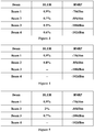
- Figure 3 shows a schematic example of selecting 2 candidate beams from among 4 beams.
- the BLER of each of the listed four beams is lower than the first threshold and are ranked in a descending order of the RSRP.
- N being equal to 2
- beam 1 and beam 2 are selected as candidate beams. It should be understood that Figure 3 is only a schematic example, and are not intended to limit the present disclosure.
- the selecting unit 102 is configured to select, from among beams of which the second quality indexes meet a second predetermined condition, one or more beams of which the first quality indexes meet a first predetermined condition and are optimal, as candidate beams. Still taking the first quality index BLER and the second quality index RSRP as an example, the selecting unit 102 selects, from among the beams of which the RSRPs are higher than the second threshold, the top N beams of which BLERs are lower than the first threshold and are the lowest, as candidate beams. For the schematic example shown in Figure 3 , the selecting unit 102 selects beam 3 and beam 4 with the lowest BLERs as candidate beams.
- the selecting unit 102 is configured to sequentially determine, in an order of beam quality indicated by the second quality index from high to low, whether the first quality index of each beam meets a first predetermined condition, with respect to beams of which the second quality indexes meet a second predetermined condition, and take a beam of which the first quality index meets the first predetermined condition as a candidate beam until the number of candidate beams reaches a requirement. Still taking the first quality index BLER and the second quality index RSRP as an example, the selecting unit 102 may calculate the BLER for the N beams with the highest RSRP among the beams of which RSRPs are higher than the second threshold. If the BLER is lower than the first threshold, the corresponding beam is taken as a candidate beam.
- Figure 4 is a schematic diagram showing a selection of candidate beams in this example. It may be seen that in a case that beam 1 and beam 2 meet the conditions, there is no need to calculate the BLERs of beam 3 and beam 4, thereby reducing calculation load.
- FIG. 5 is a schematic diagram showing a selection of candidate beams in this case. As shown in Figure 5 , since the BLER of beam 2 is higher than the threshold value of 1%, the BLER of beam 3 is continued to be calculated. The BLER of beam 3 is lower than the threshold, such that beam 1 and beam 3 are selected as candidate beams.
- the selecting unit 102 uses the first threshold for the first quality index in a case of selecting the candidate beams. Furthermore, the third threshold different from the first threshold may also be used to perform evaluation on beam quality based on the first quality index. In this case, the selecting unit 102 performs a selection of candidate beams by comparing the first quality index of the beam with the third threshold and comparing the second quality index of the beam with the second threshold.
- the beam quality represented by the third threshold may be better than the beam quality represented by the first threshold, and the beam quality represented by the second threshold may be better than the beam quality represented by the first threshold.
- the third threshold and the first threshold may be set to be equal, and the beam quality represented by the second threshold is better than the beam quality represented by the first threshold.
- the selecting unit 102 may select candidate beams with higher beam quality requirements, so as to improve the stability of the new beam after the beam failure recovery, thereby reducing a time delay.
- a gap value may be added on a basis of the first threshold for beam failure detection, which serves as the second threshold for candidate beam selection. For example, in a case that the first quality index and the second quality index both are BLER, the gap value is negative; in a case that the first quality index and the second quality index both are RSRP, the gap value is positive.
- the selecting unit 102 is further configured to set a timer when performing a selection of candidate beams, to perform detecting of the first quality index and the second quality index of the beam within a timing duration of the timer, and select the beam as a candidate beam in a case that the first quality index and the second quality index both meet the predetermined condition of serving as a candidate beam within the timing duration.
- the timing duration of the timer may be, for example, referred to as a candidate beam detection window. It may be understood that, in a case that the first quality index and the second quality index are different, timers with different timing durations may also be set for the first quality index and the second quality index, respectively.
- RRC Radio Resource Control
- the electronic apparatus performs selection of candidate beams based on two quality indexes including quality index used in beam failure detection, such that the occurrence of the ping-pong effect can be effectively avoided, thereby reducing the time delay.
- FIG. 6 is a block diagram showing functional modules of an electronic apparatus 200 for wireless communications according to another embodiment of the present disclosure.
- the electronic apparatus 200 includes: a first detecting unit 201, configured to perform detecting on beam quality of a currently serving beam, and determine that a beam failure occurs in a case of the beam quality being lower than a first quality; and a second detecting unit 202, configured to perform detecting on beam quality of another beam in a case of the beam failure occurring and select the beam as a candidate beam in a case of the beam quality being higher than a second quality, where the second quality is higher than the first quality.
- a first detecting unit 201 configured to perform detecting on beam quality of a currently serving beam, and determine that a beam failure occurs in a case of the beam quality being lower than a first quality
- a second detecting unit 202 configured to perform detecting on beam quality of another beam in a case of the beam failure occurring and select the beam as a candidate beam in a case of the beam quality being higher than a second quality, where
- first detecting unit 201 and the second detecting unit 202 may be implemented by one or more processing circuitries, the processing circuitries may be implemented, for example, as a chip. It should be noted that, functional units in the apparatus shown in Figure 6 only represent logic modules divided according to the implemented specific functions, and are not intended to limit the implementations. Similarly, the electronic apparatus 200 may be, for example, arranged at user equipment (UE) side, or may be communicatively connected to the UE.
- UE user equipment
- the beam quality of the candidate beam selected by the second detecting unit 202 is higher, such that the occurrence of the ping-pong effect can be avoided.
- the beam quality may be represented by BLER or RSRP.
- the representation of the beam quality used by the first detecting unit 201 and the representation of the beam quality used by the second detecting unit 202 may be the same or different.
- the second detecting unit 102 is further configured to set a timer when performing a selection of candidate beams, to perform detecting on the beam quality of the beam within a timing duration of the timer, and select the beam as the candidate beam in a case that the beam quality of the beam is higher than the second quality index within the timing duration.
- Figure 7 is a schematic diagram showing a selection of candidate beams in a case that BLER is used as an index of beam quality.
- a first threshold corresponds to the first quality
- a second threshold corresponds to the second quality
- the duration of the timer is referred to as a candidate beam detection window.
- Figure 8 is a schematic diagram showing a selection of candidate beams in a case of adopting RSRP as an index of beam quality.
- the second threshold is equivalent to the first threshold plus a gap.
- the gap value is negative; in a case that the quality indexes are RSRP, the gap value is positive.
- Information about the setting of one or more of the first quality, the second quality, the timing duration of the timer (that is, the size of the candidate beam detection window), and the gap value may be obtained from the base station via a Radio Resource Control (RRC) signaling.
- RRC Radio Resource Control
- the electronic apparatus and method according to this aspect of the present disclosure can effectively reduce the time delay caused by beam failure recovery and avoid the ping-pong effect, by selecting candidate beams with beam quality requirements that are higher than those required for beam failure detection.
- FIG. 9 is a block diagram showing functional modules of an electronic apparatus 300 for wireless communications according to another embodiment of the present disclosure.
- the electronic apparatus 300 includes: a detecting unit 301, configured to detect beam quality of a currently serving beam; and a predicting unit 302, configured to start a prediction window when the detected beam quality is within a particular range, and evaluate the beam quality of the currently serving beam within the prediction window.
- the detecting unit 301 and the predicting unit 302 may be implemented by one or more processing circuitries, and the processing circuitries may be implemented, for example, as a chip. It should be noted that, functional units in the apparatus shown in Figure 9 only represent logic modules divided according to the implemented specific functions, and are not intended to limit the implementations.
- the electronic apparatus 300 may be, for example, arranged at user equipment (UE) side or may be communicatively connected to the UE.
- the electronic apparatus 300 may be implemented in a chip level or a device level.
- the electronic apparatus 300 may function as the user equipment itself, and may also include external devices such as a memory, a transceiver (not shown in the figure), and the like.
- the memory may be configured to store program and related data information for implementing various functions by the user equipment.
- the transceiver may include one or more communication interfaces to support communication with various devices (for example, a base station, other UE and the like). The implementation of the transceiver is not limited here.
- the predicting unit 302 starts a prediction window, and continues to perform detecting on the beam quality of the currently serving beam in the prediction window, to evaluate or predict whether the currently serving beam would fail or get worse.
- the beam quality may be represented by one or more of the following: BLER, RSRP, and Reference Signal Receiving Quality (RSRQ) of the PDCCH.
- BLER BLER
- RSRP Reference Signal Receiving Quality
- RSRQ Reference Signal Receiving Quality
- multiple thresholds for beam quality may be set. In a case that the beam quality is lower than the worst beam quality indicated by the threshold, it indicates that a beam failure has occurred. In a case that the beam quality is higher than the worst beam quality indicated by the threshold but is lower than the beam quality required for maintaining high-quality communication, it is considered that the beam is getting worse, that is, the beam quality is poor but the link may work sometimes.
- a particular range is set as a range between two thresholds among the multiple thresholds for beam quality.
- the beam quality falls within the particular range, it means that the beam quality is getting worse and the prediction window is started.
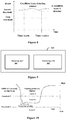
- Figure 10 shows an example of a case in which two thresholds are set, where the beam quality is represented by RSRP. It should be understood that this is not limitative, and other beam quality indexes may also be adopted.
- the beam quality is divided into three levels by threshold 1 and threshold 2, which are represented by level A, level B and level C.
- Level A indicates that the quality is the best, and at this level A, reliable communication may be maintained and the user experience is good; level B indicates that the quality is poor, and at this level B, communication where the user experience is poor may be performed; level C indicates that the quality is worst, and at this level C, communication cannot be performed.
- the beam quality is reduced to level C, it is considered that a beam failure has occurred.
- the prediction window is started, and the particular range includes an RSRP range corresponding to level B.
- Figure 11 shows an example of a case in which three thresholds are set.
- the beam quality is divided into three levels by threshold 1, threshold 2 and threshold 3.
- Level A indicates that the quality is best, and at this level A, reliable communication may be maintained and the user experience is good;
- level B indicates that the quality is relatively good, and at this level B, relatively good quality of communication may also be maintained;
- level C indicates that the quality is poor, and at this level C, communication where the user experience is poor may be performed;
- level D indicates that the quality is worst, and at this level D, communication cannot be performed.
- the beam quality is reduced to level D, it is considered that a beam failure has occurred.
- the prediction window is started, and the particular range includes an RSRP range corresponding to level C.
- the two thresholds defining the particular range include the one threshold indicating the worst beam quality among the multiple thresholds. In other words, if the beam quality falls within the particular range, it is indicated that the beam quality is getting worse and there is high possibility of beam failure occurring. Accordingly, the predicting unit 302 continues to evaluate in the prediction window to determine whether the beam deterioration is an accidental event or an indication that beam switching is required.
- the predicting unit 302 is configured to determine, in a case that the number of events of detecting the beam quality to be within the particular range in the prediction window exceeds a predetermined value, that the beam quality of the currently serving beam is poor, and generate a beam switching request such as Beam_Switch_request to be transmitted to a base station, that is, a beam switching procedure is started.
- the detection is regarded as an event of detecting a poor beam, and these events are counted in the prediction window.
- the counting value exceeds a predetermined value, it is considered that the beam quality is getting quite bad and it is required to switch to a beam with better beam quality to continue communication.
- the predicting unit 302 when it is detected that the beam quality falls below the worst beam quality indicated by the threshold (for example, the beam quality falls to the level C in the example of Figure 10 or falls to the level D in the example of Figure 11 ), the predicting unit 302 generates a beam failure recovery request to be transmitted to the base station, that is, a beam failure recovery procedure is started.
- Figure 12 is another block diagram showing functional modules of the electronic apparatus 300. Besides the detecting unit 301 and the predicting unit 302, the electronic apparatus 300 further includes a switching unit 303, configured to perform operations related to beam switching.
- a switching unit 303 configured to perform operations related to beam switching.
- the switching unit 303 is configured to detect beam quality of other beams in a case of the predicting unit 302 determining the beam quality of the currently serving beam being poor, to select one or more candidate beams as a switching target, and the predicting unit 302 contains the information about the selected candidate beams in the beam switching request.
- the beam switching request may further include an identification of the currently serving beam and beam quality information.
- the beam quality of the candidate beam is higher than the upper limit of the beam quality indicated by the particular range; and the beam quality of the candidate beam is higher than the beam quality corresponding to the threshold for beam failure detection by a predetermined value.
- the switching unit 303 is further configured to start a beam switching window after the beam switching request is transmitted, and monitor a beam switching request response (such as Beam_Switch_request_Response) from a base station in the beam switching window.
- the beam switching request response includes, for example, one or more of the following: confirmation of the beam switching request; the time to perform the beam switching, that is, the base station and the UE switch to the new beam at the same time after a certain period of time; and information about an ID of the new beam to be switched to, and the like.
- the beam switching request and the beam switching request response may be transmitted on the currently serving beam.
- Information about one or more of the various parameters used in the above operations may be obtained via an RRC signaling, for example, such parameters include: multiple thresholds for beam quality; a particular range; a size of a prediction window; the number of events of beam quality being within the particular range; and the number of candidate beams reported in the beam switching request, and the like.
- the predicting unit 302 is configured to perform a predetermined number of times of detections on the beam quality of the currently serving beam in the prediction window, record a detection value of each of multiple detections, and predict whether the currently serving beam fails based on the recorded detection values.
- the predetermined number of times may be configured by the base station.
- the predicting unit 302 observes a change tendency of the beam quality by recording the detection values of multiple detections to predict whether a beam failure will occur.
- Figure 13 is a schematic diagram showing N times of detection of beam quality.
- the predicting unit 302 is configured to determine a change tendency of the beam quality of the currently serving beam by comparing the ratio of a subsequent detection value to a previous detection value with a particular parameter, to perform the prediction, where the particular parameter is related to an upper limit and a lower limit of the particular range as well as the predetermined number of times.
- t t 2 t 1 1 N ⁇ 1
- t1 represents an upper limit of the particular range, such as threshold 1 in Figure 10
- t2 represents a lower limit of the particular range, such as threshold 2 in Figure 10 .
- the reason is that, if the beam quality continuously decreases from threshold 1 to threshold 2 within N detection periods, the detection values of the beam quality may be treated as a geometric sequence.
- ⁇ represents a fixed value fine-adjusted on the basis of t2, which is positive value in a case that RSRP is used.
- the predicting unit 302 is further configured to count comparisons with a consistent change tendency, and predict that the currently serving beam will fail when the counting reaches a predetermined number of times. For example, in the above example, the comparison of Q i Q i ⁇ 1 ⁇ t would be counted, and in a case that the counting reaches N, it is predicted that the currently serving beam will fail, and a beam failure recovery request may be transmitted to the base station.
- the predicting unit 302 is further configured to adjust the predetermined number of times in a case of the change tendency being inconsistent, and predict that the currently serving beam will fail when the counting reaches the adjusted predetermined number of times.
- the predicting unit 302 may add the following value to the predetermined number of times to perform adjustment: a difference between a sequence number of the previous detection value corresponding to the comparison with the inconsistent change tendency and a sequence number of a preceding proximity detection value of the previous detection value, wherein the preceding proximity detection value is, in a case that the subsequent detection value corresponding to the comparison with the inconsistent change tendency is contained within a range between the subsequent detection value and the previous detection value for which comparison has been performed, the previous detection value of the subsequent detection value and the previous detection value for which comparison has been performed.
- the predicting unit 302 will close the prediction window, and does not perform prediction and evaluation on the beam quality any longer.
- Figure 14 shows a flowchart of an example of operations performed by the predicting unit in this example.
- the detection value shown in Figure 13 is still taken as an example.
- step S11 beam quality of a currently serving beam is detected, and in step S12, it is determined whether the beam quality falls below the threshold value 1. If it is determined that the beam quality falls below the threshold value 1, the prediction window is started, and the processing proceeds to step S13.
- step S13 Q i Q i ⁇ 1 is calculated and it is determined whether Q i Q i ⁇ 1 ⁇ t is met, and if it is determined that Q i Q i ⁇ 1 ⁇ t is met, the processing proceeds to step S14, where the parameter i and count are incremented by 1 respectively (where the initial value of count is 0).
- step S15 it is determined whether the updated count reaches a predetermined number of times N. If the updated count reaches a predetermined number of times N, it is determined that a beam failure has occurred, and then, the processing proceeds to step S19 to transmit a beam failure recovery request to the base station. If it is determined in step S15 that the updated count does not reach a predetermined number of times N, the processing returns to step S13 to continue counting.
- step S13 if it is determined in step S13 that Q i Q i ⁇ 1 ⁇ t is not met, the processing proceeds to step S16.
- step S16 Q i is compared with the preceding Q i -1 , Q i -2 , ..., Q 1 . If Q i falls between Q m and Q m +1 , that is, there is such m, steps S17 and step S18 are performed, where the parameter i and count are incremented by 1, respectively, and N is changed to be N+i-m.
- the initial N is equal to 4, Q i Q i ⁇ 1 ⁇ t is met in the first two comparisons, and in a case that the parameter i is equal to 4, the beam quality suddenly increases to a value between Q 1 and Q 2 .
- N may be adjusted for multiple times.
- a maximum value N max may be set for N. In a case that N>N max is met, the prediction window is closed and the procedure ends.
- step S16 if such m is not found in step S16, it means that Q i becomes higher than the threshold value 1. In this case, the prediction window is closed, and the procedure ends.
- the above description is given by taking RSRP as the beam quality index, and the above description is also applicable to other beam quality indexes such as BLER, and only some comparison rules are required to be adjusted. Furthermore, although not specifically described in this embodiment, as described in the first embodiment and second embodiment, when it is determined that a beam failure occurs, the UE side also needs to perform a selection of candidate beams and contain the related information about the candidate beams in the transmitted beam failure recovery request.
- Information about one or more of the various parameters used in the above operations may be obtained via an RRC signaling, such parameters include: multiple thresholds for beam quality; a particular range; a size of a prediction window; the predetermined number of times N of detecting the beam quality in the prediction window; the maximum value of the adjusted predetermined number of times N; the number of candidate beams reported in the beam switching request, and the like.
- the electronic apparatus and a method according to this embodiment may pre-evaluate the beam quality of the currently serving beam by setting the prediction window, so as to quickly determine switching operation and recovery operation to be performed, thereby reducing the time delay.
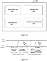
- Figure 16 shows a block diagram of functional modules of an electronic apparatus 400 for wireless communications according to an embodiment of the present disclosure.
- the electronic apparatus 400 includes: a determining unit 401, configured to determine, based on information about a tail window contained in a beam failure recovery request response from a base station, a size of the tail window to be opened; and a detecting unit 402, configured to open the tail window and detect beam quality of a new beam in the tail window.
- the determining unit 401 and the detecting unit 402 may be implemented by one or more processing circuitries, and the processing circuitries may be implemented, for example, as a chip. It should be noted that, functional units in the apparatus shown in Figure 16 only represent logic modules divided according to the implemented specific functions, and are not intended to limit the implementations.
- the electronic apparatus 400 may be, for example, arranged at user equipment (UE) side, or may be communicatively connected to the UE.
- the electronic apparatus 400 may be implemented in a chip level or in a device level.
- the electronic apparatus 400 may function as the UE itself, and may further include external devices such as a memory and a transceiver (not shown in the figure).
- the memory may be configured to store program and related data information for implementing various functions by the user equipment.
- the transceiver may include one or more communication interfaces to support communication with various devices (for example a base station, other UE and the like). The implementation of the transceiver is not limited here.
- the new beam after the beam failure recovery may fail again within a short time period, that is, the beam quality falls below the beam failure detection threshold.
- the beam failure recovery mechanism is required to be triggered again, and the UE needs to wait for the same long beam recovery time delay, which will result in poor user experience.
- the concept of a tail window is proposed. Specifically, in a case that the beam recovery is successful, for example, the beam quality of the new beam reaches a level at which the new beam may operate normally, the new beam is still monitored for a period of time, which is referred to as a tail window. If a beam failure occurs again in the tail window, a quicker beam recovery mechanism will be triggered.
- the electronic apparatus 400 further includes: a generating unit 403, configured to generate a beam failure recovery request when the number of times of detecting that beam quality of a currently serving beam is lower than a predetermined threshold exceeds a first number of times; and generate a new beam failure recovery request when the number of times of detecting that the beam quality of the new beam is lower than a predetermined threshold exceeds a second number of times in the tail window, wherein the first number of times is greater than the second number of times.
- a generating unit 403 configured to generate a beam failure recovery request when the number of times of detecting that beam quality of a currently serving beam is lower than a predetermined threshold exceeds a first number of times
- a new beam failure recovery request when the number of times of detecting that the beam quality of the new beam is lower than a predetermined threshold exceeds a second number of times in the tail window, wherein the first number of times is greater than the second number of times.
- the generating unit 401 sets a different M for the case in which the beam failure occurs for the first time and for the case in which the beam failure occurs again in the tail window after the beam failure recovery, where a smaller M is set for the case in which the beam failure occurs again in the tail window, thereby reducing the time delay of beam recovery in the case of the beam failure occurring frequently. It should be understood that when beam failure recovery occurs consecutively for multiple times, M may be reduced for each time, that is, M used for the subsequent beam failure detection is smaller than M used for the previous beam failure detection until the specified minimum value of M is reached.
- the electronic apparatus 400 further includes a response monitoring unit 404, configured to open a beam failure recovery window with a first size after the beam failure recovery request is transmitted, to wait for the beam failure recovery request response; and open a beam failure recovery window with a second size after the new beam failure recovery request is transmitted, to wait for the beam failure recovery request response, wherein the first size is greater than the second size.
- a response monitoring unit 404 configured to open a beam failure recovery window with a first size after the beam failure recovery request is transmitted, to wait for the beam failure recovery request response; and open a beam failure recovery window with a second size after the new beam failure recovery request is transmitted, to wait for the beam failure recovery request response, wherein the first size is greater than the second size.
- the UE monitors the response from the base station within a certain period of time, which may be referred to as a beam failure recovery window.
- the response monitoring unit 404 opens beam failure recovery windows with different sizes for the case in which the beam failure occurs for a first time and for the case in which the beam failure occurs again in the tail window, where a beam failure recovery window with a smaller size is opened for the case in which the beam failure occurs again in the tail window, thereby reducing the time delay of beam recovery in the case of the beam failure occurring frequently.
- the first size and the second size can be in units of slot, and the first size and the second size may be set by the base station.
- the size of the beam failure recovery window may be reduced for each time, that is, the size of the beam failure recovery window used for the subsequent beam failure recovery is smaller than the size of the beam failure recovery window used for the previous beam failure recovery, until the specified minimum value of the size of the beam failure recovery window is reached.
- Figure 17 shows an example of a tail window.
- BFRQ beam failure recovery request
- the second beam failure recovery in a case that M2 consecutive beam failure events are detected in the phase of the beam failure detection, it is considered that beam failure occurs and a BFRQ is transmitted to the base station, where M2 ⁇ M1. Furthermore, the size of the beam failure recovery window used to monitor and receive the BFRQ response from the base station is also reduced to T2ms, where T2 ⁇ T1. Although not shown in Figure 17 , it should be understood that after the second beam failure recovery is completed, the tail window may be continued to be opened, and M2 and T2 are further reduced.
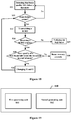
- Figure 18 shows a schematic flowchart of a tail window mechanism of this embodiment.
- UE detects beam quality and determines that the beam quality falls below a threshold in step S21, and then, in step S22, the UE determines whether beam failure occurs, that is, whether the number of beam failure events exceeds the maximum number M of beam failure events. If it is determined that the number of beam failure events does not exceed the maximum number M of beam failure events, the processing returns to step S21 to continue the detection, otherwise, the processing proceeds to step S23 to transmit a BFRQ to the base station. Next, in step S24, it is determined whether a BFRQ response from the base station is received in the beam failure recovery window.
- step S27 the processing proceeds to step S27 to notify the higher layer to perform additional processing. If the BFRQ response is received, the processing proceeds to step S25, and in step S25, the tail window is opened and it is monitored in the tail window whether the beam quality of the new beam falls below the threshold. If the beam quality of the new beam does not fall below the threshold, the processing proceeds to step S28 and the beam recovery is successful. If the beam quality of the new beam falls below the threshold, the maximum number M of beam failure events and the size T of the beam failure recovery window in beam failure detection are changed, and the processing returns to step S22 to perform beam failure detection. Then, the following steps are repeated.
- the generating unit 403 is further configured to generate a tail window opening request (such as Open_Tail_Window_Request) to be transmitted to the base station simultaneously with the beam failure recovery request. That is, the setting information of the tail window may be transmitted in response to the request of the UE.
- the information about the tail window from the base station may include, for example, one or more of the following: an indication of opening the tail window; the size of the tail window; the maximum number of beam failure events; the size of the beam failure recovery window in the tail window, and the like.
- the electronic apparatus and the method according to the aspect of the present disclosure may quickly perform beam recovery in a case that the new beam fails again by detecting the beam quality of the new beam in the tail window, thereby reducing the time delay.
- Figure 19 is a block diagram showing functional modules of an electronic apparatus 500 for wireless communications according to another embodiment of the present disclosure.
- the electronic apparatus 500 includes: a first generating unit 501, configured to generate configuration for beam failure recovery operation of user equipment and contain the configuration in a radio resource control signaling to be provided to the user equipment; and a second generating unit 502, configured to generate a beam failure recovery request response in response to a beam failure recovery request from the user equipment, where the configuration includes one or more of the following: multiple beam quality thresholds for beam quality evaluation, a first beam quality threshold and a second beam quality threshold for candidate beam selection, a duration of a timer for candidate beam selection, a size of a prediction window for beam quality evaluation.
- the first generating unit 501 and the second generating unit 502 may be implemented by one or more processing circuitries, and the processing circuitries may be implemented, for example, as a chip. It should be noted that, functional units in the apparatus shown in Figure 19 only represent logic modules divided according to the implemented specific functions, and are not intended to limit the implementations.
- the electronic apparatus 500 may be, for example, arranged at a base station side, or may be communicatively connected to the base station.
- the electronic apparatus 500 may be implemented in a chip level or in a device level.
- the electronic apparatus 500 may functions as the base station itself, and may further include external devices such as a memory and a transceiver (not shown in the figure).
- the memory may be configured to store program and related data information for implementing various functions by the base station.
- the transceiver may include one or more communication interfaces to support communication with various devices (for example, user equipment, other base stations and the like). The implementation of the transceiver is not limited here.
- the electronic apparatus 500 may provide an RRC configuration signaling and a beam failure recovery request (BFRQ) response corresponding to one or more of the electronic apparatuses 100 to 400 according to the foregoing embodiments.
- BFRQ beam failure recovery request
- the configuration of the RRC regarding the beam failure recovery operation has been described in detail in the first embodiment to the fourth embodiment, which is not repeated here.
- the second generating unit 502 is further configured to generate a beam switching request response for a beam switching request from the user equipment.
- the beam switching request response includes, for example, confirmation of the beam switching request or information about an ID of the new beam to be switched to.
- the second generating unit 502 may also include information about a size of a tail window in the beam failure recovery request response, and the user equipment detects beam quality of a new beam in the tail window.
- the electronic apparatus and the method according to this embodiment may achieve high-efficiency, low-latency beam failure recovery by configuring the beam failure recovery operation of the user equipment.
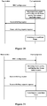
- Figure 20 shows an information procedure for beam switching between a base station and user equipment
- the base station transmits an RRC configuration to the user equipment.
- the RRC configuration may include a size of a prediction window related to beam switching, the setting of multiple thresholds and the like.
- the UE performs detecting on the beam quality based on the configuration and determines that the beam quality falls within a particular range defined by the thresholds. In this case, the UE opens a prediction window. If it is detected that a beam becomes a poor beam in the prediction window, a beam switching request is transmitted to the base station.
- the beam switching request may include information about a candidate beam as a switching target such as an ID and beam quality thereof, and may also include an ID and beam quality of the current poor beam.
- the base station transmits a beam switching request response to the user equipment, which includes confirmation of the beam switching request.
- the user equipment switches to the candidate beam based on the beam switching request response.
- Figure 21 shows an information procedure for beam recovery between a base station and user equipment.
- the base station transmits an RRC configuration to the user equipment.
- the RRC configuration may include parameters related to beam failure detection, parameters related to selection of candidate beams, and may also include the above parameters related to beam switching.
- the UE performs detecting on the beam quality based on this configuration and determines that beam failure occurs or predicts that beam failure will occur (for example, adopting the scheme in the third embodiment).
- the UE transmits a beam failure recovery request to the base station, which may include information about candidate beam such as an ID and beam quality thereof and the like.
- the base station transmits a beam failure recovery request response to the user equipment, which includes confirmation of the beam failure recovery request.
- the user equipment switches to the candidate beam based on the beam failure recovery request response.
- Figure 22 also shows a diagram of an example of an information procedure between the base station and the user equipment in the case that a tail window is provided.
- the user equipment also transmits a tail window opening request to the base station when transmitting the BFRQ, and the base station transmits a BFRQ response to the user equipment in response to these requests.
- the user equipment switches to a new beam, and detects beam quality of the new beam in the tail window. If it is determined that the beam failure occurs again, the user equipment transmits a BFRQ and a tail window opening request, and receives a BFRQ response from the base station. The processing is performed repetitively.
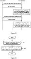
- Figure 23 is a flowchart showing a method for wireless communications according to an embodiment of the present disclosure.
- the method includes: performing beam failure detection on a currently serving beam using a first quality index of a beam (S31); and selecting a candidate beam from among other beams using the first quality index of the beam and a second quality index of the beam which is different from the first quality index, the candidate beam being used for beam recovery after beam failure (S32).
- This method adopts two quality indexes in a case of selecting candidate beams, such that in a case that the beam quality index used for beam failure detecting and the beam quality index used for candidate beam selecting are different, a ping-pong effect is avoided, thereby reducing the time delay of beam failure recovery.
- This method corresponds to the apparatus 100 described in the first embodiment. For specific details, one may refer to the above corresponding description, and details are not repeated here.
- Figure 24 shows a method for wireless communications according to another embodiment of the present disclosure.
- the method includes: performing detecting on beam quality of a currently serving beam, and determining that a beam failure occurs in a case of the beam quality being lower than a first quality (S41); and in a case of the beam failure occurring, performing detecting on beam quality of another beam, and taking the beam as a candidate beam in a case of the beam quality being higher than a second quality (S42), where the second quality is higher than the first quality.
- S41 first quality
- S42 second quality
- This method may avoid the occurrence of ping-pong effect by appropriately increasing the threshold for beam quality in a case of selecting candidate beams, thereby reducing the time delay of beam failure recovery.
- This method corresponds to the apparatus 200 described in the second embodiment. For specific details, one may refer to the above corresponding description, and details are not repeated here.
- Figure 25 shows a method for wireless communications according to another embodiment of the present disclosure.
- the method includes: detecting beam quality of a currently serving beam (S51); and starting a prediction window when the detected beam quality is within a particular range, and evaluating the beam quality of the currently serving beam within the prediction window (S52).
- This method may predict a beam failure which may occur in a case that the beam quality of the serving beam falls to a certain degree by setting a prediction window, so as to timely perform beam switching or beam recovery, thereby reducing the time delay.
- This method corresponds to the apparatus 300 described in the third embodiment. For specific details, one may refer to the above corresponding description, and details are not repeated here.
- Figure 26 shows a method for wireless communications according to another embodiment of the present disclosure.
- the method includes: determining, based on information about a tail window contained in a beam failure recovery request response from a base station, a size of the tail window to be opened (S61); and opening the tail window and detecting beam quality of the new beam in the tail window (S62).
- This method implements quick recovery of beam failures which occurs frequently by setting a tail window, thereby reducing the time delay.
- This method corresponds to the apparatus 400 described in the fourth embodiment. For specific details, one may refer to the above corresponding description, and details are not repeated here.
- Figure 27 shows a method for wireless communications according to another embodiment of the present disclosure.
- the method includes: generating a configuration for beam failure recovery operation of user equipment and containing the configuration in an RRC signaling to be provided to the user equipment (S71); and generating a beam failure recovery request response in response to a beam failure recovery request from the user equipment (S72), where the configuration includes one or more of the following: multiple beam quality thresholds for beam quality evaluation, a first beam quality threshold and a second beam quality threshold for candidate beam selection, a duration of a timer for candidate beam selection, a size of a prediction window for beam quality evaluation.
- This method may achieve high-efficiency, low-latency beam failure recovery by configuring the beam failure recovery operation of the user equipment.
- This method corresponds to the apparatus 500 described in the fifth embodiment. For specific details, one may refer to the above corresponding description, and details are not repeated here.
- the technology according to the present disclosure is applicable to various products.
- the electronic apparatus 500 may be implemented as various base stations.
- the base station may be implemented as any type of evolution Node B (eNB) or gNB (which is a 5G base station).
- the eNB includes, for example, a macro eNB and a small eNB.
- the small eNB may be an eNB that covers a cell smaller than a macro cell, such as a pico eNB, a micro eNB and a home (femto) eNB.
- the case for the gNB is similar to the above.
- the base station may be implemented as any other type of base station, such as a NodeB and a base transceiver station (BTS).
- BTS base transceiver station
- the base station may include a body (also referred to as a base station device) configured to control wireless communications; and one or more remote radio heads (RRH) arranged in a different position from the body.
- a body also referred to as a base station device
- RRH remote radio heads
- various types of user equipments may each operate as the base station by temporarily or semi-persistently executing a base station function.
- the user equipment may be implemented as a mobile terminal (such as a smartphone, a tablet personal computer (PC), a notebook PC, a portable game terminal, a portable/dongle type mobile router, and a digital camera device), or an in-vehicle terminal (such as a vehicle navigation device).
- the user equipment may also be implemented as a terminal that performs machine-to-machine (M2M) communication (which is also referred to as a machine type communication (MTC) terminal).
- M2M machine-to-machine
- MTC machine type communication
- the user equipment may be a wireless communication module (such as an integrated circuit module including a single chip) mounted on each of the above terminals.
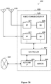
- FIG 28 is a block diagram showing a first example of a schematic configuration of an eNB or a gNB to which the technology of the present disclosure may be applied. It should be noted that the following description is given by taking the eNB as an example, which is also applicable to the gNB.
- An eNB 800 includes one or more antennas 810 and a base station apparatus 820. The base station apparatus 820 and each of the antennas 810 may be connected to each other via a radio frequency (RF) cable.
- RF radio frequency
- Each of the antennas 810 includes a single or multiple antennal elements (such as multiple antenna elements included in a multiple-input multiple-output (MIMO) antenna), and is used for the base station apparatus 820 to transmit and receive wireless signals.
- the eNB 800 may include the multiple antennas 810.
- the multiple antennas 810 may be compatible with multiple frequency bands used by the eNB 800.
- Figure 28 shows the example in which the eNB 800 includes the multiple antennas 810, the eNB 800 may also include a single antenna 810.
- the base station apparatus 820 includes a controller 821, a memory 822, a network interface 823, and a radio communication interface 825.
- the controller 821 may be, for example, a CPU or a DSP, and operates various functions of a higher layer of the base station apparatus 820. For example, the controller 821 generates a data packet from data in signals processed by the radio communication interface 825, and transfers the generated packet via the network interface 823. The controller 821 may bundle data from multiple base band processors to generate the bundled packet, and transfer the generated bundled packet. The controller 821 may have logical functions of performing control such as radio resource control, radio bearer control, mobility management, admission control and scheduling. The control may be performed in corporation with an eNB or a core network node in the vicinity.
- the memory 822 includes a RAM and a ROM, and stores a program executed by the controller 821 and various types of control data (such as terminal list, transmission power data and scheduling data).
- the network interface 823 is a communication interface for connecting the base station apparatus 820 to a core network 824.
- the controller 821 may communicate with a core network node or another eNB via the network interface 823.
- the eNB 800, and the core network node or another eNB may be connected to each other via a logic interface (such as an S1 interface and an X2 interface).
- the network interface 823 may also be a wired communication interface or a wireless communication interface for wireless backhaul. If the network interface 823 is a wireless communication interface, the network interface 823 may use a higher frequency band for wireless communication than that used by the radio communication interface 825.
- the radio communication interface 825 supports any cellular communication scheme (such as Long Term Evolution (LTE) and LTE-advanced), and provides wireless connection to a terminal located in a cell of the eNB 800 via the antenna 810.
- the radio communication interface 825 may typically include, for example, a baseband (BB) processor 826 and an RF circuit 827.
- the BB processor 826 may perform, for example, encoding/decoding, modulating/demodulating, and multiplexing/demultiplexing, and performs various types of signal processing of layers (such as L1, Media Access Control (MAC), Radio Link Control (RLC), and a Packet Data Convergence Protocol (PDCP)).
- L1, Media Access Control (MAC), Radio Link Control (RLC), and a Packet Data Convergence Protocol (PDCP) such as L1, Media Access Control (MAC), Radio Link Control (RLC), and a Packet Data Convergence Protocol (PDCP)
- the BB processor 826 may have a part or all of the above-described logical functions instead of the controller 821.
- the BB processor 826 may be a memory storing communication control programs, or a module including a processor and a related circuit configured to execute the programs. Updating the program may allow the functions of the BB processor 826 to be changed.
- the module may be a card or a blade that is inserted into a slot of the base station apparatus 820. Alternatively, the module may also be a chip that is mounted on the card or the blade.
- the RF circuit 827 may include, for example, a mixer, a filter, and an amplifier, and transmits and receives wireless signals via the antenna 810.
- the radio communication interface 825 may include the multiple BB processors 826.
- the multiple BB processors 826 may be compatible with multiple frequency bands used by the eNB 800.
- the radio communication interface 825 may include multiple RF circuits 827, as shown in Figure 28 .
- the multiple RF circuits 827 may be compatible with multiple antenna elements.
- Figure 28 shows the example in which the radio communication interface 825 includes the multiple BB processors 826 and the multiple RF circuits 827, the radio communication interface 825 may also include a single BB processor 826 and a single RF circuit 827.
- the transceiver of the electronic apparatus 500 may be implemented by the radio communication interface 825. At least a part of the functions may also be implemented by the controller 821.
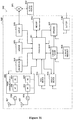
- the controller 821 may generate an RRC signaling for the user equipment which includes configuration for a beam failure recovery operation and generate a BFRQ response, by performing functions of the first generating unit 501 and the second generating unit 502.
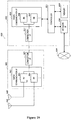
- FIG. 29 is a block diagram showing a second example of a schematic configuration of an eNB or a gNB to which the technology according to the present disclosure may be applied. It should be noted that the following description is given by taking the eNB as an example, which is also applied to the gNB.
- An eNB 830 includes one or more antennas 840, a base station apparatus 850, and an RRH 860.
- the RRH 860 and each of the antennas 840 may be connected to each other via an RF cable.
- the base station apparatus 850 and the RRH 860 may be connected to each other via a high speed line such as an optical fiber cable.
- Each of the antennas 840 includes a single or multiple antennal elements (such as multiple antenna elements included in an MIMO antenna), and is used for the RRH 860 to transmit and receive wireless signals.
- the eNB 830 may include the multiple antennas 840.
- the multiple antennas 840 may be compatible with multiple frequency bands used by the eNB 830.
- Figure 29 shows the example in which the eNB 830 includes the multiple antennas 840, the eNB 830 may also include a single antenna 840.
- the base station apparatus 850 includes a controller 851, a memory 852, a network interface 853, a radio communication interface 855, and a connection interface 857.
- the controller 851, the memory 852, and the network interface 853 are the same as the controller 821, the memory 822, and the network interface 823 described with reference to Figure 28 .
- the radio communication interface 855 supports any cellular communication scheme (such as LTE and LTE-advanced), and provides wireless communication to a terminal located in a sector corresponding to the RRH 860 via the RRH 860 and the antenna 840.
- the radio communication interface 855 may typically include, for example, a BB processor 856.
- the BB processor 856 is the same as the BB processor 826 described with reference to Figure 28 , except that the BB processor 856 is connected to an RF circuit 864 of the RRH 860 via the connection interface 857.
- the radio communication interface 855 may include the multiple BB processors 856.
- the multiple BB processors 856 may be compatible with multiple frequency bands used by the eNB 830.
- Figure 29 shows the example in which the radio communication interface 855 includes the multiple BB processors 856, the radio communication interface 855 may also include a single BB processor 856.
- connection interface 857 is an interface for connecting the base station apparatus 850 (radio communication interface 855) to the RRH 860.
- the connection interface 857 may also be a communication module for communication in the above-described high speed line that connects the base station apparatus 850 (radio communication interface 855) to the RRH 860.
- the RRH 860 includes a connection interface 861 and a radio communication interface 863.
- connection interface 861 is an interface for connecting the RRH 860 (radio communication interface 863) to the base station apparatus 850.
- the connection interface 861 may also be a communication module for communication in the above-described high speed line.
- the radio communication interface 863 transmits and receives wireless signals via the antenna 840.
- the radio communication interface 863 may typically include, for example, the RF circuit 864.
- the RF circuit 864 may include, for example, a mixer, a filter and an amplifier, and transmits and receives wireless signals via the antenna 840.
- the radio communication interface 863 may include multiple RF circuits 864, as shown in Figure 29 .
- the multiple RF circuits 864 may support multiple antenna elements.
- Figure 29 shows the example in which the radio communication interface 863 includes the multiple RF circuits 864, the radio communication interface 863 may also include a single RF circuit 864.
- the transceiver of the electronic apparatus 500 may be implemented by the radio communication interface 825. At least a part of the functions may also be implemented by the controller 821.
- the controller 821 may generate an RRC signaling for the user equipment which includes configuration for a beam failure recovery operation and generate a BFRQ response, by performing functions of the first generating unit 501 and the second generating unit 502.
- FIG 30 is a block diagram illustrating an example of exemplary configuration of a smartphone 900 to which the technology of the present disclosure may be applied.
- the smartphone 900 includes a processor 901, a memory 902, a storage 903, an external connection interface 904, a camera 906, a sensor 907, a microphone 908, an input device 909, a display device 910, a speaker 911, a radio communication interface 912, one or more antenna switches 915, one or more antennas 916, a bus 917, a battery 918, and an auxiliary controller 919.
- the processor 901 may be, for example, a CPU or a system on a chip (SoC), and controls functions of an application layer and another layer of the smartphone 900.
- the memory 902 includes a RAM and a ROM, and stores a program executed by the processor 901 and data.
- the storage 903 may include a storage medium such as a semiconductor memory and a hard disk.
- the external connection interface 904 is an interface for connecting an external device (such as a memory card and a universal serial bus (USB) device) to the smartphone 900.
- the camera 906 includes an image sensor (such as a charge coupled device (CCD) and a complementary metal oxide semiconductor (CMOS)), and generates a captured image.
- the sensor 907 may include a group of sensors, such as a measurement sensor, a gyro sensor, a geomagnetism sensor, and an acceleration sensor.
- the microphone 908 converts sounds that are inputted to the smartphone 900 to audio signals.
- the input device 909 includes, for example, a touch sensor configured to detect touch onto a screen of the display device 910, a keypad, a keyboard, a button, or a switch, and receives an operation or information inputted from a user.
- the display device 910 includes a screen (such as a liquid crystal display (LCD) and an organic light-emitting diode (OLED) display), and displays an output image of the smartphone 900.
- the speaker 911 converts audio signals that are outputted from the smartphone 900 to sounds.
- the radio communication interface 912 supports any cellular communication scheme (such as LTE and LTE-advanced), and performs a wireless communication.
- the radio communication interface 912 may include, for example, a BB processor 913 and an RF circuit 914.
- the BB processor 913 may perform, for example, encoding/decoding, modulating/demodulating, and multiplexing/de-multiplexing, and perform various types of signal processing for wireless communication.
- the RF circuit 914 may include, for example, a mixer, a filter and an amplifier, and transmits and receives wireless signals via the antenna 916.
- the radio communication interface 912 may be a chip module having the BB processor 913 and the RF circuit 914 integrated thereon.
- the radio communication interface 912 may include multiple BB processors 913 and multiple RF circuits 914, as shown in Figure 30 .
- Figure 30 shows the example in which the radio communication interface 912 includes the multiple BB processors 913 and the multiple RF circuits 914, the radio communication interface 912 may also include a single BB processor 913 or a single RF circuit 914.
- the radio communication interface 912 may support another type of wireless communication scheme such as a short-distance wireless communication scheme, a near field communication scheme, and a radio local area network (LAN) scheme.
- the radio communication interface 912 may include the BB processor 913 and the RF circuit 914 for each wireless communication scheme.
- Each of the antenna switches 915 switches connection destinations of the antennas 916 among multiple circuits (such as circuits for different wireless communication schemes) included in the radio communication interface 912.
- Each of the antennas 916 includes a single or multiple antenna elements (such as multiple antenna elements included in an MIMO antenna) and is used for the radio communication interface 912 to transmit and receive wireless signals.
- the smartphone 900 may include the multiple antennas 916, as shown in Figure 30 . Although Figure 30 shows the example in which the smartphone 900 includes the multiple antennas 916, the smartphone 900 may also include a single antenna 916.
- the smartphone 900 may include the antenna 916 for each wireless communication scheme.
- the antenna switches 915 may be omitted from the configuration of the smartphone 900.
- the bus 917 connects the processor 901, the memory 902, the storage 903, the external connection interface 904, the camera 906, the sensor 907, the microphone 908, the input device 909, the display device 910, the speaker 911, the radio communication interface 912, and the auxiliary controller 919 to each other.
- the battery 918 supplies power to blocks of the smart phone 900 shown in Figure 30 via feeder lines that are partially shown as dashed lines in Figure 30 .
- the auxiliary controller 919 operates a minimum necessary function of the smart phone 900, for example, in a sleep mode.
- the transceiver of the electronic apparatuses 100 to 400 may be implemented by the radio communication interface 912. At least a part of the functions may be implemented by the processor 901 or the auxiliary controller 919.
- the controller 901 or the auxiliary controller 919 may implement beam failure detection and selection of candidate beams by performing functions of the beam failure detecting unit 101 and the selecting unit 102, to avoid ping-pong effect.
- the controller 901 or the auxiliary controller 919 may take a beam with a high beam quality as a candidate beam by performing functions of the first detecting unit 201 and the second detecting unit 202.
- the controller 901 or the auxiliary controller 919 may implement a prediction of beam failure and a beam switching by performing functions of the detecting unit 301, the predicting unit 302 and the switching unit 303.
- the controller 901 or the auxiliary controller 919 may implement a tail window mechanism by performing functions of the determining unit 401, the detecting unit 402, the generating unit 403 and the response monitoring unit 404.
- FIG 31 is a block diagram showing an example of a schematic configuration of a car navigation apparatus 920 to which the technology according to the present disclosure may be applied.
- the car navigation apparatus 920 includes a processor 921, a memory 922, a global positioning system (GPS) module 924, a sensor 925, a data interface 926, a content player 927, a storage medium interface 928, an input device 929, a display device 930, a speaker 931, a radio communication interface 933, one or more antenna switches 936, one or more antennas 937, and a battery 938.
- GPS global positioning system
- the processor 921 may be, for example a CPU or a SoC, and controls a navigation function and additional function of the car navigation apparatus 920.
- the memory 922 includes RAM and ROM, and stores a program that is executed by the processor 921, and data.
- the GPS module 924 determines a position (such as latitude, longitude and altitude) of the car navigation apparatus 920 by using GPS signals received from a GPS satellite.
- the sensor 925 may include a group of sensors such as a gyro sensor, a geomagnetic sensor and an air pressure sensor.
- the data interface 926 is connected to, for example, an in-vehicle network 941 via a terminal that is not shown, and acquires data (such as vehicle speed data) generated by the vehicle.
- the content player 927 reproduces content stored in a storage medium (such as a CD and a DVD) that is inserted into the storage medium interface 928.
- the input device 929 includes, for example, a touch sensor configured to detect touch onto a screen of the display device 930, a button, or a switch, and receives an operation or information inputted from a user.
- the display device 930 includes a screen such as an LCD or OLED display, and displays an image of the navigation function or content that is reproduced.
- the speaker 931 outputs sounds for the navigation function or the content that is reproduced.
- the radio communication interface 933 supports any cellular communication scheme (such as LTE and LTE-Advanced), and performs wireless communication.
- the radio communication interface 933 may typically include, for example, a BB processor 934 and an RF circuit 935.
- the BB processor 934 may perform, for example, encoding/decoding, modulating/demodulating and multiplexing/demultiplexing, and perform various types of signal processing for wireless communication.
- the RF circuit 935 may include, for example, a mixer, a filter and an amplifier, and transmits and receives wireless signals via the antenna 937.
- the radio communication interface 933 may also be a chip module having the BB processor 934 and the RF circuit 935 integrated thereon.
- the radio communication interface 933 may include multiple BB processors 934 and multiple RF circuits 935, as shown in Figure 31 .
- Figure 31 shows the example in which the radio communication interface 933 includes the multiple BB processors 934 and the multiple RF circuits 935, the radio communication interface 933 may also include a single BB processor 934 and a single RF circuit 935.
- the radio communication interface 933 may support another type of wireless communication scheme such as a short-distance wireless communication scheme, a near field communication scheme, and a wireless LAN scheme.
- the radio communication interface 933 may include the BB processor 934 and the RF circuit 935 for each wireless communication scheme.
- Each of the antenna switches 936 switches connection destinations of the antennas 937 among multiple circuits (such as circuits for different wireless communication schemes) included in the radio communication interface 933.
- Each of the antennas 937 includes a single or multiple antenna elements (such as multiple antenna elements included in an MIMO antenna), and is used by the radio communication interface 933 to transmit and receive wireless signals.
- the car navigation apparatus 920 may include the multiple antennas 937.
- Figure 31 shows the example in which the car navigation apparatus 920 includes the multiple antennas 937, the car navigation apparatus 920 may also include a single antenna 937.
- the car navigation apparatus 920 may include the antenna 937 for each wireless communication scheme.
- the antenna switches 936 may be omitted from the configuration of the car navigation apparatus 920.
- the battery 938 supplies power to the blocks of the car navigation apparatus 920 shown in Figure 31 via feeder lines that are partially shown as dash lines in Figure 31 .
- the battery 938 accumulates power supplied from the vehicle.
- the transceiver of the electronic apparatuses 100 to 400 may be implemented by the radio communication interface 912. At least a part of the functions may be implemented by the processor 901 or the auxiliary controller 919.
- the controller 901 or the auxiliary controller 919 may implement beam failure detection and selection of candidate beams by performing functions of the beam failure detecting unit 101 and the selecting unit 102, to avoid ping-pong effect.
- the controller 901 or the auxiliary controller 919 may take a beam with a high beam quality as a candidate beam by performing functions of the first detecting unit 201 and the second detecting unit 202.
- the controller 901 or the auxiliary controller 919 may implement a prediction of beam failure and a beam switching by performing functions of the detecting unit 301, the predicting unit 302 and the switching unit 303.
- the controller 901 or the auxiliary controller 919 may implement a tail window mechanism by performing functions of the determining unit 401, the detecting unit 402, the generating unit 403 and the response monitoring unit 404.
- the technology of the present disclosure may also be implemented as an in-vehicle system (or a vehicle) 940 including one or more blocks of the car navigation apparatus 920, the in-vehicle network 941 and a vehicle module 942.
- the vehicle module 942 generates vehicle data (such as a vehicle speed, an engine speed, and failure information), and outputs the generated data to the in-vehicle network 941.
- the present disclosure further discloses a program product in which machine-readable instruction codes are stored.
- the aforementioned methods according to the embodiments can be implemented when the instruction codes are read and executed by a machine.
- the memory medium includes but is not limited to soft disc, optical disc, magnetic optical disc, memory card, memory stick and the like.
- a program constituting the software is installed in a computer with a dedicated hardware structure (e.g. the general computer 3200 shown in Figure 32 ) from a storage medium or network, wherein the computer is capable of implementing various functions when installed with various programs.
- a dedicated hardware structure e.g. the general computer 3200 shown in Figure 32
- the computer is capable of implementing various functions when installed with various programs.
- a central processing unit (CPU) 3201 executes various processing according to a program stored in a read-only memory (ROM) 3202 or a program loaded to a random access memory (RAM) 3203 from a memory section 3208.
- the data needed for the various processing of the CPU 3201 may be stored in the RAM 3203 as needed.
- the CPU 3201, the ROM 3202 and the RAM 3203 are linked with each other via a bus 3204.
- An input/output interface 3205 is also linked to the bus 3204.
- the following components are linked to the input/output interface 3205: an input section 3206 (including keyboard, mouse and the like), an output section 3207 (including displays such as a cathode ray tube (CRT), a liquid crystal display (LCD), a loudspeaker and the like), a memory section 3208 (including hard disc and the like), and a communication section 3209 (including a network interface card such as a LAN card, modem and the like).
- the communication section 3209 performs communication processing via a network such as the Internet.
- a driver 3210 may also be linked to the input/output interface 3205, if needed.
- a removable medium 3211 for example, a magnetic disc, an optical disc, a magnetic optical disc, a semiconductor memory and the like, may be installed in the driver 3210, so that the computer program read therefrom is installed in the memory section 3208 as appropriate.
- programs forming the software are installed from a network such as the Internet or a memory medium such as the removable medium 3211.
- the memory medium is not limited to the removable medium 3211 shown in Figure 32 , which has program stored therein and is distributed separately from the apparatus so as to provide the programs to users.
- the removable medium 3211 may be, for example, a magnetic disc (including floppy disc (registered trademark)), a compact disc (including compact disc read-only memory (CD-ROM) and digital versatile disc (DVD), a magneto optical disc (including mini disc (MD)(registered trademark)), and a semiconductor memory.
- the memory medium may be the hard discs included in ROM 3202 and the memory section 3208 in which programs are stored, and can be distributed to users along with the device in which they are incorporated.
- the respective components or steps can be decomposed and/or recombined. These decompositions and/or recombinations shall be regarded as equivalent solutions of the disclosure. Moreover, the above series of processing steps can naturally be performed temporally in the sequence as described above but will not be limited thereto, and some of the steps can be performed in parallel or independently from each other.
- the term “include”, “comprise” or any variant thereof is intended to encompass nonexclusive inclusion so that a process, method, article or device including a series of elements includes not only those elements but also other elements which have been not listed definitely or an element(s) inherent to the process, method, article or device.
- the expression “comprising a(n) ??" in which an element is defined will not preclude presence of an additional identical element(s) in a process, method, article or device comprising the defined element(s)" unless further defined.
- the technology may also be implemented as follows.
Landscapes
- Engineering & Computer Science (AREA)
- Computer Networks & Wireless Communication (AREA)
- Signal Processing (AREA)
- Quality & Reliability (AREA)
- Mobile Radio Communication Systems (AREA)
Applications Claiming Priority (2)
| Application Number | Priority Date | Filing Date | Title |
|---|---|---|---|
| CN201810473952.3A CN110504998A (zh) | 2018-05-17 | 2018-05-17 | 用于无线通信的电子设备和方法、计算机可读存储介质 |
| PCT/CN2019/086354 WO2019218936A1 (zh) | 2018-05-17 | 2019-05-10 | 用于无线通信的电子设备和方法、计算机可读存储介质 |
Publications (3)
| Publication Number | Publication Date |
|---|---|
| EP3783809A1 true EP3783809A1 (de) | 2021-02-24 |
| EP3783809A4 EP3783809A4 (de) | 2021-09-15 |
| EP3783809B1 EP3783809B1 (de) | 2025-02-19 |
Family
ID=68539428
Family Applications (1)
| Application Number | Title | Priority Date | Filing Date |
|---|---|---|---|
| EP19802773.2A Active EP3783809B1 (de) | 2018-05-17 | 2019-05-10 | Elektronische vorrichtung und verfahren zur drahtlosen kommunikation und computerlesbares speichermedium |
Country Status (4)
| Country | Link |
|---|---|
| US (2) | US11456795B2 (de) |
| EP (1) | EP3783809B1 (de) |
| CN (2) | CN110504998A (de) |
| WO (1) | WO2019218936A1 (de) |
Cited By (3)
| Publication number | Priority date | Publication date | Assignee | Title |
|---|---|---|---|---|
| US20200169901A1 (en) * | 2017-08-01 | 2020-05-28 | Huawei Technologies Co., Ltd. | Receiving device and a method thereof |
| US20230009390A1 (en) * | 2021-07-09 | 2023-01-12 | Qualcomm Incorporated | Beam failure detection and recovery |
| WO2023211345A1 (en) * | 2022-04-28 | 2023-11-02 | Telefonaktiebolaget Lm Ericsson (Publ) | Network configuration identifier signalling for enabling user equipment-based beam predictions |
Families Citing this family (26)
| Publication number | Priority date | Publication date | Assignee | Title |
|---|---|---|---|---|
| EP3811658A4 (de) * | 2018-06-25 | 2022-02-16 | Telefonaktiebolaget Lm Ericsson (Publ) | Handhabung von strahlenpaaren in einem drahtlosen netzwerk |
| CN109076619B (zh) * | 2018-07-16 | 2022-07-22 | 北京小米移动软件有限公司 | 随机接入控制方法和随机接入控制装置 |
| US11463301B2 (en) * | 2019-05-10 | 2022-10-04 | Qualcomm Incorporated | On-demand beam failure recovery resources |
| US11456793B2 (en) | 2019-05-24 | 2022-09-27 | Qualcomm Incorporated | Beam failure recovery techniques |
| US11381298B2 (en) * | 2019-06-28 | 2022-07-05 | Qualcomm Incorporated | User equipment based beam measurement resource activation |
| EP3799518A1 (de) * | 2019-09-27 | 2021-03-31 | Apple Inc. | Übertragung der anforderung zur verbindungswiederherstellung einer sekundärzelle |
| CN119893602A (zh) * | 2019-09-27 | 2025-04-25 | 苹果公司 | 辅助小区链路恢复请求传输 |
| US11916725B2 (en) * | 2020-02-07 | 2024-02-27 | Qualcomm Incorporated | Determining a duration of a resetting time period after uplink beam failure |
| WO2021164030A1 (en) | 2020-02-21 | 2021-08-26 | Nokia Shanghai Bell Co., Ltd. | Beam failure recovery mechanism |
| KR102881443B1 (ko) | 2020-04-01 | 2025-11-06 | 삼성전자 주식회사 | 무선 통신 시스템에서 유휴 모드 동작을 위한 방법 및 장치 |
| CN113556766A (zh) * | 2020-04-26 | 2021-10-26 | 索尼公司 | 用于无线通信的电子设备和方法、计算机可读存储介质 |
| CN113645649A (zh) * | 2020-05-11 | 2021-11-12 | 索尼公司 | 用于无线通信的电子设备和方法、计算机可读存储介质 |
| EP4169174B1 (de) * | 2020-06-22 | 2024-01-31 | Telefonaktiebolaget LM ERICSSON (PUBL) | Strahlverwaltung für benutzergeräte in einem netzwerk |
| US11902002B2 (en) | 2020-07-31 | 2024-02-13 | Qualcomm Incorporated | Beam measurement reporting |
| WO2022099646A1 (zh) * | 2020-11-13 | 2022-05-19 | 北京小米移动软件有限公司 | 波束配置请求方法和装置、波束配置方法和装置 |
| CN112491454B (zh) * | 2020-11-27 | 2023-05-23 | 惠州Tcl移动通信有限公司 | 通信恢复方法、装置、终端设备及存储介质 |
| CN115315974B (zh) * | 2021-03-04 | 2025-09-02 | 北京小米移动软件有限公司 | 波束恢复的方法、装置、通信设备及存储介质 |
| CN117337603A (zh) * | 2021-06-07 | 2024-01-02 | 苹果公司 | 用于波束故障恢复增强的系统和方法 |
| US12150052B2 (en) * | 2021-09-22 | 2024-11-19 | Apple Inc. | Power efficient beam recovery procedures |
| CN115833891A (zh) * | 2021-11-12 | 2023-03-21 | 中兴通讯股份有限公司 | 人工智能预测波束的检测方法、节点和存储介质 |
| EP4457944A4 (de) * | 2021-12-28 | 2025-11-19 | Lg Electronics Inc | Verfahren und vorrichtung zur durchführung eines strahlausfallwiederherstellungsverfahrens in einem drahtloskommunikationssystem |
| US20230261728A1 (en) * | 2022-02-15 | 2023-08-17 | Qualcomm Incorporated | Enhanced beam failure detection |
| US12418812B2 (en) * | 2022-03-04 | 2025-09-16 | Qualcomm Incorporated | Enhanced signaling for beam failure detection reference signal with UE predicted beam failure |
| US12495316B2 (en) * | 2022-04-26 | 2025-12-09 | Qualcomm Incorporated | Utilization of secondary link for beam failure warning and recovery |
| WO2024031535A1 (zh) * | 2022-08-11 | 2024-02-15 | Oppo广东移动通信有限公司 | 无线通信方法、终端设备和网络设备 |
| US20250234221A1 (en) * | 2024-01-15 | 2025-07-17 | Nokia Technologies Oy | Beam failure prediction detection based on ai/ml |
Family Cites Families (20)
| Publication number | Priority date | Publication date | Assignee | Title |
|---|---|---|---|---|
| US9578644B2 (en) * | 2014-09-26 | 2017-02-21 | Mediatek Inc. | Beam misalignment detection for wireless communication system with beamforming |
| KR102885721B1 (ko) * | 2016-01-14 | 2025-11-14 | 삼성전자 주식회사 | 빔포밍 기반 시스템에서 빔 추적 및 빔 피드백 동작을 수행하는 시스템, 방법, 및 장치 |
| WO2017063333A1 (en) * | 2016-03-14 | 2017-04-20 | Telefonaktiebolaget Lm Ericsson (Publ) | Method and device for beam switching |
| US10277338B2 (en) * | 2016-03-23 | 2019-04-30 | Telefonaktiebolaget Lm Ericsson (Publ) | Efficient scheduling of beam quality measurement signals to multiple wireless devices |
| CN107547115A (zh) * | 2016-06-29 | 2018-01-05 | 中兴通讯股份有限公司 | 一种窄波束平滑切换的方法及装置 |
| CN107567038B (zh) | 2016-07-01 | 2021-04-27 | 华硕电脑股份有限公司 | 无线通信中当服务波束为无效时管理通信的方法和设备 |
| TWI710277B (zh) * | 2016-07-26 | 2020-11-11 | 財團法人工業技術研究院 | 基於使用者設備輔助回饋來控制可配置的承載的基站、使用者設備及方法 |
| CN106888059B (zh) * | 2017-01-22 | 2020-08-07 | 浙江大学 | 一种涡旋波束轨道角动量模式的偏轴检测方法 |
| US20180287860A1 (en) * | 2017-03-31 | 2018-10-04 | Futurewei Technologies, Inc. | System and Method for Communications Beam Recovery |
| US11337265B2 (en) * | 2017-08-10 | 2022-05-17 | Comcast Cable Communications, Llc | Beam failure recovery request transmission |
| EP3665785A1 (de) * | 2017-08-11 | 2020-06-17 | Telefonaktiebolaget LM Ericsson (Publ) | Verbindungsrekonfiguration bei strahlrückgewinnungsantwort |
| US11277301B2 (en) * | 2017-09-07 | 2022-03-15 | Comcast Cable Communications, Llc | Unified downlink control information for beam management |
| US10880761B2 (en) * | 2017-09-11 | 2020-12-29 | Qualcomm Incorporated | System and method for selecting resources to transmit a beam failure recovery request |
| EP3487083B1 (de) * | 2017-11-17 | 2020-12-16 | ASUSTek Computer Inc. | Verfahren und vorrichtung zur überwachung des verhaltens einer benutzervorrichtung (ue) zur strahlwiederherstellung in einem drahtloskommunikationssystem |
| US10784944B2 (en) * | 2018-01-09 | 2020-09-22 | Ofinno, Llc | Timing advance in beam failure recovery request transmission |
| EP4132185B1 (de) * | 2018-03-30 | 2024-06-26 | ResMed, Inc. | Auf planungsanforderung basierte strahlausfallwiederherstellung |
| US11552691B2 (en) * | 2019-12-16 | 2023-01-10 | Qualcomm Incorporated | Beam recovery grouping |
| WO2021259371A1 (en) * | 2020-06-24 | 2021-12-30 | FG Innovation Company Limited | Method and user equipment for wireless communication in wireless communication system |
| US12089244B2 (en) * | 2020-09-16 | 2024-09-10 | Qualcomm Incorporated | Beam pair indication and beam reset after beam failure recovery |
| US11843502B2 (en) * | 2020-09-25 | 2023-12-12 | Qualcomm Incorporated | Configuration of physical uplink control channel (PUCCH)-beam failure recovery (BFR) for transmission reception point (TRP) specific BFR |
-
2018
- 2018-05-17 CN CN201810473952.3A patent/CN110504998A/zh active Pending
-
2019
- 2019-05-10 CN CN201980023157.7A patent/CN111919399B/zh active Active
- 2019-05-10 WO PCT/CN2019/086354 patent/WO2019218936A1/zh not_active Ceased
- 2019-05-10 US US17/054,783 patent/US11456795B2/en active Active
- 2019-05-10 EP EP19802773.2A patent/EP3783809B1/de active Active
-
2022
- 2022-08-18 US US17/890,266 patent/US12250051B2/en active Active
Cited By (5)
| Publication number | Priority date | Publication date | Assignee | Title |
|---|---|---|---|---|
| US20200169901A1 (en) * | 2017-08-01 | 2020-05-28 | Huawei Technologies Co., Ltd. | Receiving device and a method thereof |
| US11528624B2 (en) * | 2017-08-01 | 2022-12-13 | Huawei Technologies Co., Ltd. | Receiving device and a method thereof |
| US20230009390A1 (en) * | 2021-07-09 | 2023-01-12 | Qualcomm Incorporated | Beam failure detection and recovery |
| US11889489B2 (en) * | 2021-07-09 | 2024-01-30 | Qualcomm Incorporated | Beam failure detection and recovery |
| WO2023211345A1 (en) * | 2022-04-28 | 2023-11-02 | Telefonaktiebolaget Lm Ericsson (Publ) | Network configuration identifier signalling for enabling user equipment-based beam predictions |
Also Published As
| Publication number | Publication date |
|---|---|
| CN111919399A (zh) | 2020-11-10 |
| EP3783809A4 (de) | 2021-09-15 |
| WO2019218936A1 (zh) | 2019-11-21 |
| EP3783809B1 (de) | 2025-02-19 |
| CN110504998A (zh) | 2019-11-26 |
| US20210218457A1 (en) | 2021-07-15 |
| US12250051B2 (en) | 2025-03-11 |
| CN111919399B (zh) | 2025-06-17 |
| US20220393750A1 (en) | 2022-12-08 |
| US11456795B2 (en) | 2022-09-27 |
Similar Documents
| Publication | Publication Date | Title |
|---|---|---|
| US12250051B2 (en) | Electronic device and method for measuring a beam quality of a currently serving beam based on a prediction window when the detected beam quality is within a particular range | |
| US12096265B2 (en) | Electronic device and method for wireless communications | |
| EP4114083A1 (de) | Elektronische vorrichtung und verfahren zur drahtlosen kommunikation und computerlesbares speichermedium | |
| EP3836608A1 (de) | Elektronische vorrichtung und verfahren zur drahtlosen kommunikation und computerlesbares speichermedium | |
| US11856427B2 (en) | Wireless communication electronic device and method, and computer-readable storage medium | |
| US12395976B2 (en) | Electronic device and method for wireless communication, and computer-readable storage medium | |
| US12349226B2 (en) | Electronic device and method and computer-readable storage medium for determining a beam failure event of a multiple transceiving and receiving point (multi-TRP) wireless communication | |
| US10820337B2 (en) | Device in wireless communication system, and wireless communication method | |
| US20200120557A1 (en) | Wireless communication method and wireless communication device | |
| EP4429358A1 (de) | Elektronische vorrichtung und verfahren zur drahtlosen kommunikation und computerlesbares speichermedium | |
| EP3793235A1 (de) | Elektronische vorrichtung und verfahren zur drahtlosen kommunikation und computerlesbares speichermedium | |
| WO2020143562A1 (zh) | 电子装置、无线通信方法和计算机可读介质 | |
| US10028256B2 (en) | Apparatus | |
| EP3975606A1 (de) | Elektronische vorrichtung und verfahren zur drahtlosen kommunikation und computerlesbares speichermedium | |
| EP4686309A1 (de) | Elektronische vorrichtung und verfahren auf benutzergeräteseite und basisstationsseite zur drahtlosen kommunikation | |
| US12418810B2 (en) | Electronic device and method for wireless communication, and computer readable storage medium | |
| WO2025026258A1 (zh) | 用于无线通信中的波束管理的电子设备和方法 |
Legal Events
| Date | Code | Title | Description |
|---|---|---|---|
| STAA | Information on the status of an ep patent application or granted ep patent |
Free format text: STATUS: THE INTERNATIONAL PUBLICATION HAS BEEN MADE |
|
| PUAI | Public reference made under article 153(3) epc to a published international application that has entered the european phase |
Free format text: ORIGINAL CODE: 0009012 |
|
| STAA | Information on the status of an ep patent application or granted ep patent |
Free format text: STATUS: REQUEST FOR EXAMINATION WAS MADE |
|
| 17P | Request for examination filed |
Effective date: 20201103 |
|
| AK | Designated contracting states |
Kind code of ref document: A1 Designated state(s): AL AT BE BG CH CY CZ DE DK EE ES FI FR GB GR HR HU IE IS IT LI LT LU LV MC MK MT NL NO PL PT RO RS SE SI SK SM TR |
|
| AX | Request for extension of the european patent |
Extension state: BA ME |
|
| RIC1 | Information provided on ipc code assigned before grant |
Ipc: H04B 7/06 20060101AFI20210508BHEP Ipc: H04B 7/08 20060101ALI20210508BHEP Ipc: H04W 72/04 20090101ALI20210508BHEP Ipc: H04W 72/08 20090101ALI20210508BHEP |
|
| RAP3 | Party data changed (applicant data changed or rights of an application transferred) |
Owner name: SONY GROUP CORPORATION |
|
| DAV | Request for validation of the european patent (deleted) | ||
| DAX | Request for extension of the european patent (deleted) | ||
| A4 | Supplementary search report drawn up and despatched |
Effective date: 20210816 |
|
| RIC1 | Information provided on ipc code assigned before grant |
Ipc: H04W 72/08 20090101ALI20210810BHEP Ipc: H04W 72/04 20090101ALI20210810BHEP Ipc: H04B 7/08 20060101ALI20210810BHEP Ipc: H04B 7/06 20060101AFI20210810BHEP |
|
| STAA | Information on the status of an ep patent application or granted ep patent |
Free format text: STATUS: EXAMINATION IS IN PROGRESS |
|
| 17Q | First examination report despatched |
Effective date: 20230217 |
|
| GRAP | Despatch of communication of intention to grant a patent |
Free format text: ORIGINAL CODE: EPIDOSNIGR1 |
|
| STAA | Information on the status of an ep patent application or granted ep patent |
Free format text: STATUS: GRANT OF PATENT IS INTENDED |
|
| RIC1 | Information provided on ipc code assigned before grant |
Ipc: H04W 72/04 20090101ALI20240909BHEP Ipc: H04B 7/08 20060101ALI20240909BHEP Ipc: H04B 7/06 20060101AFI20240909BHEP |
|
| INTG | Intention to grant announced |
Effective date: 20240923 |
|
| GRAS | Grant fee paid |
Free format text: ORIGINAL CODE: EPIDOSNIGR3 |
|
| GRAA | (expected) grant |
Free format text: ORIGINAL CODE: 0009210 |
|
| STAA | Information on the status of an ep patent application or granted ep patent |
Free format text: STATUS: THE PATENT HAS BEEN GRANTED |
|
| P01 | Opt-out of the competence of the unified patent court (upc) registered |
Free format text: CASE NUMBER: APP_68454/2024 Effective date: 20241227 |
|
| AK | Designated contracting states |
Kind code of ref document: B1 Designated state(s): AL AT BE BG CH CY CZ DE DK EE ES FI FR GB GR HR HU IE IS IT LI LT LU LV MC MK MT NL NO PL PT RO RS SE SI SK SM TR |
|
| REG | Reference to a national code |
Ref country code: GB Ref legal event code: FG4D |
|
| REG | Reference to a national code |
Ref country code: CH Ref legal event code: EP |
|
| REG | Reference to a national code |
Ref country code: IE Ref legal event code: FG4D |
|
| REG | Reference to a national code |
Ref country code: DE Ref legal event code: R096 Ref document number: 602019066220 Country of ref document: DE |
|
| REG | Reference to a national code |
Ref country code: NL Ref legal event code: MP Effective date: 20250219 |
|
| PG25 | Lapsed in a contracting state [announced via postgrant information from national office to epo] |
Ref country code: RS Free format text: LAPSE BECAUSE OF FAILURE TO SUBMIT A TRANSLATION OF THE DESCRIPTION OR TO PAY THE FEE WITHIN THE PRESCRIBED TIME-LIMIT Effective date: 20250519 |
|
| PG25 | Lapsed in a contracting state [announced via postgrant information from national office to epo] |
Ref country code: FI Free format text: LAPSE BECAUSE OF FAILURE TO SUBMIT A TRANSLATION OF THE DESCRIPTION OR TO PAY THE FEE WITHIN THE PRESCRIBED TIME-LIMIT Effective date: 20250219 |
|
| PG25 | Lapsed in a contracting state [announced via postgrant information from national office to epo] |
Ref country code: PL Free format text: LAPSE BECAUSE OF FAILURE TO SUBMIT A TRANSLATION OF THE DESCRIPTION OR TO PAY THE FEE WITHIN THE PRESCRIBED TIME-LIMIT Effective date: 20250219 |
|
| PGFP | Annual fee paid to national office [announced via postgrant information from national office to epo] |
Ref country code: DE Payment date: 20250423 Year of fee payment: 7 |
|
| PG25 | Lapsed in a contracting state [announced via postgrant information from national office to epo] |
Ref country code: ES Free format text: LAPSE BECAUSE OF FAILURE TO SUBMIT A TRANSLATION OF THE DESCRIPTION OR TO PAY THE FEE WITHIN THE PRESCRIBED TIME-LIMIT Effective date: 20250219 |
|
| REG | Reference to a national code |
Ref country code: LT Ref legal event code: MG9D |
|
| PG25 | Lapsed in a contracting state [announced via postgrant information from national office to epo] |
Ref country code: NO Free format text: LAPSE BECAUSE OF FAILURE TO SUBMIT A TRANSLATION OF THE DESCRIPTION OR TO PAY THE FEE WITHIN THE PRESCRIBED TIME-LIMIT Effective date: 20250519 Ref country code: IS Free format text: LAPSE BECAUSE OF FAILURE TO SUBMIT A TRANSLATION OF THE DESCRIPTION OR TO PAY THE FEE WITHIN THE PRESCRIBED TIME-LIMIT Effective date: 20250619 |
|
| PG25 | Lapsed in a contracting state [announced via postgrant information from national office to epo] |
Ref country code: NL Free format text: LAPSE BECAUSE OF FAILURE TO SUBMIT A TRANSLATION OF THE DESCRIPTION OR TO PAY THE FEE WITHIN THE PRESCRIBED TIME-LIMIT Effective date: 20250219 |
|
| PG25 | Lapsed in a contracting state [announced via postgrant information from national office to epo] |
Ref country code: HR Free format text: LAPSE BECAUSE OF FAILURE TO SUBMIT A TRANSLATION OF THE DESCRIPTION OR TO PAY THE FEE WITHIN THE PRESCRIBED TIME-LIMIT Effective date: 20250219 |
|
| PG25 | Lapsed in a contracting state [announced via postgrant information from national office to epo] |
Ref country code: PT Free format text: LAPSE BECAUSE OF FAILURE TO SUBMIT A TRANSLATION OF THE DESCRIPTION OR TO PAY THE FEE WITHIN THE PRESCRIBED TIME-LIMIT Effective date: 20250620 Ref country code: LV Free format text: LAPSE BECAUSE OF FAILURE TO SUBMIT A TRANSLATION OF THE DESCRIPTION OR TO PAY THE FEE WITHIN THE PRESCRIBED TIME-LIMIT Effective date: 20250219 |
|
| PG25 | Lapsed in a contracting state [announced via postgrant information from national office to epo] |
Ref country code: GR Free format text: LAPSE BECAUSE OF FAILURE TO SUBMIT A TRANSLATION OF THE DESCRIPTION OR TO PAY THE FEE WITHIN THE PRESCRIBED TIME-LIMIT Effective date: 20250520 Ref country code: BG Free format text: LAPSE BECAUSE OF FAILURE TO SUBMIT A TRANSLATION OF THE DESCRIPTION OR TO PAY THE FEE WITHIN THE PRESCRIBED TIME-LIMIT Effective date: 20250219 |
|
| REG | Reference to a national code |
Ref country code: AT Ref legal event code: MK05 Ref document number: 1769331 Country of ref document: AT Kind code of ref document: T Effective date: 20250219 |
|
| PG25 | Lapsed in a contracting state [announced via postgrant information from national office to epo] |
Ref country code: SE Free format text: LAPSE BECAUSE OF FAILURE TO SUBMIT A TRANSLATION OF THE DESCRIPTION OR TO PAY THE FEE WITHIN THE PRESCRIBED TIME-LIMIT Effective date: 20250219 |
|
| PG25 | Lapsed in a contracting state [announced via postgrant information from national office to epo] |
Ref country code: SM Free format text: LAPSE BECAUSE OF FAILURE TO SUBMIT A TRANSLATION OF THE DESCRIPTION OR TO PAY THE FEE WITHIN THE PRESCRIBED TIME-LIMIT Effective date: 20250219 |
|
| PG25 | Lapsed in a contracting state [announced via postgrant information from national office to epo] |
Ref country code: DK Free format text: LAPSE BECAUSE OF FAILURE TO SUBMIT A TRANSLATION OF THE DESCRIPTION OR TO PAY THE FEE WITHIN THE PRESCRIBED TIME-LIMIT Effective date: 20250219 |
|
| PG25 | Lapsed in a contracting state [announced via postgrant information from national office to epo] |
Ref country code: IT Free format text: LAPSE BECAUSE OF FAILURE TO SUBMIT A TRANSLATION OF THE DESCRIPTION OR TO PAY THE FEE WITHIN THE PRESCRIBED TIME-LIMIT Effective date: 20250219 |
|
| PG25 | Lapsed in a contracting state [announced via postgrant information from national office to epo] |
Ref country code: AT Free format text: LAPSE BECAUSE OF FAILURE TO SUBMIT A TRANSLATION OF THE DESCRIPTION OR TO PAY THE FEE WITHIN THE PRESCRIBED TIME-LIMIT Effective date: 20250219 |
|
| PG25 | Lapsed in a contracting state [announced via postgrant information from national office to epo] |
Ref country code: CZ Free format text: LAPSE BECAUSE OF FAILURE TO SUBMIT A TRANSLATION OF THE DESCRIPTION OR TO PAY THE FEE WITHIN THE PRESCRIBED TIME-LIMIT Effective date: 20250219 Ref country code: EE Free format text: LAPSE BECAUSE OF FAILURE TO SUBMIT A TRANSLATION OF THE DESCRIPTION OR TO PAY THE FEE WITHIN THE PRESCRIBED TIME-LIMIT Effective date: 20250219 |
|
| PG25 | Lapsed in a contracting state [announced via postgrant information from national office to epo] |
Ref country code: RO Free format text: LAPSE BECAUSE OF FAILURE TO SUBMIT A TRANSLATION OF THE DESCRIPTION OR TO PAY THE FEE WITHIN THE PRESCRIBED TIME-LIMIT Effective date: 20250219 |
|
| PG25 | Lapsed in a contracting state [announced via postgrant information from national office to epo] |
Ref country code: SK Free format text: LAPSE BECAUSE OF FAILURE TO SUBMIT A TRANSLATION OF THE DESCRIPTION OR TO PAY THE FEE WITHIN THE PRESCRIBED TIME-LIMIT Effective date: 20250219 |
|
| REG | Reference to a national code |
Ref country code: DE Ref legal event code: R097 Ref document number: 602019066220 Country of ref document: DE |
|
| REG | Reference to a national code |
Ref country code: CH Ref legal event code: H13 Free format text: ST27 STATUS EVENT CODE: U-0-0-H10-H13 (AS PROVIDED BY THE NATIONAL OFFICE) Effective date: 20251223 |
|
| PLBE | No opposition filed within time limit |
Free format text: ORIGINAL CODE: 0009261 |
|
| STAA | Information on the status of an ep patent application or granted ep patent |
Free format text: STATUS: NO OPPOSITION FILED WITHIN TIME LIMIT |
|
| PG25 | Lapsed in a contracting state [announced via postgrant information from national office to epo] |
Ref country code: LU Free format text: LAPSE BECAUSE OF NON-PAYMENT OF DUE FEES Effective date: 20250510 |
|
| PG25 | Lapsed in a contracting state [announced via postgrant information from national office to epo] |
Ref country code: CH Free format text: LAPSE BECAUSE OF NON-PAYMENT OF DUE FEES Effective date: 20250531 |
|
| 26N | No opposition filed |
Effective date: 20251120 |
|
| REG | Reference to a national code |
Ref country code: BE Ref legal event code: MM Effective date: 20250531 |
|
| PG25 | Lapsed in a contracting state [announced via postgrant information from national office to epo] |
Ref country code: MC Free format text: LAPSE BECAUSE OF FAILURE TO SUBMIT A TRANSLATION OF THE DESCRIPTION OR TO PAY THE FEE WITHIN THE PRESCRIBED TIME-LIMIT Effective date: 20250219 |
|
| PGFP | Annual fee paid to national office [announced via postgrant information from national office to epo] |
Ref country code: GB Payment date: 20260317 Year of fee payment: 8 |
|
| PG25 | Lapsed in a contracting state [announced via postgrant information from national office to epo] |
Ref country code: IE Free format text: LAPSE BECAUSE OF NON-PAYMENT OF DUE FEES Effective date: 20250510 |
|
| PG25 | Lapsed in a contracting state [announced via postgrant information from national office to epo] |
Ref country code: BE Free format text: LAPSE BECAUSE OF NON-PAYMENT OF DUE FEES Effective date: 20250531 |
|
| PG25 | Lapsed in a contracting state [announced via postgrant information from national office to epo] |
Ref country code: FR Free format text: LAPSE BECAUSE OF NON-PAYMENT OF DUE FEES Effective date: 20250531 |