EP3784014A1 - Montageoperationsmaschine und bestätigungsverfahren - Google Patents
Montageoperationsmaschine und bestätigungsverfahren Download PDFInfo
- Publication number
- EP3784014A1 EP3784014A1 EP18915545.0A EP18915545A EP3784014A1 EP 3784014 A1 EP3784014 A1 EP 3784014A1 EP 18915545 A EP18915545 A EP 18915545A EP 3784014 A1 EP3784014 A1 EP 3784014A1
- Authority
- EP
- European Patent Office
- Prior art keywords
- suction nozzle
- nozzle
- suction pipe
- suction
- slidability
- Prior art date
- Legal status (The legal status is an assumption and is not a legal conclusion. Google has not performed a legal analysis and makes no representation as to the accuracy of the status listed.)
- Pending
Links
Images




Classifications
-
- H—ELECTRICITY
- H05—ELECTRIC TECHNIQUES NOT OTHERWISE PROVIDED FOR
- H05K—PRINTED CIRCUITS; CASINGS OR CONSTRUCTIONAL DETAILS OF ELECTRIC APPARATUS; MANUFACTURE OF ASSEMBLAGES OF ELECTRICAL COMPONENTS
- H05K13/00—Apparatus or processes specially adapted for manufacturing or adjusting assemblages of electric components
- H05K13/04—Mounting of components, e.g. of leadless components
- H05K13/0404—Pick-and-place heads or apparatus, e.g. with jaws
- H05K13/0406—Drive mechanisms for pick-and-place heads, e.g. details relating to power transmission, motors or vibration damping
-
- H—ELECTRICITY
- H05—ELECTRIC TECHNIQUES NOT OTHERWISE PROVIDED FOR
- H05K—PRINTED CIRCUITS; CASINGS OR CONSTRUCTIONAL DETAILS OF ELECTRIC APPARATUS; MANUFACTURE OF ASSEMBLAGES OF ELECTRICAL COMPONENTS
- H05K13/00—Apparatus or processes specially adapted for manufacturing or adjusting assemblages of electric components
- H05K13/04—Mounting of components, e.g. of leadless components
- H05K13/0404—Pick-and-place heads or apparatus, e.g. with jaws
- H05K13/0408—Incorporating a pick-up tool
- H05K13/0409—Sucking devices
-
- H—ELECTRICITY
- H05—ELECTRIC TECHNIQUES NOT OTHERWISE PROVIDED FOR
- H05K—PRINTED CIRCUITS; CASINGS OR CONSTRUCTIONAL DETAILS OF ELECTRIC APPARATUS; MANUFACTURE OF ASSEMBLAGES OF ELECTRICAL COMPONENTS
- H05K13/00—Apparatus or processes specially adapted for manufacturing or adjusting assemblages of electric components
- H05K13/08—Monitoring manufacture of assemblages
- H05K13/082—Integration of non-optical monitoring devices, i.e. using non-optical inspection means, e.g. electrical means, mechanical means or X-rays
Definitions
- the present invention relates to a mounting work machine or the like capable of confirming the slidability of a nozzle tube of a suction nozzle.
- an object of the present invention is to more appropriately perform inspection of a suction nozzle.
- a mounting work machine including: a suction nozzle configured to extend and contract with sliding of a nozzle tube; a lifting and lowering device configured to lift and lower the suction nozzle by an operation of an electromagnetic motor; and a confirmation device configured to confirm slidability of the nozzle tube based on a torque value of the electromagnetic motor when a tip end of the nozzle tube of the suction nozzle is pressed against a predetermined set part, with lowering of the suction nozzle by the lifting and lowering device at an interval between mounting works by the suction nozzle.
- the present description provides a confirmation method in a mounting work machine including a suction nozzle configured to extend and contract with sliding of a nozzle tube, and a lifting and lowering device configured to lift and lower the suction nozzle by an operation of an electromagnetic motor, the method including: confirming of slidability of the nozzle tube based on a torque value of the electromagnetic motor when a tip end of the nozzle tube of the suction nozzle is pressed against a predetermined set part, with lowering of the suction nozzle by the lifting and lowering device at an interval between mounting works by the suction nozzle.
- the slidability of the nozzle tube is confirmed based on the torque value of the electromagnetic motor when the tip end of the nozzle tube of the suction nozzle is pressed against a predetermined set part. Accordingly, it is possible to appropriately confirm the slidability of the nozzle tube and inspect the suction nozzle.
- Fig. 1 illustrates component mounting machine 10.
- Component mounting machine 10 is a device for executing mounting work of components on circuit substrate 12.
- Component mounting machine 10 includes device main body 20, substrate conveyance and holding device 22, component mounting device 24, side camera 26, part camera 28, nozzle station 29, component supply device 30, bulk component supply device 32, and control device (refer to Fig. 8 ) 36.
- a circuit board, a substrate having a three-dimensional structure, or the like can be used as circuit substrate 12, and a printed wiring board, a printed circuit board, or the like can be used as a circuit board.
- Device main body 20 includes frame section 40 and beam section 42 overlaid on frame section 40.
- Substrate conveyance and holding device 22 is disposed at the center of frame section 40 in the front-rear direction, and has conveyance device 50 and clamping device 52.
- Conveyance device 50 is a device for conveying circuit substrate 12
- clamping device 52 is a device for holding circuit substrate 12. Accordingly, substrate conveyance and holding device 22 conveys circuit substrate 12 and fixedly holds circuit substrate 12 at a predetermined position.
- the conveyance direction of circuit substrate 12 is referred to as the X direction
- the horizontal direction perpendicular to the direction is referred to as the Y direction
- the vertical direction is referred to as the Z direction.
- the width direction of component mounting machine 10 is the X direction
- the front-rear direction is the Y direction.
- Component mounting device 24 is disposed on beam section 42 and includes two working heads 56 and 58 and working head moving device 62.
- Working head moving device 62 includes X-direction moving device 63, Y-direction moving device 64, and Z-direction moving device 65.
- X-direction moving device 63 and Y-direction moving device 64 include electromagnetic motors (refer to Fig. 8 ) 66 and 68, respectively, and by the operation of each of electromagnetic motors 66 and 68, two working heads 56 and 58 integrally move to any position on frame section 40.
- Z-direction moving device 65 includes electromagnetic motors (refer to Fig.
- working heads 56 and 58 mount components on circuit substrate 12.
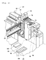
- working heads 56 and 58 include eight rod-shaped mounting units 80. These eight mounting units 80 are held in a state where the axial direction is perpendicular at an equal angular pitch at the outer circumferential portion of unit holding body 82, and suction nozzle 88 is mounted at the tip portion of each of mounting units 80. Then, suction nozzle 88 mounted at the tip portion mounting unit 80 extends downward from the lower surface of unit holding body 82.
- working heads 56 and 58 in a state where the cover is removed are illustrated.
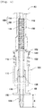
- each mounting unit 80 generally includes tubular unit main body 100, coupling pipe 102 that extends downward from the lower end of unit main body 100, and holder 104 that holds coupling pipe 102 therein.
- through hole 106 that penetrates in the up-down direction is formed, through hole 106 is divided by large-diameter section 108 positioned below, and small-diameter section 110 continuous upward from large-diameter section 108, and step surface 112 is formed between large-diameter section 108 and small-diameter section 110.
- the inner diameter of large-diameter section 108 of through hole 106 is slightly greater than the outer diameter of coupling pipe 102, and the upper end portion of coupling pipe 102 is inserted into large-diameter section 108 of through hole 106. Further, between step surface 112 of through hole 106 and the upper end face of coupling pipe 102, coil spring 114 is disposed in a state of being compressed. Accordingly, coupling pipe 102 is biased toward the direction extending from large-diameter section 108 of through hole 106.
- Holder 104 includes inner tube 116 and outer tube 118.
- the lower end portion of unit main body 100 is fixed to the upper end portion of inner tube 116, and the upper end portion of outer tube 118 is externally fitted to the lower end portion of inner tube 116.
- the inside of holder 104 that is, the inside of inner tube 116 and outer tube 118, coupling pipe 102 that extends from large-diameter section 108 of unit main body 100 is held. Accordingly, in a state where coupling pipe 102 is held on the inside, holder 104 can extend and contract.
- flange section 120 that protrudes outward is formed at the upper end portion of inner tube 116, and coil spring 122 is disposed in a compressed state between flange section 120 and the upper end portion of outer tube 118. Accordingly, outer tube 118 of holder 104 for holding coupling pipe 102 is biased downward.
- suction nozzle 88 is mounted on the lower end portion of holder 104, that is, the lower end portion of outer tube 118. Then, coupling pipe 102 held inside holder 104 makes the inside of suction nozzle 88 and through hole 106 of unit main body 100 communicate with each other, and accordingly, suction nozzle 88 picks up and holds electronic components by suctioning air from through hole 106.
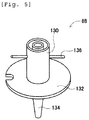
- suction nozzle 88 includes body cylinder 130, flange section 132, suction pipe 134, and locking pin 136.
- Body cylinder 130 has a cylindrical shape, and flange section 132 protrudes outward from the lower end portion of body cylinder 130.
- Suction pipe 134 has a thin pipe shape and is held by body cylinder 130 to be slidable in the axial line direction in a state of extending downwards from the lower end portion of body cylinder 130.
- Locking pin 136 is provided at the upper end portion of body cylinder 130 so as to extend in the radial direction of body cylinder 130, and suction nozzle 88 is detachably attached to the lower end portion of holder 104, that is, the lower end portion of outer tube 118, using locking pin 136.
- the extension amount of suction pipe 134 from the lower end portion of body cylinder 130 is regulated to X1 by a stopper (not illustrated).
- a stopper not illustrated.
- suction pipe 134 has extension amount X2 ( ⁇ X1) and suction nozzle 88 contracts, as the negative pressure air is supplied to through hole 106, suction nozzle 88 picks up and holds the electronic component. Further, in a state where suction nozzle 88 extends and contracts, as the positive pressure air is supplied to through hole 106, the held electronic component is disengaged.
- unit holding body 82 that holds eight mounting units 80 intermittently rotates for each installation angle of mounting unit 80 by electromagnetic motor (refer to Fig. 8 ) 152 of holding body rotating device 150. Accordingly, mounting unit 80 is sequentially stopped at the lifting and lowering station which is one stopping position among the stopping positions of multiple mounting units 80. Mounting unit 80 positioned at the lifting and lowering station is lifted and lowered by electromagnetic motor (refer to Fig. 8 ) 158 of unit lifting and lowering device 156. Accordingly, the position in the up-down direction of the component picked up and held by suction nozzle 88 is changed.
- a stopping position different from the lifting and lowering station is a revolving station
- mounting unit 80 positioned at the station rotates by electromagnetic motor (refer to Fig. 8 ) 162 of revolving device 160. Accordingly, the holding orientation of the component picked up and held by suction nozzle 88 is changed.
- side camera 26 is attached to the lower end of sliders 74 and 76 in a state of facing the side, and the tip end of one mounting unit 80 among multiple mounting units 80 of working heads 56 and 58 mounted on sliders 74 and 76, that is, suction nozzle 88, is imaged. Accordingly, side camera 26 images the components held by suction nozzle 88 of working heads 56 and 58 from the side.
- part camera 28 is disposed between substrate conveyance and holding device 22 and component supply device 30 on frame section 40 in a state of facing upward. Accordingly, part camera 28 images the components held by suction nozzle 88 of working heads 56 and 58 from the below.
- nozzle station 29 includes nozzle tray 166 that accommodates multiple suction nozzles 88.
- suction nozzle 88 attached to mounting unit 80 of working heads 56 and 58 and suction nozzle 88 accommodated in nozzle tray 166 are automatically exchanged, if necessary.
- component supply device 30 is disposed at one end portion of frame section 40 in the front-rear direction.
- Component supply device 30 includes tray-type component supply device 170 and feeder-type component supply device (refer to Fig. 8 ) 172.
- Tray-type component supply device 170 is a device for supplying components which is in a state of being placed on a tray.
- Feeder-type component supply device 172 is a device for supplying components by a tape feeder or a stick feeder (not illustrated).
- Bulk component supply device 32 is disposed at the other end portion of frame section 40 in the front-rear direction.
- Bulk component supply device 32 is a device for aligning scattered multiple components and supplying the components in an aligned state.
- bulk component supply device 32 is a device for aligning multiple components in any orientation to a predetermined orientation, and supplying the components in a predetermined orientation.
- control device 36 includes controller 180, multiple drive circuits 182, and image processing device 186.
- Multiple drive circuits 182 are connected to conveyance device 50, clamping device 52, electromagnetic motors 66, 68, 70, 72, 152, 158, and 162, positive and negative pressure supply device 140, tray-type component supply device 170, feeder-type component supply device 172, and bulk component supply device 32 which are described above.
- Controller 180 includes a CPU, a ROM, a RAM, and the like, is mainly a computer, and is connected to multiple drive circuits 182. Accordingly, the operations of substrate conveyance and holding device 22, component mounting device 24, and the like are controlled by controller 180.
- Controller 180 is also connected to image processing device 186.
- Image processing device 186 is for processing image data obtained by side camera 26 and part camera 28, and controller 180 acquires various types of information from the image data.
- circuit substrate 12 held by substrate conveyance and holding device 22.
- circuit substrate 12 is conveyed to a work position and held at that position in a fixed manner by clamping device 52.
- component supply device 30 or bulk component supply device 32 supplies electronic components at a predetermined supply position. Then, any one of working heads 56 and 58 is moved above the supply position of the component, mounting unit 80 positioned at the lifting and lowering station of working heads 56 and 58 is lowered, and accordingly, the electronic component is picked up and held by suction nozzle 88 of mounting unit 80.
- working heads 56 and 58 move above part camera 28, and the electronic component held by suction nozzle 88 is imaged by part camera 28. Further, in working heads 56 and 58 that hold the electronic component, the electronic component held by suction nozzle 88 is imaged by side camera 26. Then, based on the captured image data of side camera 26 and part camera 28, controller 180 calculates the holding orientation or the like of the electronic component held by suction nozzle 88. Subsequently, working heads 56 and 58 that hold the electronic components move above circuit substrate 12 and mount the components which are being held on circuit substrate 12 after correcting errors or the like in the holding orientation of the components.
- jig base 190 is disposed between substrate conveyance and holding device 22 and bulk component supply device 32. This may be between substrate conveyance and holding device 22 and component supply device 30.
- Jig base 190 is a base for temporarily mounting the electronic components, and simulation of mounting work of the electronic components is performed with respect to jig base 190. Accordingly, the mounting work of the appropriate electronic components to circuit substrate 12 is ensured.
- component mounting machine 10 has a structure in which the load on the electronic component at the time of mounting work is reduced and suction nozzle 88 can extend and contract. Specifically, as illustrated in Fig. 4 , in a state where suction nozzle 88 extends the most, suction pipe 134 has extension amount X1, and suction pipe 134 is biased downward together with coupling pipe 102 due to elastic force of coil spring 114. Then, for example, when the electronic component is picked up and held by suction nozzle 88, and when the electronic component is in contact with the tip end of suction pipe 134, as illustrated in Fig. 6 , suction pipe 134 slides to the inside of body cylinder 130 against the elastic force of coil spring 114.
- suction nozzle 88 has a structure that can extend and contract, the load on the electronic component during the mounting work is reduced.
- the slidability of suction pipe 134 deteriorates due to degradation, adhesion of dirt, or the like.
- suction pipe 134 is unlikely to slide toward the inside of body cylinder 130, and there is a concern that the load on the electronic component increases. Therefore, in mounting unit 80, when the slidability of suction pipe 134 deteriorates, holder 104 that holds suction nozzle 88 contracts, and the load on the electronic component is reduced.
- circuit substrate 12 which is at an interval between the mounting works, is conveyed to the work position and held fixedly by clamping device 52, working heads 56 and 58 are moved above jig base 190, and mounting unit 80 is lowered toward jig base 190.
- suction nozzle 88 is mounted on mounting unit 80, and suction nozzle 88 is in a state of not holding anything.
- the driving source for lowering mounting unit 80 that is, the operation of electromagnetic motor 158 of unit lifting and lowering device 156 is controlled, but when mounting unit 80 is lowered, the operation of electromagnetic motor 158 is controlled such that the tip end of suction nozzle 88, that is, the tip end of suction pipe 134, comes into contact with the surface of jig base 190 and is slightly pressed.
- the operation of electromagnetic motor 158 is controlled such that the tip end of suction pipe 134 is positioned slightly below the Z-axis coordinate of the surface of jig base 190, specifically, for example, a few mm below.
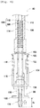
- mounting unit 80 stops being lowered and is maintained at this position. At this time, in mounting unit 80, as illustrated in Fig. 6 , suction nozzle 88 contracts, and suction pipe 134 is maintained in a state of sliding toward the inside of body cylinder 130 against the elastic force of coil spring 114. Therefore, electromagnetic motor 158 exerts a motor force against the elastic force of coil spring 114; however, since the elastic force of coil spring 114 is small, the torque value of electromagnetic motor 158 hardly changes.
- mounting unit 80 stops being lowered and is maintained at this position. At this time, in mounting unit 80, as illustrated in Fig. 7 , holder 104 contracts, and outer tube 118 is maintained in a state of being moved upward against the elastic force of coil spring 122. Furthermore, coupling pipe 102 also moves upward together with outer tube 118 and is maintained in a state of being moved upward against the elastic force of coil spring 114. Therefore, electromagnetic motor 158 exerts a motor force that is against not only the elastic force of coil spring 114 but also the elastic force of coil spring 122, and the torque value of electromagnetic motor 158 greatly changes.
- the slidability of suction pipe 134 of suction nozzle 88 is confirmed by using the existing equipment.
- jig base 190 and unit lifting and lowering device 156 are existing equipment, and the slidability of suction pipe 134 of suction nozzle 88 can be confirmed only by controlling the operation of unit lifting and lowering device 156 such that the tip end of suction nozzle 88 comes into contact with the surface of jig base 190, and by monitoring the torque value of electromagnetic motor 158 at this time.
- suction pipe 134 of suction nozzle 88 can be confirmed only by lifting and lowering mounting unit 80, it is possible to perform the inspection of suction nozzle 88 by using a short period of time such as an interval between the mounting works.
- suction nozzles 88 mounted on all mounting units 80 of working heads 56 and 58 can be individually inspected, it is possible to individually manage each of multiple suction nozzles 88.
- suction pipe 134 As suction pipe 134 is pressed against jig base 190, suction pipe 134 slides toward the inside of body cylinder 130, and in this state, that is, in a state where suction pipe 134 enters the inside of body cylinder 130, there is a case where body cylinder 130 and suction pipe 134 are fixed.
- suction pipe 134 slides smoothly; however, a foreign matter enters the back of body cylinder 130, and suction pipe 134 enters the inside of body cylinder 130 by a predetermined amount, and accordingly, there is a case where the foreign matter comes into contact with suction pipe 134.
- body cylinder 130 and suction pipe 134 are fixed.
- suction nozzle 88 in a state where suction nozzle 88 contracts, when there is no problem in the slidability of suction pipe 134, suction nozzle 88 extends by the elastic amount of coil spring 114; however, there is a case where suction nozzle 88 does not extend due to the foreign matter that entered between body cylinder 130 and suction pipe 134. In such a case, there is no problem in the slidability of suction pipe 134 when suction nozzle 88 contracts, and accordingly, the deterioration of the slidability of suction pipe 134 cannot be confirmed by the inspection by the above-described method.
- suction pipe 134 is confirmed based on the tip end position of suction pipe 134 before suction pipe 134 is pressed against jig base 190 and the tip end position of suction pipe 134 after suction pipe 134 is pressed against jig base 190. Specifically, before suction pipe 134 is pressed against jig base 190, suction nozzle 88 is imaged by side camera 26. Then, the extension amount of suction pipe 134 from body cylinder 130, that is, the extension amount of suction pipe 134 before the pressing work is calculated based on the captured image data.
- suction pipe 134 that entered the inside of body cylinder 130 is in a state of remaining inside body cylinder 130, and it is determined that an abnormality occurred in suction nozzle 88.
- the difference between the extension amount of suction pipe 134 before the pressing work and the extension amount of suction pipe 134 after the pressing work is equal to or less than the set amount, it is determined that the slidability of suction pipe 134 is excellent.
- suction pipe 134 that entered the inside of body cylinder 130 is restored by the elastic force of coil spring 114, and it is determined that suction nozzle 88 is normal.
- suction nozzle 88 determined that the slidability of suction pipe 134 deteriorates is removed from mounting unit 80, and is accommodated in nozzle tray 166, and suction nozzle 88 accommodated in nozzle tray 166 is mounted in mounting unit 80. Accordingly, while reducing the load on the electronic components, appropriate mounting work is ensured. When there is no suction nozzle 88 that can be exchanged, it is notified that suction nozzle 88 should be replenished or exchanged.
- component mounting machine 10 is an example of a mounting work machine.
- Side camera 26 is an example of an imaging device.
- Control device 36 is an example of a confirmation device.
- Suction nozzle 88 is an example of a suction nozzle.
- Suction pipe 134 is an example of a nozzle tube.
- Unit lifting and lowering device 156 is an example of a lifting and lowering device.
- Electromagnetic motor 158 is an example of an electromagnetic motor.
- Jig base 190 is an example of a set part.
- suction pipe 134 when the slidability of suction pipe 134 is confirmed, suction pipe 134 is pressed against jig base 190; however, suction pipe 134 may be pressed against any location as long as a predetermined hardness is provided and the positional coordinates can be specified.
Landscapes
- Engineering & Computer Science (AREA)
- Manufacturing & Machinery (AREA)
- Microelectronics & Electronic Packaging (AREA)
- Operations Research (AREA)
- Supply And Installment Of Electrical Components (AREA)
Applications Claiming Priority (1)
| Application Number | Priority Date | Filing Date | Title |
|---|---|---|---|
| PCT/JP2018/015847 WO2019202655A1 (ja) | 2018-04-17 | 2018-04-17 | 装着作業機、および確認方法 |
Publications (2)
| Publication Number | Publication Date |
|---|---|
| EP3784014A1 true EP3784014A1 (de) | 2021-02-24 |
| EP3784014A4 EP3784014A4 (de) | 2021-04-21 |
Family
ID=68238816
Family Applications (1)
| Application Number | Title | Priority Date | Filing Date |
|---|---|---|---|
| EP18915545.0A Pending EP3784014A4 (de) | 2018-04-17 | 2018-04-17 | Montageoperationsmaschine und bestätigungsverfahren |
Country Status (3)
| Country | Link |
|---|---|
| EP (1) | EP3784014A4 (de) |
| JP (1) | JP6950085B2 (de) |
| WO (1) | WO2019202655A1 (de) |
Families Citing this family (3)
| Publication number | Priority date | Publication date | Assignee | Title |
|---|---|---|---|---|
| JP7313551B2 (ja) * | 2020-04-28 | 2023-07-24 | 株式会社Fuji | 部品実装機 |
| JP7584030B2 (ja) * | 2020-12-09 | 2024-11-15 | パナソニックIpマネジメント株式会社 | 状態検出装置、実装システム、状態検出方法、及び、プログラム |
| WO2023026556A1 (ja) | 2021-08-26 | 2023-03-02 | パナソニックIpマネジメント株式会社 | 部品装着装置、および判定方法 |
Family Cites Families (11)
| Publication number | Priority date | Publication date | Assignee | Title |
|---|---|---|---|---|
| JP4360257B2 (ja) * | 2004-04-15 | 2009-11-11 | パナソニック株式会社 | 電子部品実装用装置および電子部品実装用装置における状態判定方法 |
| JP2006108384A (ja) | 2004-10-05 | 2006-04-20 | Juki Corp | 実装装置、その実装荷重補正方法及びノズル検査方法 |
| JP4455260B2 (ja) * | 2004-10-12 | 2010-04-21 | ヤマハ発動機株式会社 | 部品搬送装置、表面実装機および部品試験装置 |
| JP4842085B2 (ja) * | 2006-10-19 | 2011-12-21 | Juki株式会社 | 部品実装装置 |
| JP5774971B2 (ja) * | 2011-11-25 | 2015-09-09 | ヤマハ発動機株式会社 | 表面実装装置およびヘッド駆動制御方法 |
| JP6021550B2 (ja) * | 2012-09-26 | 2016-11-09 | Juki株式会社 | 電子部品実装装置 |
| JP6302052B2 (ja) | 2014-04-22 | 2018-03-28 | 富士機械製造株式会社 | 荷重測定方法および、回収方法 |
| CN107114011B (zh) * | 2015-01-19 | 2020-04-14 | 株式会社富士 | 元件安装装置用头单元 |
| JP6424097B2 (ja) * | 2015-01-20 | 2018-11-14 | ヤマハ発動機株式会社 | ノズル検査装置、ノズル検査方法および部品搬送装置 |
| JP6486501B2 (ja) * | 2015-12-03 | 2019-03-20 | ヤマハ発動機株式会社 | 部品実装装置 |
| JP6552423B2 (ja) * | 2016-01-20 | 2019-07-31 | ヤマハ発動機株式会社 | ノズル給油装置および表面実装機 |
-
2018
- 2018-04-17 WO PCT/JP2018/015847 patent/WO2019202655A1/ja not_active Ceased
- 2018-04-17 EP EP18915545.0A patent/EP3784014A4/de active Pending
- 2018-04-17 JP JP2020514821A patent/JP6950085B2/ja active Active
Also Published As
| Publication number | Publication date |
|---|---|
| EP3784014A4 (de) | 2021-04-21 |
| JPWO2019202655A1 (ja) | 2020-12-03 |
| JP6950085B2 (ja) | 2021-10-13 |
| WO2019202655A1 (ja) | 2019-10-24 |
Similar Documents
| Publication | Publication Date | Title |
|---|---|---|
| JP4952692B2 (ja) | 電子部品実装装置および電子部品実装方法 | |
| KR20120080537A (ko) | 부품 실장 시스템 및 부품 실장 방법 | |
| CN202799576U (zh) | 安装部件检查装置 | |
| EP3032933A1 (de) | Elektronische bauteilbestückungseinrichtung und übertragungsbestätigungsverfahren | |
| CN101690444B (zh) | 元件吸附方法及表面安装机 | |
| EP3784014A1 (de) | Montageoperationsmaschine und bestätigungsverfahren | |
| US11185001B2 (en) | Component placing device | |
| JP2016134531A (ja) | ノズル検査装置、ノズル検査方法および部品搬送装置 | |
| JP2009016673A (ja) | 部品の吸着位置補正方法および部品移載装置 | |
| JP4350537B2 (ja) | 部品挿着装置、表面実装機および部品試験装置 | |
| JP6967696B2 (ja) | 部品搭載装置および部品搭載方法 | |
| JP2001196799A (ja) | 基板支持状態検査方法 | |
| JP6886981B2 (ja) | 部品実装機 | |
| JP7431927B2 (ja) | 部品実装システム | |
| CN112470556B (zh) | 信息处理装置、作业系统及决定方法 | |
| JP7195914B2 (ja) | 部品実装システム | |
| JP7213411B2 (ja) | 部品搭載装置 | |
| JP7223928B2 (ja) | 部品搭載装置 | |
| JP7418142B2 (ja) | 対基板作業機、および異物検出方法 | |
| KR102755690B1 (ko) | 부품 이송 장치 | |
| JP2019061992A (ja) | 部品搭載装置 | |
| JP6967695B2 (ja) | 部品搭載装置および部品搭載方法 | |
| EP3986106B1 (de) | Komponentenmontierer | |
| JP2003152397A (ja) | 電気部品装着システムおよび電気回路製造方法 | |
| JP2026010899A (ja) | 部品実装装置および部品実装方法 |
Legal Events
| Date | Code | Title | Description |
|---|---|---|---|
| STAA | Information on the status of an ep patent application or granted ep patent |
Free format text: STATUS: THE INTERNATIONAL PUBLICATION HAS BEEN MADE |
|
| PUAI | Public reference made under article 153(3) epc to a published international application that has entered the european phase |
Free format text: ORIGINAL CODE: 0009012 |
|
| STAA | Information on the status of an ep patent application or granted ep patent |
Free format text: STATUS: REQUEST FOR EXAMINATION WAS MADE |
|
| 17P | Request for examination filed |
Effective date: 20200902 |
|
| AK | Designated contracting states |
Kind code of ref document: A1 Designated state(s): AL AT BE BG CH CY CZ DE DK EE ES FI FR GB GR HR HU IE IS IT LI LT LU LV MC MK MT NL NO PL PT RO RS SE SI SK SM TR |
|
| AX | Request for extension of the european patent |
Extension state: BA ME |
|
| A4 | Supplementary search report drawn up and despatched |
Effective date: 20210324 |
|
| RIC1 | Information provided on ipc code assigned before grant |
Ipc: H05K 13/04 20060101AFI20210318BHEP Ipc: H05K 13/08 20060101ALI20210318BHEP |
|
| DAV | Request for validation of the european patent (deleted) | ||
| DAX | Request for extension of the european patent (deleted) | ||
| STAA | Information on the status of an ep patent application or granted ep patent |
Free format text: STATUS: EXAMINATION IS IN PROGRESS |
|
| 17Q | First examination report despatched |
Effective date: 20230217 |
|
| P01 | Opt-out of the competence of the unified patent court (upc) registered |
Effective date: 20230328 |
|
| GRAP | Despatch of communication of intention to grant a patent |
Free format text: ORIGINAL CODE: EPIDOSNIGR1 |
|
| STAA | Information on the status of an ep patent application or granted ep patent |
Free format text: STATUS: GRANT OF PATENT IS INTENDED |