EP3784148B1 - Implants - Google Patents
Implants Download PDFInfo
- Publication number
- EP3784148B1 EP3784148B1 EP19834470.7A EP19834470A EP3784148B1 EP 3784148 B1 EP3784148 B1 EP 3784148B1 EP 19834470 A EP19834470 A EP 19834470A EP 3784148 B1 EP3784148 B1 EP 3784148B1
- Authority
- EP
- European Patent Office
- Prior art keywords
- insert
- implant
- top surface
- extending
- lateral
- Prior art date
- Legal status (The legal status is an assumption and is not a legal conclusion. Google has not performed a legal analysis and makes no representation as to the accuracy of the status listed.)
- Active
Links
Images


























Classifications
-
- A—HUMAN NECESSITIES
- A61—MEDICAL OR VETERINARY SCIENCE; HYGIENE
- A61F—FILTERS IMPLANTABLE INTO BLOOD VESSELS; PROSTHESES; DEVICES PROVIDING PATENCY TO, OR PREVENTING COLLAPSING OF, TUBULAR STRUCTURES OF THE BODY, e.g. STENTS; ORTHOPAEDIC, NURSING OR CONTRACEPTIVE DEVICES; FOMENTATION; TREATMENT OR PROTECTION OF EYES OR EARS; BANDAGES, DRESSINGS OR ABSORBENT PADS; FIRST-AID KITS
- A61F2/00—Filters implantable into blood vessels; Prostheses, i.e. artificial substitutes or replacements for parts of the body; Appliances for connecting them with the body; Devices providing patency to, or preventing collapsing of, tubular structures of the body, e.g. stents
- A61F2/02—Prostheses implantable into the body
- A61F2/30—Joints
- A61F2/42—Joints for wrists or ankles; for hands, e.g. fingers; for feet, e.g. toes
- A61F2/4202—Joints for wrists or ankles; for hands, e.g. fingers; for feet, e.g. toes for ankles
-
- A—HUMAN NECESSITIES
- A61—MEDICAL OR VETERINARY SCIENCE; HYGIENE
- A61F—FILTERS IMPLANTABLE INTO BLOOD VESSELS; PROSTHESES; DEVICES PROVIDING PATENCY TO, OR PREVENTING COLLAPSING OF, TUBULAR STRUCTURES OF THE BODY, e.g. STENTS; ORTHOPAEDIC, NURSING OR CONTRACEPTIVE DEVICES; FOMENTATION; TREATMENT OR PROTECTION OF EYES OR EARS; BANDAGES, DRESSINGS OR ABSORBENT PADS; FIRST-AID KITS
- A61F2/00—Filters implantable into blood vessels; Prostheses, i.e. artificial substitutes or replacements for parts of the body; Appliances for connecting them with the body; Devices providing patency to, or preventing collapsing of, tubular structures of the body, e.g. stents
- A61F2/02—Prostheses implantable into the body
- A61F2/30—Joints
- A61F2/42—Joints for wrists or ankles; for hands, e.g. fingers; for feet, e.g. toes
-
- A—HUMAN NECESSITIES
- A61—MEDICAL OR VETERINARY SCIENCE; HYGIENE
- A61F—FILTERS IMPLANTABLE INTO BLOOD VESSELS; PROSTHESES; DEVICES PROVIDING PATENCY TO, OR PREVENTING COLLAPSING OF, TUBULAR STRUCTURES OF THE BODY, e.g. STENTS; ORTHOPAEDIC, NURSING OR CONTRACEPTIVE DEVICES; FOMENTATION; TREATMENT OR PROTECTION OF EYES OR EARS; BANDAGES, DRESSINGS OR ABSORBENT PADS; FIRST-AID KITS
- A61F2/00—Filters implantable into blood vessels; Prostheses, i.e. artificial substitutes or replacements for parts of the body; Appliances for connecting them with the body; Devices providing patency to, or preventing collapsing of, tubular structures of the body, e.g. stents
- A61F2/02—Prostheses implantable into the body
- A61F2/30—Joints
- A61F2002/30001—Additional features of subject-matter classified in A61F2/28, A61F2/30 and subgroups thereof
- A61F2002/30108—Shapes
- A61F2002/3011—Cross-sections or two-dimensional shapes
- A61F2002/30112—Rounded shapes, e.g. with rounded corners
-
- A—HUMAN NECESSITIES
- A61—MEDICAL OR VETERINARY SCIENCE; HYGIENE
- A61F—FILTERS IMPLANTABLE INTO BLOOD VESSELS; PROSTHESES; DEVICES PROVIDING PATENCY TO, OR PREVENTING COLLAPSING OF, TUBULAR STRUCTURES OF THE BODY, e.g. STENTS; ORTHOPAEDIC, NURSING OR CONTRACEPTIVE DEVICES; FOMENTATION; TREATMENT OR PROTECTION OF EYES OR EARS; BANDAGES, DRESSINGS OR ABSORBENT PADS; FIRST-AID KITS
- A61F2/00—Filters implantable into blood vessels; Prostheses, i.e. artificial substitutes or replacements for parts of the body; Appliances for connecting them with the body; Devices providing patency to, or preventing collapsing of, tubular structures of the body, e.g. stents
- A61F2/02—Prostheses implantable into the body
- A61F2/30—Joints
- A61F2002/30001—Additional features of subject-matter classified in A61F2/28, A61F2/30 and subgroups thereof
- A61F2002/30108—Shapes
- A61F2002/3011—Cross-sections or two-dimensional shapes
- A61F2002/30159—Concave polygonal shapes
- A61F2002/30164—Concave polygonal shapes dovetail-shaped
-
- A—HUMAN NECESSITIES
- A61—MEDICAL OR VETERINARY SCIENCE; HYGIENE
- A61F—FILTERS IMPLANTABLE INTO BLOOD VESSELS; PROSTHESES; DEVICES PROVIDING PATENCY TO, OR PREVENTING COLLAPSING OF, TUBULAR STRUCTURES OF THE BODY, e.g. STENTS; ORTHOPAEDIC, NURSING OR CONTRACEPTIVE DEVICES; FOMENTATION; TREATMENT OR PROTECTION OF EYES OR EARS; BANDAGES, DRESSINGS OR ABSORBENT PADS; FIRST-AID KITS
- A61F2/00—Filters implantable into blood vessels; Prostheses, i.e. artificial substitutes or replacements for parts of the body; Appliances for connecting them with the body; Devices providing patency to, or preventing collapsing of, tubular structures of the body, e.g. stents
- A61F2/02—Prostheses implantable into the body
- A61F2/30—Joints
- A61F2002/30001—Additional features of subject-matter classified in A61F2/28, A61F2/30 and subgroups thereof
- A61F2002/30108—Shapes
- A61F2002/30199—Three-dimensional shapes
-
- A—HUMAN NECESSITIES
- A61—MEDICAL OR VETERINARY SCIENCE; HYGIENE
- A61F—FILTERS IMPLANTABLE INTO BLOOD VESSELS; PROSTHESES; DEVICES PROVIDING PATENCY TO, OR PREVENTING COLLAPSING OF, TUBULAR STRUCTURES OF THE BODY, e.g. STENTS; ORTHOPAEDIC, NURSING OR CONTRACEPTIVE DEVICES; FOMENTATION; TREATMENT OR PROTECTION OF EYES OR EARS; BANDAGES, DRESSINGS OR ABSORBENT PADS; FIRST-AID KITS
- A61F2/00—Filters implantable into blood vessels; Prostheses, i.e. artificial substitutes or replacements for parts of the body; Appliances for connecting them with the body; Devices providing patency to, or preventing collapsing of, tubular structures of the body, e.g. stents
- A61F2/02—Prostheses implantable into the body
- A61F2/30—Joints
- A61F2002/30001—Additional features of subject-matter classified in A61F2/28, A61F2/30 and subgroups thereof
- A61F2002/30316—The prosthesis having different structural features at different locations within the same prosthesis; Connections between prosthetic parts; Special structural features of bone or joint prostheses not otherwise provided for
- A61F2002/30317—The prosthesis having different structural features at different locations within the same prosthesis
-
- A—HUMAN NECESSITIES
- A61—MEDICAL OR VETERINARY SCIENCE; HYGIENE
- A61F—FILTERS IMPLANTABLE INTO BLOOD VESSELS; PROSTHESES; DEVICES PROVIDING PATENCY TO, OR PREVENTING COLLAPSING OF, TUBULAR STRUCTURES OF THE BODY, e.g. STENTS; ORTHOPAEDIC, NURSING OR CONTRACEPTIVE DEVICES; FOMENTATION; TREATMENT OR PROTECTION OF EYES OR EARS; BANDAGES, DRESSINGS OR ABSORBENT PADS; FIRST-AID KITS
- A61F2/00—Filters implantable into blood vessels; Prostheses, i.e. artificial substitutes or replacements for parts of the body; Appliances for connecting them with the body; Devices providing patency to, or preventing collapsing of, tubular structures of the body, e.g. stents
- A61F2/02—Prostheses implantable into the body
- A61F2/30—Joints
- A61F2002/30001—Additional features of subject-matter classified in A61F2/28, A61F2/30 and subgroups thereof
- A61F2002/30316—The prosthesis having different structural features at different locations within the same prosthesis; Connections between prosthetic parts; Special structural features of bone or joint prostheses not otherwise provided for
- A61F2002/30317—The prosthesis having different structural features at different locations within the same prosthesis
- A61F2002/30327—The prosthesis having different structural features at different locations within the same prosthesis differing in diameter
-
- A—HUMAN NECESSITIES
- A61—MEDICAL OR VETERINARY SCIENCE; HYGIENE
- A61F—FILTERS IMPLANTABLE INTO BLOOD VESSELS; PROSTHESES; DEVICES PROVIDING PATENCY TO, OR PREVENTING COLLAPSING OF, TUBULAR STRUCTURES OF THE BODY, e.g. STENTS; ORTHOPAEDIC, NURSING OR CONTRACEPTIVE DEVICES; FOMENTATION; TREATMENT OR PROTECTION OF EYES OR EARS; BANDAGES, DRESSINGS OR ABSORBENT PADS; FIRST-AID KITS
- A61F2/00—Filters implantable into blood vessels; Prostheses, i.e. artificial substitutes or replacements for parts of the body; Appliances for connecting them with the body; Devices providing patency to, or preventing collapsing of, tubular structures of the body, e.g. stents
- A61F2/02—Prostheses implantable into the body
- A61F2/30—Joints
- A61F2002/30001—Additional features of subject-matter classified in A61F2/28, A61F2/30 and subgroups thereof
- A61F2002/30316—The prosthesis having different structural features at different locations within the same prosthesis; Connections between prosthetic parts; Special structural features of bone or joint prostheses not otherwise provided for
- A61F2002/30329—Connections or couplings between prosthetic parts, e.g. between modular parts; Connecting elements
- A61F2002/30383—Connections or couplings between prosthetic parts, e.g. between modular parts; Connecting elements made by laterally inserting a protrusion, e.g. a rib into a complementarily-shaped groove
-
- A—HUMAN NECESSITIES
- A61—MEDICAL OR VETERINARY SCIENCE; HYGIENE
- A61F—FILTERS IMPLANTABLE INTO BLOOD VESSELS; PROSTHESES; DEVICES PROVIDING PATENCY TO, OR PREVENTING COLLAPSING OF, TUBULAR STRUCTURES OF THE BODY, e.g. STENTS; ORTHOPAEDIC, NURSING OR CONTRACEPTIVE DEVICES; FOMENTATION; TREATMENT OR PROTECTION OF EYES OR EARS; BANDAGES, DRESSINGS OR ABSORBENT PADS; FIRST-AID KITS
- A61F2/00—Filters implantable into blood vessels; Prostheses, i.e. artificial substitutes or replacements for parts of the body; Appliances for connecting them with the body; Devices providing patency to, or preventing collapsing of, tubular structures of the body, e.g. stents
- A61F2/02—Prostheses implantable into the body
- A61F2/30—Joints
- A61F2002/30001—Additional features of subject-matter classified in A61F2/28, A61F2/30 and subgroups thereof
- A61F2002/30316—The prosthesis having different structural features at different locations within the same prosthesis; Connections between prosthetic parts; Special structural features of bone or joint prostheses not otherwise provided for
- A61F2002/30329—Connections or couplings between prosthetic parts, e.g. between modular parts; Connecting elements
- A61F2002/30383—Connections or couplings between prosthetic parts, e.g. between modular parts; Connecting elements made by laterally inserting a protrusion, e.g. a rib into a complementarily-shaped groove
- A61F2002/30387—Dovetail connection
-
- A—HUMAN NECESSITIES
- A61—MEDICAL OR VETERINARY SCIENCE; HYGIENE
- A61F—FILTERS IMPLANTABLE INTO BLOOD VESSELS; PROSTHESES; DEVICES PROVIDING PATENCY TO, OR PREVENTING COLLAPSING OF, TUBULAR STRUCTURES OF THE BODY, e.g. STENTS; ORTHOPAEDIC, NURSING OR CONTRACEPTIVE DEVICES; FOMENTATION; TREATMENT OR PROTECTION OF EYES OR EARS; BANDAGES, DRESSINGS OR ABSORBENT PADS; FIRST-AID KITS
- A61F2/00—Filters implantable into blood vessels; Prostheses, i.e. artificial substitutes or replacements for parts of the body; Appliances for connecting them with the body; Devices providing patency to, or preventing collapsing of, tubular structures of the body, e.g. stents
- A61F2/02—Prostheses implantable into the body
- A61F2/30—Joints
- A61F2002/30001—Additional features of subject-matter classified in A61F2/28, A61F2/30 and subgroups thereof
- A61F2002/30316—The prosthesis having different structural features at different locations within the same prosthesis; Connections between prosthetic parts; Special structural features of bone or joint prostheses not otherwise provided for
- A61F2002/30329—Connections or couplings between prosthetic parts, e.g. between modular parts; Connecting elements
- A61F2002/30383—Connections or couplings between prosthetic parts, e.g. between modular parts; Connecting elements made by laterally inserting a protrusion, e.g. a rib into a complementarily-shaped groove
- A61F2002/3039—Connections or couplings between prosthetic parts, e.g. between modular parts; Connecting elements made by laterally inserting a protrusion, e.g. a rib into a complementarily-shaped groove with possibility of relative movement of the rib within the groove
- A61F2002/30398—Sliding
- A61F2002/30401—Sliding with additional means for preventing or locking said sliding
-
- A—HUMAN NECESSITIES
- A61—MEDICAL OR VETERINARY SCIENCE; HYGIENE
- A61F—FILTERS IMPLANTABLE INTO BLOOD VESSELS; PROSTHESES; DEVICES PROVIDING PATENCY TO, OR PREVENTING COLLAPSING OF, TUBULAR STRUCTURES OF THE BODY, e.g. STENTS; ORTHOPAEDIC, NURSING OR CONTRACEPTIVE DEVICES; FOMENTATION; TREATMENT OR PROTECTION OF EYES OR EARS; BANDAGES, DRESSINGS OR ABSORBENT PADS; FIRST-AID KITS
- A61F2/00—Filters implantable into blood vessels; Prostheses, i.e. artificial substitutes or replacements for parts of the body; Appliances for connecting them with the body; Devices providing patency to, or preventing collapsing of, tubular structures of the body, e.g. stents
- A61F2/02—Prostheses implantable into the body
- A61F2/30—Joints
- A61F2002/30001—Additional features of subject-matter classified in A61F2/28, A61F2/30 and subgroups thereof
- A61F2002/30316—The prosthesis having different structural features at different locations within the same prosthesis; Connections between prosthetic parts; Special structural features of bone or joint prostheses not otherwise provided for
- A61F2002/30329—Connections or couplings between prosthetic parts, e.g. between modular parts; Connecting elements
- A61F2002/30476—Connections or couplings between prosthetic parts, e.g. between modular parts; Connecting elements locked by an additional locking mechanism
- A61F2002/305—Snap connection
-
- A—HUMAN NECESSITIES
- A61—MEDICAL OR VETERINARY SCIENCE; HYGIENE
- A61F—FILTERS IMPLANTABLE INTO BLOOD VESSELS; PROSTHESES; DEVICES PROVIDING PATENCY TO, OR PREVENTING COLLAPSING OF, TUBULAR STRUCTURES OF THE BODY, e.g. STENTS; ORTHOPAEDIC, NURSING OR CONTRACEPTIVE DEVICES; FOMENTATION; TREATMENT OR PROTECTION OF EYES OR EARS; BANDAGES, DRESSINGS OR ABSORBENT PADS; FIRST-AID KITS
- A61F2/00—Filters implantable into blood vessels; Prostheses, i.e. artificial substitutes or replacements for parts of the body; Appliances for connecting them with the body; Devices providing patency to, or preventing collapsing of, tubular structures of the body, e.g. stents
- A61F2/02—Prostheses implantable into the body
- A61F2/30—Joints
- A61F2002/30001—Additional features of subject-matter classified in A61F2/28, A61F2/30 and subgroups thereof
- A61F2002/30316—The prosthesis having different structural features at different locations within the same prosthesis; Connections between prosthetic parts; Special structural features of bone or joint prostheses not otherwise provided for
- A61F2002/30535—Special structural features of bone or joint prostheses not otherwise provided for
- A61F2002/30604—Special structural features of bone or joint prostheses not otherwise provided for modular
- A61F2002/30616—Sets comprising a plurality of prosthetic parts of different sizes or orientations
-
- A—HUMAN NECESSITIES
- A61—MEDICAL OR VETERINARY SCIENCE; HYGIENE
- A61F—FILTERS IMPLANTABLE INTO BLOOD VESSELS; PROSTHESES; DEVICES PROVIDING PATENCY TO, OR PREVENTING COLLAPSING OF, TUBULAR STRUCTURES OF THE BODY, e.g. STENTS; ORTHOPAEDIC, NURSING OR CONTRACEPTIVE DEVICES; FOMENTATION; TREATMENT OR PROTECTION OF EYES OR EARS; BANDAGES, DRESSINGS OR ABSORBENT PADS; FIRST-AID KITS
- A61F2/00—Filters implantable into blood vessels; Prostheses, i.e. artificial substitutes or replacements for parts of the body; Appliances for connecting them with the body; Devices providing patency to, or preventing collapsing of, tubular structures of the body, e.g. stents
- A61F2/02—Prostheses implantable into the body
- A61F2/30—Joints
- A61F2002/30001—Additional features of subject-matter classified in A61F2/28, A61F2/30 and subgroups thereof
- A61F2002/30667—Features concerning an interaction with the environment or a particular use of the prosthesis
- A61F2002/30688—Means for allowing passage or sliding of tendons or ligaments
-
- A—HUMAN NECESSITIES
- A61—MEDICAL OR VETERINARY SCIENCE; HYGIENE
- A61F—FILTERS IMPLANTABLE INTO BLOOD VESSELS; PROSTHESES; DEVICES PROVIDING PATENCY TO, OR PREVENTING COLLAPSING OF, TUBULAR STRUCTURES OF THE BODY, e.g. STENTS; ORTHOPAEDIC, NURSING OR CONTRACEPTIVE DEVICES; FOMENTATION; TREATMENT OR PROTECTION OF EYES OR EARS; BANDAGES, DRESSINGS OR ABSORBENT PADS; FIRST-AID KITS
- A61F2/00—Filters implantable into blood vessels; Prostheses, i.e. artificial substitutes or replacements for parts of the body; Appliances for connecting them with the body; Devices providing patency to, or preventing collapsing of, tubular structures of the body, e.g. stents
- A61F2/02—Prostheses implantable into the body
- A61F2/30—Joints
- A61F2/30767—Special external or bone-contacting surface, e.g. coating for improving bone ingrowth
- A61F2/30771—Special external or bone-contacting surface, e.g. coating for improving bone ingrowth applied in original prostheses, e.g. holes or grooves
- A61F2002/30878—Special external or bone-contacting surface, e.g. coating for improving bone ingrowth applied in original prostheses, e.g. holes or grooves with non-sharp protrusions, for instance contacting the bone for anchoring, e.g. keels, pegs, pins, posts, shanks, stems, struts
-
- A—HUMAN NECESSITIES
- A61—MEDICAL OR VETERINARY SCIENCE; HYGIENE
- A61F—FILTERS IMPLANTABLE INTO BLOOD VESSELS; PROSTHESES; DEVICES PROVIDING PATENCY TO, OR PREVENTING COLLAPSING OF, TUBULAR STRUCTURES OF THE BODY, e.g. STENTS; ORTHOPAEDIC, NURSING OR CONTRACEPTIVE DEVICES; FOMENTATION; TREATMENT OR PROTECTION OF EYES OR EARS; BANDAGES, DRESSINGS OR ABSORBENT PADS; FIRST-AID KITS
- A61F2/00—Filters implantable into blood vessels; Prostheses, i.e. artificial substitutes or replacements for parts of the body; Appliances for connecting them with the body; Devices providing patency to, or preventing collapsing of, tubular structures of the body, e.g. stents
- A61F2/02—Prostheses implantable into the body
- A61F2/30—Joints
- A61F2/42—Joints for wrists or ankles; for hands, e.g. fingers; for feet, e.g. toes
- A61F2/4202—Joints for wrists or ankles; for hands, e.g. fingers; for feet, e.g. toes for ankles
- A61F2002/4205—Tibial components
-
- A—HUMAN NECESSITIES
- A61—MEDICAL OR VETERINARY SCIENCE; HYGIENE
- A61F—FILTERS IMPLANTABLE INTO BLOOD VESSELS; PROSTHESES; DEVICES PROVIDING PATENCY TO, OR PREVENTING COLLAPSING OF, TUBULAR STRUCTURES OF THE BODY, e.g. STENTS; ORTHOPAEDIC, NURSING OR CONTRACEPTIVE DEVICES; FOMENTATION; TREATMENT OR PROTECTION OF EYES OR EARS; BANDAGES, DRESSINGS OR ABSORBENT PADS; FIRST-AID KITS
- A61F2/00—Filters implantable into blood vessels; Prostheses, i.e. artificial substitutes or replacements for parts of the body; Appliances for connecting them with the body; Devices providing patency to, or preventing collapsing of, tubular structures of the body, e.g. stents
- A61F2/02—Prostheses implantable into the body
- A61F2/30—Joints
- A61F2/42—Joints for wrists or ankles; for hands, e.g. fingers; for feet, e.g. toes
- A61F2/4202—Joints for wrists or ankles; for hands, e.g. fingers; for feet, e.g. toes for ankles
- A61F2002/4207—Talar components
Definitions
- the present disclosure relates generally to general, podiatric, and orthopaedic surgery related to joint deformities. More specifically, but not exclusively, the present disclosure relates to implants and devices for maintaining, correcting and/or resurfacing joint surfaces.
- US 2015/320567 relates to systems and methods for replacement of an ankle by a prosthesis.
- US 2013/046313 relates to systems and instrumentalities for use in removal of tibial prostheses of total ankle replacements, and, in particular, to systems and instrumentalities for removing a tibial prosthesis having an intramedullary stem.
- DE 101,23,124 relates to an ankle joint prosthesis.
- the present disclosure is directed toward implants and devices for use in maintaining, correcting and/or resurfacing joint surfaces.
- an implant according to the invention is defined in claim 1, the implant including a first member, a second member comprising: a talus component comprising; a first end opposite a second end; a first side opposite a second; and a top surface opposite a bottom surface, the top surface comprising: a medial articulating surface extending from the first side toward the second side of the second member, wherein the medial articulating surface has at least one first curvature along a longitudinal axis and at least one second curvature perpendicular to the longitudinal axis; a lateral articulating surface extending from the second side of the second member toward the first side, wherein the lateral articulating surface has at least one third curvature along the longitudinal axis and at least one fourth curvature perpendicular to the longitudinal axis; wherein the medial articulating surface includes an anterior-medial sagittal radius and a posterior-medial sagittal radius; wherein the lateral articulating surface includes an anterior-lateral sagittal radius
- the method includes obtaining an implant.
- the implant includes a first member, a second member, and an insert with a top surface and a bottom surface.
- the top surface of the insert couples to the first member and the bottom surface of the insert engages the second member.
- the method also includes making an incision to expose a joint with a first bone and a second bone and preparing the bones for receiving the implant.
- the method further includes coupling the first member to the first bone and the second member to the second bone.
- the method includes inserting a second end of the insert into a first end of the first member. Then, the method includes closing the incision.
- kits including a plurality of first members of an implant, wherein the first members include a top surface and a bottom surface, a plurality of second members of the implant, wherein the second members include a top surface and a bottom surface, and a plurality of inserts of the implant, wherein the plurality of inserts include a top surface and a bottom surface.
- the top surface of each of the plurality of first members includes a radius and the radius is the same for each of the first members and the bottom surface of each of the plurality of second members has the same dimensions for each of the second members.
- devices, systems, and methods for maintaining, correcting and/or resurfacing joint surfaces are discussed.
- proximal, distal, anterior or plantar, posterior or dorsal, medial, lateral, superior and inferior are defined by their standard usage for indicating a particular part or portion of a bone or implant according to the relative disposition of the natural bone or directional terms of reference.
- proximal means the portion of a device or implant nearest the torso
- distal indicates the portion of the device or implant farthest from the torso.
- anterior is a direction towards the front side of the body
- posterior means a direction towards the back side of the body
- medial means towards the midline of the body
- lateral is a direction towards the sides or away from the midline of the body
- superior means a direction above
- inferior means a direction below another object or structure.
- the term “dorsal” refers to the top of the foot and the term “plantar” refers the bottom of the foot.
- positions or directions may be used herein with reference to anatomical structures or surfaces.
- the bones of the foot, ankle and lower leg may be used to describe the surfaces, positions, directions or orientations of the devices, systems, instrumentation and methods.
- the devices, systems, instrumentation and methods, and the aspects, components, features and the like thereof, disclosed herein are described with respect to one side of the body for brevity purposes.
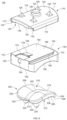
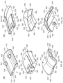
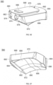
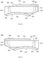
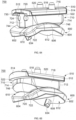
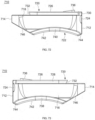
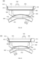
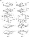
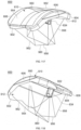
- the implant 100 includes a first member or tibia base 110, an insert 150, and a second member, talus component, or articulating member 200.
- the insert 150 includes a top surface 160 and a bottom surface 162. The top surface 160 of the insert 150 couples to the first member 110 and the bottom surface 162 engages the second member 200.
- the first member 110 includes a first end or anterior end 112 opposite a second end or posterior end 114.
- the first member 110 also includes a first side or medial side 116 opposite a second side or lateral side 118.
- the first member 110 includes a top surface 120 opposite a bottom surface 122.
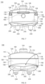
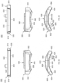
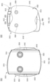
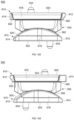
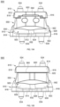
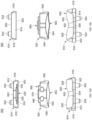
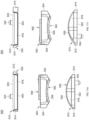
- the top surface 120 may include, for example, an arc shape or curvature extending between the first side 116 and the second side 118, as shown in FIGS. 7, 8 , 11 and 12 .
- the curvature may have, for example, an arc radius ranging from approximately 35 mm to 70 mm.
- the top surface 120 of the first member 110 may be, for example, flat as the top surface 120 extends between the first side 116 and the second side 118.
- the top surface 120 of the first member 110 may also include, for example, sloped, tapered, or angled sides on the first side 116 and the second side 118 of the first member 110.
- the angle of the sides of the top surface 120 at the first and second sides 116, 118 may be, for example, approximately 8° to 15° from vertical and more specifically approximately 10° from vertical.
- the edges of the first and second sides 116, 118 of the first member 110 may be, for example, rounded or curved.
- the rounded edges may have, for example, a radii of approximately 1.25 mm to 2.4 mm and more specifically approximately 1.75 mm to 2.4 mm.
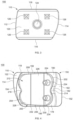
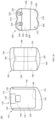
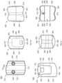
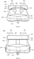
- the first member 110 may have an outer perimeter shape that may be, for example, a quadrilateral shape, such as, a generally trapezoidal shape from a top or bottom view, as shown in FIGS. 3, 4 , 15 , and 16 .
- the first and second sides 116, 118 may be generally parallel and the first end 112 and second end 114 may be, for example, angled or curved as they extend from the first side 116 to the second side 118.
- the length of the first or medial side 116 may be, for example, shorter than the length of the second or lateral side 118.
- the angle of the first end 112 may be, for example, smaller than the angle of the second end 114.
- the top surface 120, first side 116 and second side 118 may be, for example, textured or coated to provide a friction-stabilization surface and to allow for bone on-growth.
- the textured surface may be, for example, plasma sprayed biocompatible material, such as, commercially-pure titanium, or another biocompatible material as known by one of ordinary skill in the art.
- the top surface 120 of the first member 110 includes at least one peg or vertical peg 124 extending away from the top surface 120.
- the top surface 120 of the first member 110 also includes at least one protrusion, spike, pyramid, or cone 126 extending away from the top surface 120.
- the at least one protrusion 126 may be, for example, spaced from the at least one peg 124.
- the at least one protrusion 126 may be, for example, four protrusions 126, although alternative numbers of protrusions 126 are also contemplated.
- the protrusions 126 may be, for example, positioned equally spaced around the at least one peg 124.
- the at least one peg 124 and at least one protrusion 126 may not be, for example, textured, rather the at least one peg 124 and at least one protrusion 126 may be smooth to decrease bone resorption at the resection level.
- the bottom surface 122 of the first member 110 includes a recessed region or engagement region 128 extending into the first member 110 from the bottom surface 122 toward the top surface 120.
- the first member 110 may come in multiple sizes for use with patient's having different size tibia bones and the recessed region 128 of each of the first members 110 will be, for example, sized and shaped the same to allow for replacement of the first member 110 as needed.
- the bottom surface 122 also includes an engagement channel 130 extending from the first end 112 into the recessed region 128.
- the bottom surface 122 of the first member 110 includes a first engagement feature or first female dovetail portion 132 extending from the first side 116 into the recessed region 128, a second engagement feature or second female dovetail portion 134 extending from the second side 118 into the recessed region 128, and a third engagement feature or third female dovetail portion 136 extending from a position near the second end 114 into the recessed region 128.
- the bottom surface 122 of the first member 110 also includes a slot or removal engagement feature 138 and a locking groove 140 positioned adjacent to the slot 138.
- the slot 138 may be, for example, angled as the slot 138 extends from the first end 112 toward the locking groove 140.
- the second member, talus component or articulating member 200 has a first end or anterior end 202 opposite a second end or posterior end 204.
- the second member 200 also has a first side or medial side 206 opposite a second side or lateral side 208.
- the second member 200 has a top surface or articulating surface 210 opposite a bottom surface or bone engagement surface 212.
- the second member 200 may have, for example, a trapezium shape, as shown in FIGS. 15 and 16 .
- the first and second sides 206, 208 may be, for example, angled as the sides 206, 208 extend from the first end 202 to the second end 204.
- the sides 206, 208 may be angled, for example, approximately 5° to 12°, and more preferably approximately 10°, as they extend away from the first end 202.
- the first side 206 may be, for example, shorter than the second side 208.
- the second member 200 includes an anterior recess 214 extending into the first end 202.
- the anterior recess 214 may be, for example, positioned near a midpoint of a lateral axis of the second member 200 or, alternatively may be medially biased.
- the second member 200 also includes a posterior recess 216 extending into the second end 204.
- the posterior recess 216 may be, for example, positioned near a midpoint of the lateral axis of the second member 200 or, alternatively may be medially biased.
- the top surface 210 of the second member 200 includes a medial articulating surface 218 extending from the first side 206 of the second member 200 toward the second side 208.
- the top surface 210 may also include a lateral articulating surface 220 extending from the second side 208 of the second member 200 toward the first side 206.
- the top surface 210 also includes a central articulating portion 222 positioned at a point where the medial articulating surface 218 contacts the lateral articulating surface 220.
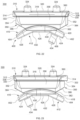
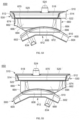
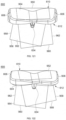
- the medial articulating surface 218 may include at least one first curvature along a longitudinal axis and at least one second curvature perpendicular to the longitudinal axis, as shown in FIG. 14 .
- the lateral articulating surface 220 has at least one third curvature along the longitudinal axis and at least one fourth curvature perpendicular to the longitudinal axis.
- the central articulating portion 222 may have a concave curvature on the top surface 210 of the second member 200 and the medial and lateral articulating surfaces 218, 220 may have convex curvatures on the top surface 210 of the second member 200.
- the articulating surface 210 of the second member 200 may include, for example, a coronal radii and the coronal radii may have, for example, a range of approximately 12 mm to 26 mm for a size 1 second member 200, a range of approximately 14 mm to 30 mm for a size 3 second member 200, and a range of approximately 17 mm to 34 mm for a size 5 second member 200.
- the articulating surface 210 of the second member 200 may include, for example, a sagittal radii and the sagittal radii may have, for example, a range of approximately 18 mm to 25 mm for a size 1 second member 200, a range of approximately 20 mm to 28 mm for a size 3 second member 200, and a range of approximately 21 mm to 30 mm for a size 5 second member 200.
- the bottom surface 212 of the second member 200 may include a first portion 224, a second portion 226, and a third portion 228.
- the first portion 224, the second portion 226, and the third portion 228 may each have, for example, planar surfaces.
- the second portion 226 may be positioned between the first portion 224 and the third portion 228.
- the first portion 224 may extend, for example, from the first end 202 to a first transition point 230.
- the second portion 226 may extend, for example, from the first transition point 230 to a second transition point 232.
- the third portion 228 may extend, for example, from the second transition point 232 to the second end 204.
- the first portion 224 may extend away from the second portion 226 at a first angle and the third portion 228 may extend away from the second portion 226 at a second angle.
- the first angle may be, for example, approximately 25° to 35°
- the second angle may be, for example, approximately 25° to 35°.
- the bottom surface 212 of the second member 200 may be, for example, coated or textured with a biocompatible material.
- the texture or coating may be, for example, a plasma sprayed material, such as, a commercially-pure titanium or other biocompatible material, as known by one of ordinary skill in the art.
- the bottom surface 212 of the second member 200 may also include at least one stem or peg 234 extending away from the first portion 224 of the bottom surface 212, as shown in FIGS. 1, 2 , 4-14 and 16 .
- the at least one stem 234 may be, for example, two stems 234, although other numbers of stems 234 are also contemplated.
- the first stem 234 is positioned on the first portion 224 between the anterior recess 214 and the first side 206 and the second stem 234 is positioned on the first portion 224 between the anterior recess 214 and the second side 208, as shown in FIGS. 10 and 16 .
- the stems 234 may be, for example, positioned slightly medially biased and may be offset, for example, approximately 1 mm from a midpoint of the second member 200.
- the at least one stem 234 may not be, for example, textured or coated, rather the at least one stem 234 may be smooth to decrease bone resorption at the resection level.
- the at least one stem 234 may have, for example, a cylindrical, pyramidal, or another quadrilateral prism shape.
- the insert 150 includes a first end or anterior end 152 opposite a second end or posterior end 154.
- the insert 150 also includes a first side or medial side 156 opposite a second side or lateral side 158.
- the insert 150 includes a top surface 160 opposite a bottom surface 162.
- the first end 152 of the insert 150 includes an opening or cylinder 164 extending into the insert 150 from the first end 152 toward the second end 154.
- the opening 164 may be sized and shaped or configured to receive an instrument, for example, a self-tapping screw to engage the insert 150 and remove the insert 150 from the first member 110.
- the top surface 160 of the insert 150 includes an engagement member or protrusion 166.
- the engagement member 166 includes a first engagement feature or first male dovetail 168 on the first side 156, a second engagement feature or second male dovetail 170 on the second side 158, and a third engagement feature or third male dovetail 172 on the second end 154.
- the first engagement feature 168 of the insert 150 may be configured or sized and shaped to engage the first engagement feature 132 of the first member 110
- the second engagement feature 170 of the insert 150 may be configured or sized and shaped to engage the second engagement feature 134 of the first member 110
- the third engagement feature 172 of the insert 150 may be configured or sized and shaped to engage the third engagement feature 136 of the first member 110.
- the top surface 160 also may include a slot or removal engagement feature 174 and a locking tab or protrusion 176.
- the slot 174 may be, for example, positioned near and open to the first end 152.
- the locking tab 176 may be, for example, positioned adjacent to the slot 174 and extend away from the top surface 160 of the insert 150.
- the locking tab 176 may be configured or sized and shaped to engage the locking groove 140 of the bottom surface 122 of the first member 110.
- the third arc radii R3 may be, for example, positioned adjacent to one of the second arc radii R2 on each side of the first member 310, such that a third arc radius R3 is positioned between one of the second arc radii R2 and the first side 316 and a third arc radius R3 is positioned between the other second arc radius R2 and the second side 318.
- the first arc radius R1 may be, for example, approximately 45 mm to 55 mm and more specifically, approximately 50 mm.
- the second arc radius R2 may be, for example, approximately 140 mm to 160 mm and more specifically approximately 150 mm.
- the fourth arc radius R4 may be positioned to the right of the flat or planar surface of the first end 312 and the fifth arc radius R5 may be positioned to the left of the flat or planar surface of the first end 312.
- the fourth and fifth arc radii R4, R5 may be, for example, approximately 3 mm to 5 mm, and more preferably approximately 4 mm.
- the sixth arc radius R6 may be positioned adjacent to the fourth arc radius R4 toward the first side 316 of the first member 310.
- the seventh arc radius R7 may be positioned adjacent to the fifth arc radius R5 toward the second side 318 of the first member 310.
- the first member 310 may have an outer perimeter shape that may be, for example, a quadrilateral shape, such as, a generally trapezoidal from a top or bottom view, as shown in FIGS. 20 , 32 and 33 .
- the first and second sides 316, 318 may be generally parallel and the first end 312 and second end 314 may be, for example, angled or curved as they extend from the first side 316 to the second side 318.
- the length of the first or medial side 316 may be, for example, shorter than the length of the second or lateral side 318.
- the angle or curvature of the first end 312 may be, for example, smaller than the angle of the second end 314.
- the top surface 360 of the insert 350 couples to a bottom surface 322 of the first member 310.
- the top surface 410 of the second member 400 is configured or sized and shaped to articulate with the bottom surface 362 of the insert 350.
- the medial articulating surface 418 of the second member 400 is configured to articulate with the first contact surface 378 of the insert 350
- the lateral articulating surface 420 of the second member 400 is configured to articulate with the second contact surface 380 of the insert 350
- the central portion 422 of the second member 400 is configured to articulate with the third contact surface 382 of the insert 350.
- the first member 510 may have an outer perimeter shape that may be, for example, a quadrilateral shape, such as, a generally trapezoidal from a top or bottom view, as shown in FIGS. 38 , 51 and 52 .
- the first and second sides 516, 518 may be generally parallel and the first end 512 and second end 514 may be, for example, angled or curved as they extend from the first side 516 to the second side 518.
- the length of the first or medial side 516 may be, for example, shorter than the length of the second or lateral side 518.
- the angle or curvature of the first end 512 may be, for example, smaller than the angle of the second end 514.
- the top surface 520 of the first member 510 includes at least one peg or vertical peg 524 extending away from the top surface 520.
- the at least one peg 524 may be, for example, two pegs 524, although alternative numbers of pegs 524 are also contemplated.
- the pegs 524 may be, for example, positioned equally spaced apart on the top surface 520 or alternatively, the two pegs 524 may be randomly positioned on the top surface 520.
- the at least one peg 524 may not be, for example, textured, rather the at least one peg 524 may be smooth to decrease bone resorption at the resection level.
- the bottom surface 522 of the first member 510 includes a recessed region or engagement region 528 extending into the first member 510 from the bottom surface 522 toward the top surface 520.
- the first member 510 may come in multiple sizes for use with patients having different size tibia bones and the recessed region 528 of each of the first members 510 will be, for example, sized and shaped the same to allow for replacement of the first member 510, as needed.
- the bottom surface 522 also includes an engagement channel 530 extending from the first end 512 into the recessed region 528.
- the bottom surface 522 of the first member 510 includes a first engagement feature or first female dovetail portion 532 extending from the first side 516 into the recessed region 528, a second engagement feature or second female dovetail portion 534 extending from the second side 518 into the recessed region 528, and a third engagement feature or third female dovetail portion 536 extending from a position near the second end 514 into the recessed region 528.
- the bottom surface 522 of the first member 510 also includes a slot or removal engagement feature 538 and a locking groove 540 positioned adjacent to the slot 538.
- the slot 538 may be, for example, angled as the slot 538 extends from the first end 512 toward the locking groove 540. As shown in FIG.
- the engagement channel 530 may have a first width at the opening at the first end 512 and a second width at the closed end near the second end 514.
- the first width may be, for example, wider than the second width.
- At least a portion of the first engagement feature 532 and at least a portion of the second engagement feature 534 may be, for example, tapered or curved between the first width at the opening of the first end 512 and the second width.
- the second width may extend from a position adjacent to the locking groove 540 to the closed end of the engagement channel 530.
- the second member, talus component or articulating member 600 has a first end or anterior end 602 opposite a second end or posterior end 604.
- the second member 600 also has a first side or medial side 606 opposite a second side or lateral side 608.
- the second member 600 has a top surface or articulating surface 610 opposite a bottom surface or bone engagement surface 612.
- the second member 600 may have, for example, a trapezium shape, as shown in FIGS. 50 and 51 .
- the first side 606 and second side 608 may be angled as they extend from the top surface 610 to the bottom surface 612 and the angle may be, for example, approximately 15° to 20° and more preferably approximately 10°.
- the first side 606 may be, for example, shorter than the second side 608. As shown in FIGS. 40, 41 , and 43 , at least a portion of the first and second sides 606, 608 may be, for example, angled or tapered from the top surface 610 toward the bottom surface 612.
- the second member 600 includes an anterior recess 614 extending into the first end 602. The anterior recess 614 may be, for example, positioned near a midpoint of a lateral axis of the second member 600 or, alternatively may be medially biased.
- the second member 600 also includes a posterior recess 616 extending into the second end 604. The posterior recess 616 may be, for example, positioned near a midpoint of the lateral axis of the second member 600 or, alternatively may be medially biased.
- the top surface 610 of the second member 600 includes a medial articulating surface 618 extending from the first side 606 of the second member 600 toward the second side 608.
- the top surface 610 may also include a lateral articulating surface 620 extending from the second side 608 of the second member 600 toward the first side 606.
- the top surface 610 also includes a central articulating portion 622 positioned at a point where the medial articulating surface 618 contacts the lateral articulating surface 620.
- the articulating surface 610 of the second member 600 may include, for example, at least one coronal radii and the at least one coronal radii may have, for example, a range of approximately 12 mm to 26 mm for a size 1 second member 600, a range of approximately 14 mm to 30 mm for a size 3 second member 600, and a range of approximately 17 mm to 34 mm for a size 5 second member 600.
- the bottom surface 612 of the second member 600 may include a first portion 624, a second portion 626, and a third portion 628.
- the first portion 624, the second portion 626, and the third portion 628 may each have, for example, planar surfaces.
- the second portion 626 may be positioned between the first portion 624 and the third portion 628.
- the first portion 624 may extend, for example, from the first end 602 to a first transition point 630.
- the second portion 626 may extend, for example, from the first transition point 630 to a second transition point 632.
- the third portion 628 may extend, for example, from the second transition point 632 to the second end 604.
- the first portion 624 may extend away from the second portion 626 at a first angle and the third portion 628 may extend away from the second portion 626 at a second angle.
- the first angle may be, for example, approximately 25° to 35°
- the second angle may be, for example, approximately 25° to 35°.
- the bottom surface 612 of the second member 600 may be, for example, coated or textured with a biocompatible material.
- the texture or coating may be, for example, a plasma sprayed material, such as, a commercially-pure titanium or other biocompatible material, as known by one of ordinary skill in the art.
- the bottom surface 612 of the second member 600 may also include at least one fin or stem 634 extending away from the first portion 624 of the bottom surface 612, as shown in FIGS. 36, 37 , 39-49 and 51 .
- the at least one fin 634 may be, for example, one fin 634, although other numbers of fins 634 are also contemplated.
- the first fin 634 is positioned on the first portion 624 aligned with the anterior recess 614, as shown in FIGS. 45 and 51 .
- the fin 634 may be, for example, tapered at the distal end.
- the at least one fin 634 may not be, for example, textured or coated, rather the at least one fin 634 may be smooth to decrease bone resorption at the resection level.
- the at least one fin 634 may have, for example, a cylindrical, round, oval or other like shape.
- the insert 550 includes a first end or anterior end 552 opposite a second end or posterior end 554.
- the insert 550 also includes a first side or medial side 556 opposite a second side or lateral side 558.
- the insert 550 includes a top surface 560 opposite a bottom surface 562.
- the first end 552 of the insert 550 includes at least one opening or cylinder 564 extending into the insert 550 from the first end 552 toward the second end 554.
- the at least one opening 564 may be sized and shaped or configured to receive an instrument or member, for example, a fastener or instrument to engage the insert 550 and remove the insert 550 from the first member 510.
- the first and second sides 556, 558 may be, for example, angled or tapered along at least a portion of the sides 556, 558 as the sides 556, 558 extend from the top surface 560 toward the bottom surface 562, as shown in FIGS. 42, 43 , 46 and 47 .
- the top surface 560 of the insert 550 includes an engagement member or protrusion 566.
- the engagement member 566 includes a first engagement feature or first male dovetail 568 near the first side 556, a second engagement feature or second male dovetail 570 near the second side 558, and a third engagement feature or third male dovetail 572 near the second end 554.
- the first engagement feature 568 of the insert 550 may be configured or sized and shaped to engage the first engagement feature 532 of the first member 510
- the second engagement feature 570 of the insert 550 may be configured or sized and shaped to engage the second engagement feature 534 of the first member 510
- the third engagement feature 572 of the insert 550 may be configured or sized and shaped to engage the third engagement feature 536 of the first member 510.
- the top surface 560 also includes a locking tab or protrusion 576. The locking tab 576 may, for example, extend away from the top surface 560 of the insert 550.
- the locking tab 576 may form, for example, a ramped portion extending from the top surface 560 of the insert 550 on the side positioned toward the second end 554 to a side positioned toward the first end 552.
- the side of the locking tab 576 positioned toward the first end 552 may have a height taller than the height of the side of the locking tab 576 positioned toward the second end 554.
- the locking tab 576 may be configured or sized and shaped to engage the locking groove 540 of the bottom surface 522 of the first member 510.
- the bottom surface 562 of the insert 550 includes a first contact surface or medial contact surface 578, a second contact surface or lateral contact surface 580, and a central contact surface 582.
- the first contact surface 578 extends along at least a portion of the bottom surface 562 in a medial-lateral direction from the first side 556 toward the second side 558.
- the first contact surface 578 also extends along at least a portion of the bottom surface 562 in an anterior-posterior direction from a position near the first end 552 toward a position near the second end 554.
- the second contact surface 580 extends along at least a portion of the bottom surface 562 from the second side 558 toward the first side 556.
- the centers of the radii of the bi-condylar surface may be, for example, spaced between approximately 18 mm and 26 mm for all sizes of the insert 550. More specifically, the centers of radii of the bi-condylar surface may be, for example, approximately 20 mm for a size 1 insert 550, approximately 22 mm for a size 3 insert 550, and approximately 24 mm for a size 5 insert 550.
- the first contact surface 578 includes at least one first curvature along a longitudinal axis and at least one second curvature along a lateral axis.
- the second contact surface 580 includes at least one third curvature along a longitudinal axis and at least one fourth curvature along a lateral axis.
- the central contact surface 582 includes at least one curvature.
- the curvatures of the first and second contact surfaces 578, 580 may be, for example, concave curvatures and the at least one curvature of the central contact surface 582 may be, for example, a convex curvature.
- the central contact surface 582 may provide, for example, stability in a medial-lateral direction.
- the central contact surface 582 may have, for example, a height ranging from approximately 1.5 mm and 2 mm.
- the insert 550 may also have a coronal radii and the coronal radii may be, for example, approximately 1.10 times the coronal radii of the talus.
- the insert 550 may have at least one sagittal radii.
- the at least one sagittal radii of the insert 550 may be, for example, multiple tangent and/or continuous radii, which may include varying levels of conformity with the sagittal radii of the second member 600.
- the sagittal radii may have, for example, a range of approximately 25 mm to 34 mm for all sizes of the insert 550. More specifically, the sagittal radii may be, for example, approximately 25 mm to 26 mm for the size 1 insert 550 and approximately 33 mm to 34 mm for the size 5 insert 550.
- the first angled portion 584 and the second angled portion 586 may alternatively be, for example, non-planar surfaces including at least one concave or convex curvature.
- the non-planar surfaces may, for example, still be angled or tapered between the ends 552, 554 and the contact surfaces 578, 580, 582 of the insert 550.
- the top surface 560 of the insert 550 couples to a bottom surface 522 of the first member 510.
- the top surface 610 of the second member 600 is configured or sized and shaped to articulate with the bottom surface 562 of the insert 550.
- the medial articulating surface 618 of the second member 600 is configured to articulate with the first contact surface 578 of the insert 550
- the lateral articulating surface 620 of the second member 600 is configured to articulate with the second contact surface 580 of the insert 550
- the central portion 622 of the second member 600 is configured to articulate with the third contact surface 582 of the insert 550.
- the implant 650 includes a first member or tibia base 510, an insert 660, and a second member, talus component, or articulating member 600.
- the first member 510 and the second member 600 may be of the type described above with reference to implant 500 and FIGS. 36-51 .
- the insert 660 includes a top surface 670 and a bottom surface 672. The top surface 670 of the insert 660 couples to the first member 510 and the bottom surface 672 engages the second member 600.
- the insert 660 includes a first end or anterior end 662 opposite a second end or posterior end 664.
- the insert 660 also includes a first side or medial side 666 opposite a second side or lateral side 668.
- the insert 660 includes a top surface 670 opposite a bottom surface 672.
- the first end 662 of the insert 660 includes at least one opening or cylinder 674 extending into the insert 660 from the first end 662 toward the second end 664.
- the at least one opening 674 may be sized and shaped or configured to receive an instrument or member, for example, a fastener or instrument to engage the insert 660 and remove the insert 660 from the first member 510.
- the first and second sides 666, 668 may be, for example, angled or tapered along at least a portion of the sides 666, 668 as the sides 666, 668 extend from the top surface 670 toward the bottom surface 672, as shown in FIGS. 52, 53 , 58 and 59 .
- the engagement member 676 also includes a second engagement feature or second male dovetail 680 near the second side 668, which is the same or similar to the second engagement feature or second male dovetail 570 and which will not be described again here in detail for brevity sake.
- the engagement member 676 may further include a third engagement feature or third male dovetail 682 near the second end 664, which is the same or similar to the third engagement feature or third male dovetail 572 and which will not be described again here in detail for brevity sake.
- the first engagement feature 678 of the insert 660 may be configured or sized and shaped to engage the first engagement feature 532 of the first member 510
- the second engagement feature 680 of the insert 660 may be configured or sized and shaped to engage the second engagement feature 534 of the first member 510
- the third engagement feature 682 of the insert 660 may be configured or sized and shaped to engage the third engagement feature 536 of the first member 510.
- the top surface 670 also includes a locking tab or protrusion 686.
- the locking tab 686 may be the same or similar to the locking tab 576 of insert 550 as described in greater detail above and which will not be described again here for brevity sake.
- the locking tab 686 may be configured or sized and shaped to engage the locking groove 540 of the bottom surface 522 of the first member 510.
- the bottom surface 672 of the insert 660 includes a first contact surface or medial contact surface 688, a second contact surface or lateral contact surface 690, and a central contact surface 692.
- the first contact surface 688 extends along at least a portion of the bottom surface 672 in a medial-lateral direction from the first side 666 toward the second side 668.
- the first contact surface 688 also extends along at least a portion of the bottom surface 672 in an anterior-posterior direction from a position near the first end 662 toward a position near the second end 662.
- the second contact surface 690 extends along at least a portion of the bottom surface 672 from the second side 668 toward the first side 666.
- the second contact surface 690 also extends along at least a portion of the bottom surface 672 in an anterior-posterior direction from a position near the first end 662 toward a position near the second end 664.
- the central contact surface or central sulcus 692 is positioned between the first contact surface 688 and the second contact surface 690.
- the central contact surface 692 also extends along at least a portion of the bottom surface 672 in an anterior-posterior direction from a position near the first end 662 toward a position near the second end 664.
- the first and second contact surfaces 688, 690 form a bi-condylar surface, as shown in FIGS. 52, 53 , and 57-59 .
- the centers of the radii of the bi-condylar surface may be, for example, spaced between approximately 18 mm and 26 mm for all sizes of the insert 660. More specifically, the centers of radii of the bi-condylar surface may be, for example, approximately 20 mm for a size 1 insert 660, approximately 22 mm for a size 3 insert 660, and approximately 24 mm for a size 5 insert 660.
- the first contact surface 688 includes at least one first curvature along a longitudinal axis and at least one second curvature along a lateral axis.
- the second contact surface 690 includes at least one third curvature along a longitudinal axis and at least one fourth curvature along a lateral axis.
- the central contact surface 692 includes at least one curvature.
- the curvatures of the first and second contact surfaces 688, 690 may be, for example, concave curvatures and the at least one curvature of the central contact surface 692 may be, for example, a convex curvature.
- the central contact surface 692 may provide, for example, stability in a medial-lateral direction.
- the central contact surface 692 may have, for example, a height ranging from approximately 1.5 mm and 2 mm.
- the insert 660 may also have a coronal radii and the coronal radii may be, for example, approximately 1.10 times the coronal radii of the talus.
- the insert 660 may have at least one sagittal radii.
- the at least one sagittal radii of the insert 660 may be, for example, multiple tangent and/or continuous radii, which may include varying levels of conformity with the sagittal radii of the second member 600.
- the sagittal radii may have, for example, a range of approximately 25 mm to 34 mm for all sizes of the insert 660. More specifically, the sagittal radii may be, for example, approximately 25 mm to 26 mm for the size 1 insert 660 and approximately 33 mm to 34 mm for the size 5 insert 660.
- the bottom surface 672 may also include, for example, a first angled or tapered portion 694 and a second angled or tapered portion 696.
- the first angled portion 694 may be, for example, positioned to extend from the first end 662 to the anterior portion of the contact surfaces 688, 690, 692 of the bottom surface 672 of the insert 660.
- the first angled portion 694 may be, for example, longer than the first angled portion 584 of the insert 550.
- the second angled portion 696 may be, for example, positioned to extend from the second end 664 to the posterior portion of the contact surfaces 688, 690, 692 of the bottom surface 672 of the insert 660.
- the top surface 670 of the insert 660 couples to a bottom surface 522 of the first member 510.
- the top surface 610 of the second member 600 is configured or sized and shaped to articulate with the bottom surface 672 of the insert 660.
- the medial articulating surface 618 of the second member 600 is configured to articulate with the first contact surface 688 of the insert 660
- the lateral articulating surface 620 of the second member 600 is configured to articulate with the second contact surface 690 of the insert 660
- the central portion 622 of the second member 600 is configured to articulate with the third contact surface 692 of the insert 660.
- the insert 710 includes a first end or anterior end 712 opposite a second end or posterior end 714.
- the insert 710 also includes a first side or medial side 716 opposite a second side or lateral side 718.
- the insert 710 includes a top surface 720 opposite a bottom surface 722.
- the first end 712 of the insert 710 includes at least one opening or cylinder 724 extending into the insert 710 from the first end 712 toward the second end 714.
- the at least one opening 724 may be sized and shaped or configured to receive an instrument or member, for example, a fastener or instrument to engage the insert 710 and remove the insert 710 from the first member 510.
- the first and second sides 716, 718 may be, for example, angled or tapered along at least a portion of the sides 716, 718 as the sides 716, 718 extend from the top surface 720 toward the bottom surface 722, as shown in FIGS. 64, 65 , 70 and 71 .
- the engagement member 726 also includes a second engagement feature or second male dovetail 730 near the second side 718, which is the same or similar to the second engagement feature or second male dovetail 570, 680 and which will not be described again here in detail for brevity sake.
- the engagement member 676 may further include a third engagement feature or third male dovetail 732 near the second end 714, which is the same or similar to the third engagement feature or third male dovetail 572, 682 and which will not be described again here in detail for brevity sake.
- the first engagement feature 728 of the insert 710 may be configured or sized and shaped to engage the first engagement feature 532 of the first member 510
- the second engagement feature 730 of the insert 710 may be configured or sized and shaped to engage the second engagement feature 534 of the first member 510
- the third engagement feature 732 of the insert 710 may be configured or sized and shaped to engage the third engagement feature 536 of the first member 510.
- the top surface 720 also includes a locking tab or protrusion 736.
- the locking tab 736 may be the same or similar to the locking tab 576, 686 of insert 550, 660, respectively, as described in greater detail above and which will not be described again here for brevity sake.
- the locking tab 736 may be configured or sized and shaped to engage the locking groove 540 of the bottom surface 522 of the first member 510.
- the bottom surface 722 of the insert 710 includes a first contact surface or medial contact surface 738, a second contact surface or lateral contact surface 740, and a central contact surface 742.
- the first contact surface 738 extends along at least a portion of the bottom surface 722 in a medial-lateral direction from the first side 716 toward the second side 718.
- the first contact surface 738 also extends along at least a portion of the bottom surface 722 in an anterior-posterior direction from a position near the first end 712 toward a position near the second end 714.
- the second contact surface 740 extends along at least a portion of the bottom surface 722 from the second side 718 toward the first side 716.
- the first contact surface 738 includes at least one first curvature along a longitudinal axis and at least one second curvature along a lateral axis.
- the second contact surface 740 includes at least one third curvature along a longitudinal axis and at least one fourth curvature along a lateral axis.
- the central contact surface 742 includes at least one curvature.
- the curvatures of the first and second contact surfaces 738, 740 may be, for example, concave curvatures and the at least one curvature of the central contact surface 742 may be, for example, a convex curvature.
- the central contact surface 742 may provide, for example, stability in a medial-lateral direction.
- the central contact surface 742 may have, for example, a height ranging from approximately 1.5 mm and 2 mm.
- the insert 710 may also have a coronal radii and the coronal radii may be, for example, approximately 1.10 times the coronal radii of the talus.
- the insert 710 may have at least one sagittal radii.
- the at least one sagittal radii of the insert 710 may be, for example, multiple tangent and/or continuous radii, which may include varying levels of conformity with the sagittal radii of the second member 600.
- the sagittal radii may have, for example, a range of approximately 25 mm to 34 mm for all sizes of the insert 710. More specifically, the sagittal radii may be, for example, approximately 25 mm to 26 mm for the size 1 insert 710 and approximately 33 mm to 34 mm for the size 5 insert 710.
- the bottom surface 722 may also include, for example, a first angled or tapered portion 744 and a second angled or tapered portion 746.
- the first angled portion 744 may be, for example, positioned to extend from the first end 712 to the anterior portion of the contact surfaces 738, 740, 742 of the bottom surface 722 of the insert 710.
- the first angled portion 744 may be, for example, shorter than the first angled portion 584 of the insert 550 and the first angled portion 694 of the insert 660.
- the second angled portion 746 may be, for example, positioned to extend from the second end 714 to the posterior portion of the contact surfaces 738, 740, 742 of the bottom surface 722 of the insert 710.
- the second angled portion 746 may be, for example, longer than the second angled portion 586 of the insert 550 and the second angled portion 696 of the insert 660.
- the first angled portion 744 and the second angled portion 746 may alternatively be, for example, non-planar surfaces including at least one concave or convex curvature.
- the non-planar surfaces may, for example, still be angled or tapered between the ends 744, 746 and the contact surfaces 738, 740, 742 of the insert 710.
- the top surface 720 of the insert 710 couples to a bottom surface 522 of the first member 510.
- the top surface 610 of the second member 600 is configured or sized and shaped to articulate with the bottom surface 722 of the insert 710.
- the medial articulating surface 618 of the second member 600 is configured to articulate with the first contact surface 738 of the insert 710
- the lateral articulating surface 620 of the second member 600 is configured to articulate with the second contact surface 740 of the insert 710
- the central portion 622 of the second member 600 is configured to articulate with the third contact surface 742 of the insert 710.
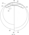
- the first member 510 and coupled insert 710 are positioned on the second member 600 such that the first member 510 and insert 710 are shifted in a posterior direction on the second member 600.
- the implant 700 includes an insert 710 to posteriorly shift the first member 510 relative to the second member 600 and the neutral positioning of implant 500.
Landscapes
- Health & Medical Sciences (AREA)
- Orthopedic Medicine & Surgery (AREA)
- Cardiology (AREA)
- Oral & Maxillofacial Surgery (AREA)
- Transplantation (AREA)
- Engineering & Computer Science (AREA)
- Biomedical Technology (AREA)
- Heart & Thoracic Surgery (AREA)
- Vascular Medicine (AREA)
- Life Sciences & Earth Sciences (AREA)
- Animal Behavior & Ethology (AREA)
- General Health & Medical Sciences (AREA)
- Public Health (AREA)
- Veterinary Medicine (AREA)
- Prostheses (AREA)
Claims (14)
- Un implant (100, 300, 500, 650, 700, 800, 900), comprenant :un premier élément (110, 310, 510, 810) ;un deuxième élément (200, 400, 600, 910), comprenant :
un composant talaire comprenant :une première extrémité (202, 402, 602, 912) opposée à une deuxième extrémité (204, 404, 604, 914) ;un premier côté (206, 406, 606, 916) opposé à un deuxième côté (208, 408, 608, 918) ; etune surface supérieure (210, 410, 610, 920) opposée à une surface inférieure (212, 412, 612, 922), la surface supérieure (210, 410, 610, 920) comprenant :une surface d'articulation médiale (218, 418, 618, 928) s'étendant à partir du premier côté (206, 406, 606, 916) en direction du deuxième côté (204, 404, 604, 914) du deuxième élément (200, 400, 600, 910), la surface d'articulation médiale (218, 418, 618, 928) présentant au moins une première courbure le long d'un axe longitudinal et au moins une deuxième courbure perpendiculairement à l'axe longitudinal ;une surface d'articulation latérale (220, 420, 620, 930) s'étendant à partir du deuxième côté (208, 408, 608, 918) du deuxième élément (200, 400, 600, 910) en direction du premier côté (206, 406, 606, 916), la surface d'articulation latérale (220, 420, 620, 930) présentant au moins une troisième courbure le long de l'axe longitudinal et au moins une quatrième courbure perpendiculairement à l'axe longitudinal ;la surface d'articulation médiale (218, 418, 618, 928) comportant un rayon sagittal antérieur-médial et un rayon sagittal postérieur-médial ; etla surface d'articulation latérale (220, 420, 620, 930) comportant un rayon sagittal antérieur-latéral et un rayon sagittal postérieur-latéral ; etun insert (150, 350, 550, 660, 710, 860) doté d'une surface supérieure (160, 360, 560, 670, 720, 870) et d'une surface inférieure (162, 362, 562, 672, 722, 872), la surface supérieure (160, 360, 560, 670, 720, 870) s'accouplant au premier élément (110, 310, 510, 810) et la surface inférieure (162, 362, 562, 672, 722, 872) entrant en prise avec le deuxième élément (200, 400, 600, 910), caractérisé en ce que le rayon sagittal antérieur-latéral est plus grand que le rayon sagittal antérieur-médial et le rayon sagittal postérieur-médial est plus grand que le rayon sagittal postérieur-latéral. - L'implant (100, 300, 500, 650, 700, 800, 900) de la revendication 1, dans lequel le premier élément (110, 310, 510, 810) comprend :une base tibiale (110, 310, 510, 810) ;une première extrémité (112, 312, 512, 812) opposée à une deuxième extrémité (114, 314, 514, 814) ;un premier côté (116, 316, 516, 816) opposé à un deuxième côté (118, 318, 518, 818) ; etune surface supérieure (120, 320, 520, 820) opposée à une surface inférieure (122, 322, 522, 822).
- L'implant (100, 300, 500, 650, 700, 800, 900) de la revendication 2, dans lequel la surface supérieure (120, 320, 520, 820) du premier élément (110, 310, 510, 810) comprend :au moins une goupille (124, 324, 524) s'étendant à l'opposé de la surface supérieure (120, 320, 520, 820) ; etau moins une saillie (126) s'étendant à l'opposé de la surface supérieure (120, 320, 520, 820), l'au moins une saillie (126) étant espacée de l'au moins une goupille (124, 324, 524).
- L'implant (300, 500, 650, 700) de l'une quelconque des revendications 2 et 3, dans lequel la surface supérieure (320, 520) du premier élément (310, 510) comprend :
de multiples rayons d'arc (R1, R2, R3) à mesure que la surface supérieure (320, 520) s'étend entre un premier côté (316, 516) et un deuxième côté (318, 518) du premier élément (310, 510), les multiples rayons d'arc (R1, R2, R3) comprenant :un premier rayon d'arc (R1) positionné près d'une portion centrale du premier élément (310, 510) ;des deuxièmes rayons d'arc (R2), un deuxième rayon d'arc (R2) étant positionné de manière adjacente au premier rayon d'arc (R1) en direction du premier côté (316, 516) du premier élément (310, 510) et un autre deuxième rayon d'arc (R2) étant positionné de manière adjacente au premier rayon d'arc (R1) en direction du deuxième côté (318, 518) du premier élément (310, 510) ; etdes troisièmes rayons d'arc (R3), un troisième rayon d'arc (R3) étant positionné de manière adjacente au deuxième rayon d'arc (R2) en direction du premier côté (316, 516) et un autre troisième rayon d'arc (R3) étant positionné de manière adjacente à l'autre deuxième rayon d'arc (R2) en direction du deuxième côté. - L'implant (100, 300, 500, 650, 700, 800, 900) de l'une quelconque des revendications 2, 3 et 4, dans lequel la surface inférieure (122, 322, 522, 822) du premier élément (110, 310, 510, 810) comprend :une région évidée (128, 328, 528) s'étendant jusque dans le premier élément (110, 310, 510, 810) à partir de la surface inférieure (122, 322, 522, 822) en direction de la surface supérieure (120, 320, 520, 820) ;un canal d'entrée en prise (130, 330, 532) s'étendant à partir de la première extrémité (112, 312, 512, 812) jusque dans la région évidée (128, 328, 528) ;une première caractéristique d'entrée en prise (132, 332, 532) s'étendant à partir du premier côté (116, 316, 516, 816) jusque dans la région évidée (128, 328, 528) ;une deuxième caractéristique d'entrée en prise (134, 334, 534) s'étendant à partir du deuxième côté (118, 318, 518, 818) jusque dans la région évidée (128, 328, 528) ;une troisième caractéristique d'entrée en prise (136, 336, 536) s'étendant à partir d'une position près de la deuxième extrémité (114, 314, 514, 814) jusque dans la région évidée (128, 328, 528), les première, deuxième et troisième caractéristiques d'entrée en prise (132, 332, 532, 134, 334, 534, 136, 336, 536) comprenant des portions en queue d'aronde femelle ;une fente (138, 338, 538) ; etune rainure de verrouillage (140, 340, 540) positionnée de manière adjacente à la fente (138, 338, 538), la fente (138, 338, 538) étant inclinée à mesure que la fente (138, 338, 538) s'étend à partir de la première extrémité (112, 312, 512, 812) en direction de la rainure de verrouillage (140, 340, 540).
- L'implant (100, 300, 500, 650, 700, 800, 900) de l'une quelconque des revendications 2 à 5, dans lequel le deuxième élément (200, 400, 600, 910) comprend :un évidement antérieur (214, 414, 614, 924) s'étendant jusque dans la première extrémité (202, 402, 602, 912) ; etun évidement postérieur (216, 416, 616, 926) s'étendant jusque dans la deuxième extrémité (204, 404, 604, 914).
- L'implant (100, 300, 500, 650, 700, 800, 900) de la revendication 6, dans lequel la surface supérieure (210, 410, 610, 920) du deuxième élément (200, 400, 600, 910) comprend :
une portion d'articulation centrale (222, 422, 622, 932) positionnée en un point où la surface d'articulation médiale (218, 418, 618, 928) entre en contact avec la surface d'articulation latérale (220, 420, 620, 930), la portion d'articulation centrale (222, 422, 622, 932) présentant une courbure concave sur la surface supérieure (210, 410, 610, 920) du deuxième élément (200, 400, 600, 910) et les surfaces d'articulation médiale et latérale (220, 420, 620, 930) présentant une courbure convexe sur la surface supérieure (210, 410, 610, 920) du deuxième élément (200, 400, 600, 910). - L'implant (100, 300, 500, 650, 700, 800) de l'une quelconque des revendications 6 et 7, dans lequel la surface inférieure (212, 412, 612) du deuxième élément (200, 400, 600) comprend :une première portion (224, 424, 624) s'étendant à partir de la première extrémité (202, 402, 602) jusqu'à un premier point de transition (230, 430, 630) ;une deuxième portion (226, 426, 626) s'étendant à partir du premier point de transition (230, 430, 630) jusqu'à un deuxième point de transition (232, 432, 632), la première portion (224, 424, 624) s'étendant à l'opposé de la deuxième portion (226, 426, 626) suivant un premier angle ; etune troisième portion (228, 428, 628) s'étendant à partir du deuxième point de transition (232, 432, 632) jusqu'à la deuxième extrémité (204, 404, 604),la deuxième portion (226, 426, 626) étant positionnée entre la première portion (224, 424, 624) et la troisième portion (228, 428, 628) et la troisième portion (228, 428, 628) s'étendant à l'opposé de la deuxième portion (226, 426, 626) suivant un deuxième angle ; etau moins une tige (234, 434, 634) s'étendant à l'opposé de la première portion (224, 424, 624) de la surface inférieure (212, 412, 612).
- L'implant (100, 300, 500, 650, 700, 800) de la revendication 8, dans lequel l'au moins une tige (234, 434, 634) est deux tiges (234, 434) et une première tige (234, 434) est positionnée sur la première portion (224, 424, 624) entre l'évidement antérieur (214, 414, 614) et le premier côté (206, 406, 606) et une deuxième tige (234, 434) est positionnée sur la première portion (224, 424, 624) entre l'évidement antérieur (214, 414, 614) et le deuxième côté (208, 408, 608).
- L'implant (100, 300, 500, 650, 700, 800, 900) de l'une quelconque des revendications 1 à 9, dans lequel l'insert (150, 350, 550, 660, 710, 860) comprend :un insert en polymère (150, 350, 550, 660, 710, 860) ;une première extrémité (152, 352, 552, 662, 712, 862) opposée à une deuxième extrémité (154, 354, 554, 664, 714, 864), la première extrémité (152, 352, 552, 662, 712, 862) de l'insert (150, 350, 550, 660, 710, 860) comprenant au moins une ouverture (164, 364, 564, 674, 724) s'étendant jusque dans l'insert (150, 350, 550, 660, 710, 860) à partir de la première extrémité (152, 352, 552, 662, 712, 862) en direction de la deuxième extrémité (154, 354, 554, 664, 714, 864) ;un premier côté (156, 356, 556, 666, 716, 866) opposé à un deuxième côté (158, 358, 558, 668, 718, 868) ; etune surface supérieure (160, 360, 560, 670, 720, 870) opposée à une surface inférieure (162, 362, 562, 672, 722, 872), la surface supérieure (160, 360, 560, 670, 720, 870) de l'insert (150, 350, 550, 660, 710, 860) comprenant :
un élément d'entrée en prise (166, 366, 566, 676, 726), l'élément d'entrée en prise (166, 366, 566, 676, 726) comprenant :une première caractéristique d'entrée en prise (168, 368, 568, 678, 728) sur un premier côté (156, 356, 556, 666, 716, 866) de l'élément d'entrée en prise (166, 366, 566, 676, 726) ;une deuxième caractéristique d'entrée en prise (170, 370, 570, 680, 730) sur un deuxième côté (158, 358, 558, 668, 718, 868) de l'élément d'entrée en prise (166, 366, 566, 676, 726) ; etune troisième caractéristique d'entrée en prise (172, 372, 572, 682, 732) sur une deuxième extrémité (154, 354, 554, 664, 714, 864) de l'élément d'entrée en prise (166, 366, 566, 676, 726). - L'implant (100, 300, 500, 650, 700, 800, 900) de la revendication 10, dans lequel la première caractéristique d'entrée en prise (168, 368, 568, 678, 728) est une première queue d'aronde mâle, la deuxième caractéristique d'entrée en prise (170, 370, 570, 680, 730) est une deuxième queue d'aronde mâle, et la troisième caractéristique d'entrée en prise (172, 372, 572, 682, 732) est une troisième queue d'aronde mâle.
- L'implant (100) de l'une quelconque des revendications 10 et 11, dans lequel la surface supérieure (160) comprend en outre :une fente (174) positionnée près de la première extrémité (152) et de manière ouverte sur celle-ci ; etune languette de verrouillage (176) positionnée de manière adjacente à la fente (174) et s'étendant à l'opposé de la surface supérieure (160) de l'insert (150), la languette de verrouillage (176) étant conçue pour entrer en prise avec la rainure de verrouillage (140) de la surface inférieure (122) du premier élément (110).
- L'implant (100, 300, 500, 650, 700, 800, 900) de l'une quelconque des revendications 10, 11 et 12, dans lequel la surface inférieure (162, 362, 562, 672, 722, 872) de l'insert (150, 350, 550, 660, 710, 860) comprend :une première surface de contact (178, 378, 578, 688, 738) s'étendant à partir du premier côté (156, 356, 556, 666, 716) de l'insert (150, 350, 550, 660, 710, 860) en direction du deuxième côté (158, 358, 558, 668, 718), la première surface de contact (178, 378, 578, 688, 738) comprenant au moins une première courbure le long d'un axe longitudinal et au moins une deuxième courbure le long d'un axe latéral ;une deuxième surface de contact (180, 380, 580, 690, 740) s'étendant à partir du deuxième côté (158, 358, 558, 668, 718, 868) de l'insert (150, 350, 550, 660, 710, 860) en direction du premier côté (156, 356, 556, 666, 716, 866), la deuxième surface de contact (180, 380, 580, 690, 740) comprenant au moins une troisième courbure le long d'un axe longitudinal et au moins une quatrième courbure le long d'un axe latéral ; et une surface de contact centrale (182, 382, 582, 692, 742) positionnée entre la première surface de contact (178, 378, 578, 688, 738) et la deuxième surface de contact (180, 380, 580, 690, 740).
- L'implant (100, 300, 500, 650, 700, 800, 900) de la revendication 13, dans lequel la première surface de contact (178, 378, 578, 688, 738) comporte au moins une première courbure concave, la deuxième surface de contact (180, 380, 580, 690, 740) comporte au moins une deuxième courbure concave, et la surface de contact centrale (182, 382, 582, 692, 742) comporte au moins une courbure convexe.
Applications Claiming Priority (2)
| Application Number | Priority Date | Filing Date | Title |
|---|---|---|---|
| US201862661945P | 2018-04-24 | 2018-04-24 | |
| PCT/US2019/029009 WO2020013901A2 (fr) | 2018-04-24 | 2019-04-24 | Implants et procédés d'utilisation et d'assemblage |
Publications (4)
| Publication Number | Publication Date |
|---|---|
| EP3784148A2 EP3784148A2 (fr) | 2021-03-03 |
| EP3784148A4 EP3784148A4 (fr) | 2022-01-19 |
| EP3784148B1 true EP3784148B1 (fr) | 2025-07-02 |
| EP3784148C0 EP3784148C0 (fr) | 2025-07-02 |
Family
ID=69142290
Family Applications (1)
| Application Number | Title | Priority Date | Filing Date |
|---|---|---|---|
| EP19834470.7A Active EP3784148B1 (fr) | 2018-04-24 | 2019-04-24 | Implants |
Country Status (6)
| Country | Link |
|---|---|
| US (3) | US11219530B2 (fr) |
| EP (1) | EP3784148B1 (fr) |
| AU (2) | AU2019302325B2 (fr) |
| CA (1) | CA3098384A1 (fr) |
| ES (1) | ES3036034T3 (fr) |
| WO (1) | WO2020013901A2 (fr) |
Families Citing this family (10)
| Publication number | Priority date | Publication date | Assignee | Title |
|---|---|---|---|---|
| AU2019302325B2 (en) | 2018-04-24 | 2024-05-02 | Paragon 28, Inc. | Implants and methods of use and assembly |
| KR102315484B1 (ko) * | 2020-03-30 | 2021-10-22 | 주식회사 코렌텍 | 인공발목관절 베어링요소 |
| CN111920551A (zh) * | 2020-07-28 | 2020-11-13 | 北京市春立正达医疗器械股份有限公司 | 一种初次全踝关节假体 |
| GB2599100B (en) * | 2020-09-23 | 2023-02-08 | Rlfa Consultants Ltd | An ankle prosthesis |
| US12127946B2 (en) * | 2021-04-01 | 2024-10-29 | Wright Medical Technology, Inc. | Low-profile prostheses, systems, and methods |
| USD1024325S1 (en) * | 2021-05-28 | 2024-04-23 | Depuy Ireland Unlimited Company | Distal cutting block |
| US12201538B2 (en) * | 2021-09-21 | 2025-01-21 | Wright Medical Technology, Inc. | Expanding tibial stem |
| WO2023102158A1 (fr) | 2021-12-03 | 2023-06-08 | Arthrex, Inc. | Conception d'élément astraglien anatomique pour remplacement total de la cheville |
| JP2025502366A (ja) * | 2022-01-18 | 2025-01-24 | パラゴン28・インコーポレイテッド | 関節形成術のためのシステム、インプラント、および方法 |
| WO2023250428A2 (fr) * | 2022-06-22 | 2023-12-28 | Paragon 28, Inc. | Implants orthopédiques et instruments |
Family Cites Families (95)
| Publication number | Priority date | Publication date | Assignee | Title |
|---|---|---|---|---|
| US3975778A (en) | 1975-07-14 | 1976-08-24 | Newton Iii St Elmo | Total ankle arthroplasty |
| US4021864A (en) | 1976-04-14 | 1977-05-10 | The Regents Of The University Of California | Ankle prosthesis |
| US4069518A (en) | 1976-08-31 | 1978-01-24 | Groth Jr Harry E | Total ankle prosthesis |
| US5326365A (en) | 1992-04-10 | 1994-07-05 | Alvine Franklin G | Ankle implant |
| FR2700462B1 (fr) | 1993-01-19 | 1995-04-21 | Medimplant | Appareillage d'implantation d'une prothèse articulaire. |
| US5702464A (en) | 1996-02-20 | 1997-12-30 | Smith & Nephew Inc. | Modular trial tibial insert |
| US8480754B2 (en) * | 2001-05-25 | 2013-07-09 | Conformis, Inc. | Patient-adapted and improved articular implants, designs and related guide tools |
| IT1310371B1 (it) | 1999-05-13 | 2002-02-13 | Ist Ortopedici Rizzoli | Dispositivo di protesi per articolazione umana, in particolare perarticolazione della tibotarsica e relativo metodo di impianto. |
| FR2800601B1 (fr) | 1999-11-05 | 2002-01-04 | Europ Foot Platform | Prothese de cheville |
| DE10123124C1 (de) * | 2001-05-03 | 2002-12-19 | Eska Implants Gmbh & Co | Sprunggelenkendoprothese |
| WO2003045287A2 (fr) * | 2001-11-28 | 2003-06-05 | Wright Medical Technology, Inc. | Endoprothese du genou |
| DE10213063B4 (de) | 2002-03-22 | 2004-02-05 | Hjs Gelenk System Gmbh | Künstliches Gelenk |
| US7615082B2 (en) | 2002-03-22 | 2009-11-10 | Hjs Gelenk System Gmbh | Artificial joint |
| US6863691B2 (en) | 2002-04-29 | 2005-03-08 | Timothy J. Short | Ankle implant |
| US7025790B2 (en) | 2002-06-27 | 2006-04-11 | Concepts In Medicine Iii, L.L.C. | Ankle joint prosthesis and its method of implantation |
| EP2671538A1 (fr) | 2003-01-16 | 2013-12-11 | Massachusetts General Hospital | Procédés de fabrication de matériau polymère résistant à l'oxydation |
| US20040167631A1 (en) | 2003-02-21 | 2004-08-26 | Kenny Luchesi | Fixation surface for ankle prosthesis |
| US20040186585A1 (en) | 2003-03-21 | 2004-09-23 | Lawrence Feiwell | Sphere-on-sphere ankle prosthesis |
| JP4191194B2 (ja) | 2003-08-27 | 2008-12-03 | ヴァルデマール・リンク・ゲゼルシャフト・ミット・ベシュレンクテル・ハフツング・ウント・コムパニー・コマンディットゲゼルシャフト | 足関節エンドプロテーゼ |
| US7534270B2 (en) | 2003-09-03 | 2009-05-19 | Integra Lifesciences Corporation | Modular total ankle prosthesis apparatuses and methods |
| JP4440212B2 (ja) | 2003-10-02 | 2010-03-24 | コンセプツ・イン・メディシン・サード・エルエルシー | 踝関節プロテーゼ |
| WO2005037135A2 (fr) | 2003-10-14 | 2005-04-28 | The University Of Iowa Research Foundation | Prothese de cheville et procede de pose d'une prothese de cheville |
| US7323012B1 (en) | 2004-03-17 | 2008-01-29 | Biomet Manufacturing Corp. | Ankle implant |
| US20050288792A1 (en) | 2004-06-23 | 2005-12-29 | Landes Mark D | Modular ankle prosthesis and associated method |
| WO2006023824A2 (fr) | 2004-08-19 | 2006-03-02 | Kinetikos Medical Incorporated | Appareils, systemes et procedes modulaires de prothese totale de la cheville, et systemes et procedes pour la resection osseuse et l'implantation prothetique |
| US20060149372A1 (en) * | 2004-12-17 | 2006-07-06 | Paxson Robert D | Artificial spinal disc |
| CA2601090C (fr) | 2005-03-14 | 2013-08-20 | Inbone Technologies, Inc. | Prothese de cheville |
| US20060247788A1 (en) | 2005-03-31 | 2006-11-02 | The Regents Of The University Of California | Total ankle arthroplasty |
| ZA200704470B (en) | 2005-06-24 | 2008-08-27 | De Villiers Malan | Ankle prosthesis |
| EP1981439A4 (fr) | 2006-01-20 | 2013-02-06 | Gmbh Synthes | Procede de preparation au remplacement d'une articulation tibio-tarsienne, prothese d'articulation et appareil d'alignement de coupe a utiliser lors d'une procedure d'arthroplastie |
| FR2896404B1 (fr) | 2006-01-24 | 2008-02-29 | Tornier Sas | Ensemble d'instrumentation chirurgicale pour poser une prothese de cheville |
| US9278006B2 (en) | 2006-10-26 | 2016-03-08 | European Foot Platform Sc | Ankle prosthesis with neutral position adjustment |
| GB2445146C (en) | 2006-12-23 | 2016-03-23 | Corin Ltd | Improvements in and relating to an ankle prosthesis |
| US8147557B2 (en) | 2007-03-30 | 2012-04-03 | Depuy Products, Inc. | Mobile bearing insert having offset dwell point |
| US20080287976A1 (en) * | 2007-05-14 | 2008-11-20 | Weaner Lauren S | Gastric band with engagement member |
| US8641959B2 (en) | 2007-07-27 | 2014-02-04 | Biomet Manufacturing, Llc | Antioxidant doping of crosslinked polymers to form non-eluting bearing components |
| US8546460B2 (en) | 2007-09-04 | 2013-10-01 | Smith & Nephew, Inc. | Ultra high molecular weight polyethylene for bearing surfaces |
| US10398561B2 (en) | 2007-09-26 | 2019-09-03 | DePuy Synthes Products, Inc. | Talar implant system and method |
| US20100057216A1 (en) * | 2008-07-23 | 2010-03-04 | Jamy Gannoe | System and method for joint resurfacing with dynamic fixation |
| EP2913030B1 (fr) | 2008-09-30 | 2018-03-21 | Wright Medical Technology, Inc. | Prothèse de cheville et composant tibial correspondant |
| US9539044B2 (en) * | 2009-04-13 | 2017-01-10 | George John Lian | Systems and instrumentalities for use in removal of tibial prostheses of total ankle replacements |
| US8337503B2 (en) | 2009-04-13 | 2012-12-25 | George John Lian | Custom radiographically designed cutting guides and instruments for use in total ankle replacement surgery |
| US20110035019A1 (en) | 2009-07-09 | 2011-02-10 | Wright State University | Total ankle replacement system |
| US8906105B2 (en) * | 2009-08-11 | 2014-12-09 | Michael D. Ries | Systems and methods for mobile bearing prosthetic knee |
| WO2011101699A1 (fr) | 2010-02-19 | 2011-08-25 | Newdeal | Prothèse de cheville avec ajustement simplifié |
| US9132209B2 (en) | 2010-05-07 | 2015-09-15 | Howmedia Osteonics Corp. | Surface crosslinked polyethylene |
| US8591596B2 (en) | 2010-05-28 | 2013-11-26 | DePuy Synthes Products, LLC | Semi-constrained ankle prosthesis having a rotating bearing insert |
| WO2012018563A1 (fr) * | 2010-07-24 | 2012-02-09 | Zimmer, Inc. | Prothèse tibiale |
| US20120267819A1 (en) | 2011-04-22 | 2012-10-25 | Biomet Manufacturing Corp. | Antioxidant doping of crosslinked polymers at high pressures |
| FR2986415A1 (fr) | 2012-02-06 | 2013-08-09 | Tornier Sa | Ensemble d'instrumentation chirurgicale pour poser une prothese de cheville |
| EP2649966A1 (fr) | 2012-04-12 | 2013-10-16 | Arthrex, Inc. | Implant de surface de talus |
| EP2856978B8 (fr) | 2012-05-31 | 2017-12-13 | KYOCERA Corporation | Revetement pour implant et son procédé de fabrication |
| US9750613B2 (en) | 2012-11-12 | 2017-09-05 | Wright Medical Technology, Inc. | Stabilized total ankle prosthesis |
| US9974588B2 (en) | 2012-12-27 | 2018-05-22 | Wright Medical Technology, Inc. | Ankle replacement system and method |
| US10080573B2 (en) | 2012-12-27 | 2018-09-25 | Wright Medical Technology, Inc. | Ankle replacement system and method |
| US9918724B2 (en) | 2012-12-27 | 2018-03-20 | Wright Medical Technology, Inc. | Ankle replacement system and method |
| WO2014149952A1 (fr) | 2013-03-15 | 2014-09-25 | Drexel University | Cheville prothétique ayant une articulation en forme de selle conique |
| EP2832321A1 (fr) | 2013-08-01 | 2015-02-04 | Universitätsspital Basel | Système d'implant pour remplacement total de la cheville |
| ITMI20131590A1 (it) | 2013-09-26 | 2015-03-27 | Ciquadro Snc Di Carboni Sebastiano | Protesi di caviglia |
| US9861491B2 (en) | 2014-04-30 | 2018-01-09 | Depuy Ireland Unlimited Company | Tibial trial system for a knee prosthesis |
| EP3603579A1 (fr) | 2014-05-12 | 2020-02-05 | Integra LifeSciences Corporation | Prothèse totale de la cheville |
| EP4201349B1 (fr) | 2014-08-22 | 2025-09-10 | Wright Medical Technology, Inc. | Implant de révision talaire |
| CA2896943C (fr) | 2014-09-12 | 2017-06-27 | Wright Medical Technology, Inc. | Prothese de dome d'astragale |
| US9579210B2 (en) | 2014-11-07 | 2017-02-28 | Wright Medical Technology, Inc. | Talar dome fixation stem |
| US10456265B2 (en) | 2015-01-07 | 2019-10-29 | Wright Medical Technology, Inc. | Fixation mechanism for an implant |
| CA3005230C (fr) | 2015-01-12 | 2021-11-09 | Wright Medical Technology, Inc. | Vis ciblee pour la fixation du dome astragalien |
| AU2016388305B2 (en) | 2015-01-20 | 2019-06-06 | Advita Ortho, LLC. | Talar implant for modifying joint kinematics |
| EP3056171B1 (fr) * | 2015-02-13 | 2019-03-13 | InnoLux Corporation | Prothèse d'articulation du genou, composant tibial et composant fémoral de celui-ci |
| EP3649990B1 (fr) | 2015-04-17 | 2022-07-06 | Wright Medical Technology, Inc. | Dôme astragalien intra-osseux comportant des pattes extensibles |
| US20170049575A1 (en) | 2015-08-18 | 2017-02-23 | Wright Medical Technology, Inc. | Modular talar fixation method and system |
| US20170056188A1 (en) | 2015-08-25 | 2017-03-02 | Wright Medical Technology, Inc. | Total ankle talar prosthesis with anchor holes and grooves |
| US9877839B2 (en) | 2015-08-25 | 2018-01-30 | Wright Medical Technology, Inc. | Modular talar fixation method and system |
| DK3163983T3 (da) | 2015-10-28 | 2020-08-24 | Vito Nv | Apparat til plasmabehandling med indirekte atmosfærisk tryk |
| EP3405144B1 (fr) | 2016-01-20 | 2023-10-25 | Exactech, Inc. | Implant astraglien pour modifier la cinématique d'articulation |
| AU2016400080B2 (en) | 2016-03-28 | 2019-10-17 | Wright Medical Technology, Inc. | Anterior resurfacing talar plate |
| US10136998B2 (en) | 2016-08-30 | 2018-11-27 | Wright Medical Technology, Inc. | Revision total ankle implants |
| WO2018053439A1 (fr) | 2016-09-16 | 2018-03-22 | Dt Medtech, Llc | Prothèses de cheville et leurs procédés d'utilisation |
| EP3551138B1 (fr) | 2017-05-04 | 2023-09-06 | Wright Medical Technology, Inc. | Implants osseux comportant des entretoises |
| US10182832B1 (en) * | 2017-08-24 | 2019-01-22 | Limacorporate S.P.A. | Ankle arthroplasty systems and methods |
| AU2018322380B2 (en) | 2017-08-24 | 2024-06-13 | Limacorporate S.P.A. | Ankle arthroplasty systems and methods |
| US10485561B2 (en) | 2017-08-24 | 2019-11-26 | Limacorporate S.P.A. | Ankle arthroplasty system and methods |
| KR102018051B1 (ko) | 2017-08-29 | 2019-09-04 | 주식회사 코렌텍 | 인공발목관절 경골요소 |
| KR102066837B1 (ko) | 2017-08-29 | 2020-01-16 | 주식회사 코렌텍 | 인공발목관절 거골요소 |
| FR3070593A1 (fr) | 2017-09-05 | 2019-03-08 | In2Bones | Prothese de cheville amelioree |
| EP3769724B1 (fr) | 2017-09-22 | 2022-03-02 | Encore Medical, L.P. dba DJO Surgical | Implant de cheville astragalien |
| FR3071400B1 (fr) | 2017-09-28 | 2019-10-04 | Biotechni | Prothese de cheville comportant un implant talien, un implant tibial et un insert, kit incluant au moins une telle prothese, et guide de coupe pour la mise en place de l'implant tibial |
| WO2019090022A1 (fr) * | 2017-11-02 | 2019-05-09 | Schweitzer Jr Karl M | Dispositif de remplacement d'articulation sous-astragalienne et procédé d'arthroplastie |
| AU2019302325B2 (en) | 2018-04-24 | 2024-05-02 | Paragon 28, Inc. | Implants and methods of use and assembly |
| FR3081099B1 (fr) | 2018-05-17 | 2021-07-09 | I Ceram | Prothese de cheville avec un meplat |
| TWI786139B (zh) | 2018-06-22 | 2022-12-11 | 財團法人工業技術研究院 | 人工關節 |
| US20200085585A1 (en) | 2018-09-14 | 2020-03-19 | Drexel University | Total ankle replacement with anatomically fitted talar component |
| US11013608B2 (en) | 2018-09-21 | 2021-05-25 | Wright Medical Technology, Inc. | Talar bone plate |
| TR201819753A2 (tr) | 2018-12-18 | 2020-07-21 | Dokuz Eyluel Ueniversitesi Rektoerluegue | Bi̇r ayak bi̇leği̇ protezi̇ |
| EP3698761B1 (fr) | 2019-02-22 | 2021-11-17 | Stryker European Operations Limited | Prothèse totale de la cheville |
| US10940012B2 (en) | 2019-03-11 | 2021-03-09 | Wright Medical Technology, Inc. | Talar dome with angled holes |
-
2019
- 2019-04-24 AU AU2019302325A patent/AU2019302325B2/en active Active
- 2019-04-24 EP EP19834470.7A patent/EP3784148B1/fr active Active
- 2019-04-24 ES ES19834470T patent/ES3036034T3/es active Active
- 2019-04-24 CA CA3098384A patent/CA3098384A1/fr active Pending
- 2019-04-24 WO PCT/US2019/029009 patent/WO2020013901A2/fr not_active Ceased
-
2020
- 2020-10-24 US US16/949,310 patent/US11219530B2/en active Active
-
2022
- 2022-01-11 US US17/647,646 patent/US12502281B2/en active Active
-
2024
- 2024-07-31 AU AU2024205246A patent/AU2024205246A1/en active Pending
-
2025
- 2025-12-23 US US19/431,585 patent/US20260115003A1/en active Pending
Also Published As
| Publication number | Publication date |
|---|---|
| WO2020013901A2 (fr) | 2020-01-16 |
| AU2019302325A1 (en) | 2020-12-10 |
| AU2024205246A1 (en) | 2024-08-22 |
| US11219530B2 (en) | 2022-01-11 |
| AU2019302325B2 (en) | 2024-05-02 |
| WO2020013901A3 (fr) | 2020-03-19 |
| US20220125595A1 (en) | 2022-04-28 |
| EP3784148C0 (fr) | 2025-07-02 |
| US12502281B2 (en) | 2025-12-23 |
| CA3098384A1 (fr) | 2020-01-16 |
| US20260115003A1 (en) | 2026-04-30 |
| ES3036034T3 (en) | 2025-09-12 |
| EP3784148A4 (fr) | 2022-01-19 |
| US20210038402A1 (en) | 2021-02-11 |
| EP3784148A2 (fr) | 2021-03-03 |
| WO2020013901A9 (fr) | 2020-02-13 |
Similar Documents
| Publication | Publication Date | Title |
|---|---|---|
| US11219530B2 (en) | Implants and methods of use and assembly | |
| US9937058B2 (en) | Prosthetic implant and method of implantation | |
| US8147558B2 (en) | Mobile bearing assembly having multiple articulation interfaces | |
| US8147557B2 (en) | Mobile bearing insert having offset dwell point | |
| US20080243261A1 (en) | Mobile bearing assembly having a closed track | |
| US20060122705A1 (en) | Hydroxyapatite backed glenoid prosthesis | |
| EP2774582B1 (fr) | Prothèse du genou à roulement fixe | |
| US20230115254A1 (en) | Implants and methods of use, assembly and fabrication | |
| US20210298920A1 (en) | Trial insert assembly | |
| EP3821853B1 (fr) | Arthroplastie totale du genou à quille concentrique | |
| EP3834779A1 (fr) | Système d'instrument chirurgical orthopédique ayant un essai d'appui tibial à chargement antérieur et procédé chirurgical associé pour l'utiliser |
Legal Events
| Date | Code | Title | Description |
|---|---|---|---|
| STAA | Information on the status of an ep patent application or granted ep patent |
Free format text: STATUS: THE INTERNATIONAL PUBLICATION HAS BEEN MADE |
|
| PUAI | Public reference made under article 153(3) epc to a published international application that has entered the european phase |
Free format text: ORIGINAL CODE: 0009012 |
|
| STAA | Information on the status of an ep patent application or granted ep patent |
Free format text: STATUS: REQUEST FOR EXAMINATION WAS MADE |
|
| 17P | Request for examination filed |
Effective date: 20201120 |
|
| AK | Designated contracting states |
Kind code of ref document: A2 Designated state(s): AL AT BE BG CH CY CZ DE DK EE ES FI FR GB GR HR HU IE IS IT LI LT LU LV MC MK MT NL NO PL PT RO RS SE SI SK SM TR |
|
| AX | Request for extension of the european patent |
Extension state: BA ME |
|
| DAV | Request for validation of the european patent (deleted) | ||
| DAX | Request for extension of the european patent (deleted) | ||
| REG | Reference to a national code |
Ipc: A61F0002420000 Ref country code: DE Ref legal event code: R079 Ref document number: 602019072047 Country of ref document: DE Free format text: PREVIOUS MAIN CLASS: A61B0017080000 |
|
| A4 | Supplementary search report drawn up and despatched |
Effective date: 20211217 |
|
| RIC1 | Information provided on ipc code assigned before grant |
Ipc: A61F 5/00 20060101ALI20211213BHEP Ipc: A61F 2/38 20060101ALI20211213BHEP Ipc: A61F 2/30 20060101ALI20211213BHEP Ipc: A61F 2/28 20060101ALI20211213BHEP Ipc: A61B 17/56 20060101ALI20211213BHEP Ipc: A61B 17/3209 20060101ALI20211213BHEP Ipc: A61B 17/08 20060101ALI20211213BHEP Ipc: A61F 2/42 20060101AFI20211213BHEP |
|
| GRAP | Despatch of communication of intention to grant a patent |
Free format text: ORIGINAL CODE: EPIDOSNIGR1 |
|
| STAA | Information on the status of an ep patent application or granted ep patent |
Free format text: STATUS: GRANT OF PATENT IS INTENDED |
|
| INTG | Intention to grant announced |
Effective date: 20250129 |
|
| GRAS | Grant fee paid |
Free format text: ORIGINAL CODE: EPIDOSNIGR3 |
|
| GRAA | (expected) grant |
Free format text: ORIGINAL CODE: 0009210 |
|
| STAA | Information on the status of an ep patent application or granted ep patent |
Free format text: STATUS: THE PATENT HAS BEEN GRANTED |
|
| AK | Designated contracting states |
Kind code of ref document: B1 Designated state(s): AL AT BE BG CH CY CZ DE DK EE ES FI FR GB GR HR HU IE IS IT LI LT LU LV MC MK MT NL NO PL PT RO RS SE SI SK SM TR |
|
| REG | Reference to a national code |
Ref country code: GB Ref legal event code: FG4D |
|
| REG | Reference to a national code |
Ref country code: CH Ref legal event code: EP |
|
| REG | Reference to a national code |
Ref country code: DE Ref legal event code: R096 Ref document number: 602019072047 Country of ref document: DE |
|
| REG | Reference to a national code |
Ref country code: IE Ref legal event code: FG4D |
|
| U01 | Request for unitary effect filed |
Effective date: 20250716 |
|
| U07 | Unitary effect registered |
Designated state(s): AT BE BG DE DK EE FI FR IT LT LU LV MT NL PT RO SE SI Effective date: 20250723 |
|
| REG | Reference to a national code |
Ref country code: ES Ref legal event code: FG2A Ref document number: 3036034 Country of ref document: ES Kind code of ref document: T3 Effective date: 20250912 |
|
| PG25 | Lapsed in a contracting state [announced via postgrant information from national office to epo] |
Ref country code: IS Free format text: LAPSE BECAUSE OF FAILURE TO SUBMIT A TRANSLATION OF THE DESCRIPTION OR TO PAY THE FEE WITHIN THE PRESCRIBED TIME-LIMIT Effective date: 20251102 |
|
| PG25 | Lapsed in a contracting state [announced via postgrant information from national office to epo] |
Ref country code: NO Free format text: LAPSE BECAUSE OF FAILURE TO SUBMIT A TRANSLATION OF THE DESCRIPTION OR TO PAY THE FEE WITHIN THE PRESCRIBED TIME-LIMIT Effective date: 20251002 |
|
| PG25 | Lapsed in a contracting state [announced via postgrant information from national office to epo] |
Ref country code: HR Free format text: LAPSE BECAUSE OF FAILURE TO SUBMIT A TRANSLATION OF THE DESCRIPTION OR TO PAY THE FEE WITHIN THE PRESCRIBED TIME-LIMIT Effective date: 20250702 |
|
| PG25 | Lapsed in a contracting state [announced via postgrant information from national office to epo] |
Ref country code: GR Free format text: LAPSE BECAUSE OF FAILURE TO SUBMIT A TRANSLATION OF THE DESCRIPTION OR TO PAY THE FEE WITHIN THE PRESCRIBED TIME-LIMIT Effective date: 20251003 |
|
| PG25 | Lapsed in a contracting state [announced via postgrant information from national office to epo] |
Ref country code: CZ Free format text: LAPSE BECAUSE OF FAILURE TO SUBMIT A TRANSLATION OF THE DESCRIPTION OR TO PAY THE FEE WITHIN THE PRESCRIBED TIME-LIMIT Effective date: 20250702 |
|
| PG25 | Lapsed in a contracting state [announced via postgrant information from national office to epo] |
Ref country code: PL Free format text: LAPSE BECAUSE OF FAILURE TO SUBMIT A TRANSLATION OF THE DESCRIPTION OR TO PAY THE FEE WITHIN THE PRESCRIBED TIME-LIMIT Effective date: 20250702 |
|
| PG25 | Lapsed in a contracting state [announced via postgrant information from national office to epo] |
Ref country code: RS Free format text: LAPSE BECAUSE OF FAILURE TO SUBMIT A TRANSLATION OF THE DESCRIPTION OR TO PAY THE FEE WITHIN THE PRESCRIBED TIME-LIMIT Effective date: 20251002 |
|
| PG25 | Lapsed in a contracting state [announced via postgrant information from national office to epo] |
Ref country code: SM Free format text: LAPSE BECAUSE OF FAILURE TO SUBMIT A TRANSLATION OF THE DESCRIPTION OR TO PAY THE FEE WITHIN THE PRESCRIBED TIME-LIMIT Effective date: 20250702 |
|
| PGFP | Annual fee paid to national office [announced via postgrant information from national office to epo] |
Ref country code: GB Payment date: 20260319 Year of fee payment: 8 |
|
| PG25 | Lapsed in a contracting state [announced via postgrant information from national office to epo] |
Ref country code: SK Free format text: LAPSE BECAUSE OF FAILURE TO SUBMIT A TRANSLATION OF THE DESCRIPTION OR TO PAY THE FEE WITHIN THE PRESCRIBED TIME-LIMIT Effective date: 20250702 |
|
| U20 | Renewal fee for the european patent with unitary effect paid |
Year of fee payment: 8 Effective date: 20260319 |
|
| PLBE | No opposition filed within time limit |
Free format text: ORIGINAL CODE: 0009261 |
|
| STAA | Information on the status of an ep patent application or granted ep patent |
Free format text: STATUS: NO OPPOSITION FILED WITHIN TIME LIMIT |