EP3784191B1 - Unité de matériel d'aide d'urgence - Google Patents
Unité de matériel d'aide d'urgence Download PDFInfo
- Publication number
- EP3784191B1 EP3784191B1 EP19717805.6A EP19717805A EP3784191B1 EP 3784191 B1 EP3784191 B1 EP 3784191B1 EP 19717805 A EP19717805 A EP 19717805A EP 3784191 B1 EP3784191 B1 EP 3784191B1
- Authority
- EP
- European Patent Office
- Prior art keywords
- emergency aid
- aid material
- material unit
- accommodating
- housing
- Prior art date
- Legal status (The legal status is an assumption and is not a legal conclusion. Google has not performed a legal analysis and makes no representation as to the accuracy of the status listed.)
- Active
Links
Images


Classifications
-
- A—HUMAN NECESSITIES
- A61—MEDICAL OR VETERINARY SCIENCE; HYGIENE
- A61F—FILTERS IMPLANTABLE INTO BLOOD VESSELS; PROSTHESES; DEVICES PROVIDING PATENCY TO, OR PREVENTING COLLAPSING OF, TUBULAR STRUCTURES OF THE BODY, e.g. STENTS; ORTHOPAEDIC, NURSING OR CONTRACEPTIVE DEVICES; FOMENTATION; TREATMENT OR PROTECTION OF EYES OR EARS; BANDAGES, DRESSINGS OR ABSORBENT PADS; FIRST-AID KITS
- A61F15/00—Auxiliary appliances for wound dressings; Dispensing containers for dressings or bandages
- A61F15/001—Packages or dispensers for bandages, cotton balls, drapes, dressings, gauze, gowns, sheets, sponges, swabsticks or towels
-
- A—HUMAN NECESSITIES
- A61—MEDICAL OR VETERINARY SCIENCE; HYGIENE
- A61F—FILTERS IMPLANTABLE INTO BLOOD VESSELS; PROSTHESES; DEVICES PROVIDING PATENCY TO, OR PREVENTING COLLAPSING OF, TUBULAR STRUCTURES OF THE BODY, e.g. STENTS; ORTHOPAEDIC, NURSING OR CONTRACEPTIVE DEVICES; FOMENTATION; TREATMENT OR PROTECTION OF EYES OR EARS; BANDAGES, DRESSINGS OR ABSORBENT PADS; FIRST-AID KITS
- A61F17/00—First-aid kits
-
- A—HUMAN NECESSITIES
- A61—MEDICAL OR VETERINARY SCIENCE; HYGIENE
- A61B—DIAGNOSIS; SURGERY; IDENTIFICATION
- A61B50/00—Containers, covers, furniture or holders specially adapted for surgical or diagnostic appliances or instruments, e.g. sterile covers
- A61B2050/005—Containers, covers, furniture or holders specially adapted for surgical or diagnostic appliances or instruments, e.g. sterile covers with a lid or cover
- A61B2050/0051—Containers, covers, furniture or holders specially adapted for surgical or diagnostic appliances or instruments, e.g. sterile covers with a lid or cover closable by rotation
- A61B2050/0056—Containers, covers, furniture or holders specially adapted for surgical or diagnostic appliances or instruments, e.g. sterile covers with a lid or cover closable by rotation about a lateral axis in the lid plane
-
- A—HUMAN NECESSITIES
- A61—MEDICAL OR VETERINARY SCIENCE; HYGIENE
- A61B—DIAGNOSIS; SURGERY; IDENTIFICATION
- A61B50/00—Containers, covers, furniture or holders specially adapted for surgical or diagnostic appliances or instruments, e.g. sterile covers
- A61B2050/005—Containers, covers, furniture or holders specially adapted for surgical or diagnostic appliances or instruments, e.g. sterile covers with a lid or cover
- A61B2050/0058—Containers, covers, furniture or holders specially adapted for surgical or diagnostic appliances or instruments, e.g. sterile covers with a lid or cover closable by translation
- A61B2050/006—Containers, covers, furniture or holders specially adapted for surgical or diagnostic appliances or instruments, e.g. sterile covers with a lid or cover closable by translation perpendicular to the lid plane, e.g. by a downward movement
-
- A—HUMAN NECESSITIES
- A61—MEDICAL OR VETERINARY SCIENCE; HYGIENE
- A61B—DIAGNOSIS; SURGERY; IDENTIFICATION
- A61B50/00—Containers, covers, furniture or holders specially adapted for surgical or diagnostic appliances or instruments, e.g. sterile covers
- A61B2050/005—Containers, covers, furniture or holders specially adapted for surgical or diagnostic appliances or instruments, e.g. sterile covers with a lid or cover
- A61B2050/0065—Peelable cover
-
- A—HUMAN NECESSITIES
- A61—MEDICAL OR VETERINARY SCIENCE; HYGIENE
- A61B—DIAGNOSIS; SURGERY; IDENTIFICATION
- A61B50/00—Containers, covers, furniture or holders specially adapted for surgical or diagnostic appliances or instruments, e.g. sterile covers
- A61B50/30—Containers specially adapted for packaging, protecting, dispensing, collecting or disposing of surgical or diagnostic appliances or instruments
- A61B2050/3008—Containers specially adapted for packaging, protecting, dispensing, collecting or disposing of surgical or diagnostic appliances or instruments having multiple compartments
-
- A—HUMAN NECESSITIES
- A61—MEDICAL OR VETERINARY SCIENCE; HYGIENE
- A61B—DIAGNOSIS; SURGERY; IDENTIFICATION
- A61B50/00—Containers, covers, furniture or holders specially adapted for surgical or diagnostic appliances or instruments, e.g. sterile covers
- A61B50/30—Containers specially adapted for packaging, protecting, dispensing, collecting or disposing of surgical or diagnostic appliances or instruments
- A61B2050/3011—Containers specially adapted for packaging, protecting, dispensing, collecting or disposing of surgical or diagnostic appliances or instruments having carrying handles
-
- A—HUMAN NECESSITIES
- A61—MEDICAL OR VETERINARY SCIENCE; HYGIENE
- A61B—DIAGNOSIS; SURGERY; IDENTIFICATION
- A61B50/00—Containers, covers, furniture or holders specially adapted for surgical or diagnostic appliances or instruments, e.g. sterile covers
- A61B50/30—Containers specially adapted for packaging, protecting, dispensing, collecting or disposing of surgical or diagnostic appliances or instruments
- A61B50/31—Carrying cases or bags, e.g. doctors' bags
- A61B2050/311—Cases
-
- A—HUMAN NECESSITIES
- A61—MEDICAL OR VETERINARY SCIENCE; HYGIENE
- A61B—DIAGNOSIS; SURGERY; IDENTIFICATION
- A61B50/00—Containers, covers, furniture or holders specially adapted for surgical or diagnostic appliances or instruments, e.g. sterile covers
- A61B50/30—Containers specially adapted for packaging, protecting, dispensing, collecting or disposing of surgical or diagnostic appliances or instruments
- A61B2050/314—Flexible bags or pouches
-
- A—HUMAN NECESSITIES
- A61—MEDICAL OR VETERINARY SCIENCE; HYGIENE
- A61B—DIAGNOSIS; SURGERY; IDENTIFICATION
- A61B50/00—Containers, covers, furniture or holders specially adapted for surgical or diagnostic appliances or instruments, e.g. sterile covers
- A61B50/30—Containers specially adapted for packaging, protecting, dispensing, collecting or disposing of surgical or diagnostic appliances or instruments
Definitions
- the invention relates to an emergency aid material unit comprising at least one receiving compartment for receiving emergency aid material, wherein each receiving compartment has a closed, openable receiving space which is formed between two layers connected along a closed circumferential seam.
- Emergency aid material units are known in the state of the art and are offered in various designs and configurations.
- the best known type is probably the car first aid kit, whereby such first aid material containers are defined by DIN standards with regard to the objects and utensils contained in such material units as well as other parameters.
- emergency aid material unit is understood to mean a collection of several emergency aid materials, such as bandage packs, compresses, bandages, binding agents, etc., which are packaged together.
- the form or quantity in which the items are packaged is irrelevant.
- EP 1 714 628 A1 A dressing kit is known in which a volume reduction through compression is described.
- the WO 2014/182372 A1 a trauma management kit comprising an easily detachable pouch for receiving wound dressing material, a ligation device holster which can be arranged on the outside of the pouch and receives a ligation device, and a cover for the holster which is attached to the pouch.
- the management kit is designed to provide initial wound closure, particularly in the case of injuries involving massive blood loss. It is important that access to the bandaging unit is possible before access to the dressings, as this can be a matter of life and death.
- EP 0354 172 A1 a packaging of absorbent items, such as diapers, with several compartments for the diapers.
- the WO 2009/036746 A2 describes a device for storing and/or keeping emergency aid materials ready with differently designed receiving compartments.
- the present invention now has the object of providing an emergency aid material unit which enables easy access to the emergency aid materials contained therein and, in particular, provides a wide range of possible uses and attachment options.
- the emergency aid materials are intended to be used in particular for the initial treatment of injuries, such as those that occur in trauma cases, which are often accompanied by heavily bleeding wounds.
- injuries such as those that occur in trauma cases, which are often accompanied by heavily bleeding wounds.
- trauma cases which are often accompanied by heavily bleeding wounds.
- wounds can also be described as crisis situations, it is necessary to have quick access to dressing materials and in particular to binding agents. It is particularly important to apply sufficient pressure to heavily bleeding wounds, so it is particularly desirable to provide appropriate equipment that allows this to be done by laypeople and less strong people.
- the invention solves this problem by means of an emergency aid material unit according to claim 1, wherein at least two receiving compartments are provided and each receiving compartment has at least one handle element, wherein the at least one handle element is designed in the shape of a bow.
- a handle element ensures that an emergency aid material unit which is accommodated in a holster or other holder can always be grasped securely by the handle element at first touch and is thus available more quickly in an emergency.
- a handle element it is particularly preferred that at least one, preferably both layers, of the receiving compartment are connected to a handle element.
- a handle element which can preferably be a film layer made of a thermoplastic material, preferably polyethylene, polypropylene, polyamide or polyethylene terephthalate, a sealing paper or a sealing film.
- the handle element can be formed by an area of one or both layers that is arranged outside the circumferential seam.
- the circumferential seam can be, for example, a thermal or ultrasonic weld seam that joins the two layers, which are in particular designed as films, to one another, wherein the join preferably runs in such a way that the receiving space is completely closed, in particular also liquid-tight and in particular also gas- or bacteria-tight.
- the at least one handle element is designed in the shape of a bow.
- a bow-shaped design can be achieved by extending the layers outside the circumferential seam and then punching them out so that a bow-shaped element of the layers remains.
- a particularly preferred and simple packaging is one in which the receiving compartment is designed as a blister pack instead of two film layers and one of the layers is designed as a shell element and the other layer as a lid element.
- the shell element is designed essentially three-dimensionally, whereas the lid element is essentially flat and closes the receiving space formed by the shell element.
- only the cover element can be connected to the handle element.
- the gripping elements overlap in a surface area, whereby this applies both if more than one gripping element or a gripping element consisting of two layers is provided for each receiving compartment, and if several receiving compartments are provided, each of which then has one or more gripping elements or gripping element layers. It is particularly advantageous if the receiving compartments and/or the gripping elements can be arranged one above the other in a direction perpendicular to the surface direction and overlap in this arrangement. This allows a particularly A compact arrangement can be created in which the required emergency aid material can be presented in a particularly small space and in an appropriate visual manner.
- a particularly simple design is created by connecting the receiving compartments to one another via a film hinge on a side edge that preferably does not have the handle element, whereby predetermined breaking points, in particular in the form of perforations, can be provided along the film hinge.
- This type of design makes it particularly easy to manufacture the receiving compartments.
- these can be formed or connected by one or two continuous layers and the film hinge can be formed by a circumferential seam that closes the receiving compartment and simultaneously forms a film hinge.
- the film hinge can also be formed by an area between the circumferential seams.
- the receiving compartments can be easily separated from one another, in particular without damaging the receiving spaces, it can be provided that predetermined breaking points, in particular in the form of perforations, are provided along the film hinge.
- the receiving compartments can be detachably connected to one another via magnetic, complementary elements. This enables an even easier separation from one another and reduces the risk that a receiving compartment is unintentionally torn open and thus destroyed when attempting to separate the receiving compartments from one another.
- an extension compartment is provided between the receiving compartments or can be introduced between them, which also has a receiving space but does not include any handle elements.
- This extension module can in particular also be connected to the receiving compartments via a film hinge and/or magnetic complementary elements.
- At least one of the receiving compartments preferably each of the receiving compartments, has an opening aid. This makes opening the openable receiving compartment easier and in particular it can also be achieved that a defined opening method is achieved and the compartment is not opened in any way or simply torn, whereby emergency aid materials can fall out of the receiving compartment if the opening is not carried out as desired.
- the handle element serves as an opening aid. In this way, two functions can be integrated in the handle element.
- the emergency aid material unit has a fastening opening.
- This can be arranged opposite the handle element in particular with respect to the receiving space and can be located outside the receiving space, for fastening to a holding device.
- Such holding devices can be holsters, dispensing devices, dispensers, but also belts, uniform elements, lanyards or similar, to which a corresponding emergency aid material unit can be attached.
- other fastening options are also conceivable, e.g. also via the handle element.
- a fastening option is conceivable in which the receiving compartment is fastened via a magnetic or other force-fitting or form-fitting or material-fitting connection.
- the fastening opening represents a comparatively simple option.
- the material is destructible, whereby appropriate weakenings and predetermined breaking points can be provided if necessary, rapid removal and provision of the emergency aid material unit is possible because it does not first have to be laboriously removed from a holding device, but can simply be torn off the holding device, destroying an area of the material enclosing the fastening opening.
- the invention further comprises an emergency aid material unit dispenser comprising an emergency aid material unit of the type described, wherein the Dispenser has a housing for receiving the emergency aid material unit and a housing opening through which the emergency aid material unit can be removed with the features of claim 15.
- the housing and housing opening are designed in such a way that at least one handle element extends out of the opening when the emergency aid material unit is accommodated in the housing. This ensures particularly easy removal. The rest of the emergency aid material unit that does not protrude from the opening remains well protected by the emergency aid material unit dispenser.
- the housing has a rear wall and a cover that can be detachably connected to one another to form the housing. This makes it easy to attach it to a wall, for example, and to change the emergency aid material unit.
- the emergency aid material unit dispenser has a holding or carrying device that reaches through a fastening opening in the emergency aid material unit when the emergency aid material unit is inserted.
- the emergency aid material unit dispenser has an additional protective element which covers at least one handle element.
- a protective element increases the effort required to remove the emergency aid material unit without and thus makes it more difficult for the emergency aid material unit to be removed improperly.
- This protective element is connected to the housing and must be moved, e.g. shifted or pivoted or removed, before the emergency aid material unit is removed, so that the handle element is exposed.
- This element can be completely removed or can remain permanently connected to part of the housing, for example via a hinge-like connection.
- a configuration is preferred in which the protective element is hinged to the rear wall of the housing and at the same time is detachably connected to the cover of the housing, so that in a first state the protective element covers all or part of the housing opening and in particular is flush with the outer edges of the rear wall and cover.
- the protective element therefore acts as an openable covering means for the housing opening. In other words, the protective element closes or reduces the size of the housing opening.
- the detachable connection of the protective element to the housing can be force-fitting, form-fitting or material-fitting.
- the protective element can be made of any material, but preferably of a transparent plastic, for example polyethylene, polypropylene, polyamide, polycarbonate, polyester, polyethylene terephthalate.
- This protective element can be provided with an additional device that makes it easier to remove the protective element, for example a handle opening or recessed grip or a handle element in the form of a protruding material section or handle.
- the protective element cannot be removed repeatedly as described, but that the protective element must be destroyed during removal. It may be provided that aids are provided for this purpose.
- the emergency aid material unit dispenser can have further elements, such as in particular an optical or acoustic signaling device, a camera device with which videos or images of the accident site can be created, and/or coding.
- a communication device can also be provided.
- Emergency aid materials can include, for example, disposable gloves, dressing materials, but also a patient transfer pad, a rescue blanket and/or a chest plaster with a valve, as well as a ventilation tube and/or a face mask.
- Other possible emergency aid materials are a bandaging device, a blood loss template, by means of which, for example, the layperson can give an analogy to blood loss, so that important and valuable information is given for admission to a hospital.
- Patient markings for example in the form of flags, can also be provided, similar to those used in avalanche rescue. This can also be used to mark and prioritize the severity or type of injury.
- the emergency aid material unit can be in a
- Emergency aid material unit dispensers and so especially in public spaces, such as Banks, sports facilities, schools, etc. and are visible when needed. They can also be used without an emergency aid material unit dispenser. For example, as part of the equipment of civilians and/or the police or rescue services. In this case, they can be held using the handle elements and/or a fastening opening, if provided. In addition, such an emergency aid material unit can also be brought to a location where it is needed using drones.
- the emergency dressing kit has more than one compartment, it is particularly advantageous if each compartment is equipped with different emergency aid materials.
- one compartment can have a bandaging device and the other compartment can have other measures for stopping bleeding and wound care.
- the emergency aid material unit dispenser can also have other aids for emergency aid, such as optical or acoustic signaling or transmission devices.
- a code e.g. a QR code
- camera devices are also known.
- the emergency aid material unit dispenser can have markings, e.g. in the form of the well-known "cross", to make it easier to find.
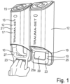
- Figure 1 shows an emergency aid material unit 10 which is accommodated in a dispenser 12.
- a dispenser 12 which is accommodated in a dispenser 12.
- Emergency aid material unit 10 is provided.
- the dispenser is marked with the inscription "Traumaset” or similar, which is provided with the reference number 13, in order to draw attention to the contents.
- the internationally customary sign of the cross is applied to the dispenser (reference number 15), which indicates materials for emergency aid.
- the dispenser 12 comprises a housing 17 and a housing opening 19, wherein the housing opening 19 is formed, among other things, by the fact that the front side 21, which faces the user during use, is shortened in the longitudinal direction of the dispenser 12, so that a handle element 23 of the emergency aid material unit 10 protrudes downwards from the housing 17 in the figurative representation.
- the handle element 23 is designed like a bracket 25 and can in particular be marked in color or also reinforced in order to ensure easy recognition and to make the function clear and recognizable.
- the bow-like handle element 23 is designed in such a way that the two side parts 25a and 25b are each hinged to a receiving compartment 27 of the emergency aid material unit 10, thus forming an opening 29 between the handle element 23 and the receiving compartment 27, into which the fingers of a hand can engage, as shown in the illustration for the left dispenser 12, and in the present arrangement the emergency aid material unit 10 can be moved in the direction of can be pulled out from the dispenser 12 at the bottom.
- the emergency aid material unit 10 comprises Figure 1 two film sections which, when placed on top of one another, form two receiving spaces 35 of two receiving compartments 31, 33 by welding, whereby the receiving compartments in the present case are connected via film hinges.
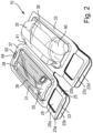
- the emergency aid material unit 10 is in Figure 2 shown in the state taken out of the dispenser, with two receiving compartments 31 and 33 being provided, each designed to form a receiving space 35 for the emergency aid material, with the receiving space 35 being sealed on all sides by thermal or ultrasonic welding or other known measures and enclosing the emergency aid material.
- the peripheral seam is provided with the reference number 37.
- the receiving compartments 31 and 33 are designed as film packaging and can be evacuated and sterilized if necessary.
- the handle elements 23 are also formed by the film layers, with reinforcing elements being able to be applied in the area of the handle elements 23 and areas of the film layers being able to be punched out to form a handle opening 29.
- Each handle element 23 consists of two layers 23a and 23b, which are arranged flatly one above the other and thus form the handle element 23. Due to the provision of two receiving compartments 31, 33, this results in a total of four handle layers 23a, b, c, d, which, when the emergency aid material unit 10 is received in the dispenser 12, all arranged one above the other and form a common handle element 23. As a result, the handle element 23 has sufficient robustness to enable the emergency aid material unit 10 to be removed from the dispenser 12 without the emergency aid material unit 10 being accidentally destroyed even when a certain amount of force is applied.
- Plastic trays 38 are accommodated in each of the receiving compartments 35, in which the emergency aid material is presented and arranged.
- bandage material 39 for applying a pressure bandage is provided in one of the receiving compartments 31 and a binding device 40 is provided in the second receiving compartment 33.
- the materials provided in the receiving compartments 31 and 33 can be marked accordingly by applying a lettering so that a user immediately knows what is provided in which compartment 31, 33.
- a film hinge 41 is formed between the receiving compartments 31 and 33, which enables an articulated connection of the two receiving compartments 31, 33, so that the two receiving compartments 31 and 33, when received in the dispenser 12, can be placed on top of one another with the back of their plastic shells 38, so that the four handle layers 23a, 23b, 23c and 23d complement each other to form a single handle element 23.
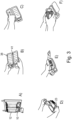
- Figure 3 shows the application of an emergency aid material unit 10 according to the invention.
- Figure 3 shows in figures A), B), C), D), E) to F).
- Figure A) the Removal of the emergency aid material unit 10 from the dispenser 12 according to Figure 1 .
- the emergency aid material units 10 are held in the dispenser 12 in such a way that they are secured against accidental removal or falling out, but at the same time easy removal is possible.
- the film hinge 41 is pivoted in such a way that the backs of the plastic shells 38 face the user.
- Instructions for use are provided on the backs of the plastic shells 38. These can be printed on the film material or, if provided, on the plastic shells, or can be enclosed loosely, which is shown in the Figures 3B and C
- the receiving compartments 31, 33 are now opened by holding one of the layers 23a of a handle element 23 and pulling the other layer in the opposite direction in the manner of a peeling movement, so that the peripheral seam 37 is either destroyed or the film material within the peripheral seam is destroyed, so that the emergency aid material provided in the receiving space 35, as shown in Figure 3E ) shown.
- the handle element 23 serves as an opening aid. The emergency aid material is then available for emergency aid.
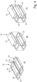
- FIG 4 shows a design in which Figure 4A ) an emergency aid material unit 10 as described in Figure 2 shown.
- the emergency aid material unit 10 is provided here in the form of two blister packs, wherein a shell element 43 is provided for each receiving compartment 31 and 33 and the shell element is covered and closed by a cover element 45.
- the handle element 23 is not designed in two layers.
- the cover element 45 is designed such that it extends over both shell elements 43 and forms the handle elements 23 by the cover element 45 extending over the shell element 43 in such a way that a bow-like handle element 23 is formed by making a cutout 29.
- a film hinge 41 is then provided, which enables the two receiving compartments to be folded onto one another.
- Figure 4B now shows an alternative design in which the two blister packs that form the receiving compartments 31, 33 are not integrally connected to one another via a film hinge, but are separated from one another and are fixed to one another in another way, for example via magnets, or alternatively via adhesive or welding points, whereby the fixation should be such that it can be released without great effort after the emergency aid material unit 10 has been removed from a dispenser 12.
- the cohesion should be so secure that, if used with a
- Dispenser 12 is provided, the two receiving compartments 31 and 33 do not separate from each other unintentionally.
- FIG 4C finally shows a design in which an extension compartment 47 is provided between the receiving compartments 31 and 33, which in turn are held together with magnets, which comes to lie between the cover elements 45 of the receiving compartments 31, 33, so that the handle elements 23 of the two receiving compartments 31 and 33 are spaced from one another by the thickness of the extension compartment 47.
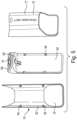
- FIG. 5 now shows the dispenser 12 on the right in the drawing in the assembled and mounted state, as well as on the left in the drawing in the opened state.
- the dispenser comprises a rear wall 50 and a cover 52, which together form the dispenser housing 17.
- the connection between the rear wall 50 and the cover 52 is made via locking elements 56, which are provided in both the cover 52 and the rear wall 52.
- the rear wall 50 also has a cover element 58 on which the previously described cross symbol 15 is arranged to identify the emergency aid material unit 10.
- the rear wall 50 is visible in the area of the housing opening 19 in the assembled state.
- a holding device 60 is provided, which has a fastening opening 62, which in Figure 2 shown in the The fastening opening 62 is preferably provided on the side of the emergency aid material unit facing away from the handle element 23.
- the removal of the emergency aid material unit 10 from the dispenser 12 takes place by destroying a material bridge 64 (see Figure 2 ), which tears when the emergency aid material unit is pulled out downwards.
- appropriate material weakenings can be provided in order to adjust the desired removal force.
- the housing is separated into its components, rear wall 50 and cover 52, so that the fastening opening 62 of the emergency aid material unit 10 can then be suspended via the holding element 60 and the cover is then attached to the rear wall 50, so that then, as in Figure 1 shown, the handle element 23 of the emergency aid material unit 10 is visible in the area of the housing opening 19.
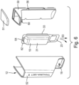
- FIG 6 shows a design in which the dispenser with the emergency aid material unit arranged therein is shown in an exploded view.
- the dispenser 12 consists of the cover 52 and the rear wall 50, with a lid element 51 being provided as part of the rear wall.
- the cover 52 and rear wall 50 are connected to one another via the locking elements 56, which are provided on both the cover ( Figure 5 ) and on the rear wall 50, are connected to one another in a detachable, snap-in manner.
- the emergency aid material unit 10 consists of the two receiving compartments 31 and 33 and has the handle element 23 protruding from the opening 19 of the dispenser.
- a fastening opening 62 is provided which engages over a corresponding holding element 60, whereby a material bridge 64 is destroyed when the emergency aid material unit 10 is pulled out in the direction of arrow 63, so that the emergency aid material unit 10 can be removed from the dispenser 12.
- Figure 7A shows an alternative design of a dispenser 80 with an additional protective element 81 in the closed state.
- the protective element 81 is pivotably connected to the housing rear wall 50 via a hinge-like connection 84.
- the protective element covers the handle element 23 in the manner of a covering means.
- the protective element 81 is flush with the outer edges of Housing rear panel 50 and housing cover 52 and thus completes the housing to form a closed design.
- Figure 7B shows the same alternative design of a dispenser 80 with an additional protective element 81 in the open state.
- the protective element 81 has a closure element 83 on its front edge 82 which ends with the housing cover 52, which is designed in such a way that it can be exposed on the inside of the front edge 84 of the housing cover 52, e.g. it can be held there with a force fit or a form fit.
- the protective element 81 is permanently connected to the housing rear wall 50 via a hinge-like connection 84.
- FIG 8 now shows an alternative design of a dispenser, which is provided here with the reference number 70.
- the dispenser 70 contains a housing 72 consisting of a cover element 74 and a frame element 76 as well as a rear wall 78, which are shown in an exploded view in Figure 6B.
- the handle elements 80 shown in Figures 6A and 6B are provided on the frame element, by means of which the dispenser 70 can be moved.
- the frame element 76 has subdivisions in the form of compartments, wherein a receiving compartment 31, 33 in the form of a blister pack, which is bone-shaped here, can be introduced into each compartment. If necessary, the individual receiving compartments 31, 33 can then be removed from the dispenser 70.
Landscapes
- Health & Medical Sciences (AREA)
- Engineering & Computer Science (AREA)
- Biomedical Technology (AREA)
- Heart & Thoracic Surgery (AREA)
- Vascular Medicine (AREA)
- Life Sciences & Earth Sciences (AREA)
- Animal Behavior & Ethology (AREA)
- General Health & Medical Sciences (AREA)
- Public Health (AREA)
- Veterinary Medicine (AREA)
- Epidemiology (AREA)
- Packages (AREA)
Claims (20)
- Unité de matériel de secours d'urgence (10), dans laquelle une unité de matériel de secours d'urgence (10) comprend un ensemble de plusieurs matériels de secours d'urgence qui sont confectionnés en commun, comprenant au moins un compartiment de réception (31, 33) pour recevoir du matériel de secours d'urgence, dans laquelle chaque compartiment de réception (31, 33) présente un espace de réception (35) fermé et apte à être ouvert qui est réalisé entre deux couches reliées le long d'une couture circonférentielle fermée (37), caractérisée par le fait qu'au moins deux compartiments de réception (31, 33) sont prévus, dans laquelle chacun des compartiments de réception (31, 33) présente au moins un élément de poignée (23) et dans laquelle ledit au moins un élément de poignée (23) est réalisé en forme d'étrier (25).
- Unité de matériel de secours d'urgence selon la revendication 1, caractérisée par le fait qu'au moins une, de préférence les deux couches du compartiment de réception (31, 33) est reliée à un élément de poignée (23).
- Unité de matériel de secours d'urgence selon la revendication 1 ou 2, caractérisée par le fait que ledit au moins un élément de poignée (23) est relié d'un seul tenant à la couche respective à l'extérieur de l'espace de réception (35).
- Unité de matériel de secours d'urgence selon l'une quelconque es revendications précédentes, caractérisée par le fait que ledit au moins un élément de poignée (23) s'étend à partir de la couture circonférentielle (37) en particulier dans le sens de la surface des couches.
- Unité de matériel de secours d'urgence selon l'une quelconque des revendications précédentes, caractérisée par le fait que ledit au moins un compartiment de réception (31, 33) est réalisé en tant qu'emballage en blister et qu'une des couches est réalisée en tant qu'élément de coque (43) et l'autre couche est réalisée comme élément de couvercle (45).
- Unité de matériel de secours d'urgence selon l'une quelconque des revendications précédentes, caractérisée par le fait que les couches sont constituées de film plastique, en particulier de polyamide, de polypropylène, de polyéthylène ou de polyéthylène téréphtalate.
- Unité de matériel de secours d'urgence selon l'une quelconque des revendications précédentes, caractérisée par le fait que lesdits au moins deux compartiments de réception (31, 33) sont reliés ou peuvent être reliés l'un à l'autre, de préférence peuvent être reliés de manière amovible.
- Unité de matériel de secours d'urgence selon l'une quelconque des revendications précédentes, caractérisée par le fait que les éléments de poignée (23) sont réalisés en particulier de manière à se chevaucher en surface.
- Unité de matériel de secours d'urgence selon l'une quelconque des revendications précédentes, caractérisée par le fait que les compartiments de réception (31, 33) et/ou les éléments de poignée (23) peuvent être disposés les uns au-dessus des autres dans la direction perpendiculaire à la direction de surface et se chevauchent, dans cette disposition, en termes de surface.
- Unité de matériel de secours d'urgence selon l'une quelconque des revendications précédentes, caractérisée par le fait que les compartiments de réception (31, 33) sont reliés entre eux par l'intermédiaire d'une charnière film (41), en particulier sur un bord latéral ne présentant pas l'élément de poignée (23), dans laquelle des points destinés à la rupture, en particulier sous forme de perforations, sont prévus en particulier le long de la charnière film (41).
- Unité de matériel de secours d'urgence selon l'une quelconque des revendications précédentes, caractérisée par le fait que les compartiments de réception (31, 33) peuvent être reliés entre eux de manière amovible par l'intermédiaire d'éléments magnétiques complémentaires.
- Unité de matériel de secours d'urgence selon l'une quelconque des revendications précédentes, caractérisée par le fait que l'un au moins des compartiments de réception (31, 33) présente une aide à l'ouverture.
- Unité de matériel de secours d'urgence selon l'une quelconque des revendications précédentes, caractérisée par le fait que l'élément de poignée (23) fait fonction d'aide à l'ouverture.
- Unité de matériel de secours d'urgence selon l'une quelconque des revendications précédentes, caractérisée par le fait qu'une ouverture de fixation est prévue, en particulier de manière opposée à l'élément de poignée (23) par rapport à l'espace de réception (35), qui est située à l'extérieur de l'espace de réception, pour la fixation à un dispositif de maintien.
- Distributeur d'unité de matériel de secours d'urgence, comprenant une unité de matériel de secours d'urgence (10), un boîtier (17) destiné à recevoir l'unité de matériel de secours d'urgence (10) ainsi qu'une ouverture de boîtier (19) à travers laquelle l'unité de matériel de secours d'urgence (10) peut être retirée, caractérisé par le fait que l'unité de matériel de secours d'urgence (10) comprend au moins un compartiment de réception (31, 33) destiné à recevoir du matériel de secours d'urgence, dans lequel chaque compartiment de réception (31, 33) présente un espace de réception (35) fermé et apte à être ouvert qui est réalisé entre deux couches reliées le long d'une couture circonférentielle fermée (37), et dans lequel un élément de poignée (23) est relié à au moins un compartiment de réception (31, 33) et l'unité de matériel de secours d'urgence présente les caractéristiques des revendications 1 à 14.
- Distributeur d'unité de matériel de secours d'urgence selon la revendication 15, caractérisé par le fait que le boîtier (17) et l'ouverture de boîtier (19) sont conçus de telle sorte que les éléments de poignée (23) s'étendent hors de l'ouverture de boîtier (15) lorsque l'unité de matériel de secours d'urgence (10) est logé dans le boîtier (17).
- Distributeur d'unité de matériel de secours d'urgence selon la revendication 15 ou 16, caractérisé par le fait que le boîtier (17) présente une paroi arrière (54) et une couverture (52) qui peuvent être reliés entre elles de manière amovible pour former le boîtier (17).
- Distributeur d'unité de matériel de secours d'urgence selon l'une quelconque des revendications précédentes 15 à 17, caractérisé par le fait que le boîtier présente un élément de protection (81) qui ferme ou réduit la taille de l'ouverture de boîtier (19) et dans lequel l'élément de protection (81) est maintenu sur le boîtier (17) en particulier de manière à pouvoir être pivoté.
- Distributeur d'unité de matériel de secours d'urgence selon l'une quelconque des revendications précédentes 15 à 18, caractérisé par le fait que le distributeur (12) présente un dispositif de maintien (60) dans le boîtier (17), qui traverse une ouverture de fixation (64) dans l'unité de matériel de secours d'urgence (10).
- Distributeur d'unité de matériel de secours d'urgence selon l'une quelconque des revendications précédentes 15 à 19, caractérisé par le fait que le distributeur d'unité de matériel de secours d'urgence (12) est équipé d'un dispositif de communication, en particulier d'un dispositif de signalisation optique ou acoustique, d'un dispositif caméra et/ou d'un codage.
Applications Claiming Priority (2)
| Application Number | Priority Date | Filing Date | Title |
|---|---|---|---|
| DE102018109741.7A DE102018109741A1 (de) | 2018-04-23 | 2018-04-23 | Nothilfematerialeinheit |
| PCT/EP2019/058894 WO2019206615A1 (fr) | 2018-04-23 | 2019-04-09 | Unité de matériel d'aide d'urgence |
Publications (2)
| Publication Number | Publication Date |
|---|---|
| EP3784191A1 EP3784191A1 (fr) | 2021-03-03 |
| EP3784191B1 true EP3784191B1 (fr) | 2025-02-12 |
Family
ID=66182517
Family Applications (1)
| Application Number | Title | Priority Date | Filing Date |
|---|---|---|---|
| EP19717805.6A Active EP3784191B1 (fr) | 2018-04-23 | 2019-04-09 | Unité de matériel d'aide d'urgence |
Country Status (3)
| Country | Link |
|---|---|
| EP (1) | EP3784191B1 (fr) |
| DE (1) | DE102018109741A1 (fr) |
| WO (1) | WO2019206615A1 (fr) |
Families Citing this family (1)
| Publication number | Priority date | Publication date | Assignee | Title |
|---|---|---|---|---|
| US11696859B2 (en) * | 2020-01-14 | 2023-07-11 | Joshua J. DeLisle | Wall-mounted medical kit |
Family Cites Families (15)
| Publication number | Priority date | Publication date | Assignee | Title |
|---|---|---|---|---|
| EP0354172A1 (fr) * | 1988-07-26 | 1990-02-07 | Demetrio Leone | Empaquetage d'objets absorbants en particulier de couches |
| US5108004A (en) * | 1990-09-10 | 1992-04-28 | Baldwin Gene R | Additional storage means for a covered receptacle |
| US5718245A (en) * | 1994-12-19 | 1998-02-17 | Horn; Rodney K. | First aid treatment incorporating universal precautions and containment of infectious body fluids |
| US6622856B2 (en) * | 2001-04-25 | 2003-09-23 | Johnson & Johnson Consumer Companies, Inc. | Relief kit |
| US7044329B2 (en) * | 2003-07-21 | 2006-05-16 | Simplehuamn Llc | Container for storing and dispensing bags |
| DE102005017945A1 (de) | 2005-04-18 | 2006-10-19 | Paul Hartmann Ag | Erste-Hilfe-Material-Einheit, Verfahren sowie Verbandsmaterialbehältnis |
| US7398883B2 (en) * | 2005-05-23 | 2008-07-15 | Tucker Kenneth H | Blister kit and method of using same |
| DE102005040398B4 (de) * | 2005-08-25 | 2008-05-29 | Wolfsburg Ag | Behälteranordnung |
| DE102005063227A1 (de) | 2005-12-23 | 2007-06-28 | Cmc Consumer Medical Care Gmbh | Nothilfematerial-Einheit |
| WO2009036746A2 (fr) * | 2007-09-17 | 2009-03-26 | Imeco Einwegprodukte Gmbh & Co. Kg | Dispositif de stockage et/ou de mise à disposition |
| DE202008008183U1 (de) | 2008-06-18 | 2008-09-04 | CTC Behördentraining GmbH | Release System für Tourniquets (Abbindesysteme) |
| US20140027480A1 (en) | 2012-07-25 | 2014-01-30 | Joshua Van Heusen | Tourniquet holsters |
| WO2014182372A1 (fr) | 2013-05-10 | 2014-11-13 | Tribalco, Llc | Kit de gestion de trauma ayant un étui à garrot externe |
| US20170065469A1 (en) * | 2015-09-08 | 2017-03-09 | Richard F. E. Newcombe | First aid inside assembly carrier system |
| ITUA20162027A1 (it) * | 2016-03-25 | 2017-09-25 | Aimo Boot Marco | Zaino professione, in particolare per missioni di soccorso tecnico e/o sanitario specialistico |
-
2018
- 2018-04-23 DE DE102018109741.7A patent/DE102018109741A1/de active Pending
-
2019
- 2019-04-09 WO PCT/EP2019/058894 patent/WO2019206615A1/fr not_active Ceased
- 2019-04-09 EP EP19717805.6A patent/EP3784191B1/fr active Active
Also Published As
| Publication number | Publication date |
|---|---|
| WO2019206615A1 (fr) | 2019-10-31 |
| DE102018109741A1 (de) | 2019-10-24 |
| EP3784191A1 (fr) | 2021-03-03 |
Similar Documents
| Publication | Publication Date | Title |
|---|---|---|
| EP1182942B1 (fr) | Gant | |
| EP2110095A1 (fr) | Sac, notamment pour la réception d'objets contaminés | |
| EP3784191B1 (fr) | Unité de matériel d'aide d'urgence | |
| EP3801092B1 (fr) | Blouse de chirurgien et kit de blouse de chirurgien | |
| DE3886940T2 (de) | Schutzvorrichtungen. | |
| EP0730853B2 (fr) | Trousse de premier secours | |
| CH631898A5 (en) | Sleeve for protecting a tubular apparatus, and a sterile packaging | |
| DE6923785U (de) | Sammelverpackung mit halteband | |
| EP1388325B1 (fr) | Sachet pour pansements | |
| DE102009022101A1 (de) | Verbandtasche | |
| DE202024100022U1 (de) | Rettungstasche zur Aufbewahrung und Bereitstellung von Medizinprodukten | |
| EP1535529B1 (fr) | Emballage combiné | |
| DE10040210A1 (de) | Handschuh | |
| AT383565B (de) | Folienverpackung fuer papiertaschentuecher | |
| DE202014008718U1 (de) | Kennzeichnungsband und Kennzeichnungssystem | |
| DE202006015407U1 (de) | Taschenkombination | |
| DE202010003880U1 (de) | Kennzeichnungssystem | |
| DE9213053U1 (de) | Kondome und Verpackungen für Kondome | |
| DE102005040424A1 (de) | Notfallversorgungsmittel und Behälteranordnung zur Lagerung solcher Notfallversorgungsmittel | |
| DE19528592A1 (de) | Unfall-Paß | |
| DE20208979U1 (de) | Tasche | |
| DE29512552U1 (de) | Unfall-Paß | |
| DE202010003881U1 (de) | Kennzeichnungssystem | |
| DE29502988U1 (de) | Trägerfolie | |
| DE202016103341U1 (de) | Verbandtasche |
Legal Events
| Date | Code | Title | Description |
|---|---|---|---|
| STAA | Information on the status of an ep patent application or granted ep patent |
Free format text: STATUS: UNKNOWN |
|
| STAA | Information on the status of an ep patent application or granted ep patent |
Free format text: STATUS: THE INTERNATIONAL PUBLICATION HAS BEEN MADE |
|
| PUAI | Public reference made under article 153(3) epc to a published international application that has entered the european phase |
Free format text: ORIGINAL CODE: 0009012 |
|
| STAA | Information on the status of an ep patent application or granted ep patent |
Free format text: STATUS: REQUEST FOR EXAMINATION WAS MADE |
|
| 17P | Request for examination filed |
Effective date: 20200922 |
|
| AK | Designated contracting states |
Kind code of ref document: A1 Designated state(s): AL AT BE BG CH CY CZ DE DK EE ES FI FR GB GR HR HU IE IS IT LI LT LU LV MC MK MT NL NO PL PT RO RS SE SI SK SM TR |
|
| AX | Request for extension of the european patent |
Extension state: BA ME |
|
| DAV | Request for validation of the european patent (deleted) | ||
| DAX | Request for extension of the european patent (deleted) | ||
| STAA | Information on the status of an ep patent application or granted ep patent |
Free format text: STATUS: EXAMINATION IS IN PROGRESS |
|
| 17Q | First examination report despatched |
Effective date: 20230519 |
|
| GRAP | Despatch of communication of intention to grant a patent |
Free format text: ORIGINAL CODE: EPIDOSNIGR1 |
|
| STAA | Information on the status of an ep patent application or granted ep patent |
Free format text: STATUS: GRANT OF PATENT IS INTENDED |
|
| RIC1 | Information provided on ipc code assigned before grant |
Ipc: A61B 50/31 20160101ALI20240726BHEP Ipc: A61B 50/30 20160101ALI20240726BHEP Ipc: A61B 50/00 20160101ALI20240726BHEP Ipc: B65D 83/00 20060101ALI20240726BHEP Ipc: A61F 17/00 20060101ALI20240726BHEP Ipc: A61F 15/00 20060101AFI20240726BHEP |
|
| INTG | Intention to grant announced |
Effective date: 20240809 |
|
| RIN1 | Information on inventor provided before grant (corrected) |
Inventor name: VOGT, RAINER Inventor name: GERBER, THOMAS Inventor name: BERNET, CLAUDIA Inventor name: ETTLIN, KARIN Inventor name: ROTHMAIER, MARKUS |
|
| GRAS | Grant fee paid |
Free format text: ORIGINAL CODE: EPIDOSNIGR3 |
|
| GRAA | (expected) grant |
Free format text: ORIGINAL CODE: 0009210 |
|
| STAA | Information on the status of an ep patent application or granted ep patent |
Free format text: STATUS: THE PATENT HAS BEEN GRANTED |
|
| RAP3 | Party data changed (applicant data changed or rights of an application transferred) |
Owner name: IVF HARTMANN AG |
|
| AK | Designated contracting states |
Kind code of ref document: B1 Designated state(s): AL AT BE BG CH CY CZ DE DK EE ES FI FR GB GR HR HU IE IS IT LI LT LU LV MC MK MT NL NO PL PT RO RS SE SI SK SM TR |
|
| REG | Reference to a national code |
Ref country code: GB Ref legal event code: FG4D Free format text: NOT ENGLISH |
|
| REG | Reference to a national code |
Ref country code: CH Ref legal event code: EP |
|
| REG | Reference to a national code |
Ref country code: DE Ref legal event code: R096 Ref document number: 502019012915 Country of ref document: DE |
|
| REG | Reference to a national code |
Ref country code: IE Ref legal event code: FG4D Free format text: LANGUAGE OF EP DOCUMENT: GERMAN |
|
| P01 | Opt-out of the competence of the unified patent court (upc) registered |
Free format text: CASE NUMBER: APP_7464/2025 Effective date: 20250213 |
|
| REG | Reference to a national code |
Ref country code: SE Ref legal event code: TRGR |
|
| REG | Reference to a national code |
Ref country code: NL Ref legal event code: MP Effective date: 20250212 |
|
| PG25 | Lapsed in a contracting state [announced via postgrant information from national office to epo] |
Ref country code: RS Free format text: LAPSE BECAUSE OF FAILURE TO SUBMIT A TRANSLATION OF THE DESCRIPTION OR TO PAY THE FEE WITHIN THE PRESCRIBED TIME-LIMIT Effective date: 20250512 |
|
| PG25 | Lapsed in a contracting state [announced via postgrant information from national office to epo] |
Ref country code: FI Free format text: LAPSE BECAUSE OF FAILURE TO SUBMIT A TRANSLATION OF THE DESCRIPTION OR TO PAY THE FEE WITHIN THE PRESCRIBED TIME-LIMIT Effective date: 20250212 |
|
| PG25 | Lapsed in a contracting state [announced via postgrant information from national office to epo] |
Ref country code: PL Free format text: LAPSE BECAUSE OF FAILURE TO SUBMIT A TRANSLATION OF THE DESCRIPTION OR TO PAY THE FEE WITHIN THE PRESCRIBED TIME-LIMIT Effective date: 20250212 |
|
| PGFP | Annual fee paid to national office [announced via postgrant information from national office to epo] |
Ref country code: DE Payment date: 20250417 Year of fee payment: 7 |
|
| PG25 | Lapsed in a contracting state [announced via postgrant information from national office to epo] |
Ref country code: ES Free format text: LAPSE BECAUSE OF FAILURE TO SUBMIT A TRANSLATION OF THE DESCRIPTION OR TO PAY THE FEE WITHIN THE PRESCRIBED TIME-LIMIT Effective date: 20250212 |
|
| REG | Reference to a national code |
Ref country code: LT Ref legal event code: MG9D |
|
| PG25 | Lapsed in a contracting state [announced via postgrant information from national office to epo] |
Ref country code: IS Free format text: LAPSE BECAUSE OF FAILURE TO SUBMIT A TRANSLATION OF THE DESCRIPTION OR TO PAY THE FEE WITHIN THE PRESCRIBED TIME-LIMIT Effective date: 20250612 Ref country code: NO Free format text: LAPSE BECAUSE OF FAILURE TO SUBMIT A TRANSLATION OF THE DESCRIPTION OR TO PAY THE FEE WITHIN THE PRESCRIBED TIME-LIMIT Effective date: 20250512 |
|
| PG25 | Lapsed in a contracting state [announced via postgrant information from national office to epo] |
Ref country code: NL Free format text: LAPSE BECAUSE OF FAILURE TO SUBMIT A TRANSLATION OF THE DESCRIPTION OR TO PAY THE FEE WITHIN THE PRESCRIBED TIME-LIMIT Effective date: 20250212 |
|
| PGFP | Annual fee paid to national office [announced via postgrant information from national office to epo] |
Ref country code: IT Payment date: 20250605 Year of fee payment: 7 |
|
| PG25 | Lapsed in a contracting state [announced via postgrant information from national office to epo] |
Ref country code: HR Free format text: LAPSE BECAUSE OF FAILURE TO SUBMIT A TRANSLATION OF THE DESCRIPTION OR TO PAY THE FEE WITHIN THE PRESCRIBED TIME-LIMIT Effective date: 20250212 |
|
| PG25 | Lapsed in a contracting state [announced via postgrant information from national office to epo] |
Ref country code: LV Free format text: LAPSE BECAUSE OF FAILURE TO SUBMIT A TRANSLATION OF THE DESCRIPTION OR TO PAY THE FEE WITHIN THE PRESCRIBED TIME-LIMIT Effective date: 20250212 Ref country code: PT Free format text: LAPSE BECAUSE OF FAILURE TO SUBMIT A TRANSLATION OF THE DESCRIPTION OR TO PAY THE FEE WITHIN THE PRESCRIBED TIME-LIMIT Effective date: 20250612 |
|
| PGFP | Annual fee paid to national office [announced via postgrant information from national office to epo] |
Ref country code: FR Payment date: 20250422 Year of fee payment: 7 |
|
| PG25 | Lapsed in a contracting state [announced via postgrant information from national office to epo] |
Ref country code: BG Free format text: LAPSE BECAUSE OF FAILURE TO SUBMIT A TRANSLATION OF THE DESCRIPTION OR TO PAY THE FEE WITHIN THE PRESCRIBED TIME-LIMIT Effective date: 20250212 Ref country code: GR Free format text: LAPSE BECAUSE OF FAILURE TO SUBMIT A TRANSLATION OF THE DESCRIPTION OR TO PAY THE FEE WITHIN THE PRESCRIBED TIME-LIMIT Effective date: 20250513 |
|
| PGFP | Annual fee paid to national office [announced via postgrant information from national office to epo] |
Ref country code: CH Payment date: 20250505 Year of fee payment: 7 |
|
| PGFP | Annual fee paid to national office [announced via postgrant information from national office to epo] |
Ref country code: AT Payment date: 20250507 Year of fee payment: 7 |
|
| PGFP | Annual fee paid to national office [announced via postgrant information from national office to epo] |
Ref country code: SE Payment date: 20250423 Year of fee payment: 7 |
|
| PG25 | Lapsed in a contracting state [announced via postgrant information from national office to epo] |
Ref country code: SM Free format text: LAPSE BECAUSE OF FAILURE TO SUBMIT A TRANSLATION OF THE DESCRIPTION OR TO PAY THE FEE WITHIN THE PRESCRIBED TIME-LIMIT Effective date: 20250212 |
|
| PG25 | Lapsed in a contracting state [announced via postgrant information from national office to epo] |
Ref country code: DK Free format text: LAPSE BECAUSE OF FAILURE TO SUBMIT A TRANSLATION OF THE DESCRIPTION OR TO PAY THE FEE WITHIN THE PRESCRIBED TIME-LIMIT Effective date: 20250212 |
|
| PG25 | Lapsed in a contracting state [announced via postgrant information from national office to epo] |
Ref country code: CZ Free format text: LAPSE BECAUSE OF FAILURE TO SUBMIT A TRANSLATION OF THE DESCRIPTION OR TO PAY THE FEE WITHIN THE PRESCRIBED TIME-LIMIT Effective date: 20250212 Ref country code: EE Free format text: LAPSE BECAUSE OF FAILURE TO SUBMIT A TRANSLATION OF THE DESCRIPTION OR TO PAY THE FEE WITHIN THE PRESCRIBED TIME-LIMIT Effective date: 20250212 |
|
| PG25 | Lapsed in a contracting state [announced via postgrant information from national office to epo] |
Ref country code: RO Free format text: LAPSE BECAUSE OF FAILURE TO SUBMIT A TRANSLATION OF THE DESCRIPTION OR TO PAY THE FEE WITHIN THE PRESCRIBED TIME-LIMIT Effective date: 20250212 |
|
| PG25 | Lapsed in a contracting state [announced via postgrant information from national office to epo] |
Ref country code: SK Free format text: LAPSE BECAUSE OF FAILURE TO SUBMIT A TRANSLATION OF THE DESCRIPTION OR TO PAY THE FEE WITHIN THE PRESCRIBED TIME-LIMIT Effective date: 20250212 |
|
| REG | Reference to a national code |
Ref country code: DE Ref legal event code: R097 Ref document number: 502019012915 Country of ref document: DE |
|
| PG25 | Lapsed in a contracting state [announced via postgrant information from national office to epo] |
Ref country code: LU Free format text: LAPSE BECAUSE OF NON-PAYMENT OF DUE FEES Effective date: 20250409 |
|
| PLBE | No opposition filed within time limit |
Free format text: ORIGINAL CODE: 0009261 |
|
| STAA | Information on the status of an ep patent application or granted ep patent |
Free format text: STATUS: NO OPPOSITION FILED WITHIN TIME LIMIT |
|
| PG25 | Lapsed in a contracting state [announced via postgrant information from national office to epo] |
Ref country code: MC Free format text: LAPSE BECAUSE OF FAILURE TO SUBMIT A TRANSLATION OF THE DESCRIPTION OR TO PAY THE FEE WITHIN THE PRESCRIBED TIME-LIMIT Effective date: 20250212 |
|
| REG | Reference to a national code |
Ref country code: BE Ref legal event code: MM Effective date: 20250430 |
|
| PG25 | Lapsed in a contracting state [announced via postgrant information from national office to epo] |
Ref country code: BE Free format text: LAPSE BECAUSE OF NON-PAYMENT OF DUE FEES Effective date: 20250430 |
|
| 26N | No opposition filed |
Effective date: 20251113 |
|
| PGFP | Annual fee paid to national office [announced via postgrant information from national office to epo] |
Ref country code: GB Payment date: 20260324 Year of fee payment: 8 |
|
| PG25 | Lapsed in a contracting state [announced via postgrant information from national office to epo] |
Ref country code: IE Free format text: LAPSE BECAUSE OF NON-PAYMENT OF DUE FEES Effective date: 20250409 |