EP3784373B1 - Procédé et réacteur oxidatif de traitement d'une liqueur usée contenant du sulfure - Google Patents
Procédé et réacteur oxidatif de traitement d'une liqueur usée contenant du sulfure Download PDFInfo
- Publication number
- EP3784373B1 EP3784373B1 EP19719330.3A EP19719330A EP3784373B1 EP 3784373 B1 EP3784373 B1 EP 3784373B1 EP 19719330 A EP19719330 A EP 19719330A EP 3784373 B1 EP3784373 B1 EP 3784373B1
- Authority
- EP
- European Patent Office
- Prior art keywords
- steam
- oxidation reactor
- chamber
- oxygen
- temperature
- Prior art date
- Legal status (The legal status is an assumption and is not a legal conclusion. Google has not performed a legal analysis and makes no representation as to the accuracy of the status listed.)
- Active
Links
Images

Classifications
-
- C—CHEMISTRY; METALLURGY
- C02—TREATMENT OF WATER, WASTE WATER, SEWAGE, OR SLUDGE
- C02F—TREATMENT OF WATER, WASTE WATER, SEWAGE, OR SLUDGE
- C02F11/00—Treatment of sludge; Devices therefor
- C02F11/06—Treatment of sludge; Devices therefor by oxidation
- C02F11/08—Wet air oxidation
-
- C—CHEMISTRY; METALLURGY
- C02—TREATMENT OF WATER, WASTE WATER, SEWAGE, OR SLUDGE
- C02F—TREATMENT OF WATER, WASTE WATER, SEWAGE, OR SLUDGE
- C02F1/00—Treatment of water, waste water, or sewage
- C02F1/72—Treatment of water, waste water, or sewage by oxidation
- C02F1/727—Treatment of water, waste water, or sewage by oxidation using pure oxygen or oxygen rich gas
-
- B—PERFORMING OPERATIONS; TRANSPORTING
- B01—PHYSICAL OR CHEMICAL PROCESSES OR APPARATUS IN GENERAL
- B01J—CHEMICAL OR PHYSICAL PROCESSES, e.g. CATALYSIS OR COLLOID CHEMISTRY; THEIR RELEVANT APPARATUS
- B01J19/00—Chemical, physical or physico-chemical processes in general; Their relevant apparatus
- B01J19/0006—Controlling or regulating processes
- B01J19/0013—Controlling the temperature of the process
-
- C—CHEMISTRY; METALLURGY
- C02—TREATMENT OF WATER, WASTE WATER, SEWAGE, OR SLUDGE
- C02F—TREATMENT OF WATER, WASTE WATER, SEWAGE, OR SLUDGE
- C02F1/00—Treatment of water, waste water, or sewage
- C02F1/72—Treatment of water, waste water, or sewage by oxidation
-
- B—PERFORMING OPERATIONS; TRANSPORTING
- B01—PHYSICAL OR CHEMICAL PROCESSES OR APPARATUS IN GENERAL
- B01J—CHEMICAL OR PHYSICAL PROCESSES, e.g. CATALYSIS OR COLLOID CHEMISTRY; THEIR RELEVANT APPARATUS
- B01J2219/00—Chemical, physical or physico-chemical processes in general; Their relevant apparatus
- B01J2219/00049—Controlling or regulating processes
- B01J2219/00051—Controlling the temperature
- B01J2219/00121—Controlling the temperature by direct heating or cooling
-
- B—PERFORMING OPERATIONS; TRANSPORTING
- B01—PHYSICAL OR CHEMICAL PROCESSES OR APPARATUS IN GENERAL
- B01J—CHEMICAL OR PHYSICAL PROCESSES, e.g. CATALYSIS OR COLLOID CHEMISTRY; THEIR RELEVANT APPARATUS
- B01J2219/00—Chemical, physical or physico-chemical processes in general; Their relevant apparatus
- B01J2219/00761—Details of the reactor
- B01J2219/00763—Baffles
- B01J2219/00765—Baffles attached to the reactor wall
- B01J2219/00777—Baffles attached to the reactor wall horizontal
-
- B—PERFORMING OPERATIONS; TRANSPORTING
- B01—PHYSICAL OR CHEMICAL PROCESSES OR APPARATUS IN GENERAL
- B01J—CHEMICAL OR PHYSICAL PROCESSES, e.g. CATALYSIS OR COLLOID CHEMISTRY; THEIR RELEVANT APPARATUS
- B01J2219/00—Chemical, physical or physico-chemical processes in general; Their relevant apparatus
- B01J2219/18—Details relating to the spatial orientation of the reactor
- B01J2219/185—Details relating to the spatial orientation of the reactor vertical
-
- C—CHEMISTRY; METALLURGY
- C02—TREATMENT OF WATER, WASTE WATER, SEWAGE, OR SLUDGE
- C02F—TREATMENT OF WATER, WASTE WATER, SEWAGE, OR SLUDGE
- C02F2101/00—Nature of the contaminant
- C02F2101/10—Inorganic compounds
- C02F2101/101—Sulfur compounds
-
- C—CHEMISTRY; METALLURGY
- C02—TREATMENT OF WATER, WASTE WATER, SEWAGE, OR SLUDGE
- C02F—TREATMENT OF WATER, WASTE WATER, SEWAGE, OR SLUDGE
- C02F2103/00—Nature of the water, waste water, sewage or sludge to be treated
- C02F2103/18—Nature of the water, waste water, sewage or sludge to be treated from the purification of gaseous effluents
-
- C—CHEMISTRY; METALLURGY
- C02—TREATMENT OF WATER, WASTE WATER, SEWAGE, OR SLUDGE
- C02F—TREATMENT OF WATER, WASTE WATER, SEWAGE, OR SLUDGE
- C02F2209/00—Controlling or monitoring parameters in water treatment
- C02F2209/02—Temperature
-
- C—CHEMISTRY; METALLURGY
- C02—TREATMENT OF WATER, WASTE WATER, SEWAGE, OR SLUDGE
- C02F—TREATMENT OF WATER, WASTE WATER, SEWAGE, OR SLUDGE
- C02F2305/00—Use of specific compounds during water treatment
- C02F2305/02—Specific form of oxidant
Definitions
- the invention relates to a method for treating a spent caustic from a caustic wash using an oxidation reactor and a corresponding plant and a corresponding oxidation reactor according to the respective preambles of the independent patent claims.
- Olefins such as ethylene or propylene, but also diolefins such as butadiene and aromatics can be produced from paraffins by steam cracking.
- Corresponding methods have been known for a long time. For details, refer to specialist literature such as the article " Ethylene” in Ullmann's Encyclopedia of Industrial Chemistry, online edition, April 15, 2007, DOI 10.1002/14356007.a10_045.pub2 , referenced.
- Corresponding processing includes, in particular, so-called acid gas removal, in which components such as carbon dioxide, hydrogen sulfide and mercaptans are separated from the cracked gas.
- the cracked gas is typically compressed before and after an appropriate treatment.
- the cracked gas can be taken from a so-called raw gas compressor at an intermediate pressure level, subjected to acid gas removal and then further compressed in the raw gas compressor.
- the acid gas removal can in particular include a so-called caustic scrubbing using caustic soda.
- the caustic wash can also be combined with an amine wash, for example using ethanolamine.
- the spent liquor obtained in the caustic wash which contains a few percent of sulfide and carbonate, is typically oxidized in a spent caustic treatment and, if necessary, neutralized before it can be subjected to a biological wastewater treatment.
- the oxidation serves to remove toxic components and to reduce the biological oxygen demand.
- the spent liquor oxidation is typically carried out in the form of a wet chemical oxidation of the sulphide with oxygen in solution.
- the spent liquor can be brought to the desired reaction pressure and heated in countercurrent with the oxidized spent liquor.
- the heated spent caustic liquor can then be fed into an oxidation reactor and oxidized with the supply of oxygen.
- the oxygen required for the reaction is added either in the form of air or as pure oxygen.
- An additional, in other process variants also the exclusive, heating of the spent caustic can be carried out by introducing hot steam into the oxidation reactor.
- the oxidized waste caustic is cooled down with the associated waste gas via a heat exchanger while heating the spent caustic. After a pressure check, the exhaust gas is separated from the liquid in a subsequent separator tank. The liquid, oxidized waste caustic can then be fed into a process for biological waste water treatment, with optional adjustment of the pH value (neutralization).
- the state of the art in waste caustic oxidation is an operating pressure of 6 to 40 bar and an operating temperature of up to over 200 °C, for example up to 210 °C.
- the residence time in the reactor required for substantial conversion falls from about 12 hours at 6 bar to 10% of the stated residence time at 30 bar.
- the spent caustic is fed into the oxidation reactor.
- An oxygen carrier usually air, is mixed with the lye at any point, usually before the actual reactor.
- the spent caustic or the spent caustic-oxygen carrier mixture can be preheated in a heat exchanger.
- the spent caustic can thus be fed into the oxidation reactor preheated.
- this is not mandatory. Further heating (or the only heating) often takes place by means of steam addition, which can take place either in the inflowing waste liquor or directly in the reactor, and generally also by the reaction enthalpy or exothermicity of the oxidation reactions.
- the waste caustic to the reactor can also be preheated against the product from the reactor in corresponding processes.
- an oxidation reactor used for the oxidation of waste caustic is constructed in such a way that a directed flow is formed in the reactor and a greater reaction rate and higher conversion are thereby possible.
- fixtures in the form of perforated floors can be used.
- Methods of the type explained above are, for example, from DE 10 2010 049 445 A1 , At which a pressure of more than 60 bar is used in a corresponding reaction reactor, and from the DE 10 2006 030 855 A1 known.
- reactors for the oxidation of waste caustic are made of high-quality materials such as nickel-based alloys or nickel.
- high-quality materials such as nickel-based alloys or nickel.
- such materials can also be attacked by high sulfide concentrations at elevated temperatures.
- the aforesaid addition of steam to the oxidation reactor is typically via one or more nozzles or lance constructions.
- the vapor should be distributed as uniformly as possible over the surface of the reactor, since, as mentioned, the flow through the oxidation reactor is typically in one direction and cross-mixing is thereby limited.
- a corresponding addition of steam cannot be controlled in conventional processes and plants, or can only be controlled to a small extent.
- sludge is heated by heating with previously treated sludge and fed to a steam-charged oxidizing chamber of a reactor divided into the oxidizing chamber and a heat-concentrating chamber.
- WO 2011/002138 A1 disclosed is a method of treating caustic soda comprising neutralizing caustic soda produced by an oil refining process using sulfuric acid and subjecting the neutralized caustic soda to wet air oxidation.
- the object of the present invention is to specify a process for the wet oxidation of a spent liquor that makes it possible to achieve optimum oxidation of the sulfur components of the spent liquor, particularly at an operating pressure of 20 to 40 bar and with a minimum residence time. At the same time, the process should be controllable over a wider operating range, especially when using very different amounts of steam.
- the aim of the process is to reduce the peak operating temperature in order to minimize the corrosive attack on the reactor material, which is primarily dependent on the temperature.
- the object of the present invention is also to provide a system that can be operated accordingly.
- the present invention proposes a method for treating a spent caustic from a caustic wash using an oxidation reactor and a corresponding plant and a corresponding oxidation reactor with the features of the respective independent patent claims. Configurations are the subject of the dependent patent claims and the following description.
- the present invention is based on the finding that the problems explained above can be overcome in the manner indicated by using an oxidation reactor configured as explained in detail below.
- the present invention proposes a method for treating a sulfide-containing spent caustic from a caustic scrubber, in which the spent caustic and oxygen or the spent caustic and an oxygen-containing gas mixture, for example air, are fed to an oxidation reactor and subjected to wet oxidation therein. Steam is fed into the oxidation reactor.
- the spent caustic and oxygen or the spent caustic and an oxygen-containing gas mixture for example air
- an oxidation reactor with a number of chambers is used, of which a first chamber has a larger volume than a second chamber.
- the spent caustic and the oxygen or the spent caustic and the oxygen-containing gas mixture are supplied to the first chamber. Fluid flowing out of the first chamber is transferred to the second chamber.
- a steam quantity and/or a steam temperature of the steam fed into the oxidation reactor is regulated with a control device, and the steam fed into the oxidation reactor is fed at least partially, in particular completely, into the first chamber and into the second chamber in the context of the present invention.
- the number of chambers used in the oxidation reactor used according to the invention is not limited. However, at least four chambers are typically provided, including the first and second chambers mentioned.
- the chambers are preferably arranged in series one behind the other in a corresponding oxidation reactor.
- a corresponding oxidation reactor is typically arranged in an upright position, with the chambers mentioned lying one above the other. Fluid typically flows through the oxidation reactor from bottom to top, the first chamber mentioned being the lowest chamber and the second chamber mentioned being the chamber which follows the lowest chamber and is arranged above the lowest chamber.
- the chambers mentioned are typically separated from one another by means of suitable separating devices, for example by sieve trays or by trays with nozzle valves to reduce backflow and thus backmixing. separated from each other.
- suitable separating devices for example by sieve trays or by trays with nozzle valves to reduce backflow and thus backmixing. separated from each other.
- the steam is fed in in the manner explained below, i.e. in particular using specially designed steam feed devices which allow a wide variation in the amounts of steam fed in.
- the invention comprises that the steam fed into the oxidation reactor is fed at least partially into the first chamber and into the second chamber.
- the steam is fed in advantageously in parallel into the first and the second chamber.
- a "parallel" feed does not necessarily include the feeding of the same, but in each case certain, amounts of steam into the first and into the second chamber.
- the present invention comprises the use of an entry chamber, the first chamber mentioned, and a second chamber arranged downstream thereof in a corresponding reactor.
- the chamber close to the inlet, ie the first chamber, and the following chamber, ie the second chamber, are provided with a steam lance or another steam feed device.
- the (first) chamber near the entry is enlarged in the context of the present invention compared to the (second) chamber following it, and in particular compared to all other chambers of the oxidation reactor, as a result of which comparatively high conversions can be achieved in this chamber.
- the volume of the first chamber is in particular 1.1 times, 1.5 times, 2 times, 3 times or more than 3 times the volume of the second chamber. In this way, the occurrence of high reactant concentrations near the inlet can be prevented by using the oxidation reactor designed according to the invention. In other words, a concentration of the sulfide, which is introduced into the oxidation reactor via the waste caustic, is reduced in the large first chamber near the inlet. In other words, a dilution takes place in the first chamber.
- the lower sulphide concentration in this chamber has the advantage over the high concentration in the spent liquor fed in that there is less corrosive attack on the reactor material. This leads to a reduction in the corrosive attack on the reactor material, particularly in connection with the aforementioned control of the steam quantity and/or steam temperature of the steam fed into the oxidation reactor.
- the oxidation reactor is advantageously fed saturated steam or steam superheated by at most 5 to 10°C.
- the steam temperature of the steam fed into the oxidation reactor is advantageously adjusted by mixing water into the heated steam.
- a device is advantageously used which uses superheated steam on the one hand and water on the other hand be supplied.
- a so-called desuperheater and a subsequent mixer can be used here in particular.
- the regulation is advantageously carried out in such a way that the steam quantity and/or the steam temperature of the steam fed into the oxidation reactor is based on a temperature recorded in the first chamber and/or the second chamber and on the basis of a recorded temperature of one from the reactor outflowing fluid is regulated.
- the temperature control advantageously includes measuring the temperature of the chambers of the oxidation reactor that are each equipped with steam feed devices. On this basis, the amounts of steam supplied is or are regulated. At the same time, an exit temperature from the oxidation reactor is set or recorded.
- a control cascade is used that includes the temperature of the lowest chamber, ie the first chamber mentioned, being set to a desired value.
- a maximum temperature is specified, which cannot and must not be exceeded in this first chamber.
- the setpoint value used for the temperature in the first chamber is specified within the scope of the regulation proposed according to the invention on the basis of the outlet temperature, ie on the basis of the detected temperature of the fluid flowing out of the reactor.
- the temperature at the top of a corresponding oxidation reactor can be adjusted to the temperatures in the chambers mentioned.
- the temperature measured in the chambers limits the amount of steam fed into these chambers.
- the regulation proposed according to the invention includes specifying a temperature setpoint and a maximum temperature in the first chamber and/or the second chamber. Due to the requirement to reduce the temperature in the first chamber, ie the lowest chamber with the highest concentration of sulphide, the temperature in the second chamber would possibly drop to a lower value than desired. Therefore, the steam is also fed into the second chamber. In this way, it can be heated in a targeted manner and the reaction conditions in this second chamber can be set advantageously.
- the supply of steam is thus advantageously distributed over the two chambers or the steam supply devices provided there.
- the steam feed to both chambers is advantageously regulated separately.
- the first chamber and the second chamber are therefore advantageously each equipped with an independent temperature sensor and the regulation is carried out in mutually independent control circuits.
- the amount of steam that is fed into the lower chamber, ie the first chamber is regulated to the temperature of the temperature element in the lowermost, ie the first chamber.
- the control in the second chamber is cascaded, taking into account the temperature at the reactor outlet.
- the respective desired value is therefore advantageously specified on the basis of the temperature of the fluid flowing out of the reactor.
- the volume of the first chamber is advantageously greater than an average volume of all the chambers of the oxidation reactor, with the factors explained above applying in particular.
- the size of the first chamber can also be defined in relation to the total volume of the reactor.
- the volume of the first chamber is at least one third and at most two thirds of the total volume of all chambers.
- the chamber near the inlet is enlarged, while the other chambers are smaller than the first chamber.
- the smaller chambers, which are arranged downstream of the second chamber in particular, have the task of reducing the residence time distribution in order to optimize overall conversion in the oxidation reactor.
- the amount of steam fed into the oxidation reactor can advantageously be regulated in a range from 5 to 100%. This means that a quantity of steam fed in at a first point in time can correspond to 5% to 100% of the quantity of steam fed in at a second point in time, or a corresponding desired value is specified by means of the control.
- the steam is advantageously at least partially introduced into the oxidation reactor by means of a steam feed device which has one or more cylindrical sections, each with a central axis and each with a wall, the central axis being or becoming perpendicular, in the wall a plurality of groups of Openings are formed, each of the groups includes a plurality of the openings, and the plurality of openings of each of the groups are arranged in one or more planes, each of which is or are oriented perpendicular to the central axis.
- the first and the second chamber can in particular each be provided with a corresponding steam feed device.
- Several cylindrical sections can be provided, particularly in larger reactors. For the sake of clarity, “one” cylindrical section is mentioned below, but the explanations also relate to the case that a plurality of cylindrical sections are provided.
- the lowest amount of steam fed in can be at least 40%, in real cases at least 60% of the normal load, but no less. This is due to the fact that steam hammers, for example due to local condensation and a faulty distribution of the steam, are to be expected if the flow to all lance holes is uneven.
- the steam feed mentioned above via the steam feed device just mentioned enables a particularly good controllability of the steam quantity fed in.
- steam is advantageously introduced into the reactor exclusively via the mentioned cylindrical section of one or more corresponding steam feed devices and thus into the waste liquor or into a two-phase mixture introduced from waste caustic and air.
- the cylindrical section can be designed as a "spigot" which is arranged vertically, in particular centrally, in a corresponding reactor.
- a corresponding oxidation reactor is typically at least partially cylindrical. In this case, in particular, the central axis of the cylindrical section of the steam feed device and a central axis of the oxidation reactor or its cylindrical section coincide.
- the cylindrical section Due to the fact that the cylindrical section is arranged vertically and several groups of openings are provided in it, which are arranged in several levels one above the other, condensate can accumulate in the cylindrical section due to condensation of the steam, which has a condensate level corresponding to the pressure conditions in the cylindrical Section can train.
- steam is condensed in the steam feed device or in its cylindrical section, with a condensate level forming in the cylindrical section which depends in particular on the pressure of the steam fed in.
- the cylindrical section becomes more and more full of condensate emptied and other openings, which are arranged in lower levels, are flowed through with steam until full load is reached.
- each of the groups comprises several of the openings and the several openings of each of the groups are arranged in one or more levels
- different groups can each have openings that are above and below a reference plane can be arranged. In this way, sufficient flow can be ensured even if a corresponding reactor is slightly inclined or if there is turbulence in the condensate level in the cylindrical section, in particular due to the steam being fed in.
- the several openings of each of the groups are arranged in one plane, several rows of holes are arranged one above the other, the openings of different rows of holes advantageously being spaced apart so that a particularly good mixing of the vapor can be ensured.
- the respective openings are distributed equidistantly around a circumference defined by a line of intersection of the respective plane with the wall.
- radial lines that emanate from the central axis in the corresponding plane and run through the respective openings enclose identical angles. In this way, a uniform mixing can be ensured, in particular in the case of a cylindrical design of the oxidation reactor.
- the openings of each of the groups are arranged in several planes and a maximum distance of the planes in which the openings of one of the groups lie is less than a minimum distance of the planes in which the openings of two different groups.
- the opening of each of the groups does not have to be in exactly one plane, but can also be arranged in different planes, which are however closer together than the planes of two different groups.
- two, three, four or more of the openings are arranged in each of the planes and, as mentioned, are equidistant along the wall around the circumference of the cylindrical section distributed. This results in intermediate angles between the openings of 180°, 120° or 90°.
- the number of openings per level can also be different. In particular, the number of openings can be minimized in a top level, so that the smallest possible underload operation can be ensured.
- the cylindrical portion of the steam injector has a first end and a second end and is terminated at the first end by an end face.
- the first end points downwards and ensures that the condensate can collect in the cylindrical section.
- at least one further opening can be formed in the closing surface, which ensures that condensate can drain out of the cylindrical section.
- Several openings can also be arranged in the end surface, the size and number of which can depend in particular on the amount of steam to be processed or fed in.
- the second end of the cylindrical section is connected to a steam supply line and/or support which extends from the second end of the cylindrical section to a wall of the oxidation reactor used.
- a steam feed line can be of cylindrical design and have the same or a different diameter than the cylindrical section of the steam feed device. To ensure ease of manufacture, the diameters are advantageously identical.
- the openings in the cylindrical section are arranged in such a way that steam flows out of them in an outflow direction that differs from a direction in which the steam supply line and/or the holders extend in a top view from the direction of the central axis.
- the openings are or are each arranged in such a way that steam escaping through them is advantageously not directed at the supply line and/or holder, in order to ensure that the outflow is as free as possible.
- the waste caustic and the oxygen or the oxygen-containing gas mixture are advantageously premixed before they are fed to the oxidation reactor.
- the spent caustic and the oxygen or that Oxygen-containing gas mixtures are advantageously fed to the oxidation reactor at ambient temperature and only heated up there. In this way, a temperature can be set and regulated precisely, particularly in the first chamber, in order to achieve the previously explained advantages of reduced corrosive attack on the reactor.
- the overall oxidation reactor is advantageously operated at a pressure level of 20 to 50 bar, in particular 30 to 40 bar, and at a temperature level of 150 to 220.degree. C., in particular 185 to 210.degree.
- the design of the oxidation reactor provided according to the invention reduces corrosive attacks.
- the present invention also extends to a plant for the treatment of a sulphide-containing waste liquor from a liquor wash, for the features of which reference is expressly made to the respective independent patent claim.
- the same also applies to the oxidation reactor proposed according to the invention.
- a system or a corresponding oxidation reactor is set up for carrying out a method as has been explained above in different configurations, and a corresponding system has correspondingly designed means for this purpose. Reference is therefore expressly made to the above explanations for corresponding features and advantages.
- figure 1 1 is a plant for the treatment of a waste caustic according to a particularly preferred embodiment of the invention and is denoted overall by 100 .
- Plant 100 illustrated is an oxidation reactor 10. In the example shown, this has a total of nine reactor chambers 11 to 19, but at least four reactor chambers.
- a chamber 11 arranged at the bottom near the inlet in the example shown and optionally the following chamber 12 are each provided with a steam feeder 21 and 22, for example a steam lance or a steam chamber protruding into the respective chamber 11, 12.
- the chamber 11 near the inlet is enlarged in comparison to the other chambers 12 to 19, with the aim of achieving relatively high conversions in this chamber and in this way preventing the occurrence of high educt concentrations near the inlet.
- the enlarged chamber 11 is larger than the average chamber volume and typically comprises more than one third of the total reactor volume and typically less than two thirds of it.
- the smaller chambers 12 to 19 above have the task of reducing the residence time distribution in order to optimize sales.
- the steam feeders 21, 22 are part of a steam system 20, which is based on a temperature sensor control TIC, to which several temperature sensors TI, which are arranged in the chambers 11 and 12 and at an outlet of the oxidation reactor 10, are connected.
- the TIC temperature sensor control regulates two Valves 23, 24, which are arranged upstream of a desuperheater or desuperheater 25, and by means of which an inflow of superheated steam 1 or boiler feed water 2 to the desuperheater 25 is adjusted. Fluid 3 flowing out of the desuperheater 25 is mixed in a mixer 26 and then distributed via valves 27 and 28 to the chambers 11, 12 and the steam feeders 21, 22, respectively.
- the large near entry chamber 21 results in a lower concentration of sulphide.
- the lower sulphide concentration in this chamber 21 in comparison to the high inlet concentration has the advantage that the corrosive attack on the reactor material, together with an operating temperature controlled by means of the steam system 20, is lower.
- the temperature is regulated by means of the steam system 20 by measuring the temperature of the chambers 11, 12, each equipped with steam feeders 21, 22, and regulates the quantity(s) of steam supplied. At the same time, an outlet temperature is set. Therefore a control cascade is used.
- the temperature at the top of the oxidation reactor 10 is compared with the temperatures in the chambers 11, 12 with the steam feeders 21, 22 and the measured temperature in the chambers 11, 12 with the steam feeders 21, 22 limits the amount of steam supplied.
- the temperature of the bottom chamber 11 is set to a target value by means of the temperature sensor control, whereby a maximum temperature must not be exceeded.
- the desired value is in turn set by a second controller, which controls the outlet temperature at the top of the oxidation reactor 10 .
- the oxidation reactor 10 is fed with a feed 4 which is typically two-phase and formed from liquor 5 taken from a tank 30 and from air 6 .
- the insert 4 is fed to the oxidation reactor 10 at ambient temperature and at 20 to 40 bar.
- a typically three-phase mixture of components 4 is removed from the oxidation reactor 10 .
- a flow of this mixture of components from the oxidation reactor 10 is adjusted by means of a valve 40, which is also operated with temperature control.
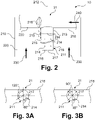
- FIG 2 12 is a highly simplified schematic of a portion of an oxidation reactor for use in a plant according to an embodiment of the present invention illustrated and overall as in figure 1 , labeled 10.
- the oxidation reactor 10 has a wall 210 which encloses an interior space 220 of the oxidation reactor 10 .
- a waste caustic or a mixture of waste caustic and air can be received in the interior space 220 and, for example, guided essentially in the direction of the arrows illustrated here in each case with 230 .
- the oxidation air and the spent liquor in particular can be heated before being fed into the oxidation reactor 10 . Additional heating can take place by means of a steam flow 240 which, as illustrated here, is introduced via a steam feed device 21 into the oxidation reactor 100 or into the spent liquor accommodated therein.
- the steam injection device 22, which is figure 1 is shown can be identical.
- the steam feed device 10 comprises a cylindrical section 211 which has a central axis 212 which, in particular, can correspond to a central axis of the oxidation reactor 10 as a whole.
- the cylindrical portion 211 includes a wall 213.
- the central axis 212 is oriented perpendicularly.
- a plurality of openings 214 are arranged in the wall 213, only some of which are provided with reference numbers.
- the openings 214 are arranged in a plurality of groups, with each of the groups including a plurality of the openings 214 and the plurality of openings of each of the groups being arranged in one or more planes, illustrated herein in phantom and labeled 215 .
- the planes 215 are each aligned perpendicularly to the central axis 212 .
- the central axis 212 intersects the planes 215 perpendicularly.
- several rows of openings 214 or rows of holes are formed within the scope of the present invention, which allow condensate to accumulate in the cylindrical section 211 and steam to flow only through the openings 14 that remain free into the interior 220 of the oxidation reactor 10 or in the waste caustic present there is introduced.
- a corresponding oxidation reactor 10 can be operated in an optimized manner, as explained several times above.
- the openings 214 are provided in the different levels 215 in the same or different numbers, with only a smaller number of openings being provided in particular in a level 215 shown here above can be to allow a minimum load.
- the distances I0 and I1 of the individual planes 214 from one another and in relation to the cylindrical section 211 reference is expressly made to the above explanations.
- the cylindrical section 211 is closed by a closing surface 216 in which at least one further opening 217 is arranged.
- this is connected to a steam supply line 218, which can have the same or a different diameter than the cylindrical section.
- the row of openings 214 lying closest to the steam feed line 218 advantageously has the smallest number of openings 214 .
- the configuration and orientation of the respective openings 214 have been discussed in detail above.
- the steam supply line 218 is closed at one end by a closure or has one or more further openings 220 .
- FIG 3A is the steam injection device 21, which is already in figure 2 as part of the oxidation reactor 100 is shown from a different perspective, here being a plan view along axis 212 according to FIG figure 2 illustrated below.
- the openings 214 are arranged in the cylindrical section 211 in such a way that an outflow direction for steam defined by them deviates from a central axis of the steam supply line 218 .
- Figure 3B are the corresponding, already in Figure 3A illustrated conditions for the case that four openings 214 are provided in a plane 215 of a corresponding cylindrical portion 211.
Landscapes
- Chemical & Material Sciences (AREA)
- Organic Chemistry (AREA)
- Life Sciences & Earth Sciences (AREA)
- Hydrology & Water Resources (AREA)
- Engineering & Computer Science (AREA)
- Environmental & Geological Engineering (AREA)
- Water Supply & Treatment (AREA)
- Chemical Kinetics & Catalysis (AREA)
- Treatment Of Water By Oxidation Or Reduction (AREA)
- Physical Or Chemical Processes And Apparatus (AREA)
Claims (13)
- Procédé de traitement d'une lessive résiduaire contenant du sulfure provenant d'un lavage alcalin, selon lequel la lessive résiduaire et de l'oxygène ou un mélange gazeux contenant de l'oxygène sont introduits dans un réacteur (10) d'oxydation et sont soumis dans celui-ci à une oxydation par voie humide, où de la vapeur est injectée dans le réacteur (10) d'oxydation, caractérisé en ce qu'un réacteur (10) d'oxydation comportant un certain nombre de chambres (11 à 19) est utilisé, dont une première chambre (11) présente un volume supérieur au volume d'une deuxième chambre (12), où la lessive résiduaire et l'oxygène ou le mélange gazeux contenant de l'oxygène sont introduits dans la première chambre (11), du fluide s'écoulant de la première chambre (11) est transféré dans la deuxième chambre (12), une quantité de vapeur et/ou une température de vapeur de la vapeur injectée dans le réacteur (10) d'oxydation est/sont régulée(s) à l'aide d'un dispositif de régulation (TIC) et la vapeur injectée dans le réacteur (10) d'oxydation est injectée au moins partiellement dans la première chambre (11) et dans la deuxième chambre (12).
- Procédé selon la revendication 1, selon lequel de la vapeur, sous la forme de vapeur saturée ou sous la forme de vapeur surchauffée d'au plus 5 à 10 °C, est injectée dans le réacteur (10) d'oxydation, où la température de vapeur de la vapeur injectée dans le réacteur (10) d'oxydation est réglée par incorporation d'eau dans de la vapeur surchauffée.
- Procédé selon la revendication 2, selon lequel une quantité de la vapeur saturée et/ou de la vapeur surchauffée et/ou de l'eau est réglée au moyen du dispositif de régulation (TIC).
- Procédé selon l'une quelconque des revendications précédentes, selon lequel la quantité de vapeur et/ou la température de vapeur de la vapeur injectée dans le réacteur (10) d'oxydation est/sont déterminée(s) en fonction d'une température détectée dans la première chambre (11) et/ou dans la deuxième chambre (12) et est/sont régulée(s) en fonction d'une température détectée d'un fluide sortant du réacteur (10).
- Procédé selon la revendication 4, selon lequel la régulation comprend la définition d'une valeur de consigne de température et d'une température maximale dans la première chambre (11) et/ou dans la deuxième chambre (12).
- Procédé selon la revendication 5, selon lequel la valeur de consigne de température est définie en fonction de la température du fluide sortant du réacteur (10).
- Procédé selon l'une quelconque des revendications précédentes, selon lequel le volume de la première chambre (13) est supérieur à un volume moyen de toutes les chambres (11-19) du réacteur (10) d'oxydation et/ou comprend au moins un tiers et au plus deux tiers d'un volume total de toutes les chambres (11).
- Procédé selon l'une quelconque des revendications précédentes, selon lequel la quantité de vapeur injectée dans le réacteur (10) d'oxydation est régulée dans une plage de 5 à 100 %.
- Procédé selon l'une quelconque des revendications précédentes, selon lequel la vapeur est introduite dans le réacteur (10) d'oxydation au moins partiellement au moyen d'au moins un dispositif d'injection de vapeur (21, 22), lequel comporte une section (211) cylindrique comportant un axe médian (212) et une paroi (213), où l'axe médian (212) est orienté ou s'oriente perpendiculairement, une pluralité de groupes d'ouvertures (214) sont formés dans la paroi, chacun des groupes comprend plusieurs ouvertures des ouvertures (214) et lesdites plusieurs ouvertures (214) de chacun des groupes sont agencées dans un ou plusieurs plans (215), le(s)quel(s) est/sont respectivement orienté(s) perpendiculairement à l'axe médian (212).
- Procédé selon l'une quelconque des revendications précédentes, selon lequel la lessive résiduaire et l'oxygène ou le mélange gazeux contenant de l'oxygène sont prémélangés avant d'être introduits dans le réacteur (10) d'oxydation et selon lequel la lessive résiduaire et l'oxygène ou le mélange gazeux contenant de l'oxygène sont introduits dans le réacteur (10) d'oxydation à température ambiante.
- Procédé selon l'une quelconque des revendications précédentes, selon lequel le réacteur (10) d'oxydation fonctionne à un niveau de pression de 20 à 50 bars et à un niveau de température de 150 à 220 °C.
- Réacteur (10) d'oxydation destiné à être utilisé dans une installation (100) de traitement d'une lessive résiduaire contenant du sulfure provenant d'un lavage alcalin, où l'installation (100) comporte des moyens, lesquels sont conçus pour introduire la lessive résiduaire et de l'oxygène ou un mélange gazeux contenant de l'oxygène dans le réacteur (10) d'oxydation et pour les soumettre dans celui-ci à une oxydation par voie humide, où le réacteur (10) d'oxydation comporte des moyens, lesquels sont conçus pour injecter de la vapeur dans le réacteur (10) d'oxydation, caractérisé en ce que le réacteur (10) d'oxydation comporte un certain nombre de chambres (11-19), dont la première chambre (11) présente un volume supérieur au volume d'une deuxième chambre (12), où des moyens sont fournis pour introduire la lessive résiduaire et l'oxygène ou le mélange gazeux contenant de l'oxygène dans la première chambre (11), pour transférer du fluide s'écoulant de la première chambre (11) dans la deuxième chambre (12), pour réguler une quantité de vapeur et /ou une température de vapeur de la vapeur injectée dans le réacteur (10) d'oxydation à l'aide d'un dispositif de régulation (TIC) et pour injecter la vapeur injectée dans le réacteur (10) d'oxydation au moins partiellement dans la première chambre (11) et dans la deuxième chambre (12).
- Installation (100) de traitement d'une lessive résiduaire contenant du sulfure provenant d'un lavage alcalin, comportant des moyens, lesquels sont conçus pour introduire de la lessive résiduaire et de l'oxygène ou un mélange gazeux contenant de l'oxygène dans un réacteur (10) d'oxydation et pour les soumettre dans celui-ci à une oxydation par voie humide, où des moyens sont fournis, lesquels sont conçus pour injecter de la vapeur dans le réacteur (10) d'oxydation, caractérisé en ce que le réacteur (10) d'oxydation est conçu sous la forme d'un réacteur (10) d'oxydation selon la revendication 12.
Applications Claiming Priority (3)
| Application Number | Priority Date | Filing Date | Title |
|---|---|---|---|
| DE102018110296.8A DE102018110296A1 (de) | 2018-04-27 | 2018-04-27 | Verfahren zur Behandlung einer sulfidhaltigen Ablauge |
| EP18178644.3A EP3560578A1 (fr) | 2018-04-27 | 2018-06-19 | Procédé de traitement d'une lessive contenant du sulfure |
| PCT/EP2019/060800 WO2019207136A1 (fr) | 2018-04-27 | 2019-04-26 | Procédé de traitement d'une lessive résiduaire contenant des sulfures |
Publications (2)
| Publication Number | Publication Date |
|---|---|
| EP3784373A1 EP3784373A1 (fr) | 2021-03-03 |
| EP3784373B1 true EP3784373B1 (fr) | 2022-06-22 |
Family
ID=62712924
Family Applications (2)
| Application Number | Title | Priority Date | Filing Date |
|---|---|---|---|
| EP18178644.3A Withdrawn EP3560578A1 (fr) | 2018-04-27 | 2018-06-19 | Procédé de traitement d'une lessive contenant du sulfure |
| EP19719330.3A Active EP3784373B1 (fr) | 2018-04-27 | 2019-04-26 | Procédé et réacteur oxidatif de traitement d'une liqueur usée contenant du sulfure |
Family Applications Before (1)
| Application Number | Title | Priority Date | Filing Date |
|---|---|---|---|
| EP18178644.3A Withdrawn EP3560578A1 (fr) | 2018-04-27 | 2018-06-19 | Procédé de traitement d'une lessive contenant du sulfure |
Country Status (6)
| Country | Link |
|---|---|
| US (1) | US20210053854A1 (fr) |
| EP (2) | EP3560578A1 (fr) |
| CN (1) | CN112020392B (fr) |
| CA (1) | CA3097493A1 (fr) |
| DE (1) | DE102018110296A1 (fr) |
| WO (1) | WO2019207136A1 (fr) |
Families Citing this family (1)
| Publication number | Priority date | Publication date | Assignee | Title |
|---|---|---|---|---|
| CN115028251A (zh) * | 2022-07-12 | 2022-09-09 | 山东省环境保护科学研究设计院有限公司 | 固废处理场中渗滤液入调节池前预处理系统及处理方法 |
Family Cites Families (25)
| Publication number | Priority date | Publication date | Assignee | Title |
|---|---|---|---|---|
| GB1475452A (en) * | 1974-02-02 | 1977-06-01 | Kubota Ltd | Method and apparatus for treating sewage or waste sludge |
| US4350599A (en) | 1980-12-29 | 1982-09-21 | Sterling Drug Inc. | Process for treatment of caustic waste liquors |
| US5342592A (en) * | 1989-07-04 | 1994-08-30 | Fuel Tech Europe Ltd. | Lance-type injection apparatus for introducing chemical agents into flue gases |
| US5082571A (en) | 1991-05-13 | 1992-01-21 | Zimpro Passavant Environmental Systems Inc. | Caustic sulfide wet oxidation process |
| US5354482A (en) * | 1993-05-07 | 1994-10-11 | Merichem Company | Process and apparatus for oxidizing industrial spent caustic and effecting gas-liquid mass transfer and separation |
| US5681536A (en) * | 1996-05-07 | 1997-10-28 | Nebraska Public Power District | Injection lance for uniformly injecting anhydrous ammonia and air into a boiler cavity |
| DE19742266A1 (de) * | 1997-09-25 | 1999-05-06 | Ludger Dr Steinmann | Aufwertung von Chemie- und Energierohstoffen durch Reaktion mit geringwertigen Rohstoffen |
| AU9330601A (en) * | 2000-09-29 | 2002-04-08 | Newmont Mining Corp | Method and apparatus for chemical processing |
| US6444130B1 (en) * | 2000-10-30 | 2002-09-03 | Fmc Properties,Llc. | Process for rendering waste from electric furnace production of phosphorus non-hazardous |
| US20030138371A1 (en) * | 2002-01-18 | 2003-07-24 | Cdg Technology, Inc. | Method and apparatus for generating gaseous chlorine dioxide-chlorine mixtures |
| US20040201142A1 (en) * | 2003-04-14 | 2004-10-14 | Robert Rumen | Injection lance for uniformly injecting a steam/ammonia mixture into a fossil fuel combustion stream |
| PL1866273T3 (pl) * | 2005-03-21 | 2010-12-31 | Bp Corp North America Inc | Sposób i urządzenie do wytwarzania aromatycznych kwasów karboksylowych, włącznie z ich czystymi postaciami |
| DE102006030855A1 (de) | 2006-07-04 | 2008-01-10 | Linde Ag | Verfahren und Vorrichtung zur Oxidation von verbrauchten Laugen in Petrochemieanlagen |
| US7772449B2 (en) * | 2007-08-01 | 2010-08-10 | Stone & Webster Process Technology, Inc. | Removal of acid gases and sulfur compounds from hydrocarbon gas streams in a caustic tower |
| CN101579603A (zh) * | 2009-06-26 | 2009-11-18 | 北京化工大学 | 一种用于脱硫化氢废碱液深度处理的工艺 |
| KR101070528B1 (ko) * | 2009-07-01 | 2011-10-05 | 에스케이에너지 주식회사 | 폐가성소다의 처리 방법 |
| KR101103594B1 (ko) * | 2009-08-07 | 2012-01-10 | 한국에너지기술연구원 | 가스화 합성가스를 이용하는 다단 유동층 수성가스 반응장치 및 이를 이용한 수소생산방법 |
| CN102285729A (zh) * | 2010-06-18 | 2011-12-21 | 中国石油化工股份有限公司 | 一种高温湿式氧化处理废碱液的方法 |
| DE102010049445A1 (de) | 2010-10-07 | 2012-04-12 | Linde Aktiengesellschaft | Verfahren zur Ablaugeoxidation unter erhöhtem Druck |
| GB201112025D0 (en) * | 2011-07-13 | 2011-08-31 | Gas2 Ltd | Improved apparatus for adiabatic methane partial oxidation |
| CN103880248B (zh) * | 2014-03-21 | 2016-01-06 | 安徽华骐环保科技股份有限公司 | 一种焦化废水处理系统及处理方法 |
| US20160002858A1 (en) * | 2014-07-03 | 2016-01-07 | Linde Aktiengesellschaft | Methods for the oxygen-based delignification of pulp |
| CN104707454B (zh) * | 2015-03-27 | 2016-09-28 | 山东钢铁股份有限公司 | 塔式焦炉烟道气余热利用及同时脱硫脱硝系统 |
| IT201600075748A1 (it) * | 2016-07-19 | 2018-01-19 | 3V Green Eagle S P A | Procedimento ed apparecchiatura per ossidazione ad umido di reflui |
| CN206486393U (zh) * | 2017-02-21 | 2017-09-12 | 常州夏青化工有限公司 | 一种湿式空气氧化装置 |
-
2018
- 2018-04-27 DE DE102018110296.8A patent/DE102018110296A1/de not_active Withdrawn
- 2018-06-19 EP EP18178644.3A patent/EP3560578A1/fr not_active Withdrawn
-
2019
- 2019-04-26 CN CN201980028451.7A patent/CN112020392B/zh not_active Expired - Fee Related
- 2019-04-26 CA CA3097493A patent/CA3097493A1/fr active Pending
- 2019-04-26 WO PCT/EP2019/060800 patent/WO2019207136A1/fr not_active Ceased
- 2019-04-26 US US17/051,130 patent/US20210053854A1/en not_active Abandoned
- 2019-04-26 EP EP19719330.3A patent/EP3784373B1/fr active Active
Also Published As
| Publication number | Publication date |
|---|---|
| CN112020392A (zh) | 2020-12-01 |
| DE102018110296A1 (de) | 2019-10-31 |
| EP3784373A1 (fr) | 2021-03-03 |
| WO2019207136A1 (fr) | 2019-10-31 |
| US20210053854A1 (en) | 2021-02-25 |
| EP3560578A1 (fr) | 2019-10-30 |
| CA3097493A1 (fr) | 2019-10-31 |
| CN112020392B (zh) | 2022-11-25 |
Similar Documents
| Publication | Publication Date | Title |
|---|---|---|
| DE1542513A1 (de) | Verfahren zum gleichmaessigen Verteilen einer aus Dampf und Fluessigkeit bestehenden Mischphase | |
| DE69400047T2 (de) | Hochdruckmelaminreaktor | |
| DE1794020A1 (de) | Verfahren und Vorrichtung,um eine Fluessigkeit in unmittelbare Austauschberuehrung mit einer oder mehreren anderen Fluessigkeiten oder Gasen zu bringen | |
| DE2319173B2 (de) | Dünnfilm-Gleichstrom-Reaktor | |
| DE1567653A1 (de) | Verfahren und Reaktorsystem zur Herstellung von Phosphorsaeure | |
| DE69603356T2 (de) | Anordnung für einsatzdüsen | |
| DE2658893A1 (de) | Verfahren zur durchfuehrung einer reaktion und reaktionsgefaess fuer dieses verfahren | |
| EP3784373B1 (fr) | Procédé et réacteur oxidatif de traitement d'une liqueur usée contenant du sulfure | |
| DE102006030855A1 (de) | Verfahren und Vorrichtung zur Oxidation von verbrauchten Laugen in Petrochemieanlagen | |
| EP3784374B1 (fr) | Procédé et dispositif de traitement d'une lessive résiduaire | |
| DE3245391C2 (de) | Verfahren zur kontinuierlichen Auflösung von in Flüssigkeit feinverteiltem Material | |
| EP0013986A1 (fr) | Procédé pour l'élimination de l'ammoniac de solutions ammoniacales, en particulier des eaux de cokerie | |
| DE69712173T2 (de) | Verfahren zur Nassbehandlung von Ammoniumsulfat enthältende Verbrennungsaschen der Petroleumkraftstoffe und Verfahren zur Wiederverwendung der erhaltenen Ammoniumteile | |
| EP2361675A1 (fr) | Réacteur pour réactions à pression et température élevées et son utilisation | |
| DE3232544C2 (de) | Verfahren zum Entfernen von Schwefel- und Stickstoffoxiden aus einem Abgas | |
| EP3268114B1 (fr) | Installation d'épuration de gaz de fumée et procédé d'épuration de gaz de fumée | |
| EP0146949B1 (fr) | Procédé pour la production de nitrate d'ammonium | |
| DD300168A7 (de) | Verfahren und Vorrichtung zur kontinuierlichen Umsetzung von Diaminodiphenylmethan/Polyamin-Gemischen mit Phosgen zu Polyisocyanaten | |
| EP3784380B1 (fr) | Procédé de traitement d'une lessive résiduaire d'un lavage alcalin | |
| EP3338883B1 (fr) | Dispositif et procédé d'introduction de gaz dans une multitude de fluides de traitement | |
| EP2980102B1 (fr) | Dispositif et procede destines au traitement thermique notamment continu d'une suspension d'amidon | |
| EP4143138B1 (fr) | Procédé d'épuration de flux d'eaux usées aqueux chargés de nitrobenzène | |
| DE10210178C1 (de) | Verfahren zur Behandlung von fließfähigen Stoffen in überkritischem Wasser | |
| DE2238805C3 (de) | Verfahren zur Entfernung von Ammoniak aus Koksofengas | |
| DE69924593T2 (de) | Verfahren und Vorrichtung zur Behandlung von alkalischen Abwässern aus Entschwefelungsanlagen |
Legal Events
| Date | Code | Title | Description |
|---|---|---|---|
| STAA | Information on the status of an ep patent application or granted ep patent |
Free format text: STATUS: UNKNOWN |
|
| STAA | Information on the status of an ep patent application or granted ep patent |
Free format text: STATUS: THE INTERNATIONAL PUBLICATION HAS BEEN MADE |
|
| PUAI | Public reference made under article 153(3) epc to a published international application that has entered the european phase |
Free format text: ORIGINAL CODE: 0009012 |
|
| STAA | Information on the status of an ep patent application or granted ep patent |
Free format text: STATUS: REQUEST FOR EXAMINATION WAS MADE |
|
| 17P | Request for examination filed |
Effective date: 20201126 |
|
| AK | Designated contracting states |
Kind code of ref document: A1 Designated state(s): AL AT BE BG CH CY CZ DE DK EE ES FI FR GB GR HR HU IE IS IT LI LT LU LV MC MK MT NL NO PL PT RO RS SE SI SK SM TR |
|
| AX | Request for extension of the european patent |
Extension state: BA ME |
|
| RIN1 | Information on inventor provided before grant (corrected) |
Inventor name: ANANIEVA, EKATERINA Inventor name: WELLENHOFER, ANTON Inventor name: BAUS, MICHAEL Inventor name: SCHUBERT, MARTIN Inventor name: ZANDER, JOERG Inventor name: HAIRER, FLORIAN |
|
| DAV | Request for validation of the european patent (deleted) | ||
| DAX | Request for extension of the european patent (deleted) | ||
| GRAP | Despatch of communication of intention to grant a patent |
Free format text: ORIGINAL CODE: EPIDOSNIGR1 |
|
| STAA | Information on the status of an ep patent application or granted ep patent |
Free format text: STATUS: GRANT OF PATENT IS INTENDED |
|
| INTG | Intention to grant announced |
Effective date: 20220117 |
|
| GRAS | Grant fee paid |
Free format text: ORIGINAL CODE: EPIDOSNIGR3 |
|
| GRAA | (expected) grant |
Free format text: ORIGINAL CODE: 0009210 |
|
| STAA | Information on the status of an ep patent application or granted ep patent |
Free format text: STATUS: THE PATENT HAS BEEN GRANTED |
|
| AK | Designated contracting states |
Kind code of ref document: B1 Designated state(s): AL AT BE BG CH CY CZ DE DK EE ES FI FR GB GR HR HU IE IS IT LI LT LU LV MC MK MT NL NO PL PT RO RS SE SI SK SM TR |
|
| REG | Reference to a national code |
Ref country code: GB Ref legal event code: FG4D Free format text: NOT ENGLISH |
|
| REG | Reference to a national code |
Ref country code: CH Ref legal event code: EP |
|
| REG | Reference to a national code |
Ref country code: DE Ref legal event code: R096 Ref document number: 502019004734 Country of ref document: DE |
|
| REG | Reference to a national code |
Ref country code: AT Ref legal event code: REF Ref document number: 1499410 Country of ref document: AT Kind code of ref document: T Effective date: 20220715 |
|
| REG | Reference to a national code |
Ref country code: IE Ref legal event code: FG4D Free format text: LANGUAGE OF EP DOCUMENT: GERMAN |
|
| REG | Reference to a national code |
Ref country code: NO Ref legal event code: T2 Effective date: 20220622 |
|
| REG | Reference to a national code |
Ref country code: LT Ref legal event code: MG9D |
|
| REG | Reference to a national code |
Ref country code: NL Ref legal event code: MP Effective date: 20220622 |
|
| PG25 | Lapsed in a contracting state [announced via postgrant information from national office to epo] |
Ref country code: SE Free format text: LAPSE BECAUSE OF FAILURE TO SUBMIT A TRANSLATION OF THE DESCRIPTION OR TO PAY THE FEE WITHIN THE PRESCRIBED TIME-LIMIT Effective date: 20220622 Ref country code: LT Free format text: LAPSE BECAUSE OF FAILURE TO SUBMIT A TRANSLATION OF THE DESCRIPTION OR TO PAY THE FEE WITHIN THE PRESCRIBED TIME-LIMIT Effective date: 20220622 Ref country code: HR Free format text: LAPSE BECAUSE OF FAILURE TO SUBMIT A TRANSLATION OF THE DESCRIPTION OR TO PAY THE FEE WITHIN THE PRESCRIBED TIME-LIMIT Effective date: 20220622 Ref country code: GR Free format text: LAPSE BECAUSE OF FAILURE TO SUBMIT A TRANSLATION OF THE DESCRIPTION OR TO PAY THE FEE WITHIN THE PRESCRIBED TIME-LIMIT Effective date: 20220923 Ref country code: FI Free format text: LAPSE BECAUSE OF FAILURE TO SUBMIT A TRANSLATION OF THE DESCRIPTION OR TO PAY THE FEE WITHIN THE PRESCRIBED TIME-LIMIT Effective date: 20220622 Ref country code: BG Free format text: LAPSE BECAUSE OF FAILURE TO SUBMIT A TRANSLATION OF THE DESCRIPTION OR TO PAY THE FEE WITHIN THE PRESCRIBED TIME-LIMIT Effective date: 20220922 |
|
| PG25 | Lapsed in a contracting state [announced via postgrant information from national office to epo] |
Ref country code: RS Free format text: LAPSE BECAUSE OF FAILURE TO SUBMIT A TRANSLATION OF THE DESCRIPTION OR TO PAY THE FEE WITHIN THE PRESCRIBED TIME-LIMIT Effective date: 20220622 Ref country code: LV Free format text: LAPSE BECAUSE OF FAILURE TO SUBMIT A TRANSLATION OF THE DESCRIPTION OR TO PAY THE FEE WITHIN THE PRESCRIBED TIME-LIMIT Effective date: 20220622 |
|
| PG25 | Lapsed in a contracting state [announced via postgrant information from national office to epo] |
Ref country code: NL Free format text: LAPSE BECAUSE OF FAILURE TO SUBMIT A TRANSLATION OF THE DESCRIPTION OR TO PAY THE FEE WITHIN THE PRESCRIBED TIME-LIMIT Effective date: 20220622 |
|
| PG25 | Lapsed in a contracting state [announced via postgrant information from national office to epo] |
Ref country code: SM Free format text: LAPSE BECAUSE OF FAILURE TO SUBMIT A TRANSLATION OF THE DESCRIPTION OR TO PAY THE FEE WITHIN THE PRESCRIBED TIME-LIMIT Effective date: 20220622 Ref country code: SK Free format text: LAPSE BECAUSE OF FAILURE TO SUBMIT A TRANSLATION OF THE DESCRIPTION OR TO PAY THE FEE WITHIN THE PRESCRIBED TIME-LIMIT Effective date: 20220622 Ref country code: RO Free format text: LAPSE BECAUSE OF FAILURE TO SUBMIT A TRANSLATION OF THE DESCRIPTION OR TO PAY THE FEE WITHIN THE PRESCRIBED TIME-LIMIT Effective date: 20220622 Ref country code: PT Free format text: LAPSE BECAUSE OF FAILURE TO SUBMIT A TRANSLATION OF THE DESCRIPTION OR TO PAY THE FEE WITHIN THE PRESCRIBED TIME-LIMIT Effective date: 20221024 Ref country code: ES Free format text: LAPSE BECAUSE OF FAILURE TO SUBMIT A TRANSLATION OF THE DESCRIPTION OR TO PAY THE FEE WITHIN THE PRESCRIBED TIME-LIMIT Effective date: 20220622 Ref country code: EE Free format text: LAPSE BECAUSE OF FAILURE TO SUBMIT A TRANSLATION OF THE DESCRIPTION OR TO PAY THE FEE WITHIN THE PRESCRIBED TIME-LIMIT Effective date: 20220622 Ref country code: CZ Free format text: LAPSE BECAUSE OF FAILURE TO SUBMIT A TRANSLATION OF THE DESCRIPTION OR TO PAY THE FEE WITHIN THE PRESCRIBED TIME-LIMIT Effective date: 20220622 |
|
| PG25 | Lapsed in a contracting state [announced via postgrant information from national office to epo] |
Ref country code: PL Free format text: LAPSE BECAUSE OF FAILURE TO SUBMIT A TRANSLATION OF THE DESCRIPTION OR TO PAY THE FEE WITHIN THE PRESCRIBED TIME-LIMIT Effective date: 20220622 Ref country code: IS Free format text: LAPSE BECAUSE OF FAILURE TO SUBMIT A TRANSLATION OF THE DESCRIPTION OR TO PAY THE FEE WITHIN THE PRESCRIBED TIME-LIMIT Effective date: 20221022 |
|
| REG | Reference to a national code |
Ref country code: DE Ref legal event code: R097 Ref document number: 502019004734 Country of ref document: DE |
|
| PG25 | Lapsed in a contracting state [announced via postgrant information from national office to epo] |
Ref country code: AL Free format text: LAPSE BECAUSE OF FAILURE TO SUBMIT A TRANSLATION OF THE DESCRIPTION OR TO PAY THE FEE WITHIN THE PRESCRIBED TIME-LIMIT Effective date: 20220622 |
|
| PG25 | Lapsed in a contracting state [announced via postgrant information from national office to epo] |
Ref country code: DK Free format text: LAPSE BECAUSE OF FAILURE TO SUBMIT A TRANSLATION OF THE DESCRIPTION OR TO PAY THE FEE WITHIN THE PRESCRIBED TIME-LIMIT Effective date: 20220622 |
|
| PLBE | No opposition filed within time limit |
Free format text: ORIGINAL CODE: 0009261 |
|
| STAA | Information on the status of an ep patent application or granted ep patent |
Free format text: STATUS: NO OPPOSITION FILED WITHIN TIME LIMIT |
|
| 26N | No opposition filed |
Effective date: 20230323 |
|
| PGFP | Annual fee paid to national office [announced via postgrant information from national office to epo] |
Ref country code: NO Payment date: 20230418 Year of fee payment: 5 Ref country code: DE Payment date: 20230418 Year of fee payment: 5 |
|
| PG25 | Lapsed in a contracting state [announced via postgrant information from national office to epo] |
Ref country code: SI Free format text: LAPSE BECAUSE OF FAILURE TO SUBMIT A TRANSLATION OF THE DESCRIPTION OR TO PAY THE FEE WITHIN THE PRESCRIBED TIME-LIMIT Effective date: 20220622 |
|
| REG | Reference to a national code |
Ref country code: CH Ref legal event code: PL |
|
| GBPC | Gb: european patent ceased through non-payment of renewal fee |
Effective date: 20230426 |
|
| PG25 | Lapsed in a contracting state [announced via postgrant information from national office to epo] |
Ref country code: LU Free format text: LAPSE BECAUSE OF NON-PAYMENT OF DUE FEES Effective date: 20230426 |
|
| REG | Reference to a national code |
Ref country code: BE Ref legal event code: MM Effective date: 20230430 |
|
| PG25 | Lapsed in a contracting state [announced via postgrant information from national office to epo] |
Ref country code: MC Free format text: LAPSE BECAUSE OF FAILURE TO SUBMIT A TRANSLATION OF THE DESCRIPTION OR TO PAY THE FEE WITHIN THE PRESCRIBED TIME-LIMIT Effective date: 20220622 |
|
| PG25 | Lapsed in a contracting state [announced via postgrant information from national office to epo] |
Ref country code: GB Free format text: LAPSE BECAUSE OF NON-PAYMENT OF DUE FEES Effective date: 20230426 |
|
| PG25 | Lapsed in a contracting state [announced via postgrant information from national office to epo] |
Ref country code: MC Free format text: LAPSE BECAUSE OF FAILURE TO SUBMIT A TRANSLATION OF THE DESCRIPTION OR TO PAY THE FEE WITHIN THE PRESCRIBED TIME-LIMIT Effective date: 20220622 Ref country code: LI Free format text: LAPSE BECAUSE OF NON-PAYMENT OF DUE FEES Effective date: 20230430 Ref country code: IT Free format text: LAPSE BECAUSE OF FAILURE TO SUBMIT A TRANSLATION OF THE DESCRIPTION OR TO PAY THE FEE WITHIN THE PRESCRIBED TIME-LIMIT Effective date: 20220622 Ref country code: GB Free format text: LAPSE BECAUSE OF NON-PAYMENT OF DUE FEES Effective date: 20230426 Ref country code: FR Free format text: LAPSE BECAUSE OF NON-PAYMENT OF DUE FEES Effective date: 20230430 Ref country code: CH Free format text: LAPSE BECAUSE OF NON-PAYMENT OF DUE FEES Effective date: 20230430 |
|
| REG | Reference to a national code |
Ref country code: IE Ref legal event code: MM4A |
|
| PG25 | Lapsed in a contracting state [announced via postgrant information from national office to epo] |
Ref country code: BE Free format text: LAPSE BECAUSE OF NON-PAYMENT OF DUE FEES Effective date: 20230430 |
|
| PG25 | Lapsed in a contracting state [announced via postgrant information from national office to epo] |
Ref country code: IE Free format text: LAPSE BECAUSE OF NON-PAYMENT OF DUE FEES Effective date: 20230426 |
|
| PG25 | Lapsed in a contracting state [announced via postgrant information from national office to epo] |
Ref country code: IE Free format text: LAPSE BECAUSE OF NON-PAYMENT OF DUE FEES Effective date: 20230426 |
|
| REG | Reference to a national code |
Ref country code: DE Ref legal event code: R119 Ref document number: 502019004734 Country of ref document: DE |
|
| PG25 | Lapsed in a contracting state [announced via postgrant information from national office to epo] |
Ref country code: BG Free format text: LAPSE BECAUSE OF FAILURE TO SUBMIT A TRANSLATION OF THE DESCRIPTION OR TO PAY THE FEE WITHIN THE PRESCRIBED TIME-LIMIT Effective date: 20220622 |
|
| PG25 | Lapsed in a contracting state [announced via postgrant information from national office to epo] |
Ref country code: BG Free format text: LAPSE BECAUSE OF FAILURE TO SUBMIT A TRANSLATION OF THE DESCRIPTION OR TO PAY THE FEE WITHIN THE PRESCRIBED TIME-LIMIT Effective date: 20220622 |
|
| PG25 | Lapsed in a contracting state [announced via postgrant information from national office to epo] |
Ref country code: DE Free format text: LAPSE BECAUSE OF NON-PAYMENT OF DUE FEES Effective date: 20241105 |
|
| PG25 | Lapsed in a contracting state [announced via postgrant information from national office to epo] |
Ref country code: NO Free format text: LAPSE BECAUSE OF NON-PAYMENT OF DUE FEES Effective date: 20240430 |
|
| PG25 | Lapsed in a contracting state [announced via postgrant information from national office to epo] |
Ref country code: NO Free format text: LAPSE BECAUSE OF NON-PAYMENT OF DUE FEES Effective date: 20240430 Ref country code: DE Free format text: LAPSE BECAUSE OF NON-PAYMENT OF DUE FEES Effective date: 20241105 |
|
| REG | Reference to a national code |
Ref country code: AT Ref legal event code: MM01 Ref document number: 1499410 Country of ref document: AT Kind code of ref document: T Effective date: 20240426 |
|
| PG25 | Lapsed in a contracting state [announced via postgrant information from national office to epo] |
Ref country code: AT Free format text: LAPSE BECAUSE OF NON-PAYMENT OF DUE FEES Effective date: 20240426 |
|
| PG25 | Lapsed in a contracting state [announced via postgrant information from national office to epo] |
Ref country code: CY Free format text: LAPSE BECAUSE OF FAILURE TO SUBMIT A TRANSLATION OF THE DESCRIPTION OR TO PAY THE FEE WITHIN THE PRESCRIBED TIME-LIMIT; INVALID AB INITIO Effective date: 20190426 |
|
| PG25 | Lapsed in a contracting state [announced via postgrant information from national office to epo] |
Ref country code: HU Free format text: LAPSE BECAUSE OF FAILURE TO SUBMIT A TRANSLATION OF THE DESCRIPTION OR TO PAY THE FEE WITHIN THE PRESCRIBED TIME-LIMIT; INVALID AB INITIO Effective date: 20190426 |
|
| PG25 | Lapsed in a contracting state [announced via postgrant information from national office to epo] |
Ref country code: TR Free format text: LAPSE BECAUSE OF FAILURE TO SUBMIT A TRANSLATION OF THE DESCRIPTION OR TO PAY THE FEE WITHIN THE PRESCRIBED TIME-LIMIT Effective date: 20220622 |
|
| PGFP | Annual fee paid to national office [announced via postgrant information from national office to epo] |
Ref country code: AT Payment date: 20260410 Year of fee payment: 5 |