EP3784409B1 - Centrifugeuse formant des mouvements sinusoïdaux - Google Patents
Centrifugeuse formant des mouvements sinusoïdaux Download PDFInfo
- Publication number
- EP3784409B1 EP3784409B1 EP19850019.1A EP19850019A EP3784409B1 EP 3784409 B1 EP3784409 B1 EP 3784409B1 EP 19850019 A EP19850019 A EP 19850019A EP 3784409 B1 EP3784409 B1 EP 3784409B1
- Authority
- EP
- European Patent Office
- Prior art keywords
- pair
- exterior surface
- sinusoidal
- fixture
- groove
- Prior art date
- Legal status (The legal status is an assumption and is not a legal conclusion. Google has not performed a legal analysis and makes no representation as to the accuracy of the status listed.)
- Active
Links
Images


Classifications
-
- B—PERFORMING OPERATIONS; TRANSPORTING
- B04—CENTRIFUGAL APPARATUS OR MACHINES FOR CARRYING-OUT PHYSICAL OR CHEMICAL PROCESSES
- B04B—CENTRIFUGES
- B04B1/00—Centrifuges with rotary bowls provided with solid jackets for separating predominantly liquid mixtures with or without solid particles
-
- B—PERFORMING OPERATIONS; TRANSPORTING
- B04—CENTRIFUGAL APPARATUS OR MACHINES FOR CARRYING-OUT PHYSICAL OR CHEMICAL PROCESSES
- B04B—CENTRIFUGES
- B04B5/00—Other centrifuges
-
- B—PERFORMING OPERATIONS; TRANSPORTING
- B04—CENTRIFUGAL APPARATUS OR MACHINES FOR CARRYING-OUT PHYSICAL OR CHEMICAL PROCESSES
- B04B—CENTRIFUGES
- B04B7/00—Elements of centrifuges
- B04B7/08—Rotary bowls
-
- B—PERFORMING OPERATIONS; TRANSPORTING
- B04—CENTRIFUGAL APPARATUS OR MACHINES FOR CARRYING-OUT PHYSICAL OR CHEMICAL PROCESSES
- B04B—CENTRIFUGES
- B04B9/00—Drives specially designed for centrifuges; Arrangement or disposition of transmission gearing; Suspending or balancing rotary bowls
-
- B—PERFORMING OPERATIONS; TRANSPORTING
- B04—CENTRIFUGAL APPARATUS OR MACHINES FOR CARRYING-OUT PHYSICAL OR CHEMICAL PROCESSES
- B04B—CENTRIFUGES
- B04B9/00—Drives specially designed for centrifuges; Arrangement or disposition of transmission gearing; Suspending or balancing rotary bowls
- B04B9/08—Arrangement or disposition of transmission gearing ; Couplings; Brakes
-
- B—PERFORMING OPERATIONS; TRANSPORTING
- B04—CENTRIFUGAL APPARATUS OR MACHINES FOR CARRYING-OUT PHYSICAL OR CHEMICAL PROCESSES
- B04B—CENTRIFUGES
- B04B9/00—Drives specially designed for centrifuges; Arrangement or disposition of transmission gearing; Suspending or balancing rotary bowls
- B04B9/12—Suspending rotary bowls ; Bearings; Packings for bearings
Definitions
- the present invention generally relates to separation of fluids and more specifically to mechanical methods, apparatus, and systems that use centripetal forces for separating fluids.
- centrifuge is an apparatus that puts an object in rotation around a fixed axis, applying a potentially strong radial force perpendicular to the axis of spin.
- the centrifuge works using the sedimentation principle, where centripetal acceleration causes denser substances and particles that are held within the spinning container, to move outward in the radial direction.
- objects that are less dense are displaced and forced toward the axis of spin.
- the radial acceleration causes denser particles to settle to the bottom of the tube, while low-density substances rise to the top.
- centrifuge There are three types of centrifuge designed for different applications.
- Industrial scale centrifuges are commonly used in manufacturing and waste processing to sediment suspended solids, or to separate immiscible liquids.
- An example is the cream separator found in dairies.
- Very highspeed centrifuges and ultracentrifuges are able to provide very high accelerations separating fine particles down to the nano-scale, and also molecules of different masses.
- Gas centrifuges are used for isotope separation, such as to enrich nuclear fuel to obtain fissile isotopes.
- a wide variety of laboratory-scale centrifuges are used in chemistry, biology, biochemistry and clinical medicine for isolating and separating suspensions and various fluid substances. Embodiments of the present invention may be used in any industry. They vary widely in speed, capacity, temperature control, and other characteristics. Laboratory centrifuges often can accept a range of different fixed-angle and swinging bucket rotors able to carry different numbers of centrifuge tubes and rated for specific maximum speeds. Controls vary from simple electrical timers to programmable models able to control acceleration and deceleration rates, running speeds, and temperature regimes. Ultracentrifuges spin the rotors under vacuum, eliminating air resistance and enabling exact temperature control.
- Zonal rotors and continuous flow systems are capable of handling bulk and larger sample volumes, respectively, in a laboratory-scale instrument.
- An important application in medicine is blood separation. Blood separates into cells and proteins (RBC, WBC, platelets, etc.) and serum. DNA preparation is another common application for pharmacogenetics and clinical diagnosis. DNA samples are purified, and the DNA is prepped for separation by adding buffers and then centrifuging it for a certain amount of time. The blood waste is then removed, and another buffer is added and spun inside the centrifuge again. Once the blood waste is removed and another buffer is added the pellet can be suspended and cooled. Proteins can then be removed and with further centrifuging DNA may be isolated completely.
- Protocols for centrifugation typically specify the amount of acceleration to be applied to the sample, rather than specifying a rotational speed, i.e., revolutions per minute. This distinction is important because two rotors with different diameters running at the same rotational speed will subject samples to different acceleration forces.
- acceleration In circular motion, acceleration is the product of radial distance, the square of angular velocity and the acceleration relative to “g.” This is traditionally referred to as “relative centrifugal force” (RCF).
- RCF relative centrifugal force
- the acceleration is measured in multiples of " g' the standard acceleration due to gravity at the Earth's surface which is a dimensionless quantity given by the radius times the angular velocity squared and divided by " g .”
- An apparatus for separating fluids is provided according to claim 1.
- a method of rotating an apparatus for separating fluids is also provided, according to claim 9.
- the apparatus used to separate the fluid may be a centrifuge 10 as shown in Figs. 1 and 2 .
- the apparatus may be any other apparatus that is capable of separating fluid
- centrifuge 10 has a spherical exterior surface 20, defining a center point about which rotation occurs.
- Centrifuge 10 is held by a fixture 40 which is capable of holding the center point of centrifuge 10 stationary even as centrifuge 10 rotates and reciprocates.
- a sinusoidal track 50 is integral to surface 20, the track 50 being secured on top of surface 20 or impressed into surface 20 as a groove as shown, which track 50 may be a linear gear, for instance.
- an X-axis and a Y-axis relative to centrifuge 10 may be defined.
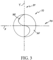
- Sinusoidal track 50 is centered on a great circle of centrifuge 10 wherein said great circle will lie colinear with the Y-axis; see Fig. 3 .
- a drive motor 70 rotates a drive wheel 75 which is engaged with track 50 within groove 55 whereby centrifuge 10 is caused to rotate about the X-axis, where the rotation follows the great circle.
- centrifuge 10 As centrifuge 10 describes simple rotational motion along said great circle and about the X-axis, it also reciprocates side to side about the Y-axis following the sinusoidal track 50. Therefore, centrifuge 10 experiences a mixture of the simple rotation about the X-axis and reciprocating motion about the Y-axis . Because of this joint motion any material that may be enclosed within centrifuge 10 will experience centripetal forces accelerating it radially in two orthogonal planes, P5 and P7 which are defined by the X and the Y axis respectively as shown in Fig. 3 . Assuming the interior of centrifuge 10 is spherical the material will form two doughnut-shaped configurations of the material which will be positioned at right angles to each other (orthogonal).
- Centrifuge 10 may be enclosed and centered within cubical structure 40 as shown in Figs. 1 and 2 . As shown, opposing drive wheels 75 may be positioned within groove 55 to constrain centrifuge 10 vertically. A pair of opposing free-rolling balls 90 may be positioned against spherical exterior surface 20 in order to constrain centrifuge 10 in the X-axis direction. A pair of opposing free-rolling wheels 100 positioned within sinusoidal groove 55 may be used to constrain centrifuge 10 in the Y-axis direction.
- the pair of opposing free-rolling balls 90, the pair of opposing free-rolling wheels 100, and the pair of drive wheels 75 being in mutually orthogonal orientations may be able to fully constrain centrifuge 10 within cubical structure 40 while allowing it to rotate about the X-axis and oscillate or reciprocate about the Y- axis.
- a controller (not shown), such as a common industrial motor controller may be used to operate drive motors 75 as to their speed and operating program, as is also well known in the art.
Landscapes
- Centrifugal Separators (AREA)
Claims (18)
- Appareil (10) pour séparer des fluides, l'appareil comprenant un moteur d'entraînement (70), et comprenant également :une surface extérieure sphérique (20), caractérisé en ce que,un point central dudit appareil est positionné à égale distance de tous les points sur ladite surface extérieure sphérique ;ledit appareil étant maintenu par un support (40) ;ladite surface extérieure sphérique comportant une piste sinusoïdale (50), dans lequelle moteur d'entraînement est en prise avec ladite piste sinusoïdale, de sorte que ledit appareil tourne avec un mouvement sinusoïdal autour dudit point central.
- Appareil selon la revendication 1, dans lequel ledit support est une structure cubique dans laquelle ledit appareil est centré.
- Appareil selon la revendication 2, dans lequel ladite piste sinusoïdale se présente sous la forme d'une rainure imprimée (55) .
- Appareil selon la revendication 3, dans lequel ledit moteur d'entraînement comporte une roue motrice (75) en prise avec ladite rainure imprimée.
- Appareil selon la revendication 4, dans lequel ledit moteur d'entraînement comporte des roues motrices opposées (75) positionnées à l'intérieur de ladite rainure imprimée.
- Appareil selon la revendication 5, dans lequel ledit support comporte une paire de billes à roulement libre opposées (90) positionnées contre ladite surface extérieure sphérique.
- Appareil selon la revendication 6, dans lequel ledit support comporte une paire de roues à roulement libre opposées (100) positionnées à l'intérieur de ladite rainure sinusoïdale.
- Appareil selon la revendication 7, dans lequel les trois paires de ladite paire de billes à roulement libre opposées, de ladite paire de roues à roulement libre opposées et de ladite paire de roues motrices sont mutuellement orthogonales.
- Procédé de rotation d'un appareil (10) pour séparer des fluides, le procédé comprenantla fourniture d'un moteur d'entraînement (70), pour faire tourner un appareil de séparation de fluides et comprenant également la formation dudit appareil avec une surface extérieure sphérique (20), caractérisé en ce que,un point central dudit appareil est positionné à égale distance de tous les points sur ladite surface extérieure sphérique ;la fixation dudit appareil dans un support (40) dans lequel ledit point central est immobile ; le placement d'une piste sinusoïdale (50) autour de ladite surface extérieure sphérique ; etla mise en prise du moteur d'entraînement avec une rainure de ladite piste sinusoïdale, faisant ainsi tourner ledit appareil dans un mouvement sinusoïdal autour dudit point central.
- Procédé selon la revendication 9, comprenant également le centrage dudit appareil à l'intérieur dudit support.
- Procédé selon la revendication 10, comprenant également l'impression de ladite rainure (55) dans ladite surface extérieure sphérique.
- Procédé selon la revendication 11, comprenant également le positionnement de ladite roue motrice (75) à l'intérieur de ladite rainure imprimée.
- Procédé selon la revendication 12, comprenant également le positionnement de roues motrices opposées (75) à l'intérieur de ladite rainure imprimée.
- Procédé selon la revendication 13, comprenant également le positionnement d'une paire de billes à roulement libre opposées (90) contre ladite surface extérieure sphérique.
- Procédé selon la revendication 14, comprenant également le positionnement d'une paire de roues à roulement libre opposées (100) à l'intérieur de ladite rainure sinusoïdale.
- Procédé selon la revendication 15, comprenant également le positionnement de ladite paire de billes à roulement libre opposées, de ladite paire de roues à roulement libre opposées et de ladite paire de roues motrices en orthogonalité mutuelle.
- Appareil selon la revendication 1, dans lequel ledit appareil est fixé de manière rotative à l'intérieur du support.
- Appareil selon la revendication 17, dans lequel une paire de billes à roulement libre opposées, une paire de roues à roulement libre opposées en prise avec ladite piste, et une paire desdits moteurs d'entraînement sont fixées par ledit support pour fixer ledit appareil.
Applications Claiming Priority (2)
| Application Number | Priority Date | Filing Date | Title |
|---|---|---|---|
| US15/963,039 US10940491B1 (en) | 2018-04-25 | 2018-04-25 | Centrifuge operating with sinusoidal motion |
| PCT/US2019/029190 WO2020036652A2 (fr) | 2018-04-25 | 2019-04-25 | Centrifugeuse formant des mouvements sinusoïdaux |
Publications (4)
| Publication Number | Publication Date |
|---|---|
| EP3784409A2 EP3784409A2 (fr) | 2021-03-03 |
| EP3784409A4 EP3784409A4 (fr) | 2022-02-16 |
| EP3784409C0 EP3784409C0 (fr) | 2024-11-06 |
| EP3784409B1 true EP3784409B1 (fr) | 2024-11-06 |
Family
ID=69524900
Family Applications (1)
| Application Number | Title | Priority Date | Filing Date |
|---|---|---|---|
| EP19850019.1A Active EP3784409B1 (fr) | 2018-04-25 | 2019-04-25 | Centrifugeuse formant des mouvements sinusoïdaux |
Country Status (3)
| Country | Link |
|---|---|
| US (1) | US10940491B1 (fr) |
| EP (1) | EP3784409B1 (fr) |
| WO (1) | WO2020036652A2 (fr) |
Family Cites Families (8)
| Publication number | Priority date | Publication date | Assignee | Title |
|---|---|---|---|---|
| US240175A (en) * | 1881-04-12 | eickhoff | ||
| AU2340177A (en) * | 1977-03-18 | 1978-09-21 | Novosib Olovyanny Kom And I Gi | Centrifugal apparatus for separating high-temperature liquid-metal mixtures |
| US5052932A (en) * | 1990-01-24 | 1991-10-01 | James Trani | Spherical simulator |
| AU1889692A (en) | 1991-06-11 | 1993-01-12 | Andrew N. Schofield & Associates Limited | Improvements in or relating to centrifuges and associated apparatus and methods |
| EP0838265B1 (fr) | 1996-09-25 | 2002-06-05 | Becton, Dickinson and Company | Mécanisme rotatif actionné par la force centrifuge pour des tubes |
| WO2007143386A2 (fr) | 2006-06-07 | 2007-12-13 | Gambro Bct, Inc. | Appareil et procédé de séparation d'un liquide composite en au moins deux composants |
| US9457398B2 (en) | 2011-06-10 | 2016-10-04 | Jean-Paul Ciardullo | Spherical centrifuge |
| GB2543815A (en) | 2015-10-30 | 2017-05-03 | Brian Duffus Leggat James | Three dimensional centrifuge |
-
2018
- 2018-04-25 US US15/963,039 patent/US10940491B1/en active Active
-
2019
- 2019-04-25 WO PCT/US2019/029190 patent/WO2020036652A2/fr not_active Ceased
- 2019-04-25 EP EP19850019.1A patent/EP3784409B1/fr active Active
Also Published As
| Publication number | Publication date |
|---|---|
| US10940491B1 (en) | 2021-03-09 |
| WO2020036652A2 (fr) | 2020-02-20 |
| EP3784409A2 (fr) | 2021-03-03 |
| US20210060581A1 (en) | 2021-03-04 |
| EP3784409A4 (fr) | 2022-02-16 |
| EP3784409C0 (fr) | 2024-11-06 |
| WO2020036652A3 (fr) | 2020-03-26 |
Similar Documents
| Publication | Publication Date | Title |
|---|---|---|
| US7943386B2 (en) | Apparatus and method for determining the volume fractions of the phases in a suspension | |
| JP3357369B2 (ja) | 遠心分離管及び適合器 | |
| US20210197212A1 (en) | Multi-axis centrifuge | |
| MX2015000814A (es) | Centrifuga compacta de alta velocidad para utilizarse con pequeños volumenes de muestra. | |
| US20210316299A1 (en) | Device and method for fluids separation by density gradient | |
| CN101312788A (zh) | 处理流体的方法和流体处理装置 | |
| US20070262034A1 (en) | Particle sedimentation apparatus and method for performing particle sedimentation | |
| EP3349897A1 (fr) | Dispositif et procédé pour la séparation de fluides par gradient de densité | |
| US10940491B1 (en) | Centrifuge operating with sinusoidal motion | |
| JP5876047B2 (ja) | 血液及び血液成分を処理するための遠心分離器 | |
| Sood et al. | Centrifugation: Basic principle, types | |
| Pretlow et al. | [22] Cell separation by gradient centrifugation methods | |
| Anderson | Preparative particle separation in density gradients | |
| EP1677889A4 (fr) | Appareil et procede de separation centrifuge | |
| JP7557730B2 (ja) | 遠心沈降による粒子の分離 | |
| Hu et al. | Centrifugation | |
| Gandhi et al. | Centrifugation | |
| WO1998008611A1 (fr) | Systeme de tri par centrifugation | |
| Basha | Centrifugation | |
| WO2021053329A1 (fr) | Pot jetable de centrifugeuse | |
| CN116020667A (zh) | 用于离心机的配平离心管、离心管套件和离心机 | |
| CN110339948A (zh) | 一种低转速微型颗粒分离装置 | |
| Plate | DN Taulbee and M. Mercedes Maroto-Valer | |
| US20210086200A1 (en) | Centrifuge having tube holders | |
| SU936978A1 (ru) | Устройство дл обработки полезных ископаемых |
Legal Events
| Date | Code | Title | Description |
|---|---|---|---|
| STAA | Information on the status of an ep patent application or granted ep patent |
Free format text: STATUS: THE INTERNATIONAL PUBLICATION HAS BEEN MADE |
|
| PUAI | Public reference made under article 153(3) epc to a published international application that has entered the european phase |
Free format text: ORIGINAL CODE: 0009012 |
|
| STAA | Information on the status of an ep patent application or granted ep patent |
Free format text: STATUS: REQUEST FOR EXAMINATION WAS MADE |
|
| 17P | Request for examination filed |
Effective date: 20201112 |
|
| AK | Designated contracting states |
Kind code of ref document: A2 Designated state(s): AL AT BE BG CH CY CZ DE DK EE ES FI FR GB GR HR HU IE IS IT LI LT LU LV MC MK MT NL NO PL PT RO RS SE SI SK SM TR |
|
| AX | Request for extension of the european patent |
Extension state: BA ME |
|
| DAV | Request for validation of the european patent (deleted) | ||
| DAX | Request for extension of the european patent (deleted) | ||
| REG | Reference to a national code |
Ref country code: DE Ref legal event code: R079 Free format text: PREVIOUS MAIN CLASS: B04B0001000000 Ipc: B04B0009080000 Ref country code: DE Ref legal event code: R079 Ref document number: 602019061656 Country of ref document: DE Free format text: PREVIOUS MAIN CLASS: B04B0001000000 Ipc: B04B0009080000 |
|
| A4 | Supplementary search report drawn up and despatched |
Effective date: 20220119 |
|
| RIC1 | Information provided on ipc code assigned before grant |
Ipc: B04B 1/00 20060101ALI20220113BHEP Ipc: B04B 7/08 20060101ALI20220113BHEP Ipc: B04B 9/00 20060101ALI20220113BHEP Ipc: B04B 9/12 20060101ALI20220113BHEP Ipc: B04B 9/08 20060101AFI20220113BHEP |
|
| GRAP | Despatch of communication of intention to grant a patent |
Free format text: ORIGINAL CODE: EPIDOSNIGR1 |
|
| STAA | Information on the status of an ep patent application or granted ep patent |
Free format text: STATUS: GRANT OF PATENT IS INTENDED |
|
| INTG | Intention to grant announced |
Effective date: 20240603 |
|
| GRAS | Grant fee paid |
Free format text: ORIGINAL CODE: EPIDOSNIGR3 |
|
| GRAA | (expected) grant |
Free format text: ORIGINAL CODE: 0009210 |
|
| STAA | Information on the status of an ep patent application or granted ep patent |
Free format text: STATUS: THE PATENT HAS BEEN GRANTED |
|
| AK | Designated contracting states |
Kind code of ref document: B1 Designated state(s): AL AT BE BG CH CY CZ DE DK EE ES FI FR GB GR HR HU IE IS IT LI LT LU LV MC MK MT NL NO PL PT RO RS SE SI SK SM TR |
|
| REG | Reference to a national code |
Ref country code: GB Ref legal event code: FG4D |
|
| REG | Reference to a national code |
Ref country code: CH Ref legal event code: EP |
|
| REG | Reference to a national code |
Ref country code: DE Ref legal event code: R096 Ref document number: 602019061656 Country of ref document: DE |
|
| REG | Reference to a national code |
Ref country code: IE Ref legal event code: FG4D |
|
| U01 | Request for unitary effect filed |
Effective date: 20241127 |
|
| U07 | Unitary effect registered |
Designated state(s): AT BE BG DE DK EE FI FR IT LT LU LV MT NL PT RO SE SI Effective date: 20241205 |
|
| PG25 | Lapsed in a contracting state [announced via postgrant information from national office to epo] |
Ref country code: HR Free format text: LAPSE BECAUSE OF FAILURE TO SUBMIT A TRANSLATION OF THE DESCRIPTION OR TO PAY THE FEE WITHIN THE PRESCRIBED TIME-LIMIT Effective date: 20241106 Ref country code: IS Free format text: LAPSE BECAUSE OF FAILURE TO SUBMIT A TRANSLATION OF THE DESCRIPTION OR TO PAY THE FEE WITHIN THE PRESCRIBED TIME-LIMIT Effective date: 20250306 |
|
| PG25 | Lapsed in a contracting state [announced via postgrant information from national office to epo] |
Ref country code: ES Free format text: LAPSE BECAUSE OF FAILURE TO SUBMIT A TRANSLATION OF THE DESCRIPTION OR TO PAY THE FEE WITHIN THE PRESCRIBED TIME-LIMIT Effective date: 20241106 |
|
| PG25 | Lapsed in a contracting state [announced via postgrant information from national office to epo] |
Ref country code: NO Free format text: LAPSE BECAUSE OF FAILURE TO SUBMIT A TRANSLATION OF THE DESCRIPTION OR TO PAY THE FEE WITHIN THE PRESCRIBED TIME-LIMIT Effective date: 20250206 |
|
| PG25 | Lapsed in a contracting state [announced via postgrant information from national office to epo] |
Ref country code: GR Free format text: LAPSE BECAUSE OF FAILURE TO SUBMIT A TRANSLATION OF THE DESCRIPTION OR TO PAY THE FEE WITHIN THE PRESCRIBED TIME-LIMIT Effective date: 20250207 |
|
| PG25 | Lapsed in a contracting state [announced via postgrant information from national office to epo] |
Ref country code: PL Free format text: LAPSE BECAUSE OF FAILURE TO SUBMIT A TRANSLATION OF THE DESCRIPTION OR TO PAY THE FEE WITHIN THE PRESCRIBED TIME-LIMIT Effective date: 20241106 |
|
| PG25 | Lapsed in a contracting state [announced via postgrant information from national office to epo] |
Ref country code: RS Free format text: LAPSE BECAUSE OF FAILURE TO SUBMIT A TRANSLATION OF THE DESCRIPTION OR TO PAY THE FEE WITHIN THE PRESCRIBED TIME-LIMIT Effective date: 20250206 |
|
| U20 | Renewal fee for the european patent with unitary effect paid |
Year of fee payment: 7 Effective date: 20250416 |
|
| PG25 | Lapsed in a contracting state [announced via postgrant information from national office to epo] |
Ref country code: SM Free format text: LAPSE BECAUSE OF FAILURE TO SUBMIT A TRANSLATION OF THE DESCRIPTION OR TO PAY THE FEE WITHIN THE PRESCRIBED TIME-LIMIT Effective date: 20241106 |
|
| PG25 | Lapsed in a contracting state [announced via postgrant information from national office to epo] |
Ref country code: SK Free format text: LAPSE BECAUSE OF FAILURE TO SUBMIT A TRANSLATION OF THE DESCRIPTION OR TO PAY THE FEE WITHIN THE PRESCRIBED TIME-LIMIT Effective date: 20241106 |
|
| PG25 | Lapsed in a contracting state [announced via postgrant information from national office to epo] |
Ref country code: CZ Free format text: LAPSE BECAUSE OF FAILURE TO SUBMIT A TRANSLATION OF THE DESCRIPTION OR TO PAY THE FEE WITHIN THE PRESCRIBED TIME-LIMIT Effective date: 20241106 |
|
| PLBE | No opposition filed within time limit |
Free format text: ORIGINAL CODE: 0009261 |
|
| STAA | Information on the status of an ep patent application or granted ep patent |
Free format text: STATUS: NO OPPOSITION FILED WITHIN TIME LIMIT |
|
| 26N | No opposition filed |
Effective date: 20250807 |
|
| REG | Reference to a national code |
Ref country code: CH Ref legal event code: H13 Free format text: ST27 STATUS EVENT CODE: U-0-0-H10-H13 (AS PROVIDED BY THE NATIONAL OFFICE) Effective date: 20251125 |
|
| PG25 | Lapsed in a contracting state [announced via postgrant information from national office to epo] |
Ref country code: MC Free format text: LAPSE BECAUSE OF FAILURE TO SUBMIT A TRANSLATION OF THE DESCRIPTION OR TO PAY THE FEE WITHIN THE PRESCRIBED TIME-LIMIT Effective date: 20241106 |
|
| PG25 | Lapsed in a contracting state [announced via postgrant information from national office to epo] |
Ref country code: CH Free format text: LAPSE BECAUSE OF NON-PAYMENT OF DUE FEES Effective date: 20250430 |
|
| U20 | Renewal fee for the european patent with unitary effect paid |
Year of fee payment: 8 Effective date: 20260305 |
|
| PGFP | Annual fee paid to national office [announced via postgrant information from national office to epo] |
Ref country code: GB Payment date: 20260305 Year of fee payment: 8 |
|
| PG25 | Lapsed in a contracting state [announced via postgrant information from national office to epo] |
Ref country code: IE Free format text: LAPSE BECAUSE OF NON-PAYMENT OF DUE FEES Effective date: 20250425 |