EP3785036B1 - Station und verfahren zur prüfung der elektrischen schaltung von elektronischen zigaretten - Google Patents
Station und verfahren zur prüfung der elektrischen schaltung von elektronischen zigaretten Download PDFInfo
- Publication number
- EP3785036B1 EP3785036B1 EP19721052.9A EP19721052A EP3785036B1 EP 3785036 B1 EP3785036 B1 EP 3785036B1 EP 19721052 A EP19721052 A EP 19721052A EP 3785036 B1 EP3785036 B1 EP 3785036B1
- Authority
- EP
- European Patent Office
- Prior art keywords
- electronic cigarettes
- electrical
- electrical circuit
- along
- control assembly
- Prior art date
- Legal status (The legal status is an assumption and is not a legal conclusion. Google has not performed a legal analysis and makes no representation as to the accuracy of the status listed.)
- Active
Links
Images



Classifications
-
- G—PHYSICS
- G01—MEASURING; TESTING
- G01R—MEASURING ELECTRIC VARIABLES; MEASURING MAGNETIC VARIABLES
- G01R27/00—Arrangements for measuring resistance, reactance, impedance, or electric characteristics derived therefrom
- G01R27/02—Measuring real or complex resistance, reactance, impedance, or other two-pole characteristics derived therefrom, e.g. time constant
-
- A—HUMAN NECESSITIES
- A24—TOBACCO; CIGARS; CIGARETTES; SIMULATED SMOKING DEVICES; SMOKERS' REQUISITES
- A24F—SMOKERS' REQUISITES; MATCH BOXES; SIMULATED SMOKING DEVICES
- A24F40/00—Electrically operated smoking devices; Component parts thereof; Manufacture thereof; Maintenance or testing thereof; Charging means specially adapted therefor
- A24F40/80—Testing
Definitions
- the present invention falls within the technical sector of electronic cigarettes.
- the invention relates to a station and a method for checking the electrical circuit of electronic cigarettes.
- a cartridge through which a liquid is vaporized by supplying electrical energy to generate aerosols.
- the electrical circuit is present in the cartridge, which comprises a heating element that causes vaporization of the liquid, and terminals made of conductive material, which are connected to the heating element.
- the electronic cigarette also comprises a power supply battery which is connected to the terminals, allowing the heating element to be heated.
- the correct functioning of the electrical circuit is essential to guarantee the quality of the finished product.
- Document WO2016/127327 discloses a device for measuring the resistance of e-cigarette atomizers arranged vertically on a support base.
- Document CN203941232 describes a device for measuring the resistance of electronic cigarettes arranged vertically on seats of a transport wheel with a vertical axis.
- the object of the present invention is to propose solutions that allow the electrical circuit of electronic cigarettes to be checked. This object is achieved by proposing a station and a method for checking the electrical circuit of electronic cigarettes according to the attached claims.
- the invention allows automatic checking of the electronic circuit of electronic cigarettes. Therefore, it is possible to guarantee the correct functioning (or rather, to guarantee the quality of the finished product, i.e. the electronic cigarettes).
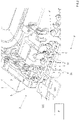
- numeral 1 indicates a check station of the electrical circuit of electronic cigarettes according to the present invention.
- the electrical circuit of an electronic cigarette (in particular of a cartridge of an electronic cigarette) comprises a heating element which causes vaporization of the liquid, along with terminals made of conductive material which are connected to the heating element.
- an electronic cigarette once completely assembled also comprises a power supply battery which is connected to the terminals, allowing heating of the heating element. Since the battery is coupled to the terminals of the electrical circuit at the very end of the assembly, the check station described here allows the electrical circuit to be checked before it is coupled with the battery.
- the electrical circuit is indicated in Figures 2 and 5 with the reference C as a representative only, without being shown in detail.
- electronic cigarettes means, in this text, parts of electronic cigarettes (in particular the cartridges, as in the illustrated case) comprising at least the electrical circuit C.
- the check station 1 comprises: at least one conveying device 2, 2' for conveying parts of electronic cigarettes E (in detail cartridges), each comprising an electrical circuit C along a advancement path P; and at least one control assembly 3 arranged along the advancement path P and comprising at least one head 30 provided with at least one electrical contact (preferably two, not visible in the attached figures).
- the head 30 can move towards the conveying device 2, 2' to contact, by means of the relative electrical contact, the electrical circuit C (the terminals) of the parts of electronic cigarettes E conveyed by the conveying device 2, 2'.
- the check station 1 also comprises: a power supply assembly (not illustrated) which supplies the contacts of the control assembly 3 with electrical energy; and a measuring assembly 8 (illustrated only schematically in the figures) connected to the control unit 3, which measures a quantity of electrical energy representative of the electric resistance and/or the inductance of the electrical circuit C.
- the conveying device 2, 2' comprising a plurality of movable units 21, 21' each arranged in order to receive the parts of electronic cigarettes E; the movable units 21, 21' being movable along the advancement path P independently from each other.
- the proposed solution allows extreme precision of the checking operations.
- the movable units 21, 21' can position themselves accurately along the advancement path P, thus allowing optimum control.
- the movable units 21, 21' comprise means for housing the parts of electronic cigarettes E, for example, the seats 200 (see Figure 2 ) or gripping means (e.g. clamps), or support members provided with suitable housings. These means are necessary because the parts of electronic cigarettes E, in particular - cartridges comprising the electrical circuit C - are parts with a particularly unstable arrangement.
- the parts of electronic cigarettes E have a predominantly longitudinal development and are maintained in a vertical position during the relative transport.
- the measured quantity of electrical energy can be a voltage (at a predetermined current), or a current (at a predetermined voltage), or a combination of voltage and current (when neither are predetermined), or a frequency of a voltage and/or a current (in the case of alternating current), or a phase shift between voltage and current (in the case of alternating current), or a time constant of voltage or current (in the case of direct current).
- the electrical resistance/inductance (or a representative value of these parameters) of the circuit can be determined thanks to the measuring assembly 8 which is able to convert it to that effect.
- the head 30 of the control assembly 3 moves along substantially vertical forward and return strokes and, in particular, perpendicular to the movable units 21, 21' which carry the parts of electronic cigarettes E to be checked (i.e. along a direction lying on a plane perpendicular to that on which the advancement path P lies).
- the conveying device 2, 2' further comprises: a guide 20, 20' arranged along the advancement path P and on which the movable units 21 can slide, 21'; a linear electric motor 202, 202' bound to the guide 20, 20' and comprising a plurality of coils (individually energizable); and a plurality of magnets (not shown) bound to the movable units 21, 21' for interacting with the coils of the linear electric motor 202, 202', allowing movement of the movable units 21, 21' along the guide 20, 20'.
- the conveying device 2, 2' is a linear motor conveyor.
- the electromagnetic field generated by the coils of the linear electric motor 202, 202' interacts with the magnets attached to the movable units 21, 21' to control their movement along the guide 20, 20'.
- the guide 20, 20' again with reference to Figures 1-4 , forms a closed-loop profile (see in particular Figure 3 ).
- the movable units 21, 21' are preferably carriages, or rather, are provided with wheels (not shown in the attached figures) for sliding along the guide 20, 20'.
- the check station 1 in accordance with this embodiment is particularly efficient thanks to the movement of the carriages 21, 21' by means of the linear motor system.
- the movable units 21, 21' can also be moved in groups of two or more, depending on the configuration of the station 1.
- the movable units 21, 21' are carried along the advancement path P, up to the control assembly 3, where they are stopped.
- the head 30 (or heads) of the control assembly 3 are only movable along vertical forward and return strokes, as previously described.
- this embodiment allows maximum precision, since checking the electrical circuit C occurs when it is stationary (i.e. with the movable units 21, 21' still).
- the movable units 21, 21' are carried along the advancement path P, up to the control assembly 3, where they continue to move (or rather, they are not stopped, but can, for example, be slowed down).
- the head 30 (or heads) of the control assembly 3 are movable, as well as along vertical forward and return strokes, also along horizontal forward and return strokes, or rather, they move to follow the movable units 21, 21' for a portion of their advancement path P.
- this embodiment allows maximum productivity, or rather, faster times, since checking of the electrical circuit C occurs when the latter is moving (or rather, when the movable units 21, 21' are moving).
- the measuring assembly 8 comprises a central control unit 8 (illustrated only in a schematic manner in the figures), configured to compare the measured quantity of electrical energy with at least one reference value, and to generate a reject signal if the measured quantity of electrical energy is different from the at least one reference value.
- the reference value can clearly be a range of values.
- the check station 1 further comprises a reject assembly 5, arranged downstream of the control assembly 3 along the advancement path P, arranged for removing the parts of electronic cigarettes E for which a reject signal has been generated, from the advancement path P.
- the reject assembly 5 comprises a gripping device 50 (for example, a pick-and-place device) which, in the event that a reject signal has been generated for a given part of an electronic cigarette E, it takes the electronic cigarette E part from the movable unit 21, 21' and transfers it outside the advancement path P.
- the gripping device 50 transfers the parts of electronic cigarettes E to be discarded into a collection container 500 (part of the reject assembly 5) outside the advancement path P.
- the control assembly 3 may further comprise at least one first optical device 6 (see in particular Figures 1 and 3 ), arranged upstream of the control assembly 3 along the advancement path P for detecting an image of the electrical circuit C of the parts of electronic cigarettes E to be checked.
- the first optical device 6 is, for example, a camera.
- the conveying device 2 comprises two linear electric motor conveyors.
- the advancement path P coincides partly with the first linear electric motor conveyor and partly with the second.
- the first optical device 6 can detect any defects already present before the checking operation, or rather, any defects present on the parts that are fed upstream.
- the control assembly 3 may further comprise at least one second optical device 7, arranged downstream of the control assembly 3 along the advancement path P, for detecting an image of the electrical circuit C of the checked parts of electronic cigarettes E.
- the second optical device 7 is, for example, a camera.
- the second optical device 7 can be provided instead of or in addition to the first optical device 6.
- the second optical device 7 can detect any defects present both before and after the checking operation. In this way, by comparing the detected images, it is possible to establish whether the defects were caused during the checking operation itself.
- the first and/or second optical device 7 it is also possible to visually check the state of the electrical circuit C, in particular of the terminals (contacts), to possibly allow an association between detected malfunction and image (e.g. a detected geometric defect).
- the present invention further relates to a method for checking the electrical circuit C of electronic cigarettes E (refer to Figures 1-4 ). This method can be implemented, for example, with the check station 1 described above.
- the method includes the steps of:
- the method described above allows the electrical circuits C to be checked in a particularly precise and effective manner, since the electrical circuits are moved independently from each other.
- the step of measuring a quantity of electrical energy representative of the electric resistance and/or inductance of the checked electrical circuit C comprises the sub-steps of:
- the present invention relates to a check station 1 comprising: at least one conveying device 2, for conveying parts of electronic cigarettes E comprising electrical circuits C along an advancement path P; and a control assembly 3 arranged along the advancement path P comprising at least one head 30 provided with at least one electrical contact which is movable towards the conveying device 2, to contact (by means of the relative electrical contact) the electrical circuit C (the terminals) of the electronic cigarettes E conveyed by the conveying device 2.
- the check station 1 further comprises: a power supply assembly (not illustrated) which supplies the contacts of the control assembly 3 with electrical energy; and a measuring assembly 8 connected to the control unit 3, which measures a quantity of electrical energy representative of the electric resistance and/or the inductance of the electrical circuit C.
- the conveying device 2 comprising a belt 9 comprising means for housing the parts of electronic cigarettes E (comprising the electrical circuit C) and moving them along the advancement path P.
- the belt 9 generally means any flat conveyor (for example, a tape), for example, a closed-loop belt (shown only partially in Figure 5 ).
- This second embodiment represents an alternative to the first embodiment described above, aimed at solving the same technical problem.
- the means for housing the parts of electronic cigarettes E are, for example, seats 90 (as in the illustrated case) or gripping means (e.g. clamps) or support members provided with suitable housings. These means are necessary because the parts of electronic cigarettes E, for example - cartridges comprising the electrical circuit C - are parts with a particularly unstable arrangement.
- the parts (cartridges) of electronic cigarettes E are maintained with vertical alignment during the relative transport.
- guiding side walls may be provided for stabilizing the parts of electronic cigarettes E during transport.
- the measured quantity of electrical energy can be a voltage (at a predetermined current), or a current (at a predetermined voltage), or a combination of voltage and current (when neither are predetermined), or a frequency of a voltage and/or a current (in the case of alternating current), or a phase shift between voltage and current (in the case of alternating current), or a time constant of voltage or current (in the case of direct current).
- the electrical resistance/inductance (or a representative value of these parameters) of the circuit can be determined thanks to the measuring assembly 8 which is able to convert it to that effect.
- the head 30 of the control assembly 3 moves along substantially vertical forward and return strokes. In other words, the head 30 of the control assembly 3 moves perpendicularly to the conveying device 2, or rather, to the parts of electronic cigarettes E conveyed along the advancement path P.
- the belt 9 is moved to carry the parts up to the control assembly 3; then the belt 9 is stopped and, therefore, the parts are stationary at the control assembly 3 (in other words, the belt 9 is moved stepwise, or rather, with an alternating movement).
- the head 30 (or heads) of the control unit 3 are only movable along vertical forward and return strokes, as previously anticipated.
- this embodiment allows maximum precision, since checking of the electrical circuit C occurs when it is stationary.
- the belt 9 is moved to carry the parts along the advancement path P, up to the control assembly 3, where they continue to be moved (the belt 9 is not stopped, but moves continuously).
- the head 30 (or heads) of the control assembly 3 are movable, as well as along vertical forward and return strokes, also along horizontal forward and return strokes, or rather, they move to follow the parts carried by the belt 9 for a portion of their advancement path P.
- this embodiment allows maximum productivity, or rather, faster times, since checking of the electrical circuit C occurs when the latter is moving (or rather, when the belt 9 is moving).
- the measuring assembly 8 comprises a central control unit 8 (illustrated only schematically) configured to compare the measured quantity of electrical energy with at least one reference value, and to generate a reject signal if the measured quantity of electrical energy is different from the at least one reference value.
- the reference value can clearly be a range of values.
- the check station 1 further comprises a reject assembly 5, arranged downstream of the control assembly 3 along the advancement path P, arranged for removing the parts of electronic cigarettes E for which a reject signal has been generated, from the advancement path P.
- the reject assembly 5 comprises a gripping device 50 (for example, a pick-and-place device) which, in the event that a reject signal has been generated for a given part of an electronic cigarette E, it takes the electronic cigarette part from the belt 9 and transfers it outside the advancement path P.
- the gripping device 50 transfers the parts of electronic cigarettes E to be discarded into a collection container 500 outside the advancement path P.
- the control assembly 3 may further comprise at least one first optical device 6 (not visible in Figure 5 ) arranged upstream of the control assembly 3 along the advancement path P for detecting an image of the electrical circuit C of the parts of electronic cigarettes E to be checked.
- the first optical device 6 is, for example a camera.
- the first optical device can detect any defects already present before the checking operation, or rather, any defects present on the parts of electronic cigarettes E that are fed upstream (i.e. as supplied or assembled).
- the control assembly 3 may further comprise at least one second optical device 7 arranged downstream of the control assembly 3 for detecting an image of the electrical circuit C of the checked parts of electronic cigarettes E.
- the second optical device 7 is, for example, a camera 7.
- the second optical device 7 can be provided instead of or in addition to the first optical device.
- the second optical device 7 can detect any defects present both before and after the checking operation. In this way, by comparing the detected images, it is possible to establish whether the defects were caused during the checking operation itself.
- the first and/or second optical device 7 it is also possible to visually check the state of the electrical circuit C, in particular of the terminals (contacts), to possibly allow an association between detected malfunction and image (e.g. a detected geometric defect).
- the present invention further relates to a method for checking the electrical circuit C of electronic cigarettes E (refer to Figure 5 ).
- This method can be implemented, for example, with the check station 1 described above.
- the method includes the steps of:
- the method described above allows the electrical circuits to be checked in a particularly stable and effective manner, and is constructively simple.
- the step of measuring a quantity of electrical energy representative of the electric resistance and/or inductance of the checked electrical circuit C comprises the sub-steps of:
- the present invention also relates to an assembling machine (not illustrated) for electronic cigarettes E comprising a plurality of assembling stations arranged along an assembling path, and at least one first check station 1 for checking the electrical circuit C of electronic cigarettes E, and which is arranged upstream and/or downstream of the assembling stations and/or interposed between the assembling stations.
- the check station 1 can be of the type according to the first or the second embodiment described above.
- the present invention further relates to a filling machine M of electronic cigarettes E (clearly visible in Figure 3 ) comprising at least one filling station R for filling electronic cigarettes E with a product to be vaporized; and at least one first check station 1 for checking the electrical circuit C of electronic cigarettes E arranged upstream and/or downstream of the filling station R.
- the filling station R comprises, for example, a plurality of nozzles which dispense the product inside the parts of electronic cigarettes E (or rather inside the relative cartridges).
- check station 1 of the filling machine M is shown according to the first embodiment, this can also be of the type according to the second embodiment described above.
- the assembling machine and the filling machine M described above each integrate the checking function of the electrical circuit C of the electronic cigarettes E.
- the assembling machine and the filling machine M can also be connected together to form a single system.
Landscapes
- Physics & Mathematics (AREA)
- General Physics & Mathematics (AREA)
- Manufacturing Of Cigar And Cigarette Tobacco (AREA)
- Monitoring And Testing Of Transmission In General (AREA)
Claims (12)
- Station (1) zum Prüfen der elektrischen Schaltung (C) elektronischer Zigaretten (E), die Folgendes umfasst:eine Fördervorrichtung (2, 2') zum Fördern von Teilen elektronischer Zigaretten (E), die je eine elektrische Schaltung (C) umfassen, entlang einer Vorschubstrecke (P);eine Steuerbaugruppe (3), die entlang der Vorschubstrecke (P) angeordnet ist und mindestens einen Kopf (30), der mindestens einen elektrischen Kontakt aufweist und zur Fördervorrichtung (2, 2') hin bewegbar ist, umfasst, um - mittels seines elektrischen Kontakts- die elektrische Schaltung (C) der durch die Fördervorrichtung (2, 2') geförderten elektronischen Zigaretten (E) zu kontaktieren;eine Stromversorgungsbaugruppe, die die elektrischen Kontakte der Steuerbaugruppe (3) mit elektrischer Energie versorgt;eine mit der Steuerbaugruppe (3) verbundene Messbaugruppe (8), die eine Größe der elektrischen Energie, die repräsentativ für den elektrischen Widerstand und/oder die Induktivität der elektrischen Schaltung (C) ist, misst;wobei die Fördervorrichtung (2, 2') eine Vielzahl bewegbarer Einheiten (21, 21'), die je derart angeordnet sind, dass sie die Teile elektronischer Zigaretten (E) aufnehmen, umfasst; wobei die bewegbaren Einheiten (21, 21') entlang der Vorschubstrecke (P) unabhängig voneinander bewegbar sind.
- Station (1) nach Anspruch 1, wobei die Fördervorrichtung (2, 2') ferner Folgendes umfasst: eine Führung (20, 20'), die entlang der Vorschubstrecke (P) positioniert ist und auf der die bewegbaren Einheiten (21, 21') entlanggleiten können; einen Elektrolinearmotor (202, 202'), der an die Führung (20, 20') angefügt ist und eine Vielzahl von Spulen umfasst; eine Vielzahl von an die bewegbaren Einheiten (21, 21') angefügten Magneten zum Wechselwirken mit den Spulen des Elektrolinearmotors (202, 202'), wodurch ermöglicht wird, dass sich die bewegbaren Einheiten (21, 21') entlang der Führung (20, 20') bewegen.
- Station (1) zum Prüfen der elektrischen Schaltung (C) elektronischer Zigaretten (E), die Folgendes umfasst:eine Fördervorrichtung (2) zum Fördern von Teilen elektronischer Zigaretten (E), die je eine elektrische Schaltung (C) umfassen, entlang einer Vorschubstrecke (P);eine Steuerbaugruppe (3), die entlang der Vorschubstrecke (P) angeordnet ist und mindestens einen Kopf (30), der mindestens einen elektrischen Kontakt aufweist und zur Fördervorrichtung (2) hin bewegbar ist, umfasst, um - mittels seines elektrischen Kontakts - die elektrische Schaltung (C) der durch die Fördervorrichtung (2,) geförderten elektronischen Zigaretten (E) zu kontaktieren;eine Stromversorgungsbaugruppe, die die elektrischen Kontakte der Steuerbaugruppe (3) mit elektrischer Energie versorgt;eine mit der Steuerbaugruppe (3) verbundene Messbaugruppe (8), die eine Größe der elektrischen Energie, die repräsentativ für den elektrischen Widerstand und/oder die Induktivität der elektrischen Schaltung (C) ist, misst;wobei die Fördervorrichtung (2) ein Band (9) umfasst, das Mittel zum Aufnehmen der Teile elektronischer Zigaretten (E) und Bewegen dieser Teile entlang der Vorschubstrecke (P) umfasst.
- Station (1) nach einem der vorhergehenden Ansprüche, wobei die Messbaugruppe (8) eine zentrale Steuereinheit (8) umfasst, die konfiguriert ist, um den Wert der gemessenen Größe der elektrischen Energie mit mindestens einem Bezugswert zu vergleichen und ein Aussonderungssignal zu generieren, wenn der Wert der gemessenen Größe der elektrischen Energie von dem mindestens einen Bezugswert abweicht.
- Station (1) nach dem vorhergehenden Anspruch, die ferner eine Aussonderungsbaugruppe (5) umfasst, die entlang der Vorschubstrecke (P) nach der Steuerbaugruppe (3) angeordnet ist sowie derart angeordnet ist, dass sie die Teile elektronischer Zigaretten (E), für die ein Aussonderungssignal generiert worden ist, von der Vorschubstrecke (P) entfernt.
- Station (1) nach einem der vorhergehenden Ansprüche, wobei die Steuerbaugruppe (3) ferner mindestens eine entlang der Vorschubstrecke (P) vor der Steuerbaugruppe (3) angeordnete erste optische Vorrichtung (6) zum Detektieren eines Bilds der elektrischen Schaltung (C) der zu prüfenden Teile elektronischer Zigaretten (E) umfasst.
- Station (1) nach einem der vorhergehenden Ansprüche, wobei die Steuerbaugruppe (3) ferner mindestens eine nach der Steuerbaugruppe (3) angeordnete zweite optische Vorrichtung (7) zum Detektieren eines Bilds der elektrischen Schaltung (C) der geprüften Teile elektronischer Zigaretten (E) umfasst.
- Montagemaschine für elektronische Zigaretten (E), die eine Vielzahl von entlang einer Montagestrecke angeordneten Montagestationen und mindestens eine erste Station (1) zum Prüfen der elektrischen Schaltung (C) elektronischer Zigaretten (E) nach einem der vorhergehenden Ansprüche, die vor und/oder nach den Montagestationen angeordnet und/oder zwischen die Montagestationen gesetzt ist, umfasst.
- Füllmaschine (M) für elektronische Zigaretten (E), die mindestens Folgendes umfasst: eine Füllstation (R) zum Befüllen elektronischer Zigaretten (E) mit einem zu verdampfenden Produkt; und mindestens eine erste Station (1) zum Prüfen der elektrischen Schaltung (C) elektronischer Zigaretten (E) nach einem der vorhergehenden Ansprüche, die vor und/oder nach der Füllstation (R) angeordnet ist.
- Verfahren (1) zum Prüfen der elektrischen Schaltung (C) elektronischer Zigaretten (E), das folgende Schritte umfasst:Fördern von Teilen elektronischer Zigaretten (E), die elektrische Schaltungen (C) umfassen, entlang einer Vorschubstrecke (P) in unabhängigen bewegbaren Gruppen zu einer Steuerbaugruppe (3) hin;Kontaktieren der elektrischen Schaltung (C) der elektronischen Zigaretten (E), die entlang der Vorschubstrecke (P) gefördert werden, mittels mindestens eines elektrischen Kontakts;Messen einer Größe der elektrischen Energie, die repräsentativ für den elektrischen Widerstand und/oder die Induktivität der geprüften elektrischen Schaltung (C) ist.
- Verfahren (1) zum Prüfen der elektrischen Schaltung (C) elektronischer Zigaretten (E), das folgende Schritte umfasst:Fördern von Teilen elektronischer Zigaretten (E), die elektrische Schaltungen (C) umfassen, entlang einer Vorschubstrecke (P) mittels eines Bands (9) zu einer Steuerbaugruppe (3) hin;Kontaktieren der elektrischen Schaltung (C) der elektronischen Zigaretten (E), die entlang der Vorschubstrecke (P) gefördert werden, mittels mindestens eines elektrischen Kontakts;Messen einer Größe der elektrischen Energie, die repräsentativ für den elektrischen Widerstand und/oder die Induktivität der geprüften elektrischen Schaltung (C) ist.
- Verfahren nach Anspruch 10 oder 11, wobei der Schritt des Messens einer Größe der elektrischen Energie, die repräsentativ für den elektrischen Widerstand und/oder die Induktivität der elektrischen Schaltung (C) ist, folgende Teilschritte umfasst:- Vergleichen des Werts der gemessenen Größe der elektrischen Energie mit mindestens einem Bezugswert; und- Generieren eines Aussonderungssignals, wenn der Wert der gemessenen Größe der elektrischen Energie von dem mindestens einen Bezugswert abweicht.
Applications Claiming Priority (2)
| Application Number | Priority Date | Filing Date | Title |
|---|---|---|---|
| IT102018000004814A IT201800004814A1 (it) | 2018-04-24 | 2018-04-24 | Stazione e metodo di controllo del circuito elettrico di sigarette elettroniche |
| PCT/IB2019/052299 WO2019207373A1 (en) | 2018-04-24 | 2019-03-21 | A station and method for checking the electrical circuit of electronic cigarettes |
Publications (3)
| Publication Number | Publication Date |
|---|---|
| EP3785036A1 EP3785036A1 (de) | 2021-03-03 |
| EP3785036B1 true EP3785036B1 (de) | 2022-05-04 |
| EP3785036B2 EP3785036B2 (de) | 2025-07-23 |
Family
ID=62952294
Family Applications (1)
| Application Number | Title | Priority Date | Filing Date |
|---|---|---|---|
| EP19721052.9A Active EP3785036B2 (de) | 2018-04-24 | 2019-03-21 | Station zur prüfung der elektrischen schaltung von elektronischen zigaretten |
Country Status (5)
| Country | Link |
|---|---|
| EP (1) | EP3785036B2 (de) |
| ES (1) | ES2915651T3 (de) |
| IT (1) | IT201800004814A1 (de) |
| PL (1) | PL3785036T5 (de) |
| WO (1) | WO2019207373A1 (de) |
Citations (15)
| Publication number | Priority date | Publication date | Assignee | Title |
|---|---|---|---|---|
| US3408565A (en) | 1966-03-02 | 1968-10-29 | Philco Ford Corp | Apparatus for sequentially testing electrical components under controlled environmental conditions including a component support mating test head |
| US4818933A (en) | 1986-10-08 | 1989-04-04 | Hewlett-Packard Company | Board fixturing system |
| US5237510A (en) | 1990-03-20 | 1993-08-17 | Fujitsu Limited | Transportation system for products operated on by manufacturing on testing units |
| US5969752A (en) | 1998-06-15 | 1999-10-19 | Electro Scientific Industries | Multi-function viewer/tester for miniature electric components |
| US6094061A (en) | 1997-12-31 | 2000-07-25 | Gte Communication Systems Corporation | Automated testing method for electronic circuitry |
| US20030030459A1 (en) | 2001-08-10 | 2003-02-13 | James Sabey | Apparatus and methods for testing circuit boards |
| US6563301B2 (en) | 2001-04-30 | 2003-05-13 | Nokia Mobile Phones Ltd. | Advanced production test method and apparatus for testing electronic devices |
| WO2004103792A1 (de) | 2003-05-21 | 2004-12-02 | Schierholz-Translift Schweiz Ag | Schienenanordnung, weiche und transportvorrichtung mit magnetostriktiven sensoren |
| US6876107B2 (en) | 2002-06-05 | 2005-04-05 | Jacobs Automation | Controlled motion system |
| US20130074724A1 (en) | 2009-01-23 | 2013-03-28 | Magnemotion, Inc. | Transport system powered by short block linear synchronous motors and switching mechanism |
| WO2015007342A1 (en) | 2013-07-19 | 2015-01-22 | Wilco Ag | Method of in-line testing devices and testing apparatus |
| WO2016119171A1 (zh) | 2015-01-29 | 2016-08-04 | 惠州市吉瑞科技有限公司 | 一种阻值测试设备 |
| WO2016127327A1 (zh) | 2015-02-11 | 2016-08-18 | 惠州市吉瑞科技有限公司 | 一种用于测量电子烟的雾化器阻值的测量设备 |
| WO2016207136A1 (en) | 2015-06-26 | 2016-12-29 | Kone Corporation | Electric linear motor |
| US9586760B2 (en) | 2011-12-28 | 2017-03-07 | Advantest Corporation | Electronic component transfer shuttle |
Family Cites Families (1)
| Publication number | Priority date | Publication date | Assignee | Title |
|---|---|---|---|---|
| CN203941232U (zh) * | 2014-06-11 | 2014-11-12 | 昂纳自动化技术(深圳)有限公司 | 一种雾化器电阻在线检测装置 |
-
2018
- 2018-04-24 IT IT102018000004814A patent/IT201800004814A1/it unknown
-
2019
- 2019-03-21 EP EP19721052.9A patent/EP3785036B2/de active Active
- 2019-03-21 ES ES19721052T patent/ES2915651T3/es active Active
- 2019-03-21 WO PCT/IB2019/052299 patent/WO2019207373A1/en not_active Ceased
- 2019-03-21 PL PL19721052.9T patent/PL3785036T5/pl unknown
Patent Citations (15)
| Publication number | Priority date | Publication date | Assignee | Title |
|---|---|---|---|---|
| US3408565A (en) | 1966-03-02 | 1968-10-29 | Philco Ford Corp | Apparatus for sequentially testing electrical components under controlled environmental conditions including a component support mating test head |
| US4818933A (en) | 1986-10-08 | 1989-04-04 | Hewlett-Packard Company | Board fixturing system |
| US5237510A (en) | 1990-03-20 | 1993-08-17 | Fujitsu Limited | Transportation system for products operated on by manufacturing on testing units |
| US6094061A (en) | 1997-12-31 | 2000-07-25 | Gte Communication Systems Corporation | Automated testing method for electronic circuitry |
| US5969752A (en) | 1998-06-15 | 1999-10-19 | Electro Scientific Industries | Multi-function viewer/tester for miniature electric components |
| US6563301B2 (en) | 2001-04-30 | 2003-05-13 | Nokia Mobile Phones Ltd. | Advanced production test method and apparatus for testing electronic devices |
| US20030030459A1 (en) | 2001-08-10 | 2003-02-13 | James Sabey | Apparatus and methods for testing circuit boards |
| US6876107B2 (en) | 2002-06-05 | 2005-04-05 | Jacobs Automation | Controlled motion system |
| WO2004103792A1 (de) | 2003-05-21 | 2004-12-02 | Schierholz-Translift Schweiz Ag | Schienenanordnung, weiche und transportvorrichtung mit magnetostriktiven sensoren |
| US20130074724A1 (en) | 2009-01-23 | 2013-03-28 | Magnemotion, Inc. | Transport system powered by short block linear synchronous motors and switching mechanism |
| US9586760B2 (en) | 2011-12-28 | 2017-03-07 | Advantest Corporation | Electronic component transfer shuttle |
| WO2015007342A1 (en) | 2013-07-19 | 2015-01-22 | Wilco Ag | Method of in-line testing devices and testing apparatus |
| WO2016119171A1 (zh) | 2015-01-29 | 2016-08-04 | 惠州市吉瑞科技有限公司 | 一种阻值测试设备 |
| WO2016127327A1 (zh) | 2015-02-11 | 2016-08-18 | 惠州市吉瑞科技有限公司 | 一种用于测量电子烟的雾化器阻值的测量设备 |
| WO2016207136A1 (en) | 2015-06-26 | 2016-12-29 | Kone Corporation | Electric linear motor |
Also Published As
| Publication number | Publication date |
|---|---|
| PL3785036T5 (pl) | 2025-10-06 |
| EP3785036A1 (de) | 2021-03-03 |
| IT201800004814A1 (it) | 2019-10-24 |
| WO2019207373A1 (en) | 2019-10-31 |
| PL3785036T3 (pl) | 2022-09-12 |
| ES2915651T3 (es) | 2022-06-24 |
| EP3785036B2 (de) | 2025-07-23 |
Similar Documents
| Publication | Publication Date | Title |
|---|---|---|
| US10287105B2 (en) | Conveying apparatuses | |
| CN105492157B (zh) | 用于连续传送和对接焊接金属板件的方法以及所述方法的使用 | |
| EP2874480B1 (de) | Komponentenmontagesystem | |
| US20180016047A1 (en) | Bag making and packaging machine | |
| JP7311687B2 (ja) | 実装機械にアセンブリ部品を供給するための2次元ロボットシステム | |
| CN109607290A (zh) | 料带分装机、料带分装机系统及料带分装方法 | |
| KR101732449B1 (ko) | 반송 장치 | |
| JP6660686B2 (ja) | テーピング装置 | |
| EP3785036B2 (de) | Station zur prüfung der elektrischen schaltung von elektronischen zigaretten | |
| CN105683066A (zh) | 用于沿输送方向沿着输送路径输送工件,特别是电路板的输送设备 | |
| EP0677444A1 (de) | Optisches Kontrollverfahren für Gegenstände | |
| EP3785037B1 (de) | Station und verfahren zur prüfung der elektrischen schaltung von elektronischen zigaretten | |
| CN109176038B (zh) | 汽车轮速传感器生产设备 | |
| CN109483247B (zh) | 轮速传感器组装设备 | |
| GB842448A (en) | Electronic component assembly apparatus | |
| JP6453742B2 (ja) | 半田付け装置、および半田付け方法 | |
| CA3220948A1 (en) | Apparatus for cutting and conveying a strip of material for the production of electrical energy storage devices and relative method | |
| EP1065143B1 (de) | Verpackungsmaschine, insbesondere für Zigaretten | |
| JP6495204B2 (ja) | 搬送装置 | |
| JP6995502B2 (ja) | 電子タバコの加熱部の電気回路をレーザー半田付けするための方法および装置 | |
| KR20190021278A (ko) | 마킹시스템 | |
| JP7357140B2 (ja) | 電源遮断装置および電源遮断方法 | |
| GB2165810A (en) | Apparatus for feeding components through a work station | |
| CN219393199U (zh) | 电容盖板芯组自动入铝壳装置 | |
| CN115938823B (zh) | 一种电容器赋能设备 |
Legal Events
| Date | Code | Title | Description |
|---|---|---|---|
| STAA | Information on the status of an ep patent application or granted ep patent |
Free format text: STATUS: UNKNOWN |
|
| STAA | Information on the status of an ep patent application or granted ep patent |
Free format text: STATUS: THE INTERNATIONAL PUBLICATION HAS BEEN MADE |
|
| PUAI | Public reference made under article 153(3) epc to a published international application that has entered the european phase |
Free format text: ORIGINAL CODE: 0009012 |
|
| STAA | Information on the status of an ep patent application or granted ep patent |
Free format text: STATUS: REQUEST FOR EXAMINATION WAS MADE |
|
| 17P | Request for examination filed |
Effective date: 20201006 |
|
| AK | Designated contracting states |
Kind code of ref document: A1 Designated state(s): AL AT BE BG CH CY CZ DE DK EE ES FI FR GB GR HR HU IE IS IT LI LT LU LV MC MK MT NL NO PL PT RO RS SE SI SK SM TR |
|
| AX | Request for extension of the european patent |
Extension state: BA ME |
|
| RIN1 | Information on inventor provided before grant (corrected) |
Inventor name: MORETTI, CARLO Inventor name: TESTONI, LUCA Inventor name: CUCCHI, MANUELE Inventor name: RENCO, FRANCESCO Inventor name: LANZARINI, LUCA Inventor name: FEDERICI, LUCA |
|
| DAV | Request for validation of the european patent (deleted) | ||
| DAX | Request for extension of the european patent (deleted) | ||
| GRAP | Despatch of communication of intention to grant a patent |
Free format text: ORIGINAL CODE: EPIDOSNIGR1 |
|
| STAA | Information on the status of an ep patent application or granted ep patent |
Free format text: STATUS: GRANT OF PATENT IS INTENDED |
|
| INTG | Intention to grant announced |
Effective date: 20220125 |
|
| GRAS | Grant fee paid |
Free format text: ORIGINAL CODE: EPIDOSNIGR3 |
|
| GRAA | (expected) grant |
Free format text: ORIGINAL CODE: 0009210 |
|
| STAA | Information on the status of an ep patent application or granted ep patent |
Free format text: STATUS: THE PATENT HAS BEEN GRANTED |
|
| AK | Designated contracting states |
Kind code of ref document: B1 Designated state(s): AL AT BE BG CH CY CZ DE DK EE ES FI FR GB GR HR HU IE IS IT LI LT LU LV MC MK MT NL NO PL PT RO RS SE SI SK SM TR |
|
| REG | Reference to a national code |
Ref country code: GB Ref legal event code: FG4D |
|
| REG | Reference to a national code |
Ref country code: CH Ref legal event code: EP |
|
| REG | Reference to a national code |
Ref country code: AT Ref legal event code: REF Ref document number: 1489604 Country of ref document: AT Kind code of ref document: T Effective date: 20220515 |
|
| REG | Reference to a national code |
Ref country code: DE Ref legal event code: R096 Ref document number: 602019014552 Country of ref document: DE |
|
| REG | Reference to a national code |
Ref country code: IE Ref legal event code: FG4D |
|
| REG | Reference to a national code |
Ref country code: NL Ref legal event code: FP |
|
| REG | Reference to a national code |
Ref country code: ES Ref legal event code: FG2A Ref document number: 2915651 Country of ref document: ES Kind code of ref document: T3 Effective date: 20220624 |
|
| REG | Reference to a national code |
Ref country code: LT Ref legal event code: MG9D |
|
| REG | Reference to a national code |
Ref country code: AT Ref legal event code: MK05 Ref document number: 1489604 Country of ref document: AT Kind code of ref document: T Effective date: 20220504 |
|
| PG25 | Lapsed in a contracting state [announced via postgrant information from national office to epo] |
Ref country code: SE Free format text: LAPSE BECAUSE OF FAILURE TO SUBMIT A TRANSLATION OF THE DESCRIPTION OR TO PAY THE FEE WITHIN THE PRESCRIBED TIME-LIMIT Effective date: 20220504 Ref country code: PT Free format text: LAPSE BECAUSE OF FAILURE TO SUBMIT A TRANSLATION OF THE DESCRIPTION OR TO PAY THE FEE WITHIN THE PRESCRIBED TIME-LIMIT Effective date: 20220905 Ref country code: NO Free format text: LAPSE BECAUSE OF FAILURE TO SUBMIT A TRANSLATION OF THE DESCRIPTION OR TO PAY THE FEE WITHIN THE PRESCRIBED TIME-LIMIT Effective date: 20220804 Ref country code: LT Free format text: LAPSE BECAUSE OF FAILURE TO SUBMIT A TRANSLATION OF THE DESCRIPTION OR TO PAY THE FEE WITHIN THE PRESCRIBED TIME-LIMIT Effective date: 20220504 Ref country code: HR Free format text: LAPSE BECAUSE OF FAILURE TO SUBMIT A TRANSLATION OF THE DESCRIPTION OR TO PAY THE FEE WITHIN THE PRESCRIBED TIME-LIMIT Effective date: 20220504 Ref country code: GR Free format text: LAPSE BECAUSE OF FAILURE TO SUBMIT A TRANSLATION OF THE DESCRIPTION OR TO PAY THE FEE WITHIN THE PRESCRIBED TIME-LIMIT Effective date: 20220805 Ref country code: FI Free format text: LAPSE BECAUSE OF FAILURE TO SUBMIT A TRANSLATION OF THE DESCRIPTION OR TO PAY THE FEE WITHIN THE PRESCRIBED TIME-LIMIT Effective date: 20220504 Ref country code: BG Free format text: LAPSE BECAUSE OF FAILURE TO SUBMIT A TRANSLATION OF THE DESCRIPTION OR TO PAY THE FEE WITHIN THE PRESCRIBED TIME-LIMIT Effective date: 20220804 Ref country code: AT Free format text: LAPSE BECAUSE OF FAILURE TO SUBMIT A TRANSLATION OF THE DESCRIPTION OR TO PAY THE FEE WITHIN THE PRESCRIBED TIME-LIMIT Effective date: 20220504 |
|
| PG25 | Lapsed in a contracting state [announced via postgrant information from national office to epo] |
Ref country code: RS Free format text: LAPSE BECAUSE OF FAILURE TO SUBMIT A TRANSLATION OF THE DESCRIPTION OR TO PAY THE FEE WITHIN THE PRESCRIBED TIME-LIMIT Effective date: 20220504 Ref country code: LV Free format text: LAPSE BECAUSE OF FAILURE TO SUBMIT A TRANSLATION OF THE DESCRIPTION OR TO PAY THE FEE WITHIN THE PRESCRIBED TIME-LIMIT Effective date: 20220504 Ref country code: IS Free format text: LAPSE BECAUSE OF FAILURE TO SUBMIT A TRANSLATION OF THE DESCRIPTION OR TO PAY THE FEE WITHIN THE PRESCRIBED TIME-LIMIT Effective date: 20220904 |
|
| PG25 | Lapsed in a contracting state [announced via postgrant information from national office to epo] |
Ref country code: SM Free format text: LAPSE BECAUSE OF FAILURE TO SUBMIT A TRANSLATION OF THE DESCRIPTION OR TO PAY THE FEE WITHIN THE PRESCRIBED TIME-LIMIT Effective date: 20220504 Ref country code: SK Free format text: LAPSE BECAUSE OF FAILURE TO SUBMIT A TRANSLATION OF THE DESCRIPTION OR TO PAY THE FEE WITHIN THE PRESCRIBED TIME-LIMIT Effective date: 20220504 Ref country code: RO Free format text: LAPSE BECAUSE OF FAILURE TO SUBMIT A TRANSLATION OF THE DESCRIPTION OR TO PAY THE FEE WITHIN THE PRESCRIBED TIME-LIMIT Effective date: 20220504 Ref country code: EE Free format text: LAPSE BECAUSE OF FAILURE TO SUBMIT A TRANSLATION OF THE DESCRIPTION OR TO PAY THE FEE WITHIN THE PRESCRIBED TIME-LIMIT Effective date: 20220504 Ref country code: DK Free format text: LAPSE BECAUSE OF FAILURE TO SUBMIT A TRANSLATION OF THE DESCRIPTION OR TO PAY THE FEE WITHIN THE PRESCRIBED TIME-LIMIT Effective date: 20220504 Ref country code: CZ Free format text: LAPSE BECAUSE OF FAILURE TO SUBMIT A TRANSLATION OF THE DESCRIPTION OR TO PAY THE FEE WITHIN THE PRESCRIBED TIME-LIMIT Effective date: 20220504 |
|
| REG | Reference to a national code |
Ref country code: DE Ref legal event code: R026 Ref document number: 602019014552 Country of ref document: DE |
|
| PLBI | Opposition filed |
Free format text: ORIGINAL CODE: 0009260 |
|
| PLAX | Notice of opposition and request to file observation + time limit sent |
Free format text: ORIGINAL CODE: EPIDOSNOBS2 |
|
| 26 | Opposition filed |
Opponent name: FOCKE & CO. (GMBH & CO. KG) Effective date: 20230131 |
|
| PG25 | Lapsed in a contracting state [announced via postgrant information from national office to epo] |
Ref country code: AL Free format text: LAPSE BECAUSE OF FAILURE TO SUBMIT A TRANSLATION OF THE DESCRIPTION OR TO PAY THE FEE WITHIN THE PRESCRIBED TIME-LIMIT Effective date: 20220504 |
|
| PG25 | Lapsed in a contracting state [announced via postgrant information from national office to epo] |
Ref country code: SI Free format text: LAPSE BECAUSE OF FAILURE TO SUBMIT A TRANSLATION OF THE DESCRIPTION OR TO PAY THE FEE WITHIN THE PRESCRIBED TIME-LIMIT Effective date: 20220504 |
|
| PLBB | Reply of patent proprietor to notice(s) of opposition received |
Free format text: ORIGINAL CODE: EPIDOSNOBS3 |
|
| P01 | Opt-out of the competence of the unified patent court (upc) registered |
Effective date: 20230524 |
|
| PG25 | Lapsed in a contracting state [announced via postgrant information from national office to epo] |
Ref country code: MC Free format text: LAPSE BECAUSE OF FAILURE TO SUBMIT A TRANSLATION OF THE DESCRIPTION OR TO PAY THE FEE WITHIN THE PRESCRIBED TIME-LIMIT Effective date: 20220504 |
|
| REG | Reference to a national code |
Ref country code: CH Ref legal event code: PL |
|
| GBPC | Gb: european patent ceased through non-payment of renewal fee |
Effective date: 20230321 |
|
| REG | Reference to a national code |
Ref country code: BE Ref legal event code: MM Effective date: 20230331 |
|
| PG25 | Lapsed in a contracting state [announced via postgrant information from national office to epo] |
Ref country code: LU Free format text: LAPSE BECAUSE OF NON-PAYMENT OF DUE FEES Effective date: 20230321 |
|
| REG | Reference to a national code |
Ref country code: IE Ref legal event code: MM4A |
|
| PG25 | Lapsed in a contracting state [announced via postgrant information from national office to epo] |
Ref country code: GB Free format text: LAPSE BECAUSE OF NON-PAYMENT OF DUE FEES Effective date: 20230321 |
|
| PG25 | Lapsed in a contracting state [announced via postgrant information from national office to epo] |
Ref country code: LI Free format text: LAPSE BECAUSE OF NON-PAYMENT OF DUE FEES Effective date: 20230331 Ref country code: IT Free format text: LAPSE BECAUSE OF FAILURE TO SUBMIT A TRANSLATION OF THE DESCRIPTION OR TO PAY THE FEE WITHIN THE PRESCRIBED TIME-LIMIT Effective date: 20220504 Ref country code: IE Free format text: LAPSE BECAUSE OF NON-PAYMENT OF DUE FEES Effective date: 20230321 Ref country code: GB Free format text: LAPSE BECAUSE OF NON-PAYMENT OF DUE FEES Effective date: 20230321 Ref country code: FR Free format text: LAPSE BECAUSE OF NON-PAYMENT OF DUE FEES Effective date: 20230331 Ref country code: CH Free format text: LAPSE BECAUSE OF NON-PAYMENT OF DUE FEES Effective date: 20230331 |
|
| PG25 | Lapsed in a contracting state [announced via postgrant information from national office to epo] |
Ref country code: BE Free format text: LAPSE BECAUSE OF NON-PAYMENT OF DUE FEES Effective date: 20230331 |
|
| PG25 | Lapsed in a contracting state [announced via postgrant information from national office to epo] |
Ref country code: ES Free format text: LAPSE BECAUSE OF NON-PAYMENT OF DUE FEES Effective date: 20230322 |
|
| REG | Reference to a national code |
Ref country code: ES Ref legal event code: FD2A Effective date: 20240426 |
|
| PG25 | Lapsed in a contracting state [announced via postgrant information from national office to epo] |
Ref country code: ES Free format text: LAPSE BECAUSE OF NON-PAYMENT OF DUE FEES Effective date: 20230322 |
|
| PLAB | Opposition data, opponent's data or that of the opponent's representative modified |
Free format text: ORIGINAL CODE: 0009299OPPO |
|
| R26 | Opposition filed (corrected) |
Opponent name: FOCKE & CO. (GMBH & CO. KG) Effective date: 20230131 |
|
| PG25 | Lapsed in a contracting state [announced via postgrant information from national office to epo] |
Ref country code: BG Free format text: LAPSE BECAUSE OF FAILURE TO SUBMIT A TRANSLATION OF THE DESCRIPTION OR TO PAY THE FEE WITHIN THE PRESCRIBED TIME-LIMIT Effective date: 20220504 |
|
| PG25 | Lapsed in a contracting state [announced via postgrant information from national office to epo] |
Ref country code: BG Free format text: LAPSE BECAUSE OF FAILURE TO SUBMIT A TRANSLATION OF THE DESCRIPTION OR TO PAY THE FEE WITHIN THE PRESCRIBED TIME-LIMIT Effective date: 20220504 |
|
| APAH | Appeal reference modified |
Free format text: ORIGINAL CODE: EPIDOSCREFNO |
|
| APBP | Date of receipt of notice of appeal recorded |
Free format text: ORIGINAL CODE: EPIDOSNNOA2O |
|
| APBU | Appeal procedure closed |
Free format text: ORIGINAL CODE: EPIDOSNNOA9O |
|
| PGFP | Annual fee paid to national office [announced via postgrant information from national office to epo] |
Ref country code: NL Payment date: 20250327 Year of fee payment: 7 |
|
| REG | Reference to a national code |
Ref country code: CH Ref legal event code: PK Free format text: TITEL Ref country code: CH Ref legal event code: PK Free format text: BERICHTIGUNGEN |
|
| RIC2 | Information provided on ipc code assigned after grant |
Ipc: A24F 40/80 20200101ALI20250407BHEP Ipc: G01R 27/02 20060101AFI20250407BHEP |
|
| PUAH | Patent maintained in amended form |
Free format text: ORIGINAL CODE: 0009272 |
|
| STAA | Information on the status of an ep patent application or granted ep patent |
Free format text: STATUS: PATENT MAINTAINED AS AMENDED |
|
| 27A | Patent maintained in amended form |
Effective date: 20250723 |
|
| AK | Designated contracting states |
Kind code of ref document: B2 Designated state(s): AL AT BE BG CH CY CZ DE DK EE ES FI FR GB GR HR HU IE IS IT LI LT LU LV MC MK MT NL NO PL PT RO RS SE SI SK SM TR |
|
| REG | Reference to a national code |
Ref country code: DE Ref legal event code: R102 Ref document number: 602019014552 Country of ref document: DE |
|
| PG25 | Lapsed in a contracting state [announced via postgrant information from national office to epo] |
Ref country code: CY Free format text: LAPSE BECAUSE OF FAILURE TO SUBMIT A TRANSLATION OF THE DESCRIPTION OR TO PAY THE FEE WITHIN THE PRESCRIBED TIME-LIMIT; INVALID AB INITIO Effective date: 20190321 |
|
| PG25 | Lapsed in a contracting state [announced via postgrant information from national office to epo] |
Ref country code: HU Free format text: LAPSE BECAUSE OF FAILURE TO SUBMIT A TRANSLATION OF THE DESCRIPTION OR TO PAY THE FEE WITHIN THE PRESCRIBED TIME-LIMIT; INVALID AB INITIO Effective date: 20190321 |
|
| REG | Reference to a national code |
Ref country code: NL Ref legal event code: FP |
|
| PG25 | Lapsed in a contracting state [announced via postgrant information from national office to epo] |
Ref country code: TR Free format text: LAPSE BECAUSE OF FAILURE TO SUBMIT A TRANSLATION OF THE DESCRIPTION OR TO PAY THE FEE WITHIN THE PRESCRIBED TIME-LIMIT Effective date: 20220504 |
|
| PGFP | Annual fee paid to national office [announced via postgrant information from national office to epo] |
Ref country code: DE Payment date: 20260327 Year of fee payment: 8 |
|
| PGFP | Annual fee paid to national office [announced via postgrant information from national office to epo] |
Ref country code: PL Payment date: 20260305 Year of fee payment: 8 |