EP3785057B1 - Mechanische verbindungsschnittstelle für eine optische telekommunikationskomponente - Google Patents
Mechanische verbindungsschnittstelle für eine optische telekommunikationskomponente Download PDFInfo
- Publication number
- EP3785057B1 EP3785057B1 EP19793744.4A EP19793744A EP3785057B1 EP 3785057 B1 EP3785057 B1 EP 3785057B1 EP 19793744 A EP19793744 A EP 19793744A EP 3785057 B1 EP3785057 B1 EP 3785057B1
- Authority
- EP
- European Patent Office
- Prior art keywords
- connection interface
- interface arrangement
- stop
- flexible cantilever
- cantilever latch
- Prior art date
- Legal status (The legal status is an assumption and is not a legal conclusion. Google has not performed a legal analysis and makes no representation as to the accuracy of the status listed.)
- Active
Links
Images






Classifications
-
- G—PHYSICS
- G02—OPTICS
- G02B—OPTICAL ELEMENTS, SYSTEMS OR APPARATUS
- G02B6/00—Light guides; Structural details of arrangements comprising light guides and other optical elements, e.g. couplings
- G02B6/44—Mechanical structures for providing tensile strength and external protection for fibres, e.g. optical transmission cables
- G02B6/4439—Auxiliary devices
- G02B6/444—Systems or boxes with surplus lengths
- G02B6/4453—Cassettes
- G02B6/4454—Cassettes with splices
-
- F—MECHANICAL ENGINEERING; LIGHTING; HEATING; WEAPONS; BLASTING
- F16—ENGINEERING ELEMENTS AND UNITS; GENERAL MEASURES FOR PRODUCING AND MAINTAINING EFFECTIVE FUNCTIONING OF MACHINES OR INSTALLATIONS; THERMAL INSULATION IN GENERAL
- F16B—DEVICES FOR FASTENING OR SECURING CONSTRUCTIONAL ELEMENTS OR MACHINE PARTS TOGETHER, e.g. NAILS, BOLTS, CIRCLIPS, CLAMPS, CLIPS OR WEDGES; JOINTS OR JOINTING
- F16B21/00—Means for preventing relative axial movement of a pin, spigot, shaft or the like and a member surrounding it; Stud-and-socket releasable fastenings
- F16B21/09—Releasable fastening devices with a stud engaging a keyhole slot
-
- F—MECHANICAL ENGINEERING; LIGHTING; HEATING; WEAPONS; BLASTING
- F16—ENGINEERING ELEMENTS AND UNITS; GENERAL MEASURES FOR PRODUCING AND MAINTAINING EFFECTIVE FUNCTIONING OF MACHINES OR INSTALLATIONS; THERMAL INSULATION IN GENERAL
- F16B—DEVICES FOR FASTENING OR SECURING CONSTRUCTIONAL ELEMENTS OR MACHINE PARTS TOGETHER, e.g. NAILS, BOLTS, CIRCLIPS, CLAMPS, CLIPS OR WEDGES; JOINTS OR JOINTING
- F16B2200/00—Constructional details of connections not covered for in other groups of this subclass
- F16B2200/30—Dovetail-like connections
-
- F—MECHANICAL ENGINEERING; LIGHTING; HEATING; WEAPONS; BLASTING
- F16—ENGINEERING ELEMENTS AND UNITS; GENERAL MEASURES FOR PRODUCING AND MAINTAINING EFFECTIVE FUNCTIONING OF MACHINES OR INSTALLATIONS; THERMAL INSULATION IN GENERAL
- F16B—DEVICES FOR FASTENING OR SECURING CONSTRUCTIONAL ELEMENTS OR MACHINE PARTS TOGETHER, e.g. NAILS, BOLTS, CIRCLIPS, CLAMPS, CLIPS OR WEDGES; JOINTS OR JOINTING
- F16B5/00—Joining sheets or plates, e.g. panels, to one another or to strips or bars parallel to them
- F16B5/06—Joining sheets or plates, e.g. panels, to one another or to strips or bars parallel to them by means of clamps or clips
- F16B5/0607—Joining sheets or plates, e.g. panels, to one another or to strips or bars parallel to them by means of clamps or clips joining sheets or plates to each other
- F16B5/0621—Joining sheets or plates, e.g. panels, to one another or to strips or bars parallel to them by means of clamps or clips joining sheets or plates to each other in parallel relationship
- F16B5/0664—Joining sheets or plates, e.g. panels, to one another or to strips or bars parallel to them by means of clamps or clips joining sheets or plates to each other in parallel relationship at least one of the sheets or plates having integrally formed or integrally connected snap-in-features
-
- G—PHYSICS
- G02—OPTICS
- G02B—OPTICAL ELEMENTS, SYSTEMS OR APPARATUS
- G02B6/00—Light guides; Structural details of arrangements comprising light guides and other optical elements, e.g. couplings
- G02B6/24—Coupling light guides
- G02B6/36—Mechanical coupling means
- G02B6/38—Mechanical coupling means having fibre to fibre mating means
- G02B6/3807—Dismountable connectors, i.e. comprising plugs
- G02B6/3897—Connectors fixed to housings, casing, frames or circuit boards
Definitions
- the present disclosure relates generally to fiber optic systems and devices. More particularly, the present disclosure relates to devices and systems for mounting fiber optic components to fiber management trays or other structures.
- Optical fiber distribution systems may include equipment such as fiber management trays that are mounted in telecommunications enclosures or at other locations.
- a typical fiber management tray includes fiber routing paths for allowing excess length of optical fiber to be stored in looped configurations without violating minimum bend radius requirements for the optical fiber.
- Fiber optic components such as holders for holding fiber optic fusion splices, passive optical splitters, wavelength division multiplexers and the like are often mounted to fiber management trays.
- US 2016/161695 discloses a mechanical connection interface for connecting and releasing of optical components comprising a first connection interface arrangement defining an attachment opening with a groove portion and an enlarged portion, and a flexible cantilever latch positioned within the enlarged portion, the enlarged portion of the attachment opening including an interlock receiving portion defined between the free end of the flexible cantilever latch and the groove portion of the attachment opening.
- the mechanical connection interface comprises a second connection interface arrangement configured to interlock with the first connection interface arrangement.
- connection interface that can allow for simple and reliable connecting and releasing of optical components.
- the connection interface can be easily interlocked in an intuitive manner.
- the connection interface is configured to allow a latch of the interface to be flexed down from a latching position to an unlatched position by laterally moving a component desired to be latched, as compared to requiring the latch to be directly pressed down.
- the mechanical interface allows a first component desired to be coupled to a second component to be loaded into a flush configuration relative to the second component prior to any latch or latches being flexed or deflected. This allows for more intuitive and easier coupling of the interface.
- mechanical interfaces in accordance with the principles of the present disclosure can provide actuation of a latch by direct sliding or lateral movement relative to the latch. This allows the latch to be flexed and the component to move to an interlocked position in one step, as compared to requiring the latch to be initially flexed prior to sliding the component into a latched position.
- the structural elements are parts (e.g., pieces, components, members, etc.) of a fiber optic telecommunications system, unit or device.
- the first structural element is a holder for holding optical components such as passive optical splitters, wavelength division multiplexers, optical splice protectors or the like
- the second structural element is a structure such as a tray, bracket, flange, shelf, panel, housing wall, housing cover, housing base, or the like.
- inventive aspects can relate to individual features and to combinations of features. It is to be understood that both the forgoing general description and the following detailed description are exemplary and explanatory only and are not restrictive of the broad inventions and inventive concepts defined by the appended claims and upon which the examples disclosed herein are based.
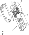
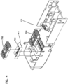
- Figures 1-4 show an optical interface unit in accordance with the principles of the present disclosure.
- the optical interface unit can be configured to provide a number of different functions.
- One example function relates to providing protection for locations in the field where the optical fibers of fiber optic cables (e.g., distribution cables, drop cables, etc.) are accessed.
- fiber optic cables can be routed into the optical interface unit and within the optical interface unit at least portions of the outer the outer jackets of the fiber optic cables can be removed (e.g., via window cuts or by ring cutting the jackets and stripping off portions of the jackets between the ring cuts) to expose the optical fibers for access within the optical interface unit.
- the optical interface unit is environmentally sealed to protect the optical fiber access locations.
- optical interface unit can include internal structure for making optical connections (e.g., optical splices such as optical fusion splices or mechanical splices, demateable connections such optical connections between optical connectors either through direct mating or via intermediate fiber optic adapters, or other connections) between optical fibers accessed in the field.
- optical connections e.g., optical splices such as optical fusion splices or mechanical splices, demateable connections such optical connections between optical connectors either through direct mating or via intermediate fiber optic adapters, or other connections
- a further example function relates to adding functionality in the field.
- the optical interface unit can house value-added optical components such as passive optical splitters (symmetric or asymmetric such as an optical tap), wavelength division multiplexers (coarse or fine), optical splices protected within splice reinforcing sleeves (e.g., heat shrink sleeves containing each containing a reinforcing rod and adhesive), fiber optic connectors, fiber optic adapters and the like.
- value added components can be secured to component holders that are secured within the optical interface unit (e.g., to trays, brackets, flanges, shelfs, panels, housing walls, housing covers, housing bases, or the like).
- the optical interface unit of Figures 1-14 include a telecommunications enclosure 100 having a housing 110 that is preferably environmentally sealed when closed.
- the housing 110 includes a base 113 and a cover 114.
- the cover 114 is movable between an open position and a closed position. As depicted, the cover 114 is attached to the base by a hinge that allows the cover to be pivoted relative to the base 113 between the open position and the closed position.
- An interior of the housing 110 is accessible when the cover is in the open position.
- Latches 115 can be used to retain the housing in the closed position.
- the enclosure includes a sealing arrangement 120 for environmentally sealing the housing 110 when the housing 110 is closed.
- the sealing arrangement 120 can include a perimeter seal 124 for sealing a perimeter interface between the cover 114 and the base, and a cable sealing unit 125 for sealing locations where cables enter/exit the housing.
- the optical interface unit also includes a management unit 130 that mounts within the housing.
- the management unit 130 includes a main frame/support infrastructure 133 having a front side 135 and a back side 131.
- the support infrastructure 133 includes a front cover 137 and an adapter mounting location 136 at the front side 135.
- Fiber optic adapters 150 are mounted at the adapter mounting location 136.
- Cable anchoring structures e.g., clamping locations, tie-down locations, etc.
- a rear fiber management tray 138 is pivotally mounted at the back side 131 of the support infrastructure 133.
- Support brackets 141 are also mounted at the back side 131.
- the support brackets 141 can be connected to side walls of the infrastructure 133 by a dove-tail interface 139 and a flexible retaining latch 143.
- Each of the brackets 141 can include a first connection interface arrangement 700 that is part of a mechanical connection interface 702 in accordance with the principles of the present disclosure.
- the mechanical connection interface 702 also includes a second connection interface arrangement 704 included as part of a component holder 706 adapted for holding optical components such as a splice reinforcing sleeves for protecting optical fusion splices, passive optical splitters or wavelength division multiplexers.
- the first and second connection arrangements 700, 704 are adapted to interlock to secure the component holder 706 to the bracket 141.
- the connection arrangements 700, 704 can be reversed so that the first connection arrangement 700 is on the component holder and the second connection arrangement 704 is on the bracket 141.
- the bracket is just one example of a type of structure to which a component holder can be secured using mechanical connection interfaces in accordance with the principles of the present disclosure.
- Other example structures include trays, flanges, shelfs, panels, housing walls, housing covers, housing bases, and the like.
- the first connection interface arrangement 700 defines first and second attachment openings 710a, 710b aligned along a first reference line 712.
- the first and second attachment openings 710a, 710b each defining a groove portion 714a, 714b and an enlarged portion 716a, 716b.
- the groove portions 714a, 714b have lengths that extend along the first reference line 712 and first widths W1 that extend perpendicular to the first reference line 712.
- the enlarged portions 716a, 716b define second widths W2 that are larger than the first widths W1 and that are perpendicular to the first reference line 712.
- the first connection interface arrangement 700 further includes a flexible cantilever latch 718 positioned within the enlarged portion 716a of the first attachment opening 710a.
- the flexible cantilever latch 718 has a length that extends along the first reference line 712 between a base end 720 and a free end 722 of the flexible cantilever latch 718.
- the enlarged portion 716a of the first attachment opening 710a includes an interlock receiving portion 724 defined between the free end 722 of the flexible cantilever latch 718 and the groove portion 714a of the first attachment opening 710a.
- the free end 722 of the flexible cantilever latch 718 defines a first stop surface 726.
- the groove portion 714b of the second attachment opening 710b has an end 728 positioned opposite from the enlarged portion 716b of the second attachment opening 710b which defines a second stop surface 730.
- a top side of the flexible cantilever latch 718 defines a stop receptacle 732 including a ramp surface 734.
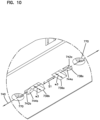
- the second connection interface arrangement 704 integrated with the component holder 706 includes a first interlock 736a, a second interlock 736b, a first stop 738a and a second stop 738b all aligned along a second reference line 740.
- the first and second interlocks 736a, 736b are positioned between the first and second stops 738a, 738b.
- the first and second stops 738a, 738b include stop surfaces 742a, 742b that face at least partially away from the first and second interlocks 736a, 736b.
- the first and second stops 738a, 738b have ramp surfaces 744a, 744b that face at least partially toward the first and second interlocks 736a, 736b.
- the first and second interlocks 736a, 736b define third widths W3 that are perpendicular to the second reference line 740.
- the third widths W3 are smaller than the second widths W2 of the enlarged portions 716a, 716b of the first and second attachment openings 710a, 710b.
- the third widths W3 are larger than the first widths W1 of the groove portions 714a, 714b of the first and second attachment openings 710a, 710b.
- the first and second interlocks 736a, 736b are separated by a spacing S1 ( Figure 10 ) along the second reference line 740 that corresponds to a spacing S2 ( Figure 5 ) between the enlarged portions 716a, 716b of the first and second attachment openings 710a, 710b along the first reference line 712.
- the second connection interface arrangement 704 is connected to the first connection interface arrangement 700 by orienting the second connection interface 704 arrangement in a first position relative to the first connection interface arrangement 700 (see Figure 11 ).
- the first and second connections interface arrangements 700, 704 are relatively positioned such that: a) the first and second reference axes 712, 740 are aligned; b) the first interlock 736a is received within interlock receiving portion 724 of the enlarged portion 716a of the first attachment opening 710a; c) the second interlock 736b is received within the enlarged portion 716b of the second attachment opening 710b; and d) the first stop 738a is positioned within the stop receptacle 732 of the of the flexible cantilever latch 718 with the ramp surface 744a of the first stop 738a opposing the ramp surface 734 of the stop receptacle 732.
- connection interface arrangement 704 is slid relative to the first connection interface arrangement 700 along the aligned first and second reference axes 712, 740 from the first position to a second position (see Figure 13 ).
- the first and second connection interface arrangements 700, 704 are relatively positioned such that: a) the first interlock 736a is received within and interlocked with the groove portion 714a of the first attachment opening 710a; b) the first stop 738a is positioned within the interlock receiving portion 724 of the enlarged portion 716a of the first attachment opening 710a with the stop surface 742a of the first stop 738a opposing the first stop surface 726 at the free end 722 of the flexible cantilever latch 718; c) the second stop 738b is positioned within the groove portion 714b of the second attachment opening 710b with the stop surface 742b of the second stop 738b opposing the second stop surface 730 at the end of the groove portion 714b of the second attachment opening 710b; and d) the second interlock 736b is received within and interlocked with the groove portion 714b of the second attachment opening 710b.
- the ramp surface 744a of the first stop 738a engages the ramp surface 734 of the stop receptacle 732 to cause deflection of the flexible cantilever latch 718 (see Figure 12 ) from a latching position to an unlatched position.
- the flexible cantilever latch 718 elastically returns from the unlatched position to the latching position.
- the groove portions 714a, 714b and the first and second interlocks 736a, 736b have dovetailed shapes in cross-sectional planes that are perpendicular to the first and second reference lines 712, 740 (see Figures 6 and 7 ).
- the stop surfaces 742a, 742b of the first and second stops 738a, 738b face at least partially in opposite directions.
- the ramp surfaces 744a, 744b of the first and second stops 738a, 738b face partially towards each other.
- the first and second stop surfaces 726, 730 of the first connection interface arrangement 700 face at least partially towards each other.
- the base end 720 of the flexible cantilever latch 718 is unitarily formed with the main body 749.
- the first and second attachment openings 710a, 710b extend through the first portion 750 of the main body 749 from the top side 752 to the bottom side 754.
- the stop receptacle 732 of the flexible cantilever latch 718 is defined at a top side 756 of the flexible cantilever latch 718 that is coplanar with the top side 752 of the first portion 750 of the main body 749 when the flexible cantilever latch 718 is in the latching position.
- the stop receptacle 732 extends downwardly into the flexible cantilever latch 718 from the top side 756 of the flexible cantilever latch 718 so that the stop receptacle 732 extends lower than the top side 752 of the first portion 750 of the main body 749 when the flexible cantilever latch 718 is in the latching position.
- the first connection interface arrangement 700 defines a first seating surface 760 (e.g., the top side 752 of the portion 750 of the main body 749) through which the first and second attachment openings 710a, 710b extend.
- the second connection interface arrangement 704 defines a second seating surface762 (e.g., the underside of the component holder 706) from which the first interlock 736a, the second interlock 736b, the first stop 738a and the second stop 738b project.
- the first and second seating surfaces 760, 762 are flush when the second connection interface arrangement 704 is in the first position relative to the first connection interface arrangement 700 and are also flush when the second connection interface arrangement 704 is in the second position relative to the first connection interface arrangement 700.
- the flexible cantilever latch 718 is in the latching position when the second connection interface arrangement 704 is in the first position relative to the first connection interface arrangement 700, and the flexible cantilever latch 718 is also in the latching position when the second connection interface arrangement 704 is in the second position relative to the first connection interface arrangement 700.
- Release openings 770 are defined through the first sealing surface 760 for allowing the cantilever 718 to be depressed with a tool such that the cantilever is moved to the non-latching position thereby allowing the second connection interface arrangement 704 to be disengaged from the first connection interface arrangement 700 by sliding the component holder 706 from the second position (see Figure 13 ) back to the first position (see Figure 11 ).
- Figure 14 shows the first connection interface arrangement 700 integrated into a fiber management tray 780 so that the component holder 706 including the second connection interface arrangement 704 can be readily coupled to the fiber management tray 780 by the mechanical connection interface 702.
Landscapes
- Physics & Mathematics (AREA)
- General Physics & Mathematics (AREA)
- Optics & Photonics (AREA)
- Light Guides In General And Applications Therefor (AREA)
Claims (12)
- Mechanische Verbindungsschnittstelle (702) zum Verbinden und Lösen von optischen Komponenten, wobei die mechanische Verbindungsschnittstelle (702) umfasst:eine erste Verbindungsschnittstellenanordnung (700), die eine Befestigungsöffnung (710a) definiert, die einen Nutabschnitt (714a) und einen vergrößerten Abschnitt (716a) definiert, wobei der Nutabschnitt (714a) eine Länge aufweist, die sich entlang einer ersten Referenzlinie (712) und einer ersten Breite (W1) erstreckt, die sich senkrecht zu der ersten Referenzlinie (712) erstreckt, der vergrößerte Abschnitt (716a) eine zweite Breite (W2) senkrecht zu der ersten Referenzlinie (712) definiert, die größer ist als die erste Breite (W1), die erste Verbindungsschnittstellenanordnung (700) ferner eine flexible Auslegerklinke (718) umfasst, die innerhalb des vergrößerten Abschnitts (716a) der Befestigungsöffnung (710a) positioniert ist, die flexible Auslegerklinke (718) eine Länge aufweist, die sich entlang der ersten Referenzlinie (712) erstreckt, die flexible Auslegerklinke (718) ein Basisende (720) und ein freies Ende (722) umfasst, der vergrößerte Abschnitt (716a) der Befestigungsöffnung (710a) einen Verriegelungsaufnahmeabschnitt (724) umfasst, der zwischen dem freien Ende (722) der flexiblen Auslegerklinke (718) und dem Nutabschnitt (714a) der Befestigungsöffnung (710a) definiert ist, das freie Ende (722) der flexiblen Auslegerklinke (718) eine Anschlagfläche (726) definiert und die flexible Auslegerklinke (718) eine Anschlagaufnahme (732) definiert;eine zweite Verbindungsschnittstellenanordnung (704), die konfiguriert ist, mit der ersten Verbindungsschnittstellenanordnung (700) zu verriegeln, wobei die zweite Verbindungsschnittstellenanordnung (704) eine Verriegelung (736a) und einen Anschlag (738a) umfasst, die entlang einer zweiten Referenzlinie (740) ausgerichtet sind, der Anschlag (738a) eine Anschlagfläche (742a) umfasst, die Verriegelung (736a) eine dritte Breite (W3) definiert, die sich senkrecht zu der zweiten Referenzlinie (740) erstreckt, und die dritte Breite (W3) kleiner ist als die zweite Breite (W2) und größer als die erste Breite (W1);wobei mindestens eines von der Anschlagaufnahme (732) und/oder dem Anschlag (738a) eine Rampenfläche (734, 744a) umfasst;wobei die zweite Verbindungsschnittstellenanordnung (704) konfiguriert ist, durch Ausrichten der zweiten Verbindungsschnittstellenanordnung (704) in einer ersten Position relativ zu der ersten Verbindungsschnittstellenanordnung (700) mit der ersten Verbindungsschnittstellenanordnung (700) verbunden zu werden, wobei: a) die erste und die zweite Referenzachse (712, 740) ausgerichtet sind; b) die Verriegelung (736a) innerhalb des Verriegelungsaufnahmeabschnitts (724) des vergrößerten Abschnitts (716a) der Befestigungsöffnung (710a) aufgenommen ist; und c) der Anschlag (738a) innerhalb der Anschlagaufnahme (732) der flexiblen Auslegerklinke (718) positioniert ist; und dann das Verschieben der zweiten Verbindungsschnittstellenanordnung (704) entlang der ausgerichteten ersten und zweiten Referenzachse (712, 740) von der ersten Position zu einer zweiten Position, wobei: a) die Verriegelung (736a) in dem Nutabschnitt (714a) der Befestigungsöffnung (710a) aufgenommen und damit verriegelt ist; und b) der Anschlag (738a) innerhalb des Verriegelungsaufnahmeabschnitts (724) des vergrößerten Abschnitts (716a) der Befestigungsöffnung (710a) positioniert ist, wobei die Anschlagfläche (742a) des Anschlags (738a) der Anschlagfläche (726) am freien Ende (722) der flexiblen Auslegerklinke (718) gegenüberliegt; undwobei, während die zweite Verbindungsschnittstellenanordnung (704) von der ersten Position in die zweite Position verschoben wird, die Rampenfläche (734, 744a) bewirkt, dass sich die flexible Auslegerklinke (718) aus einer Verriegelungsposition in eine entriegelte Position auslenkt, und wobei, nachdem sich der Anschlag (738a) an dem freien Ende der flexiblen Auslegerklinke (718) vorbei bewegt, die flexible Auslegerklinke (718) von der entriegelten Position in die Verriegelungsposition elastisch zurückkehrt;wobei die erste Verbindungsschnittstellenanordnung (700) eine erste Auflagefläche (760) umfasst, durch die sich die Befestigungsöffnung (710a) erstreckt, wobei die zweite Verbindungsschnittstellenanordnung (704) eine zweite Auflagefläche (762) definiert, von der die Verriegelung (736a) und der Anschlag (738a) vorstehen, wobei die erste und die zweite Auflagefläche (760, 762) fluchten, wenn sich die zweite Verbindungsschnittstellenanordnung (704) in der ersten Position relativ zu der ersten Verbindungsschnittstellenanordnung (700) befindet, und auch fluchtet, wenn sich die zweite Verbindungsschnittstellenanordnung (704) in der zweiten Position relativ zu der ersten Verbindungsschnittstellenanordnung (700) befindet, wobei sich die flexible Auslegerklinke (718) in der Verriegelungsposition befindet, wenn sich die zweite Verbindungsschnittstellenanordnung (704) in der ersten Position relativ zu der ersten Verbindungsschnittstellenanordnung (700) befindet, und wobei sich die flexible Auslegerklinke (718) in der Verriegelungsposition befindet, wenn sich die zweite Verbindungsschnittstellenanordnung (704) in der zweiten Position relativ zu der ersten Verbindungsschnittstellenanordnung (700) befindet.
- Mechanische Verbindungsschnittstelle (702) nach Anspruch 1, wobei die erste Verbindungsschnittstellenanordnung (700) in eine Telekommunikationskomponente integriert ist.
- Mechanische Verbindungsschnittstelle (702) nach Anspruch 2, wobei die Telekommunikationskomponente eine Struktur umfasst, die zur Verwaltung von Lichtwellenleitern angepasst ist.
- Mechanische Verbindungsschnittstelle (702) nach Anspruch 3, wobei die Telekommunikationskomponente eine Wanne ist.
- Mechanische Verbindungsschnittstelle (702) nach Anspruch 3, wobei die Telekommunikationskomponente eine Halterung (141) ist.
- Mechanische Verbindungsschnittstelle (702) nach Anspruch 1, wobei die zweite Verbindungsschnittstellenanordnung (704) in einen Halter (706) integriert ist, der zur Aufnahme einer mit Lichtwellenleitern gekoppelten Lichtwellenleiterkomponente geeignet ist.
- Mechanische Verbindungsschnittstelle (702) nach Anspruch 6, wobei die Lichtwellenleiterkomponente ein Spleißschutz, ein passiver optischer Leistungsteiler oder ein Wellenlängenmultiplexer ist.
- Mechanische Verbindungsschnittstelle (702) nach Anspruch 1, wobei der Nutabschnitt (714a) und die Verriegelung (736a) schwalbenschwanzförmige Formen in Querschnittsebenen aufweisen, die senkrecht zu der ersten und der zweiten Referenzlinie (712, 740) verlaufen.
- Mechanische Verbindungsschnittstelle (702) nach Anspruch 2, wobei ein Hauptkörper (749) der Telekommunikationskomponente einen ersten Abschnitt (750) mit einer Oberseite (752) und einer Unterseite (754) umfasst, wobei sich die Befestigungsöffnung (710a) von der Oberseite (752) zu der Unterseite (754) durch den ersten Abschnitt (750) des Hauptkörpers (749) erstreckt, wobei das Basisende (720) der flexiblen Auslegerklinke (718) mit dem Hauptkörper (749) einstückig gebildet ist, und wobei die Anschlagaufnahme (732) der flexiblen Auslegerklinke (718) an einer Oberseite (756) der flexiblen Auslegerklinke (718) definiert ist, die mit der Oberseite (752) des ersten Abschnitts (750) des Hauptkörpers (749) koplanar ist, wenn sich die flexible Auslegerklinke (718) in der Verriegelungsposition befindet, und wobei sich die Anschlagaufnahme (732) von der Oberseite (756) der flexiblen Auslegerklinke (718) nach unten in die flexible Auslegerklinke (718) erstreckt, sodass sich die Anschlagaufnahme (732) niedriger als die obere Fläche (752) des ersten Abschnitts (750) des Hauptkörpers (749) erstreckt, wenn sich die flexible Auslegerklinke (718) in der Verriegelungsposition befindet.
- Mechanische Verbindungsschnittstelle (702) nach Anspruch 1, wobei die Anschlagaufnahme (732) und der Anschlag (738a) Rampenflächen (734, 744a) umfassen, wobei die Rampenfläche (744a) des Anschlags (738a) der Rampenfläche (734) der Anschlagaufnahme (732) gegenüberliegt, wenn sich die zweite Verbindungsschnittstellenanordnung (704) in der ersten Position relativ zu der ersten Verbindungsschnittstellenanordnung (700) befindet, und wobei die Rampenflächen (734, 744a) ineinandergreifen, während die zweite Verbindungsschnittstellenanordnung (704) von der ersten Position in die zweite Position relativ zu der ersten Verbindungsschnittstellenanordnung (700) bewegt wird, um eine Auslenkung der flexiblen Auslegerklinke (718) von einer Verriegelungsposition in eine entriegelte Position zu bewirken.
- Mechanische Verbindungsschnittstelle (702) nach Anspruch 1, wobei die Befestigungsöffnung (710a) eine erste Befestigungsöffnung (710a) ist, die Verriegelung (736a) eine erste Verriegelung (736a) ist und der Anschlag (738a) ein erster Anschlag (738a) ist, wobei die erste Verbindungsschnittstellenanordnung (700) ferner eine zweite Befestigungsöffnung (710b) umfasst, die entlang der ersten Referenzlinie (712) ausgerichtet ist, wobei die zweite Befestigungsöffnung (710b) einen vergrößerten Abschnitt (716b) und einen Nutabschnitt (714b) umfasst, wobei die zweite Verbindungsschnittstellenanordnung (704) ferner eine zweite Verriegelung (736b) und einen zweiten Anschlag (738b) umfasst, die entlang der zweiten Referenzlinie (740) ausgerichtet sind, wobei sich die erste und die zweite Verriegelung (736a, 736b) zwischen dem ersten und dem zweiten Anschlag (738a, 738b) befinden, wobei die zweite Verriegelung (736b) in den vergrößerten Abschnitt (716b) der zweiten Befestigungsöffnung (710b) passt, wenn sich die zweite Verbindungsschnittstellenanordnung (704) in der ersten Position relativ zu der ersten Verbindungsschnittstellenanordnung (700) befindet, wobei die zweite Verriegelung (736b) in den Nutabschnitt (714b) der zweiten Befestigungsöffnung (710b) passt, wenn sich die zweite Verbindungsschnittstellenanordnung (704) in der zweiten Position relativ zu der ersten Verbindungsschnittstellenanordnung (700) befindet, und wobei der zweite Anschlag (738b) einem geschlossenen Ende des Nutabschnitts (714b) der zweiten Befestigungsöffnung (710b) gegenüberliegt, wenn sich die zweite Verbindungsschnittstellenanordnung (704) in der zweiten Position relativ zu der ersten Verbindungsschnittstellenanordnung (700) befindet.
- Mechanische Verbindungsschnittstelle (702) nach Anspruch 1, wobei die zweite Verbindungsschnittstellenanordnung (704) eine Verriegelungsfreigabeöffnung (770) definiert, die mit der flexiblen Auslegerklinke (718) ausgerichtet ist, wenn sich die zweite Verbindungsschnittstellenanordnung (704) in der zweiten Position relativ zu der ersten Verbindungsschnittstellenanordnung (700) befindet.
Applications Claiming Priority (2)
| Application Number | Priority Date | Filing Date | Title |
|---|---|---|---|
| US201862661437P | 2018-04-23 | 2018-04-23 | |
| PCT/US2019/028245 WO2019209643A1 (en) | 2018-04-23 | 2019-04-19 | Mechanical connection interface for a telecommunications component |
Publications (3)
| Publication Number | Publication Date |
|---|---|
| EP3785057A1 EP3785057A1 (de) | 2021-03-03 |
| EP3785057A4 EP3785057A4 (de) | 2022-01-12 |
| EP3785057B1 true EP3785057B1 (de) | 2023-09-13 |
Family
ID=68294228
Family Applications (1)
| Application Number | Title | Priority Date | Filing Date |
|---|---|---|---|
| EP19793744.4A Active EP3785057B1 (de) | 2018-04-23 | 2019-04-19 | Mechanische verbindungsschnittstelle für eine optische telekommunikationskomponente |
Country Status (3)
| Country | Link |
|---|---|
| US (1) | US11402589B2 (de) |
| EP (1) | EP3785057B1 (de) |
| WO (1) | WO2019209643A1 (de) |
Families Citing this family (11)
| Publication number | Priority date | Publication date | Assignee | Title |
|---|---|---|---|---|
| PT3776044T (pt) | 2018-04-12 | 2024-05-13 | CommScope Connectivity Belgium BVBA | Configurações de caixas para cabos de fibra ótica |
| WO2019212887A1 (en) | 2018-05-01 | 2019-11-07 | Commscope Technologies Llc | Tray tower with position indexing trays |
| PL3948376T3 (pl) | 2019-03-27 | 2026-02-16 | Commscope Technologies Llc | Uchwyt adaptera światłowodowego, zespół oraz sposób |
| US12210203B2 (en) | 2019-03-29 | 2025-01-28 | Commscope Technologies Llc | Tray hinge interface system with opposing recessed surfaces recessed toward the pivot axis |
| EP3977191A4 (de) | 2019-05-31 | 2023-06-28 | CommScope Technologies LLC | Glasfaserkabelspeichervorrichtungen, systeme und verfahren |
| MX2022001056A (es) | 2019-07-26 | 2022-02-14 | Commscope Technologies Llc | Bandejas de gestion de cables de fibra optica; montajes; y metodos. |
| WO2021243277A1 (en) | 2020-05-29 | 2021-12-02 | Commscope Technologies Llc | Fiber management tray arrangements and assemblies for fiber optic closure organizers |
| WO2022192670A1 (en) * | 2021-03-12 | 2022-09-15 | Commscope Technologies Llc | Components for fiber optic systems |
| US11927808B2 (en) * | 2021-04-16 | 2024-03-12 | Commscope Technologies Llc | Holder for an optical component |
| CA3219544A1 (en) | 2021-05-19 | 2022-11-24 | Christopher Grubish | Cable restraints for splice enclosures and splice enclosures including cable restraints |
| EP4508473A1 (de) * | 2022-04-14 | 2025-02-19 | CommScope Technologies LLC | Halterung für ein optisches bauteil |
Family Cites Families (22)
| Publication number | Priority date | Publication date | Assignee | Title |
|---|---|---|---|---|
| US5337211A (en) | 1993-06-14 | 1994-08-09 | Eaton Corporation | Electrical load center interior panel having molded insulating support panel with snap-in bus bars |
| PL182960B1 (pl) * | 1996-02-29 | 2002-05-31 | Raychem Sa Nv | Urządzenie do rozprowadzania i magazynowania włókien światłowodowych |
| JP2003329873A (ja) * | 2001-12-27 | 2003-11-19 | Fujikura Ltd | 位置決め機構を備えた光ファイバ把持具、光ファイバアダプタ、及び光ファイバ加工装置 |
| US6944389B2 (en) * | 2003-11-26 | 2005-09-13 | Corning Cable Systems Llc | Connector housing having a sliding tray with a hingeable portion |
| US7441374B2 (en) * | 2005-06-30 | 2008-10-28 | Hi-Lex Corporation | Door module plate with handle |
| US7272291B2 (en) * | 2005-08-25 | 2007-09-18 | Adc Telecommunications, Inc. | Splice chip device |
| US7310471B2 (en) * | 2005-08-25 | 2007-12-18 | Adc Telecommunications, Inc. | Stackable splice chip device |
| US7330629B2 (en) * | 2005-08-31 | 2008-02-12 | Corning Cable Systems Llc | Fiber optic universal bracket apparatus and methods |
| US7664360B2 (en) | 2007-04-17 | 2010-02-16 | Corning Cable Systems Llc | Fiber optic drop terminal mounting plate |
| US8123185B2 (en) * | 2008-03-24 | 2012-02-28 | Ss3 Storage Systems, L.L.C. | Bracket release mechanism |
| US8285104B2 (en) * | 2008-08-29 | 2012-10-09 | Corning Cable Systems Llc | Clip for securing a fiber optic cable assembly and associated assemblies |
| US7945136B2 (en) * | 2009-06-19 | 2011-05-17 | Corning Cable Systems Llc | Mounting of fiber optic cable assemblies within fiber optic shelf assemblies |
| US8538227B2 (en) * | 2010-05-14 | 2013-09-17 | Corning Cable Systems Llc | Furcation management structures |
| CN105068204B (zh) * | 2011-10-07 | 2018-08-10 | Adc电信公司 | 带有缆线松弛管理的可滑动光纤连接模块 |
| US8559784B2 (en) * | 2011-10-26 | 2013-10-15 | All Systems Broadband, Inc. | Modular assembly for supporting fiber optic splices |
| US9348105B2 (en) * | 2012-05-25 | 2016-05-24 | Commscope Technologies Llc | Splice chips for optical fiber splice cassettes |
| US9042702B2 (en) | 2012-09-18 | 2015-05-26 | Corning Cable Systems Llc | Platforms and systems for fiber optic cable attachment |
| AP2015008820A0 (en) * | 2013-04-24 | 2015-10-31 | Adc Czech Republic Sro | Optical fiber distribution system |
| WO2016094292A1 (en) | 2014-12-09 | 2016-06-16 | Commscope Technologies Llc | Releasable connection interface for a fiber optic component holder |
| WO2017114936A1 (en) * | 2015-12-31 | 2017-07-06 | CommScope Connectivity Belgium BVBA | Cable fixation devices and methods |
| US11422327B2 (en) | 2018-02-13 | 2022-08-23 | Commscope Technologies Llc | Cable sealant arrangement for a sealed closure |
| EP3745177A1 (de) * | 2019-05-29 | 2020-12-02 | CommScope Technologies LLC | Adapter für faseroptischen halter, anordnung und verfahren |
-
2019
- 2019-04-19 EP EP19793744.4A patent/EP3785057B1/de active Active
- 2019-04-19 WO PCT/US2019/028245 patent/WO2019209643A1/en not_active Ceased
- 2019-04-19 US US17/049,924 patent/US11402589B2/en active Active
Also Published As
| Publication number | Publication date |
|---|---|
| EP3785057A1 (de) | 2021-03-03 |
| EP3785057A4 (de) | 2022-01-12 |
| US20210239917A1 (en) | 2021-08-05 |
| US11402589B2 (en) | 2022-08-02 |
| WO2019209643A1 (en) | 2019-10-31 |
Similar Documents
| Publication | Publication Date | Title |
|---|---|---|
| EP3785057B1 (de) | Mechanische verbindungsschnittstelle für eine optische telekommunikationskomponente | |
| EP2266377B1 (de) | Rückwärtige verriegelungsanordnung für ausziehbare schublade | |
| EP1621907B1 (de) | Verteilerkasten für optisches Kommunikationsnetzwerk | |
| US9684143B2 (en) | Releasable connection interface for a fiber optic component holder | |
| EP3132298B1 (de) | Glasfasergehäuse mit kabelverwaltungsschublade | |
| US6944389B2 (en) | Connector housing having a sliding tray with a hingeable portion | |
| US7245809B1 (en) | Splitter modules for fiber distribution hubs | |
| US8019191B2 (en) | Method and device for coupling optical waveguides | |
| CN102884463B (zh) | 装置和相关的组件以及用于扩大光学纤维罩壳的容量的方法 | |
| US12392978B2 (en) | Telecommunication enclosure | |
| CN104704411A (zh) | 光纤分配箱 | |
| CN102884465A (zh) | 用于光学纤维罩壳的可移除纤维管理器件,以及相关的组件和方法 | |
| WO2021087278A1 (en) | Telecommunication enclosure | |
| HK1231565A1 (zh) | 可枢转地附接的光纤外壳、模块化外壳系统和方法 | |
| EP4030212B1 (de) | Verbindungskabelkasten | |
| CN101163998A (zh) | 光纤配线板中的可移动停靠插头 | |
| EP4423554A1 (de) | Anordnung mit einem integrierten faserschleifenspeicherkorb für eine glasfaserverwaltungsanordnung | |
| HK1151938B (en) | Rear latch arrangement for sliding drawer | |
| CN102884466A (zh) | 用于光学纤维罩壳的门纤维管理,以及相关的组件和方法 |
Legal Events
| Date | Code | Title | Description |
|---|---|---|---|
| STAA | Information on the status of an ep patent application or granted ep patent |
Free format text: STATUS: THE INTERNATIONAL PUBLICATION HAS BEEN MADE |
|
| PUAI | Public reference made under article 153(3) epc to a published international application that has entered the european phase |
Free format text: ORIGINAL CODE: 0009012 |
|
| STAA | Information on the status of an ep patent application or granted ep patent |
Free format text: STATUS: REQUEST FOR EXAMINATION WAS MADE |
|
| 17P | Request for examination filed |
Effective date: 20201015 |
|
| AK | Designated contracting states |
Kind code of ref document: A1 Designated state(s): AL AT BE BG CH CY CZ DE DK EE ES FI FR GB GR HR HU IE IS IT LI LT LU LV MC MK MT NL NO PL PT RO RS SE SI SK SM TR |
|
| AX | Request for extension of the european patent |
Extension state: BA ME |
|
| DAV | Request for validation of the european patent (deleted) | ||
| DAX | Request for extension of the european patent (deleted) | ||
| RIN1 | Information on inventor provided before grant (corrected) |
Inventor name: CLAESSENS, BART MATTIE Inventor name: ALAERTS, ROGER JOSEPH Inventor name: CARRICO, WILLIAM ALAN Inventor name: VERSLEEGERS, JOZEF CHRISTIAAN MATHIEU Inventor name: BERVOETS, MARC EUGENE WILLEM |
|
| A4 | Supplementary search report drawn up and despatched |
Effective date: 20211215 |
|
| RIC1 | Information provided on ipc code assigned before grant |
Ipc: F16B 21/09 20060101ALN20211209BHEP Ipc: F16B 5/06 20060101ALN20211209BHEP Ipc: G02B 6/44 20060101AFI20211209BHEP |
|
| RIC1 | Information provided on ipc code assigned before grant |
Ipc: G02B 6/38 20060101ALN20230221BHEP Ipc: F16B 21/09 20060101ALN20230221BHEP Ipc: F16B 5/06 20060101ALN20230221BHEP Ipc: G02B 6/44 20060101AFI20230221BHEP |
|
| GRAP | Despatch of communication of intention to grant a patent |
Free format text: ORIGINAL CODE: EPIDOSNIGR1 |
|
| STAA | Information on the status of an ep patent application or granted ep patent |
Free format text: STATUS: GRANT OF PATENT IS INTENDED |
|
| RIC1 | Information provided on ipc code assigned before grant |
Ipc: G02B 6/38 20060101ALN20230317BHEP Ipc: F16B 21/09 20060101ALN20230317BHEP Ipc: F16B 5/06 20060101ALN20230317BHEP Ipc: G02B 6/44 20060101AFI20230317BHEP |
|
| INTG | Intention to grant announced |
Effective date: 20230405 |
|
| GRAS | Grant fee paid |
Free format text: ORIGINAL CODE: EPIDOSNIGR3 |
|
| GRAA | (expected) grant |
Free format text: ORIGINAL CODE: 0009210 |
|
| STAA | Information on the status of an ep patent application or granted ep patent |
Free format text: STATUS: THE PATENT HAS BEEN GRANTED |
|
| AK | Designated contracting states |
Kind code of ref document: B1 Designated state(s): AL AT BE BG CH CY CZ DE DK EE ES FI FR GB GR HR HU IE IS IT LI LT LU LV MC MK MT NL NO PL PT RO RS SE SI SK SM TR |
|
| REG | Reference to a national code |
Ref country code: CH Ref legal event code: EP |
|
| REG | Reference to a national code |
Ref country code: DE Ref legal event code: R096 Ref document number: 602019037468 Country of ref document: DE |
|
| REG | Reference to a national code |
Ref country code: IE Ref legal event code: FG4D |
|
| REG | Reference to a national code |
Ref country code: LT Ref legal event code: MG9D |
|
| REG | Reference to a national code |
Ref country code: NL Ref legal event code: MP Effective date: 20230913 |
|
| PG25 | Lapsed in a contracting state [announced via postgrant information from national office to epo] |
Ref country code: GR Free format text: LAPSE BECAUSE OF FAILURE TO SUBMIT A TRANSLATION OF THE DESCRIPTION OR TO PAY THE FEE WITHIN THE PRESCRIBED TIME-LIMIT Effective date: 20231214 |
|
| PG25 | Lapsed in a contracting state [announced via postgrant information from national office to epo] |
Ref country code: SE Free format text: LAPSE BECAUSE OF FAILURE TO SUBMIT A TRANSLATION OF THE DESCRIPTION OR TO PAY THE FEE WITHIN THE PRESCRIBED TIME-LIMIT Effective date: 20230913 Ref country code: RS Free format text: LAPSE BECAUSE OF FAILURE TO SUBMIT A TRANSLATION OF THE DESCRIPTION OR TO PAY THE FEE WITHIN THE PRESCRIBED TIME-LIMIT Effective date: 20230913 Ref country code: NO Free format text: LAPSE BECAUSE OF FAILURE TO SUBMIT A TRANSLATION OF THE DESCRIPTION OR TO PAY THE FEE WITHIN THE PRESCRIBED TIME-LIMIT Effective date: 20231213 Ref country code: LV Free format text: LAPSE BECAUSE OF FAILURE TO SUBMIT A TRANSLATION OF THE DESCRIPTION OR TO PAY THE FEE WITHIN THE PRESCRIBED TIME-LIMIT Effective date: 20230913 Ref country code: LT Free format text: LAPSE BECAUSE OF FAILURE TO SUBMIT A TRANSLATION OF THE DESCRIPTION OR TO PAY THE FEE WITHIN THE PRESCRIBED TIME-LIMIT Effective date: 20230913 Ref country code: HR Free format text: LAPSE BECAUSE OF FAILURE TO SUBMIT A TRANSLATION OF THE DESCRIPTION OR TO PAY THE FEE WITHIN THE PRESCRIBED TIME-LIMIT Effective date: 20230913 Ref country code: GR Free format text: LAPSE BECAUSE OF FAILURE TO SUBMIT A TRANSLATION OF THE DESCRIPTION OR TO PAY THE FEE WITHIN THE PRESCRIBED TIME-LIMIT Effective date: 20231214 Ref country code: FI Free format text: LAPSE BECAUSE OF FAILURE TO SUBMIT A TRANSLATION OF THE DESCRIPTION OR TO PAY THE FEE WITHIN THE PRESCRIBED TIME-LIMIT Effective date: 20230913 |
|
| REG | Reference to a national code |
Ref country code: AT Ref legal event code: MK05 Ref document number: 1611847 Country of ref document: AT Kind code of ref document: T Effective date: 20230913 |
|
| PG25 | Lapsed in a contracting state [announced via postgrant information from national office to epo] |
Ref country code: NL Free format text: LAPSE BECAUSE OF FAILURE TO SUBMIT A TRANSLATION OF THE DESCRIPTION OR TO PAY THE FEE WITHIN THE PRESCRIBED TIME-LIMIT Effective date: 20230913 |
|
| PG25 | Lapsed in a contracting state [announced via postgrant information from national office to epo] |
Ref country code: IS Free format text: LAPSE BECAUSE OF FAILURE TO SUBMIT A TRANSLATION OF THE DESCRIPTION OR TO PAY THE FEE WITHIN THE PRESCRIBED TIME-LIMIT Effective date: 20240113 |
|
| PG25 | Lapsed in a contracting state [announced via postgrant information from national office to epo] |
Ref country code: AT Free format text: LAPSE BECAUSE OF FAILURE TO SUBMIT A TRANSLATION OF THE DESCRIPTION OR TO PAY THE FEE WITHIN THE PRESCRIBED TIME-LIMIT Effective date: 20230913 |
|
| PG25 | Lapsed in a contracting state [announced via postgrant information from national office to epo] |
Ref country code: ES Free format text: LAPSE BECAUSE OF FAILURE TO SUBMIT A TRANSLATION OF THE DESCRIPTION OR TO PAY THE FEE WITHIN THE PRESCRIBED TIME-LIMIT Effective date: 20230913 |
|
| PG25 | Lapsed in a contracting state [announced via postgrant information from national office to epo] |
Ref country code: SM Free format text: LAPSE BECAUSE OF FAILURE TO SUBMIT A TRANSLATION OF THE DESCRIPTION OR TO PAY THE FEE WITHIN THE PRESCRIBED TIME-LIMIT Effective date: 20230913 Ref country code: RO Free format text: LAPSE BECAUSE OF FAILURE TO SUBMIT A TRANSLATION OF THE DESCRIPTION OR TO PAY THE FEE WITHIN THE PRESCRIBED TIME-LIMIT Effective date: 20230913 Ref country code: IS Free format text: LAPSE BECAUSE OF FAILURE TO SUBMIT A TRANSLATION OF THE DESCRIPTION OR TO PAY THE FEE WITHIN THE PRESCRIBED TIME-LIMIT Effective date: 20240113 Ref country code: ES Free format text: LAPSE BECAUSE OF FAILURE TO SUBMIT A TRANSLATION OF THE DESCRIPTION OR TO PAY THE FEE WITHIN THE PRESCRIBED TIME-LIMIT Effective date: 20230913 Ref country code: EE Free format text: LAPSE BECAUSE OF FAILURE TO SUBMIT A TRANSLATION OF THE DESCRIPTION OR TO PAY THE FEE WITHIN THE PRESCRIBED TIME-LIMIT Effective date: 20230913 Ref country code: CZ Free format text: LAPSE BECAUSE OF FAILURE TO SUBMIT A TRANSLATION OF THE DESCRIPTION OR TO PAY THE FEE WITHIN THE PRESCRIBED TIME-LIMIT Effective date: 20230913 Ref country code: AT Free format text: LAPSE BECAUSE OF FAILURE TO SUBMIT A TRANSLATION OF THE DESCRIPTION OR TO PAY THE FEE WITHIN THE PRESCRIBED TIME-LIMIT Effective date: 20230913 Ref country code: SK Free format text: LAPSE BECAUSE OF FAILURE TO SUBMIT A TRANSLATION OF THE DESCRIPTION OR TO PAY THE FEE WITHIN THE PRESCRIBED TIME-LIMIT Effective date: 20230913 Ref country code: PT Free format text: LAPSE BECAUSE OF FAILURE TO SUBMIT A TRANSLATION OF THE DESCRIPTION OR TO PAY THE FEE WITHIN THE PRESCRIBED TIME-LIMIT Effective date: 20240115 |
|
| PG25 | Lapsed in a contracting state [announced via postgrant information from national office to epo] |
Ref country code: PL Free format text: LAPSE BECAUSE OF FAILURE TO SUBMIT A TRANSLATION OF THE DESCRIPTION OR TO PAY THE FEE WITHIN THE PRESCRIBED TIME-LIMIT Effective date: 20230913 Ref country code: IT Free format text: LAPSE BECAUSE OF FAILURE TO SUBMIT A TRANSLATION OF THE DESCRIPTION OR TO PAY THE FEE WITHIN THE PRESCRIBED TIME-LIMIT Effective date: 20230913 |
|
| REG | Reference to a national code |
Ref country code: DE Ref legal event code: R097 Ref document number: 602019037468 Country of ref document: DE |
|
| P01 | Opt-out of the competence of the unified patent court (upc) registered |
Effective date: 20240525 |
|
| PG25 | Lapsed in a contracting state [announced via postgrant information from national office to epo] |
Ref country code: DK Free format text: LAPSE BECAUSE OF FAILURE TO SUBMIT A TRANSLATION OF THE DESCRIPTION OR TO PAY THE FEE WITHIN THE PRESCRIBED TIME-LIMIT Effective date: 20230913 |
|
| PLBE | No opposition filed within time limit |
Free format text: ORIGINAL CODE: 0009261 |
|
| STAA | Information on the status of an ep patent application or granted ep patent |
Free format text: STATUS: NO OPPOSITION FILED WITHIN TIME LIMIT |
|
| PG25 | Lapsed in a contracting state [announced via postgrant information from national office to epo] |
Ref country code: DK Free format text: LAPSE BECAUSE OF FAILURE TO SUBMIT A TRANSLATION OF THE DESCRIPTION OR TO PAY THE FEE WITHIN THE PRESCRIBED TIME-LIMIT Effective date: 20230913 |
|
| 26N | No opposition filed |
Effective date: 20240614 |
|
| PG25 | Lapsed in a contracting state [announced via postgrant information from national office to epo] |
Ref country code: SI Free format text: LAPSE BECAUSE OF FAILURE TO SUBMIT A TRANSLATION OF THE DESCRIPTION OR TO PAY THE FEE WITHIN THE PRESCRIBED TIME-LIMIT Effective date: 20230913 |
|
| PG25 | Lapsed in a contracting state [announced via postgrant information from national office to epo] |
Ref country code: SI Free format text: LAPSE BECAUSE OF FAILURE TO SUBMIT A TRANSLATION OF THE DESCRIPTION OR TO PAY THE FEE WITHIN THE PRESCRIBED TIME-LIMIT Effective date: 20230913 |
|
| PG25 | Lapsed in a contracting state [announced via postgrant information from national office to epo] |
Ref country code: BG Free format text: LAPSE BECAUSE OF FAILURE TO SUBMIT A TRANSLATION OF THE DESCRIPTION OR TO PAY THE FEE WITHIN THE PRESCRIBED TIME-LIMIT Effective date: 20230913 |
|
| PG25 | Lapsed in a contracting state [announced via postgrant information from national office to epo] |
Ref country code: MC Free format text: LAPSE BECAUSE OF FAILURE TO SUBMIT A TRANSLATION OF THE DESCRIPTION OR TO PAY THE FEE WITHIN THE PRESCRIBED TIME-LIMIT Effective date: 20230913 |
|
| PG25 | Lapsed in a contracting state [announced via postgrant information from national office to epo] |
Ref country code: MC Free format text: LAPSE BECAUSE OF FAILURE TO SUBMIT A TRANSLATION OF THE DESCRIPTION OR TO PAY THE FEE WITHIN THE PRESCRIBED TIME-LIMIT Effective date: 20230913 Ref country code: BG Free format text: LAPSE BECAUSE OF FAILURE TO SUBMIT A TRANSLATION OF THE DESCRIPTION OR TO PAY THE FEE WITHIN THE PRESCRIBED TIME-LIMIT Effective date: 20230913 |
|
| REG | Reference to a national code |
Ref country code: CH Ref legal event code: PL |
|
| PG25 | Lapsed in a contracting state [announced via postgrant information from national office to epo] |
Ref country code: LU Free format text: LAPSE BECAUSE OF NON-PAYMENT OF DUE FEES Effective date: 20240419 |
|
| REG | Reference to a national code |
Ref country code: BE Ref legal event code: MM Effective date: 20240430 |
|
| PG25 | Lapsed in a contracting state [announced via postgrant information from national office to epo] |
Ref country code: LU Free format text: LAPSE BECAUSE OF NON-PAYMENT OF DUE FEES Effective date: 20240419 |
|
| PG25 | Lapsed in a contracting state [announced via postgrant information from national office to epo] |
Ref country code: BE Free format text: LAPSE BECAUSE OF NON-PAYMENT OF DUE FEES Effective date: 20240430 |
|
| PG25 | Lapsed in a contracting state [announced via postgrant information from national office to epo] |
Ref country code: BE Free format text: LAPSE BECAUSE OF NON-PAYMENT OF DUE FEES Effective date: 20240430 Ref country code: CH Free format text: LAPSE BECAUSE OF NON-PAYMENT OF DUE FEES Effective date: 20240430 |
|
| PG25 | Lapsed in a contracting state [announced via postgrant information from national office to epo] |
Ref country code: IE Free format text: LAPSE BECAUSE OF NON-PAYMENT OF DUE FEES Effective date: 20240419 |
|
| PGFP | Annual fee paid to national office [announced via postgrant information from national office to epo] |
Ref country code: DE Payment date: 20250429 Year of fee payment: 7 |
|
| PGFP | Annual fee paid to national office [announced via postgrant information from national office to epo] |
Ref country code: GB Payment date: 20250428 Year of fee payment: 7 |
|
| PGFP | Annual fee paid to national office [announced via postgrant information from national office to epo] |
Ref country code: FR Payment date: 20250425 Year of fee payment: 7 |
|
| PG25 | Lapsed in a contracting state [announced via postgrant information from national office to epo] |
Ref country code: CY Free format text: LAPSE BECAUSE OF FAILURE TO SUBMIT A TRANSLATION OF THE DESCRIPTION OR TO PAY THE FEE WITHIN THE PRESCRIBED TIME-LIMIT; INVALID AB INITIO Effective date: 20190419 |
|
| PG25 | Lapsed in a contracting state [announced via postgrant information from national office to epo] |
Ref country code: HU Free format text: LAPSE BECAUSE OF FAILURE TO SUBMIT A TRANSLATION OF THE DESCRIPTION OR TO PAY THE FEE WITHIN THE PRESCRIBED TIME-LIMIT; INVALID AB INITIO Effective date: 20190419 |