EP3785103B1 - Dispositif électronique et procédé de commande correspondant - Google Patents
Dispositif électronique et procédé de commande correspondant Download PDFInfo
- Publication number
- EP3785103B1 EP3785103B1 EP19849994.9A EP19849994A EP3785103B1 EP 3785103 B1 EP3785103 B1 EP 3785103B1 EP 19849994 A EP19849994 A EP 19849994A EP 3785103 B1 EP3785103 B1 EP 3785103B1
- Authority
- EP
- European Patent Office
- Prior art keywords
- electronic apparatus
- user
- coordinate
- information
- face region
- Prior art date
- Legal status (The legal status is an assumption and is not a legal conclusion. Google has not performed a legal analysis and makes no representation as to the accuracy of the status listed.)
- Active
Links
Images


Classifications
-
- G—PHYSICS
- G06—COMPUTING OR CALCULATING; COUNTING
- G06F—ELECTRIC DIGITAL DATA PROCESSING
- G06F3/00—Input arrangements for transferring data to be processed into a form capable of being handled by the computer; Output arrangements for transferring data from processing unit to output unit, e.g. interface arrangements
- G06F3/01—Input arrangements or combined input and output arrangements for interaction between user and computer
- G06F3/048—Interaction techniques based on graphical user interfaces [GUI]
- G06F3/0481—Interaction techniques based on graphical user interfaces [GUI] based on specific properties of the displayed interaction object or a metaphor-based environment, e.g. interaction with desktop elements like windows or icons, or assisted by a cursor's changing behaviour or appearance
- G06F3/04815—Interaction with a metaphor-based environment or interaction object displayed as three-dimensional [3D], e.g. changing the user viewpoint with respect to the environment or object
-
- G—PHYSICS
- G06—COMPUTING OR CALCULATING; COUNTING
- G06T—IMAGE DATA PROCESSING OR GENERATION, IN GENERAL
- G06T7/00—Image analysis
- G06T7/70—Determining position or orientation of objects or cameras
- G06T7/73—Determining position or orientation of objects or cameras using feature-based methods
- G06T7/75—Determining position or orientation of objects or cameras using feature-based methods involving models
-
- G—PHYSICS
- G06—COMPUTING OR CALCULATING; COUNTING
- G06F—ELECTRIC DIGITAL DATA PROCESSING
- G06F3/00—Input arrangements for transferring data to be processed into a form capable of being handled by the computer; Output arrangements for transferring data from processing unit to output unit, e.g. interface arrangements
- G06F3/002—Specific input/output arrangements not covered by G06F3/01 - G06F3/16
- G06F3/005—Input arrangements through a video camera
-
- G—PHYSICS
- G06—COMPUTING OR CALCULATING; COUNTING
- G06F—ELECTRIC DIGITAL DATA PROCESSING
- G06F3/00—Input arrangements for transferring data to be processed into a form capable of being handled by the computer; Output arrangements for transferring data from processing unit to output unit, e.g. interface arrangements
- G06F3/01—Input arrangements or combined input and output arrangements for interaction between user and computer
- G06F3/048—Interaction techniques based on graphical user interfaces [GUI]
- G06F3/0484—Interaction techniques based on graphical user interfaces [GUI] for the control of specific functions or operations, e.g. selecting or manipulating an object, an image or a displayed text element, setting a parameter value or selecting a range
- G06F3/04845—Interaction techniques based on graphical user interfaces [GUI] for the control of specific functions or operations, e.g. selecting or manipulating an object, an image or a displayed text element, setting a parameter value or selecting a range for image manipulation, e.g. dragging, rotation, expansion or change of colour
-
- G—PHYSICS
- G06—COMPUTING OR CALCULATING; COUNTING
- G06F—ELECTRIC DIGITAL DATA PROCESSING
- G06F9/00—Arrangements for program control, e.g. control units
- G06F9/06—Arrangements for program control, e.g. control units using stored programs, i.e. using an internal store of processing equipment to receive or retain programs
- G06F9/44—Arrangements for executing specific programs
- G06F9/451—Execution arrangements for user interfaces
- G06F9/453—Help systems
-
- G—PHYSICS
- G06—COMPUTING OR CALCULATING; COUNTING
- G06T—IMAGE DATA PROCESSING OR GENERATION, IN GENERAL
- G06T11/00—Two-dimensional [2D] image generation
- G06T11/60—Creating or editing images; Combining images with text
-
- G—PHYSICS
- G06—COMPUTING OR CALCULATING; COUNTING
- G06T—IMAGE DATA PROCESSING OR GENERATION, IN GENERAL
- G06T7/00—Image analysis
- G06T7/50—Depth or shape recovery
-
- G—PHYSICS
- G06—COMPUTING OR CALCULATING; COUNTING
- G06T—IMAGE DATA PROCESSING OR GENERATION, IN GENERAL
- G06T7/00—Image analysis
- G06T7/70—Determining position or orientation of objects or cameras
- G06T7/73—Determining position or orientation of objects or cameras using feature-based methods
-
- G—PHYSICS
- G06—COMPUTING OR CALCULATING; COUNTING
- G06V—IMAGE OR VIDEO RECOGNITION OR UNDERSTANDING
- G06V20/00—Scenes; Scene-specific elements
- G06V20/60—Type of objects
- G06V20/64—Three-dimensional [3D] objects
-
- G—PHYSICS
- G06—COMPUTING OR CALCULATING; COUNTING
- G06V—IMAGE OR VIDEO RECOGNITION OR UNDERSTANDING
- G06V40/00—Recognition of biometric, human-related or animal-related patterns in image or video data
- G06V40/10—Human or animal bodies, e.g. vehicle occupants or pedestrians; Body parts, e.g. hands
- G06V40/16—Human faces, e.g. facial parts, sketches or expressions
- G06V40/168—Feature extraction; Face representation
-
- H—ELECTRICITY
- H04—ELECTRIC COMMUNICATION TECHNIQUE
- H04M—TELEPHONIC COMMUNICATION
- H04M1/00—Substation equipment, e.g. for use by subscribers
- H04M1/72—Mobile telephones; Cordless telephones, i.e. devices for establishing wireless links to base stations without route selection
- H04M1/724—User interfaces specially adapted for cordless or mobile telephones
- H04M1/72403—User interfaces specially adapted for cordless or mobile telephones with means for local support of applications that increase the functionality
-
- H—ELECTRICITY
- H04—ELECTRIC COMMUNICATION TECHNIQUE
- H04M—TELEPHONIC COMMUNICATION
- H04M1/00—Substation equipment, e.g. for use by subscribers
- H04M1/72—Mobile telephones; Cordless telephones, i.e. devices for establishing wireless links to base stations without route selection
- H04M1/724—User interfaces specially adapted for cordless or mobile telephones
- H04M1/72469—User interfaces specially adapted for cordless or mobile telephones for operating the device by selecting functions from two or more displayed items, e.g. menus or icons
-
- H—ELECTRICITY
- H04—ELECTRIC COMMUNICATION TECHNIQUE
- H04N—PICTORIAL COMMUNICATION, e.g. TELEVISION
- H04N23/00—Cameras or camera modules comprising electronic image sensors; Control thereof
- H04N23/60—Control of cameras or camera modules
- H04N23/61—Control of cameras or camera modules based on recognised objects
- H04N23/611—Control of cameras or camera modules based on recognised objects where the recognised objects include parts of the human body
-
- H—ELECTRICITY
- H04—ELECTRIC COMMUNICATION TECHNIQUE
- H04N—PICTORIAL COMMUNICATION, e.g. TELEVISION
- H04N23/00—Cameras or camera modules comprising electronic image sensors; Control thereof
- H04N23/60—Control of cameras or camera modules
- H04N23/63—Control of cameras or camera modules by using electronic viewfinders
- H04N23/631—Graphical user interfaces [GUI] specially adapted for controlling image capture or setting capture parameters
- H04N23/632—Graphical user interfaces [GUI] specially adapted for controlling image capture or setting capture parameters for displaying or modifying preview images prior to image capturing, e.g. variety of image resolutions or capturing parameters
-
- H—ELECTRICITY
- H04—ELECTRIC COMMUNICATION TECHNIQUE
- H04N—PICTORIAL COMMUNICATION, e.g. TELEVISION
- H04N23/00—Cameras or camera modules comprising electronic image sensors; Control thereof
- H04N23/60—Control of cameras or camera modules
- H04N23/64—Computer-aided capture of images, e.g. transfer from script file into camera, check of taken image quality, advice or proposal for image composition or decision on when to take image
-
- G—PHYSICS
- G06—COMPUTING OR CALCULATING; COUNTING
- G06T—IMAGE DATA PROCESSING OR GENERATION, IN GENERAL
- G06T2200/00—Indexing scheme for image data processing or generation, in general
- G06T2200/24—Indexing scheme for image data processing or generation, in general involving graphical user interfaces [GUIs]
-
- G—PHYSICS
- G06—COMPUTING OR CALCULATING; COUNTING
- G06T—IMAGE DATA PROCESSING OR GENERATION, IN GENERAL
- G06T2207/00—Indexing scheme for image analysis or image enhancement
- G06T2207/30—Subject of image; Context of image processing
- G06T2207/30196—Human being; Person
-
- G—PHYSICS
- G06—COMPUTING OR CALCULATING; COUNTING
- G06T—IMAGE DATA PROCESSING OR GENERATION, IN GENERAL
- G06T2207/00—Indexing scheme for image analysis or image enhancement
- G06T2207/30—Subject of image; Context of image processing
- G06T2207/30196—Human being; Person
- G06T2207/30201—Face
-
- G—PHYSICS
- G06—COMPUTING OR CALCULATING; COUNTING
- G06T—IMAGE DATA PROCESSING OR GENERATION, IN GENERAL
- G06T2207/00—Indexing scheme for image analysis or image enhancement
- G06T2207/30—Subject of image; Context of image processing
- G06T2207/30244—Camera pose
Definitions
- Apparatuses and methods consistent with example embodiments relate to guiding photographing positions.
- Document US 2016/0148384 A1 describes a mobile device for optimizing a user's position with respect to the display, comprising a CPU that configured to displaying the abstracted positioning imagery of the user on a display facing the user.
- the abstracted positioning imagery provides visual feedback for guiding the user to move to a desired position with respect to the camera. It is indicated that visual feedback can be elicit movements of the user towards or away from the display and/or camera (i.e., the z-direction) of a mobile device or system to which a camera and a display are connected as separate units.
- Suitable visual feedback may include altering the size of the displayed abstracted imagery or inviting the user to adjust their distance from the camera until their outline just fits within the outline, when the size of the displayed abstracted imagery is varied. Both methods may be used in differing proportions to elicit the desired z-direction movements.
- US2018/176459 A1 discloses focus control in a camera photographing a person wearing augmented reality (AR) glasses.
- AR augmented reality
- US2013/038759A1 discloses a user interface for instructing a person to move with respect to a smartphone camera.
- US9106821 B1 discloses using audio or vibrations to instruct a user how to rotate a smartphone when taking a selfie using the rear facing camera.
- One or more example embodiments provide an electronic apparatus that analyzes a three-dimensional (3D) coordinate corresponding to a user image included in a photographed image and provides a guide for adjusting the photographing position, or provides editing features such as stickers to be added to a user image, and a control method thereof.
- 3D three-dimensional
- the invention provides AR glasses as set out in appended claim 1 and a method of controlling AR glasses as set out in appended claim 8.
- an electronic apparatus provides a guide that adjusts photographing positions based on 3D coordinate information, and thus photography may be performed in a composition intended by a user. Also, an electronic apparatus may provide precise editing functions such as adjusting a sticker to be added to a user image precisely based on 3D coordinate information.
- the expression, "at least one of a, b, and c,” should be understood as including only a, only b, only c, both a and b, both a and c, both b and c, all of a, b, and c, or any variations of the aforementioned examples.
- a module or “a part” in the disclosure perform at least one function or operation, and these elements may be implemented as hardware or software, or as a combination of hardware and software. Further, a plurality of “modules” or “parts” may be integrated into at least one module and implemented as at least one processor, except “modules” or “parts” that need to be implemented as specific hardware.
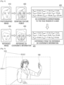
- FIG. 1 is a diagram for illustrating an operation of performing selfie photography, i.e., an operation of taking a selfie or an operation of capturing a selfie, by using an electronic apparatus according to an example embodiment.
- an electronic apparatus 100 may be implemented as a mobile phone such as a smartphone, but the present embodiment is not limited thereto, and the electronic apparatus may be implemented as various types of apparatuses including a camera function and a display function, such as a tablet personal computer (PC), a mobile phone, an e-book, a desktop personal computer (PC), a laptop personal computer (PC), a netbook computer, a personal digital assistant (PDA), a portable multimedia player (PMP), an MP3 player, a mobile medical instrument, a camera, a camcorder, an electronic photo frame or a wearable device (e.g., a head-mounted-device (HMD) smart watch, electronic clothing, an electronic bracelet, an electronic necklace and the like), a near eye display (NED), a large format display (LFD), digital signage, a Digital Information Display (DID) and a video wall.
- the display apparatus 100 has a touch screen embedded therein, and thus the apparatus may be implemented such that a program can be executed by
- the electronic apparatus 100 may provide guide information so that the user may obtain a desirable photograph.
- the term "selfie” may refer to an image that includes oneself (with another person or a part of a group) and is taken by oneself using a camera.
- the electronic apparatus 100 may provide guide information based on a three-dimensional (3D) coordinate corresponding to the face region of a user in a real-time photographed image.
- FIG. 2 is a block diagram for illustrating an electronic apparatus according to an example embodiment.
- the electronic apparatus 100 includes a camera 110, a storage 120, a display 130 and a processor 140.
- the camera 110 may obtain an image by photographing an object according to a user instruction.
- a user instruction may be in various forms such as a touch input, a button input, a voice input and a motion input.
- the object When an object is photographed through the camera 110, the object is converted into an electronic image signal through a semiconductor optical element, such as a charge coupled device (CCD), and the electronic image signal is amplified and converted into a digital signal by an analog signal processor. Then, the digital signal is processed by a digital signal processor, and the processor 140 may control the display 130 to adjust color and brightness of an image that is represented by the digital signal and to display the image with the adjusted color and brightness.
- a semiconductor optical element such as a charge coupled device (CCD)
- the electronic image signal is amplified and converted into a digital signal by an analog signal processor.
- the digital signal is processed by a digital signal processor, and the processor 140 may control the display 130 to adjust color and brightness of an image that is represented by the digital signal and to display the image with the adjusted color and brightness.
- the displayed image may be a still image or a moving image.
- the camera 110 may photograph a still image at a specific time point, or may continuously photograph still images. Also, the camera 110 may provide an image obtained under the control of the processor 140 to the display 130.
- the camera 110 may be implemented in a plural number, such as a front camera provided on the front surface of the electronic apparatus 100 and a rear camera provided on the rear surface of the electronic apparatus 100. For example, selfie photography of which subject is a user may be performed through a front camera.
- the storage 120 may store various types of data, programs or applications for driving/controlling the electronic apparatus 100.
- the storage 120 may store a control program for controlling the electronic apparatus 100 and the processor 140, applications that were initially provided by the manufacturer or downloaded from the outside, databases or relevant data.
- the storage 120 may store at least one of reference 3D coordinate information or reference image information.
- reference 3D coordinate information is information on a 3D coordinate which was obtained from a reference image, and which corresponds to the face region included in the reference image.
- the reference image may be at least one of an image selected by a user or an image provided by the electronic apparatus 100, or it may be a target image aimed by an image photographed by a user.
- the storage 120 may store information on the actual size of the electronic apparatus 100. To be specific, the storage 120 may store information on sizes such as the horizontal length, longitudinal length and thickness of the electronic apparatus 100.
- the storage 120 may be implemented as internal memory such as read-only memory (ROM) and random-access memory (RAM) included in the processor 140, or it may be implemented as separate memory from the processor 140.
- the storage 120 may be implemented in the form of memory embedded in the electronic apparatus 100, or memory that can be attached to or detached from the electronic apparatus 100, depending on the use of the stored data.
- the data may be stored in memory embedded in the electronic apparatus 100, and in the case of data for the extending function of the electronic apparatus 100, the data may be stored in memory that can be attached to or detached from the electronic apparatus 100.
- the memory may be implemented in the form of nonvolatile memory, volatile memory, a hard disc drive (HDD) or a solid state drive (SSD).
- HDD hard disc drive
- SSD solid state drive
- a server may be implemented as a cloud server, but is not limited thereto.
- a server may also be implemented as an external server or an embedded server provided in the electronic apparatus 100, depending on its form of physical implementation.
- the display 130 displays various contents such as a still image, a moving image, texts and music, an application execution screen including various contents, a graphic user interface (GUI) screen and the like.
- contents such as a still image, a moving image, texts and music, an application execution screen including various contents, a graphic user interface (GUI) screen and the like.
- GUI graphic user interface
- the display 130 may display an image (e.g., a preview image or a photographed image) that is being photographed through the camera 110.
- the display 130 may provide a guide GUI for adjusting the photographing position, i.e., the image capture position, of the camera 110 by the control of the processor 140 and a guide GUI (or a guide graphic item) for moving the face region of a user.
- the display 130 may provide a filtering effect such as a sticker to be added to a user image included in a photographed image by the control of the processor 140.
- the display 130 may be implemented in various forms such as a liquid crystal display (LCD), an organic light-emitting diode (OLED), liquid crystal on silicon (LCoS), digital light processing (DLP), a quantum dot (QD) and a micro light-emitting diode (LED) display.
- the display 130 may be implemented in the form of a touch screen that forms an interlayer structure with a touch pad.
- the display 130 may be used as a user interface as described above, as well as an output device.
- a touch screen may be constituted such that it can detect the pressure of a touch input as well as the location and area of a touch input.
- the processor 140 controls the overall operation of the electronic apparatus 100.
- the processor 140 may be implemented as a digital signal processor (DSP) processing digital signals, a microprocessor and a time controller (TCON).
- DSP digital signal processor
- TCON time controller
- the disclosure is not limited thereto, and the processor 140 may include one or more of a central processing unit (CPU), a micro controller unit (MCU), a micro processing unit (MPU), a controller, an application processor (AP) or a communication processor (CP) and an ARM processor, or may be defined by the terms.
- the processor 140 may be implemented as a system on chip (SoC) or a large scale integration (LSI) having a processing algorithm embedded therein, or as a field programmable gate array (FPGA).
- SoC system on chip
- LSI large scale integration
- FPGA field programmable gate array
- the processor 140 may obtain a 3D coordinate corresponding to the face region of a user included in an image photographed through the camera 110.
- the photographed image may be an image in a preview state where the face region of a user can be checked through the display 130.
- the 3D coordinate is a coordinate of which starting point is the camera 110, and it may be implemented as coordinate systems in various forms, such as a rectangular coordinate system, a polar coordinate system and a spherical coordinate system.
- the processor 140 may obtain a 3D coordinate corresponding to the face region of a user by using various methods.
- the processor 140 may obtain a 3D coordinate corresponding to the face region of a user from a photographed two-dimensional (2D) image. For example, the processor 140 may calculate information on the distance among feature points of the face region of a user based on the number of pixels, and thereby obtain a 3D coordinate.
- the processor 140 may obtain a 3D coordinate by receiving position information from an external apparatus (e.g., an accessory attached to a user) provided with a sensor, which is included in a photographed image. For example, the processor 140 may obtain a 3D coordinate based on the distance between the electronic apparatus 100 and an external apparatus, which was calculated based on the position information received from the external apparatus.
- an external apparatus e.g., an accessory attached to a user
- the processor 140 may obtain a 3D coordinate based on the distance between the electronic apparatus 100 and an external apparatus, which was calculated based on the position information received from the external apparatus.
- the processor 140 may obtain a 3D coordinate based on an image received from an external electronic apparatus such as an augmented reality (AR) glass worn by a user.
- the processor 140 may calculate the distance between the electronic apparatus 100 and the face region of a user by comparing information on the size of the electronic apparatus 100 calculated from a received image with information on the actual size of the electronic apparatus 100, and thereby obtain a 3D coordinate.
- AR augmented reality
- the processor 140 may obtain position adjustment information for adjusting the photographing position of the camera 110 based on a difference between the obtained 3D coordinate and the reference 3D coordinate information stored in the storage 120.
- the reference 3D coordinate information is information on a 3D coordinate which was obtained from a reference image, and which corresponds to the face region included in the reference image.
- the reference image may be at least one of an image selected by a user or an image provided by the electronic apparatus 100, or it may be a target image aimed by an image photographed by a user.
- position adjustment information may include the moving distance of the camera 110 by which the camera is to be moved, the moving direction of the camera, the rotating direction of the camera and the degree of rotation of the camera, according to the difference between the obtained 3D coordinate and the reference 3D coordinate information.
- the position adjustment information may be 3D coordinate information corresponding to the difference between the obtained 3D coordinate and the reference 3D coordinate information.
- the processor 140 may control the display 130 to provide a guide GUI for adjusting the photographing position of the camera 110 based on the obtained position adjustment information.
- the photographing position of the camera 110 may include at least one of the photographing distance between the face region of the user and the camera 110, the photographing direction or the photographing angle.
- a guide GUI may be a sign including at least one of the moving distance of the camera 110, the moving direction of the camera 110, the rotating direction of the camera 110 or the degree of rotation of the camera 110.
- a guide GUI may be provided as a sign in the shape of an arrow that indicates directions on the display 130 for displaying the moving direction and the rotating direction.
- a guide GUI may be provided in the form of indicating a clockwise direction or a counterclockwise direction through an arrow shape.
- the processor 140 may display XYZ axes in an area of the display 130, and display a guide GUI on the XYZ axes. Accordingly, the guide GUI may be displayed more stereoscopically.
- the processor 140 may indicate the moving distance and degree of rotation of the camera 110 by adjusting the length of an arrow. That is, the processor 140 may display the length of an arrow to be proportional to the moving distance and degree of rotation of the camera 110. For example, in a case in which the camera 110 needs to be moved to the right side by 20 cm based on the obtained position adjustment information, the processor 140 may display an arrow having a length of 2 cm on the right side of the display 130. Afterwards, when the camera 110 is moved to the right side by 10 cm, the processor 140 may adjust the length of the arrow to 1 cm.
- the processor 140 may obtain information for moving the face region of a user based on a difference between a 3D coordinate corresponding to the face region of a user included in a photographed image and the reference 3D coordinate information stored in the storage 120, and control the display 130 to provide a guide GUI for moving the face region of the user based on the obtained information.
- the information for moving the face region of the user may include information on the moving distance by which the face region of the user is to be moved, the moving direction, the rotating direction and the degree of rotation according to the difference between the obtained 3D coordinate and the reference 3D coordinate information.
- the information for moving the face region of the user may include a distance between the center of the photographed image and the center of the face region.
- the information for moving the face region of the user may be 3D coordinate information corresponding to the difference between the obtained 3D coordinate and the reference 3D coordinate information.
- the processor 140 may provide the display 130 with a guide GUI for guiding movement of the face region of a user, while maintaining the photographing position of the camera 110.
- the processor 140 may provide the display 130 with a guide GUI corresponding to the face of a user in a target position based on the information for moving the face region of the user.
- a guide GUI may be implemented in the form of a circle or an oval, and may guide such that the face region of a user is positioned on the guide GUI.
- the guide GUI may guide such that the face region of a user is positioned on the guide GUI by displaying the face image of the user in a target position.
- the disclosure is not limited thereto, and a guide GUI can obviously be implemented in various forms as long as it performs the role of guiding movement of a user's body.
- the processor 140 may provide a guide for adjusting the photographing position of the camera 110 or moving the face region of a user as voice.
- the processor 140 may provide voice such as "Move the camera to the right side by 10 cm” or “Tilt your face to the left side by 15 degrees” through a speaker, based on the obtained position adjustment information or information for moving the face region of a user.
- the processor 140 may additionally provide a voice guide, as well as providing the display 130 with a guide GUI for adjusting the photographing position of the camera 110 or a guide GUI for moving the face region of a user.
- the processor 140 may identify a plurality of feature points from the face region of a user, calculate information on the distance among the feature points based on the number of pixels, and obtain a 3D coordinate based on the calculated distance information.
- the feature points may be extracted from at least one of the eye, nose or mouth of the user in the photographed image.
- the processor 140 may group the entire pixels in a photographed image into a plurality of blocks consisting of n*m pixels, identify whether there is a feature point in each block, and thereby identify feature points in the face region of the user.
- the processor 140 may calculate distance information such as the size of the eye, the distance between the eyes, the length of the nose and the length of the lip based on the number of pixels. Further, the processor 140 may obtain a 3D coordinate corresponding to the face region of a user by correcting the distance information to be more precise by comparing the calculated distance information with information on average faces stored in the storage 120 or the stored information on the face of the user. For example, the processor 140 may calculate distance information for the size of the eye based on the number of pixels of a photographed image, and obtain information on the size of the eye by comparing the distance information with the stored distance information for an average eye size.
- the processor 140 may calculate information on angles based on comparison of the sizes of the eyes, the angle of the line connecting the eyes, the angle of the nose line and the angle of the lip line.
- the processor 140 may identify facial feature points based on a rectangular 3D coordinate system in which the starting point is assumed as the location of the camera 110.
- the processor 140 may identify the eye, nose and mouth in the face region of a user as feature points, and obtain a rectangular coordinate value of which starting point is the camera 110, based on the number of pixels.
- the processor 140 may obtain position adjustment information for adjusting the photographing position of the camera 110 based on a difference between the obtained 3D coordinate and the reference 3D coordinate information stored in the storage 120.
- the electronic apparatus 100 may calculate the target position of the camera 110 guided by a guide GUI, by using a rotation transformation matrix as follows.
- ⁇ (X axis), ⁇ (Y axis) and ⁇ (Z axis) denote the angle of the camera 110 which is to be changed based on the position adjustment information
- Xcam, Ycam and Zcam denote the distance of the camera 110 by which the camera is to be moved.
- X, Y and Z denote a 3D coordinate corresponding to the position adjustment information
- X', Y' and Z' denote a 3D coordinate corresponding to the target position guided by a guide GUI.
- the electronic apparatus 100 may calculate the target position of the camera 110 based on Formula 1 described above.
- the 3D coordinate obtained in the target position and the reference 3D coordinate information may be identical.
- the processor 140 may provide the display 130 with a guide GUI for adjusting the position of the camera 110 based on the obtained position adjustment information.
- FIG. 5 is a diagram for illustrating the process of obtaining a 3D coordinate based on the position information received from an external apparatus according to another example embodiment.
- the processor 140 may receive the position information of the external apparatus 510 via a communication interface.
- the external apparatus 510 may be present in an image photographed by the electronic apparatus 100.
- the processor 140 may obtain first distance information between the electronic apparatus 100 and the external apparatus 510 based on the received position information.
- the processor 140 may obtain second distance information between the external apparatus 510 included in the photographed image and at least one feature point included in the face region of the user. Further, the processor 140 may obtain a 3D coordinate based on the first distance information and the second distance information
- the external apparatus 510 is an apparatus provided with a sensor that can calculate distance from the electronic apparatus 100.
- the external apparatus 510 may be implemented as accessories such as earrings 510-1 and necklaces or earphones 510-2, and the like.
- the disclosure is not limited thereto, and the external apparatus 510 can be implemented in various forms, if it is an apparatus provided with a sensor that can calculate distance from the electronic apparatus 100, and is attachable to a user.
- position information may include at least one of the distance and the angle between the electronic apparatus 100 and the external apparatus 510.
- the type of the sensor in the external apparatus 510 may include an infrared ray (IR) sensor, an accelerometer, an angular velocity sensor, a gyro sensor, a hall sensor, an ultrasonic sensor and the like.
- IR infrared ray
- An IR sensor is a sensor that emits infrared ray and measures distance according to the amount of the infrared ray reflected on a reflecting object. Based on a value measured by an IR sensor, the distance between the electronic apparatus 100 and the external apparatus 510 can be measured.
- An accelerometer can detect the orientation of gravity. Also, an accelerometer can detect tilt in a motionless state. In addition, an accelerometer can detect the amount of change of the velocity with respect to a time unit.
- An accelerometer may be implemented as a three-axis accelerometer. In case an accelerometer is implemented as a three-axis accelerometer, the accelerometer includes accelerometers of x, y and z axes that are disposed in different directions from one another, and are orthogonal to one another. The accelerometer converts the output values of each of the accelerometers of x, y and z axes into digital values, and provide the values to a preprocessor.
- the preprocessor may include a chopping circuit, an amplifying circuit, a filter, an analog-to-digital (A/D) converter and the like. Accordingly, an electronic signal output from the three-axis accelerometer is chopped, amplified and filtered, and is then converted into a digital voltage value. Then, the angle between the electronic apparatus 100 and the external apparatus 510 can be measured based on the value measured by the accelerometer.
- a gyro sensor is a sensor that detects the amount of change of the preset direction of a user terminal device 200 during a time unit, and thereby detects the angular velocity.
- a gyro sensor a gyroscope having three axes may be used. Through the definite integral value of the angular velocity detected by the gyro sensor, the angle between the electronic apparatus 100 and the external apparatus 510 can be measured.
- a hall sensor is a sensor that measures the magnetic field. Based on the size of the magnetic field measured at the hall sensor, the distance between the electronic apparatus 100 and the external apparatus 510 can be measured.
- the processor 140 may obtain second distance information which is the distance information between the external apparatus 510 and at least one feature point included in the face region of the user based on the number of pixels. Also, the processor 140 may correct the second distance information to be more precise by comparing the calculated second distance information with the information on average bodies stored in the storage 120 or the stored information on the user's body. For example, when the external apparatus 510 is an earphone 510-2 including a sensor, the processor 140 may calculate the distance between the ear to which the earphone 510-2 is attached and the nose based on the number of pixels. Afterwards, the processor 140 may correct the second distance information to be more precise by comparing the distance calculated based on the number of pixels with the distance between the ear and the nose stored in the storage 120.
- the processor 140 may calculate a difference between the calculated distance and the distance stored in the storage 120, and may scale down the calculated down by applying a weight less than 1 to the calculated distance when the difference is greater than a predetermined threshold.
- the weight may have a value greater than 0.5 and less than 1, and the value of the weight may decrease in proportion to the amount of the difference exceeding the predetermined threshold.
- the processor 140 may obtain a 3D coordinate based on the first distance information and the second distance information. Afterwards, the processor 140 may obtain position adjustment information for adjusting the photographing position of the camera 110 based on a difference between the obtained 3D coordinate and the reference 3D coordinate information stored in the storage 120, and provide a guide GUI for adjusting the photographing position of the camera 110 based on the obtained position adjustment information.
- the distance information between the electronic apparatus 100 and the external apparatus 510 is relatively correct. Accordingly, a precise 3D coordinate corresponding to the face region of the user can be obtained.
- FIG. 6 is a diagram for illustrating the process of obtaining a 3D coordinate based on an image received from an external electronic apparatus according to the invention.
- the processor 140 may receive, from the external electronic apparatus 610, an image 620 including the electronic apparatus 100 through the communication interface.
- the processor 140 may compare the size of the electronic apparatus 100 obtained from the received image 620 with the actual size of the electronic apparatus 100 stored in the storage 120, and thereby obtain a 3D coordinate.
- the external electronic apparatus 610 may be implemented as augmented reality (AR) glass including the camera 110.
- the size may be information including the horizontal length, longitudinal length and thickness of the electronic apparatus 100.
- the processor 140 may calculate the distance between the electronic apparatus 100 and the face region of the user by comparing the size of the electronic apparatus 100 calculated from the image 620 received from the external electronic apparatus 610 with the actual size of the electronic apparatus 100. Also, the processor 140 may calculate the size of the electronic apparatus 100 from the received image 620 based on the number of pixels.
- the storage 120 stores a length of 15 cm and a width of 6 cm as the actual dimension of the electronic apparatus 100.
- length may be also referred to as “longitudinal length” or “horizontal length”
- width may be also referred to as “vertical length”.
- the processor 140 may calculate the number of pixels in the horizontal length and in the longitudinal length of the electronic apparatus 100. Further, the processor 140 may calculate the relation between the number of pixels and the actual size, and calculate the distance between the electronic apparatus 100 and the face region of the user based on the calculated information.
- the processor 140 may obtain a 3D coordinate based on the calculated distance between the electronic apparatus 100 and the face region of the user. Afterwards, the processor 140 may obtain position adjustment information for adjusting the photographing position of the camera 110 based on the difference between the obtained 3D coordinate and the reference 3D coordinate information stored in the storage 120, and provide a guide GUI for adjusting the photographing position of the camera 110 based on the obtained position adjustment information.
- the distance between the electronic apparatus 100 and the face region of the user can be calculated relatively precisely by comparing the size of the electronic apparatus 100 calculated from the image 620 received from the external electronic apparatus 610 with the actual size of the electronic apparatus 100.
- the processor 140 can obtain a precise 3D coordinate corresponding to the face region of the user.
- the external electronic apparatus 610 may be implemented in various forms other than AR glass, if it is an apparatus that can photograph the electronic apparatus 100 and transmit the photographed image to the electronic apparatus 100.
- the processor 140 may perform photographing automatically. Also, the processor 140 may obtain position adjustment information based on a difference between a 3D coordinate corresponding to the face region of the user included in a photographed image and reference 3D coordinate information in real time. Further, the processor 140 may perform photographing an image automatically, based on identifying that the 3D coordinate and the reference 3D coordinate information are identical based on the position adjustment information that is measured in real time (i.e., if the photographing position is adjusted to a target position or the face region of the user is moved to a target position).
- the processor 140 may provide a feedback informing that the photographing position of the camera 110 or the face region of the user is adjusted to a target position, or perform photographing automatically after a preset time has lapsed after providing a feedback.
- a feedback may be in the form of, for example, vibrating the electronic apparatus 100, or outputting specific sound or voice.
- a feedback may be in the form of an LED light source emitting light.
- the processor 140 may control the display 130 to adjust at least one of the size, direction or form of a sticker to be added to a user image included in a photographed image based on a 3D coordinate corresponding to the face region of the user included in the photographed image, and display the image.
- a 3D coordinate corresponding to the face region of a user were described earlier, detailed description therefor will be omitted.
- a sticker may be all objects added to a user image to decorate the user image included in a photographed image.
- a sticker may be implemented in a form wherein a shape in the form of a rabbit's ears is added to the face region of a user image, or in a form wherein a cosmetic effect is applied to a user image.
- the disclosure is not limited thereto, and a sticker can obviously be implemented in various forms if it is an object that can decorate a user image.
- the processor 140 may adjust at least one of the size, direction or form of a sticker to be added to a user image based on the obtained 3D coordinate.
- a sticker in the shape of rabbit ears may be added to the head portion of the face region of a user.
- the processor 140 may add a sticker based on the state of the user image based on a 3D coordinate. For example, if a user looks at the left, the processor 140 may express a cubic effect by adjusting the sizes of the rabbit's left and right ears to match the user's line of sight. Afterwards, if the looks at the right, the processor 140 may readjust the sizes of the rabbit's left and right ears.
- a sticker is applied based on a 3D coordinate. Accordingly, a sticker can be applied to a user image while being adjusted relatively precisely.
- the AR glass may obtain position adjustment information for adjusting the photographing position of a smart phone based on a difference between a 3D coordinate corresponding to the face region of a user included in a photographed image and the stored reference 3D coordinate information. Then, based on the obtained position adjustment information, the AR glass may provide a guide GUI for adjusting the position of the smartphone on the glass as an AR object. That is, the AR glass may provide the target position of the smartphone based on the position adjustment information on the glass, and guide the position.
- an AR object is a virtual object related to the actual object included in an image, and in the disclosure, an AR object may be used to represent a guide GUI for adjusting the position of a smart phone.
- an AR object may be provided to an image photographed by a camera.
- an AR object may be provided in various forms, such as being displayed while being rendered on a photographed image, being displayed in the form of an on-screen display (OSD) on a photographed image, or being displayed on a layer that is different from the layer wherein a photographed image is displayed.
- OSD on-screen display
- an AR object may be provided based on the position of an object that is shown to a user through glass implemented as a transparent display.
- an AR object may be provided on glass based on a method such as digital light processing (DLP) and a laser scanning projector (LSP).
- DLP digital light processing
- LSP laser scanning projector
- FIG. 3 is a block diagram for illustrating the electronic apparatus of FIG. 2 in greater detail.
- the electronic apparatus 100 includes a camera 110, a storage 120, a display 130, a processor 140, a communication interface 150 and a speaker 160.
- a camera 110 the electronic apparatus 100 includes a camera 110, a storage 120, a display 130, a processor 140, a communication interface 150 and a speaker 160.
- a communication interface 150 the electronic apparatus 100 includes a speaker 160.
- the processor 140 may include a CPU 141, a ROM (or nonvolatile memory) storing a control program for controlling the electronic apparatus 100 and a RAM (or volatile memory) which stores data that is input from the outside of the electronic apparatus 100 or is used as a storing area corresponding to the various kinds of work performed at the electronic apparatus 100.
- the processor 140 may execute the operating system (OS), programs and various applications stored in the storage 120. Also, the processor 140 may include a single core, a dual core, a triple core, a quad core and a core of multiple numbers thereof.
- OS operating system
- the processor 140 may include a single core, a dual core, a triple core, a quad core and a core of multiple numbers thereof.
- the CPU 141 accesses the storage 120, and performs booting by using the O/S stored in the storage 120. Also, the CPU performs diverse operations by using various kinds of programs, contents, data and the like stored in the storage 120.
- the communication interface 150 performs communication with an external apparatus (e.g., an accessory including a sensor) or an external electronic apparatus (e.g., AR glass).
- the communication interface 150 may perform wireless communication with the user terminal device 200 by a communication method such as Bluetooth (BT), wireless fidelity (Wi-Fi), zigbee and infrared (IR).
- the processor 140 may perform communication with an external apparatus or an external electronic apparatus through various communication methods such as a serial interface, a universal serial bus (USB) and near field communication (NFC).
- the communication interface 150 may become an interlocked state by performing communication according to a predefined communication method with an external apparatus or an external electronic apparatus.
- interlocking may mean all states wherein communication is possible, such as an operation of initializing communication between the electronic apparatus 100 and an external apparatus or an external electronic apparatus, an operation of forming a network and an operation of performing paring of apparatuses.
- apparatus identification information of an external apparatus or an external electronic apparatus may be provided to the electronic apparatus 100, and a process of paring between the two apparatuses may be performed accordingly.
- nearby apparatuses may be searched through a digital living network alliance (DLNA) technology, and paring with the searched apparatuses may be performed, and as a result, the communication interface 150 may become an interlocked state.
- DLNA digital living network alliance
- position information may be received from an external apparatus through the communication interface 150, and an image including the electronic apparatus 100 may be received from an external electronic apparatus.
- the speaker 160 is a component for outputting various kinds of sound.
- the speaker 160 may output a voice guide for adjusting the photographing position of the camera 110 or a voice guide for moving the face region of a user according to the control by the processor 140. Further, when the photographing position of the camera 110 or the face region of a user is adjusted to a target position, the speaker 160 may output a voice feedback informing this according to the control by the processor 140.
- the microphone 170 is a component for receiving voice uttered by a user.
- the microphone 170 may receive voice related to photographing, and transmit the voice to the processor 140.
- FIG. 4 is a diagram for illustrating the process of obtaining position adjustment information according to an example embodiment.
- the electronic apparatus 100 may obtain a 3D coordinate corresponding to the face region of a user included in an image 410 that is photographed through the camera 1100.
- the electronic apparatus 100 may identify a plurality of feature points 420 in the face region of a user.
- the features points may be feature points included in at least one of the eye, nose or mouth of a user.
- technologies such as face detection and face recognition may be used.
- the electronic apparatus 100 may calculate information on the distance among the feature points based on the number of pixels, and obtain a 3D coordinate based on the calculated distance information.
- the electronic apparatus 100 may calculate distance information such as the size of the eye, the distance between the eyes, the length of the nose and the length of the lip based on the number of pixels. Further, the electronic apparatus 100 may obtain a 3D coordinate corresponding to the face region of a user by correcting the distance information to be more precise by comparing the calculated distance information with the stored information on average faces or the stored information on the face of the user. For example, the electronic apparatus 100 may calculate the distance between the face of the user and the camera 110 based on the information on the distance between the eyes calculated from a photographed image.
- the electronic apparatus 100 may calculate information on angles of facial features based on comparison of the sizes of the eyes, the angle of the line connecting the eyes, the angle of the nose line and the angle of the lip line.
- a 3D coordinate is represented by a rectangular coordinate system in which a starting point is the camera 110.
- the electronic apparatus 100 may identify the eye, nose and mouth in the face region of a user as feature points, and obtain a rectangular coordinate value of which starting point is the camera 110, based on the number of pixels.
- the electronic apparatus 100 may obtain, from a reference image 440, a 3D coordinate corresponding to the face region of the user included in a photographed image, and may compare the 3D coordinate with reference 3D coordinate information 450.
- the electronic apparatus 100 may store the reference image 440, or store only the reference 3D coordinate information 450.
- the electronic apparatus 100 may obtain position adjustment information for adjusting the photographing position of the camera 110 by calculating a difference between a 3D coordinate corresponding to the face region of the user included in a photographed image and the reference 3D coordinate information 460.
- the 3D coordinate obtained in the target position and the reference 3D coordinate information may be identical.
- the electronic apparatus 100 may provide the display 130 with a guide GUI for adjusting the position of the camera 110 based on the obtained position adjustment information.
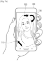
- FIGS. 7A-7D are diagrams for illustrating the types of guide GUIs according to an example embodiment.
- the electronic apparatus 100 may provide guide GUIs 710, 720, and 730 based on the position adjustment information for adjusting the photographing position of the camera 110.
- the position adjustment information may include information on the moving distance of the camera 110 by which the camera 110 is to be moved, the moving direction of the camera 110, the rotating direction of the camera 110 and the degree of rotation of the camera 110, according to the difference between the obtained 3D coordinate and the reference 3D coordinate information. Further, the position adjustment information may be 3D coordinate information corresponding to the difference between the obtained 3D coordinate and the reference 3D coordinate information.
- the guide GUIs 710, 720, and 730 may indicate at least one of the moving distance of the camera 110, the moving direction of the camera 110, the rotating direction of the camera 110 or the degree of rotation of the camera 110.
- the guide GUIs 710, 720, and/or 730 may have the shape of an arrow that indicates directions for displaying the moving direction and the rotating direction.
- the guide GUIs 710, 720, and/or 730 may be provided as signs in the shape of an arrow that indicates a clockwise direction or a counterclockwise direction for displaying the rotating direction.
- the electronic apparatus 100 may provide a guide GUI that includes a first graphic item 710, a second graphic item 720, and a third graphic item 730.
- the first graphic item 710 may guide the user to move the lower end of the electronic apparatus 100 to the upper left side
- the second graphic item 720 may guide the user to move the electronic apparatus 100 to the right side
- the third graphic item 730 may guide the user to rotate the electronic apparatus 100 in the direction of an arrow.
- the guide GUI is described as including the three graphic items 710, 720, and 730, but each of the graphic items 710, 720, and 730 may be referred to as a guide GUI.
- the third graphic item 730 may be referred to as a rotation guide GUI.
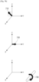
- the electronic apparatus 100 may display the first graphic item 710, the second graphic item 720, and the third graphic item 730 on XYZ axes, respectively.
- the electronic apparatus 100 may display a dotted line on the XZ axes and display an arrow, and thereby provide the first graphic item 710 that guides movement of the electronic apparatus 100 to the upper left side.
- the electronic apparatus 100 may display an arrow guiding movement on an X axis, and thereby provide the second graphic item 720 that guides the electronic apparatus 100 to the right side.
- the electronic apparatus 100 may display an arrow in a clockwise direction that guides rotational movement, and thereby provide the third graphic item 730.
- the electronic apparatus 100 may display a separate rotating axis, and thereby display rotating directions clearly.
- the electronic apparatus 100 may display a rotating axis corresponding to the Y axis, and use an arrow in a clockwise direction, and thereby provide the third graphic item 730.
- the electronic apparatus 100 may provide the third graphic item 730 on the XYZ axes without a separate rotating axis.
- the electronic apparatus 100 may display an angle by which the electronic apparatus 100 is to be rotated in the direction indicated by the third graphic item 730.
- the electronic apparatus 100 may obtain information for moving the face region of a user based on a difference between a 3D coordinate corresponding to the face region of the user included in a photographed image and the stored reference 3D coordinate information, and provide a guide GUI 740 for moving the face region of the user based on the obtained information.
- the information for moving the face region of the user may include information on the moving distance by which the face region of the user is to be moved, the moving direction, the rotating direction and the degree of rotation, according to the difference between the obtained 3D coordinate and the reference 3D coordinate information.
- the information for moving the face region of the user may be 3D coordinate information corresponding to the difference between the obtained 3D coordinate and the reference 3D coordinate information.
- the electronic apparatus 100 may provide the display 130 with the guide GUI 740 that guides movement of the face region of a user while maintaining the photographing position of the camera 110.
- the guide GUI 740 that corresponds to the face of a user may be in the form wherein the face region of the user photographed is virtually moved and displayed.
- the electronic apparatus 100 may provide a guide GUI in the form wherein the face region of a user photographed is displayed in a target position with dotted lines.
- the guide GUI 740 that corresponds to the face of a user may be displayed in the form of a circle or an oval.
- the disclosure is not limited thereto, and the guide GUI 740 can be implemented in various forms if it is a component that performs the role of guiding movement of a user's body.
- FIG. 7D is a diagram for illustrating guide GUIs in case the electronic apparatus 100 is implemented as AR glass.
- the AR glass may obtain position adjustment information for adjusting the photographing position of a smart phone based on a difference between a 3D coordinate corresponding to the face region of a user included in a photographed image and the stored reference 3D coordinate information. Further, the AR glass may provide a guide GUI 750 for adjusting the position of the smart phone based on the obtained position adjustment information to the glass (display).
- the AR glass may provide the target position of a smart phone based on position adjustment information to the glass, and thereby guide the position.
- the AR glass may provide a guide GUI 760 in the shape of an arrow and thereby guide the direction and the distance by which the smart phone is to be moved.
- FIG. 8 is a diagram for illustrating a guide GUI which is in proportion to the degree of movement of a camera according to an example embodiment.
- FIG. 8 is a diagram wherein an arrow is provided as a guide GUI, and the electronic apparatus 100 may display the moving distance of the camera 110 by adjusting the length of the arrow. That is, the electronic apparatus 100 may display the length of the arrow to be in proportion to the moving distance of the camera 110. For example, when the electronic apparatus 100 determines that the camera 110 needs to be moved to the right side by 20 cm based on the obtained position adjustment information, the electronic apparatus 100 may display a rightwards arrow having the length of 2 cm on the display 130. Afterwards, when the camera 110 is moved to the right side by 10 cm, the electronic apparatus 100 may adjust the length of the rightwards arrow to 1 cm.
- the length of the rightwards arrow may gradually decrease as the camera 110 moves closer to a target position, and may gradually increase as the camera 110 moves away from the target position.
- the electronic apparatus 100 may display a leftwards arrow instead of the rightwards arrow.
- the electronic apparatus 100 may adjust the length of the arrow to display the degree of rotation of the camera 110 as well as the moving distance.
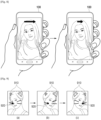
- FIG. 9 is a diagram for illustrating adjustment of a sticker that is added to a user image, according to an example embodiment.
- a sticker may be all objects added to a user image to decorate the user image included in a photographed image.
- a sticker may be implemented in a form wherein a shape in the form of a rabbit's ears 910 is added to the face region of a user.
- the electronic apparatus 100 may adjust at least one of the size, direction or form of a sticker to be added to a user image based on a 3D coordinate corresponding to the face region of the user included in a photographed image.
- a 3D coordinate corresponding to the face region of the user included in a photographed image.
- the electronic apparatus 100 may obtain a 3D coordinate corresponding thereto. Then, based on the obtained 3D coordinate, the electronic apparatus 100 may adjust the sizes of the rabbit ears 910 on the left and right sides. As an example, the electronic apparatus 100 may express a cubic effect 920 by adjusting the size of the rabbit ear 910 on the right side to be bigger than the size of the rabbit ear 910 on the left side.
- the user may not be able to obtain a precise 3D coordinate according to his or her movement, even though the user's posture has been changed, and therefore in related art, the size and direction of the sticker may not be adjusted to correspond to the changed posture, as illustrated in image (b) of FIG. 9 .
- a 3D coordinate corresponding to the face region of a user included in a photographed image can be obtained in real time.
- the electronic apparatus 100 may adjust the size and direction of the sticker to correspond to the user image.
- the electronic apparatus 100 may express a cubic effect 920 by adjusting the size of the rabbit ear 910 on the left side to be bigger than the size of the rabbit ear 910 on the right side.
- a sticker is applied based on a 3D coordinate.
- a sticker can be applied to a user image while being adjusted relatively precisely.
- FIG. 9 illustrates an embodiment wherein a shape in the form of a rabbit's ears 910 is added to the face region of a user image.
- various stickers may be applied based on a 3D coordinate, for example, a form wherein a cosmetic effect is applied to a user image.
- FIG. 10 is a sequence diagram for illustrating an operation of guiding the movement of a camera by comparing 3D coordinates according to an example embodiment.
- the electronic apparatus 100 may store a reference image in operation S1010.
- the reference image may be at least one of an image selected by a user or an image provided by the electronic apparatus 100, or it may be a target image aimed by an image photographed by a user.
- the electronic apparatus 100 may obtain a 3D coordinate from a reference image, and store the information on the 3D coordinate in operation S1020.
- reference 3D coordinate information is information on a 3D coordinate corresponding to the face region included in the reference image.
- the electronic apparatus 100 may not store a reference image separately, but store only the reference 3D coordinate information obtained from the reference image.
- the electronic apparatus 100 may photograph an image including the face region of a user in operation S1030. Further, the electronic apparatus 100 may obtain a 3D coordinate corresponding to the face region of the user from the photographed image in operation S1040.
- the photographed image may be an image in a preview state where the face region of a user can be checked.
- the electronic apparatus 100 may identify a difference between two 3D coordinates in operation S1050.
- the electronic apparatus 100 may obtain position adjustment information for adjusting the photographing position of the camera 110 based on a difference between a 3D coordinate corresponding to the face region of the user included in a photographed image and the stored reference 3D coordinate information, in operation S1060.
- position adjustment information may include information on the moving distance of the camera 110 by which the camera 110 is to be moved, the moving direction of the camera 110, the rotating direction of the camera 110 and the degree of rotation of the camera 110, according to the difference between the obtained 3D coordinate and the reference 3D coordinate information. Further, the position adjustment information may be 3D coordinate information corresponding to the difference between the obtained 3D coordinate and the reference 3D coordinate information.
- the electronic apparatus 100 may provide a guide GUI for adjusting the photographing position of the camera 110 based on the obtained position adjustment information in operation S1070.
- the electronic apparatus 100 may determine a movement direction of the electronic apparatus 100 in which the obtained 3D coordinate and the reference 3D coordinate information decreases, and may generate the guide GUI to indicate the movement direction.
- the guide GUI may be a sign including at least one of the moving distance of the camera 110, the moving direction of the camera 110, the rotating direction of the camera 110 or the degree of rotation of the camera 110.
- the guide GUI may be provided as a sign in the shape of an arrow that indicates directions for displaying the moving direction and the rotating direction.
- the guide GUI may be provided as a sign in the shape of an arrow that indicates a clockwise direction or a counterclockwise direction for displaying the rotating direction.
- the guide GUI may also be displayed on XYZ axes.
- the photographing position of the camera 110 may be adjusted based on a user's manipulation in operation S1080. As the photographing position of the camera 110 is changed as described above, a photographed image in a preview state may be changed.
- the electronic apparatus 100 may perform photographing automatically.
- FIG. 11 is a flow chart for illustrating a method of controlling an electronic apparatus according to an example embodiment.
- the electronic apparatus 100 may obtain a 3D coordinate corresponding to the face region of a user included in an image photographed through the camera 110, in operation S1110.
- the electronic apparatus 100 may identify a plurality of feature points from the face region of a user, calculate information on the distance among the feature points based on the number of pixels, and obtain a 3D coordinate based on the calculated distance information.
- the feature points may be at least one of the eye, nose or mouth of the user.
- the electronic apparatus 100 may, based on receiving from an external apparatus included in a photographed image the position information of the external apparatus, obtain first distance information between the electronic apparatus and the external apparatus based on the received position information, obtain second distance information between the external apparatus included in the photographed image and at least one feature point included in the face region of the user, and obtain a 3D coordinate based on the first distance information and the second distance information.
- the external apparatus may be an apparatus provided with a sensor that can calculate distance from the electronic apparatus 100.
- position information may be information including at least one of the distance between the electronic apparatus 100 and the external apparatus or the angle.
- a sensor may be implemented as an IR sensor, an accelerometer, an angular velocity sensor, a gyro sensor, a hall sensor, an ultrasonic sensor and the like.
- the electronic apparatus 100 may, based on receiving from an external electronic apparatus an image including the electronic apparatus 100, compare the size of the electronic apparatus 100 obtained from the received image with the actual size of the pre-stored electronic apparatus 100, and thereby obtain a 3D coordinate.
- the external electronic apparatus may be implemented as AR glass including a camera.
- the sizes may be information including the horizontal length, longitudinal length and thickness of the electronic apparatus 100.
- the electronic apparatus 100 may calculate the distance between the electronic apparatus 100 and the face region of the user by comparing the size of the electronic apparatus 100 calculated from an image received from an external electronic apparatus with the actual size of the electronic apparatus 100. Also, the electronic apparatus 100 may calculate the size of the electronic apparatus 100 from the received image based on the number of pixels.
- the electronic apparatus 100 may obtain position adjustment information for adjusting the photographing position of the camera 110 based on a difference between the obtained 3D coordinate and reference 3D coordinate information in operation S1120.
- the photographing position of the camera 110 may include at least one of the photographing distance between the face region of the user and the camera 110, the photographing direction or the photographing angle.
- the electronic apparatus 100 may provide a guide GUI for adjusting the photographing position of the camera 110 based on the obtained position adjustment information in operation S1130.
- the guide GUI may include at least one of the moving distance of the camera 110, the moving direction of the camera 110, the rotating direction of the camera 110 or the degree of rotation of the camera 110.
- the electronic apparatus 100 may obtain information for moving the face region of a user based on a difference between a 3D coordinate corresponding to the face region of a user included in a photographed image and reference 3D coordinate information, and provide a guide GUI for moving the face region of the user based on the obtained information.
- the electronic apparatus 100 may provide a guide for adjusting the photographing position of the camera 110 or moving the face region of a user as voice.
- the electronic apparatus 100 may provide voice such as "Move the camera to the right side by 10 cm” or "Tilt your face to the left side by 15 degrees” through a speaker, based on the obtained position adjustment information or information for moving the face region of a user.
- At least some of the components used in the methods according to the various embodiments of the disclosure described above may be installed on conventional electronic apparatuses, or may be implemented in the form of an application which is software that a user will directly use in an operating system (OS).
- An application may be provided in the form of an icon interface on the screen of the electronic apparatus 100.
- At least some of the components in the various embodiments of the disclosure described above may be implemented through an embedded server provided to an electronic apparatus, or through an external server of an electronic apparatus.
- the various embodiments of the disclosure described above may be implemented in a recording medium that is readable by a computer or a device similar thereto, by using software, hardware or a combination thereof.
- the embodiments described in this specification may be implemented as a processor itself.
- the embodiments such as procedures and functions described in this specification may be implemented as separate software modules. Each of the software modules may perform one or more functions and operations described in this specification.
- an exemplary embodiment can be embodied as computer-readable code on a computer-readable recording medium.
- the computer-readable recording medium is any data storage device that can store data that can be thereafter read by a computer system. Examples of the computer-readable recording medium include read-only memory (ROM), random-access memory (RAM), CD-ROMs, magnetic tapes, floppy disks, and optical data storage devices.
- the computer-readable recording medium can also be distributed over network-coupled computer systems so that the computer-readable code is stored and executed in a distributed fashion.
- an exemplary embodiment may be written as a computer program transmitted over a computer-readable transmission medium, such as a carrier wave, and received and implemented in general-use or special-purpose digital computers that execute the programs.
- one or more units of the above-described apparatuses and devices can include circuitry, a processor, a microprocessor, etc., and may execute a computer program stored in a computer-readable medium.
- a non-transitory computer-readable medium may store computer instructions that make the electronic apparatus perform an operation of obtaining a 3D coordinate corresponding to the face region of a user included in an image photographed by a camera, an operation of obtaining position adjustment information for adjusting the photographing position of the camera based on a difference between the obtained 3D coordinate and reference 3D coordinate information, and an operation of providing a guide GUI for adjusting the photographing position of the camera based on the obtained position adjustment information.
Landscapes
- Engineering & Computer Science (AREA)
- Theoretical Computer Science (AREA)
- Physics & Mathematics (AREA)
- General Physics & Mathematics (AREA)
- Human Computer Interaction (AREA)
- Multimedia (AREA)
- Signal Processing (AREA)
- General Engineering & Computer Science (AREA)
- Computer Vision & Pattern Recognition (AREA)
- Software Systems (AREA)
- Computer Networks & Wireless Communication (AREA)
- Oral & Maxillofacial Surgery (AREA)
- Health & Medical Sciences (AREA)
- General Health & Medical Sciences (AREA)
- User Interface Of Digital Computer (AREA)
- Studio Devices (AREA)
- Processing Or Creating Images (AREA)
Claims (11)
- Lunettes de réalité augmentée, AR, les lunettes AR comprenant :un écran ;une interface de communication pour communiquer avec un appareil électronique;un stockage ; etun processeur configuré pour exécuter des instructions stockées dans le stockage au moins pour :obtenir une image, à partir de l'appareil électronique via l'interface de communication, incluant les lunettes AR portées par un utilisateur, où l'image est obtenue par une caméra de l'appareil électronique ;caractérisé en ce que le processeur est configuré pour :obtenir une coordonnée tridimensionnelle, 3D, d'une région du visage de l'utilisateur sur la base de l'image obtenue ;obtenir des informations d'ajustement de position pour ajuster une position de photographie de l'appareil électronique sur la base d'une différence entre la coordonnée 3D de la région du visage et une coordonnée 3D de référence stockée dans le stockage ; etcommander à l'écran d'afficher une interface utilisateur graphique, GUI, de guide pour ajuster la position de photographie de l'appareil électronique sur la base des informations d'ajustement de position,où la GUI de guide est représentée par un objet virtuel et inclut au moins un parmi une direction de rotation de l'appareil électronique et un degré de rotation de l'appareil électronique, etoù la GUI de guide inclut un signe en forme de flèche qui indique une direction dans le sens des aiguilles d'une montre ou une direction dans le sens inverse des aiguilles d'une montre pour afficher la direction de rotation.
- Lunettes AR selon la revendication 1, où le processeur est en outre configuré pour :
obtenir la coordonnée 3D de référence à partir d'une image de référence :déterminer une différence de taille entre une taille d'au moins un organe situé dans la région du visage dans l'image obtenue de l'utilisateur, où l'au moins un organe est au moins un parmi un œil, un nez ou une bouche de l'utilisateur, et une taille d'un organe correspondant dans l'image de référence ; etobtenir les informations d'ajustement de position sur la base de la différence de taille entre l'au moins un organe situé dans la région du visage dans l'image obtenue de l'utilisateur et la taille de l'organe correspondant dans l'image de référence. - Lunettes AR selon la revendication 1,
où la position de photographie de l'appareil électronique inclut au moins un parmi une distance de photographie entre la région du visage de l'utilisateur et l'appareil électronique, une direction de photographie et un angle de photographie. - Lunettes AR selon la revendication 1,
où le processeur est en outre configuré pour identifier une pluralité de points caractéristiques de la région du visage de l'utilisateur, calculer des informations sur une distance entre la pluralité de points caractéristiques sur la base d'un nombre de pixels dans la distance, et obtenir la coordonnée 3D de la région du visage sur la base des informations sur la distance. - Lunettes AR selon la revendication 1, comprenant en outre : un capteur qui peut mesurer une distance et un angle entre l'appareil électronique et les lunettes AR,
où le processeur est en outre configuré pour :obtenir des informations de position de l'appareil électronique, où les informations de position incluent la distance et l'angle entre les lunettes AR et l'appareil électronique ;obtenir des premières informations de distance entre les lunettes AR et l'appareil électronique sur la base des informations de position de l'appareil électronique ;obtenir des deuxièmes informations de distance entre les lunettes AR incluses dans l'image et au moins un point caractéristique inclus dans la région du visage de l'utilisateur ; etobtenir la coordonnée 3D de la région du visage sur la base des premières informations de distance et des deuxièmes informations de distance. - Lunettes AR selon la revendication 1,
où le processeur est configuré pour obtenir une image de l'appareil électronique par la caméra, et obtenir la coordonnée 3D de la région du visage sur la base d'une comparaison entre une taille de l'appareil électronique obtenue à partir de l'image de l'appareil électronique et une taille réelle de l'appareil électronique stockée dans la mémoire. - Lunettes AR selon la revendication 1,
où le processeur est en outre configuré pour commander à l'écran d'ajuster au moins une parmi une taille, une direction et une forme d'un autocollant à ajouter à l'image de l'utilisateur sur la coordonnée 3D de la région du visage, et afficher l'image de l'utilisateur avec l'autocollant. - Procédé de commande de lunettes de réalité augmentée, AR, et de stockage d'une coordonnée tridimensionnelle, 3D, de référence, le procédé de commande des lunettes AR comprenant :obtenir une image, à partir d'un appareil électronique, incluant les lunettes AR portées par un utilisateur, où l'image est obtenue par une caméra de l'appareil électronique;caractérisé par :obtenir une coordonnée 3D correspondant à une région du visage de l'utilisateur sur la base de l'image obtenue ;obtenir des information d'ajustement de position pour ajuster une position de photographie de l'appareil électronique sur la base d'une différence entre la coordonnée 3D de la région du visage et la coordonnée 3D de référence ; etafficher une interface utilisateur graphique, GUI, de guide pour ajuster la position de photographie de l'appareil électronique sur la base des informations d'ajustement de position,où la GUI de guide est représentée par un objet virtuel et inclut au moins un parmi une direction de rotation de l'appareil électronique et un degré de rotation de l'appareil électronique, etoù la GUI de guide inclut un signe en forme de flèche qui indique une direction dans le sens des aiguilles d'une montre ou une direction dans le sens inverse des aiguilles d'une montre pour afficher la direction de rotation.
- Procédé de commande des lunettes AR selon la revendication 8, comprenant en outreobtenir des informations pour déplacer la région du visage de l'utilisateur sur la base de la différence entre la coordonnée 3D de la région du visage et la coordonnée 3D de référence ; etfournir la GUI de guide pour déplacer la région du visage de l'utilisateur sur la base des informations pour déplacer la région du visage de l'utilisateur.
- Procédé de commande des lunettes AR selon la revendication 8,
où la position de photographie de l'appareil électronique inclut au moins un parmi une distance de photographie entre la région du visage de l'utilisateur et l'appareil électronique, une direction de photographie et un angle de photographie. - Procédé de commande des lunettes AR selon la revendication 8,
où l'obtention de la coordonnée 3D comprend :
identifier une pluralité de points caractéristiques de la région du visage de l'utilisateur, calculer des informations sur une distance entre la pluralité de points caractéristiques sur la base d'un nombre de pixels dans la distance, et obtenir la coordonnée 3D de la région du visage sur la base des informations sur la distance.
Applications Claiming Priority (2)
| Application Number | Priority Date | Filing Date | Title |
|---|---|---|---|
| KR1020180095881A KR102537784B1 (ko) | 2018-08-17 | 2018-08-17 | 전자 장치 및 그 제어 방법 |
| PCT/KR2019/009506 WO2020036343A1 (fr) | 2018-08-17 | 2019-07-31 | Dispositif électronique et procédé de commande correspondant |
Publications (4)
| Publication Number | Publication Date |
|---|---|
| EP3785103A1 EP3785103A1 (fr) | 2021-03-03 |
| EP3785103A4 EP3785103A4 (fr) | 2021-06-09 |
| EP3785103B1 true EP3785103B1 (fr) | 2025-03-19 |
| EP3785103C0 EP3785103C0 (fr) | 2025-03-19 |
Family
ID=69523606
Family Applications (1)
| Application Number | Title | Priority Date | Filing Date |
|---|---|---|---|
| EP19849994.9A Active EP3785103B1 (fr) | 2018-08-17 | 2019-07-31 | Dispositif électronique et procédé de commande correspondant |
Country Status (5)
| Country | Link |
|---|---|
| US (1) | US10986265B2 (fr) |
| EP (1) | EP3785103B1 (fr) |
| KR (1) | KR102537784B1 (fr) |
| CN (1) | CN112334869B (fr) |
| WO (1) | WO2020036343A1 (fr) |
Families Citing this family (18)
| Publication number | Priority date | Publication date | Assignee | Title |
|---|---|---|---|---|
| CN107679446B (zh) * | 2017-08-17 | 2019-03-15 | 平安科技(深圳)有限公司 | 人脸姿态检测方法、装置及存储介质 |
| JP6881188B2 (ja) * | 2017-09-27 | 2021-06-02 | オムロン株式会社 | 位置検出装置およびプログラム |
| JP7378934B2 (ja) * | 2019-01-29 | 2023-11-14 | キヤノン株式会社 | 情報処理装置、情報処理方法及びシステム |
| US11308618B2 (en) | 2019-04-14 | 2022-04-19 | Holovisions LLC | Healthy-Selfie(TM): a portable phone-moving device for telemedicine imaging using a mobile phone |
| US12014500B2 (en) | 2019-04-14 | 2024-06-18 | Holovisions LLC | Healthy-Selfie(TM): methods for remote medical imaging using a conventional smart phone or augmented reality eyewear |
| CN110428390B (zh) * | 2019-07-18 | 2022-08-26 | 北京达佳互联信息技术有限公司 | 一种素材展示方法、装置、电子设备和存储介质 |
| US11595632B2 (en) * | 2019-12-20 | 2023-02-28 | Samsara Networks Inc. | Camera configuration system |
| CN113542575A (zh) * | 2020-04-15 | 2021-10-22 | 荣耀终端有限公司 | 设备位姿调整方法和图像拍摄方法及电子设备 |
| CN121501235A (zh) * | 2020-05-13 | 2026-02-10 | 华为技术有限公司 | 图像显示方法、装置、终端设备、存储介质及程序产品 |
| CN111914693A (zh) * | 2020-07-16 | 2020-11-10 | 上海云从企业发展有限公司 | 一种人脸姿态调整方法、系统、装置、设备及介质 |
| KR20220074317A (ko) * | 2020-11-27 | 2022-06-03 | 변주영 | 전자장치 및 라이다 센서를 이용한 전자장치 제어 방법 |
| WO2022146729A1 (fr) | 2020-12-29 | 2022-07-07 | Snap Inc. | Interface utilisateur corporelle pour composants de réalité augmentée |
| US11500454B2 (en) * | 2020-12-29 | 2022-11-15 | Snap Inc. | Body UI for augmented reality components |
| US12131462B2 (en) * | 2021-01-14 | 2024-10-29 | Motahare Amiri Kamalabad | System and method for facial and dental photography, landmark detection and mouth design generation |
| US11509819B2 (en) * | 2021-01-19 | 2022-11-22 | Adobe Inc. | Providing contextual augmented reality photo pose guidance |
| CN113010020A (zh) * | 2021-05-25 | 2021-06-22 | 北京芯海视界三维科技有限公司 | 一种时序控制器和显示设备 |
| CN114355627B (zh) * | 2022-01-05 | 2023-06-30 | 北京蜂巢世纪科技有限公司 | 一种镜腿长度调整方法、装置、电子设备及存储介质 |
| CN115019369B (zh) * | 2022-06-10 | 2025-09-30 | Oppo广东移动通信有限公司 | 图像处理方法、装置、电子设备以及存储介质 |
Citations (2)
| Publication number | Priority date | Publication date | Assignee | Title |
|---|---|---|---|---|
| JP2007249132A (ja) * | 2006-03-20 | 2007-09-27 | Casio Comput Co Ltd | 撮像装置、自動焦点調整方法、およびプログラム |
| US9106821B1 (en) * | 2013-03-13 | 2015-08-11 | Amazon Technologies, Inc. | Cues for capturing images |
Family Cites Families (62)
| Publication number | Priority date | Publication date | Assignee | Title |
|---|---|---|---|---|
| US6535223B1 (en) * | 2000-05-31 | 2003-03-18 | Schmidt Laboratories, Inc. | Method and system for determining pupiltary distant and element height |
| JP4587166B2 (ja) * | 2004-09-14 | 2010-11-24 | キヤノン株式会社 | 移動体追跡システム、撮影装置及び撮影方法 |
| US10109315B2 (en) * | 2005-03-01 | 2018-10-23 | Eyesmatch Ltd | Devices, systems and methods for auto-delay video presentation |
| KR100700872B1 (ko) | 2006-02-07 | 2007-03-29 | 엘지전자 주식회사 | 이동 통신 단말기의 3차원 개인 캐릭터 표정 표시 방법 및이를 위한 이동 통신 단말기 |
| KR20080021441A (ko) | 2006-09-04 | 2008-03-07 | 엘지전자 주식회사 | 이동 단말기의 촬영 장치 및 방법 |
| KR101477182B1 (ko) | 2007-06-01 | 2014-12-29 | 삼성전자주식회사 | 단말 및 그의 이미지 촬영 방법 |
| JP2009055449A (ja) | 2007-08-28 | 2009-03-12 | Fujifilm Corp | 撮影装置 |
| KR100840023B1 (ko) | 2007-11-13 | 2008-06-20 | (주)올라웍스 | 셀프 촬영 시 얼굴의 구도를 잡도록 도와주는 방법 및시스템 |
| US10096161B2 (en) * | 2010-06-15 | 2018-10-09 | Live Nation Entertainment, Inc. | Generating augmented reality images using sensor and location data |
| US8908008B2 (en) * | 2010-07-16 | 2014-12-09 | Hewlett-Packard Development Company, L.P. | Methods and systems for establishing eye contact and accurate gaze in remote collaboration |
| KR101740231B1 (ko) * | 2010-11-17 | 2017-05-26 | 삼성전자주식회사 | 3차원 얼굴 위치 추정 방법 및 장치 |
| KR20120103363A (ko) * | 2011-03-11 | 2012-09-19 | 에스케이플래닛 주식회사 | 가상 헤어 스타일링 서비스 시스템과 방법 및 이를 지원하는 단말기 |
| JP2012239566A (ja) | 2011-05-18 | 2012-12-10 | Nikon Corp | 眼鏡用測定装置及び三次元測定装置 |
| KR20130008334A (ko) * | 2011-07-12 | 2013-01-22 | 삼성전자주식회사 | 입체 영상 표시 제어를 위한 주시각 제어 방법 및 이를 지원하는 단말기 |
| KR101832959B1 (ko) * | 2011-08-10 | 2018-02-28 | 엘지전자 주식회사 | 휴대 전자기기 및 이의 제어방법 |
| KR101874494B1 (ko) * | 2011-11-25 | 2018-07-06 | 삼성전자주식회사 | 특징점의 삼차원 위치 계산 장치 및 방법 |
| US9530232B2 (en) * | 2012-09-04 | 2016-12-27 | Qualcomm Incorporated | Augmented reality surface segmentation |
| CN103197491B (zh) * | 2013-03-28 | 2016-03-30 | 华为技术有限公司 | 快速自动聚焦的方法和图像采集装置 |
| JP6231869B2 (ja) | 2013-12-12 | 2017-11-15 | キヤノン株式会社 | 撮像装置、通信機器およびそれらの制御方法、プログラム |
| TWI494680B (zh) * | 2014-01-28 | 2015-08-01 | Altek Semiconductor Corp | 影像擷取裝置及其影像形變校正方法 |
| US10162955B2 (en) * | 2014-03-13 | 2018-12-25 | Lg Electronics Inc. | Mobile terminal and method for controlling same |
| US10430985B2 (en) * | 2014-03-14 | 2019-10-01 | Magic Leap, Inc. | Augmented reality systems and methods utilizing reflections |
| US10073493B2 (en) * | 2014-03-19 | 2018-09-11 | Sony Corporation | Device and method for controlling a display panel |
| WO2015148733A2 (fr) * | 2014-03-25 | 2015-10-01 | ScStan, LLC | Systèmes et procédés permettant la modification en temps réel de vidéos et d'images au sein d'un format de réseau social |
| US9537934B2 (en) * | 2014-04-03 | 2017-01-03 | Facebook, Inc. | Systems and methods for interactive media content exchange |
| KR20150121284A (ko) | 2014-04-17 | 2015-10-29 | 한국지질자원연구원 | 안경 착탈식 거리 및 방위 측정장치 |
| US20190333161A1 (en) * | 2014-07-08 | 2019-10-31 | Google Inc. | Recommending actions for photos |
| US20160091139A1 (en) * | 2014-09-26 | 2016-03-31 | The Cellfie, LLC | Selfie device holder |
| US9762791B2 (en) | 2014-11-07 | 2017-09-12 | Intel Corporation | Production of face images having preferred perspective angles |
| US9412169B2 (en) | 2014-11-21 | 2016-08-09 | iProov | Real-time visual feedback for user positioning with respect to a camera and a display |
| US9817248B2 (en) * | 2014-12-23 | 2017-11-14 | Multimedia Image Solution Limited | Method of virtually trying on eyeglasses |
| CN105774679B (zh) * | 2014-12-25 | 2019-01-29 | 比亚迪股份有限公司 | 一种汽车、车载抬头显示系统及其投影图像高度调节方法 |
| EP3767448A3 (fr) * | 2015-01-07 | 2021-04-07 | Samsung Electronics Co., Ltd. | Afficheur et procédé de fonctionnement correspondant |
| KR102404790B1 (ko) | 2015-06-11 | 2022-06-02 | 삼성전자주식회사 | 카메라의 초점을 변경하는 방법 및 장치 |
| US20170078585A1 (en) | 2015-09-14 | 2017-03-16 | Melinda Wells | Process and system in which the user can enhance their selfie photos before they are taken |
| KR101619838B1 (ko) * | 2015-12-09 | 2016-05-13 | 공간정보기술 주식회사 | 다수 스테레오 카메라를 이용한 피사체 공간이동 추적 시스템 |
| CN105592418A (zh) * | 2015-12-23 | 2016-05-18 | 周岩 | 一种AR眼镜通过WIFI和G-sensor的室内精确定位方法 |
| US20170192651A1 (en) * | 2015-12-30 | 2017-07-06 | Facebook, Inc. | Editing photos over an online social network |
| CN107102540A (zh) * | 2016-02-23 | 2017-08-29 | 芋头科技(杭州)有限公司 | 一种唤醒智能机器人的方法及智能机器人 |
| US9933855B2 (en) * | 2016-03-31 | 2018-04-03 | Intel Corporation | Augmented reality in a field of view including a reflection |
| EP3349178A1 (fr) * | 2017-01-17 | 2018-07-18 | Zechner, Stefan | Procédé et dispositif de modification d'informations visuelles affectives dans le champ visuel d'un utilisateur |
| EP3499462B1 (fr) * | 2016-08-12 | 2021-03-10 | National University Corporation Shizuoka University | Dispositif de détection de ligne de visée |
| US10743131B2 (en) * | 2016-09-06 | 2020-08-11 | Flying Eye Reality, Inc. | Social media systems and methods and mobile devices therefor |
| KR102584981B1 (ko) * | 2016-09-13 | 2023-10-05 | 삼성전자주식회사 | 포스 입력에 따른 화면 출력 방법 및 이를 지원하는 전자 장치 |
| KR20180035434A (ko) * | 2016-09-29 | 2018-04-06 | 삼성전자주식회사 | 디스플레이 장치 및 그의 제어 방법 |
| JP6699898B2 (ja) * | 2016-11-11 | 2020-05-27 | 株式会社東芝 | 処理装置、撮像装置、及び自動制御システム |
| US20180137660A1 (en) * | 2016-11-11 | 2018-05-17 | Microsoft Technology Licensing, Llc | Responsive customized digital stickers |
| US20180158246A1 (en) * | 2016-12-07 | 2018-06-07 | Intel IP Corporation | Method and system of providing user facial displays in virtual or augmented reality for face occluding head mounted displays |
| US10203855B2 (en) * | 2016-12-09 | 2019-02-12 | Snap Inc. | Customized user-controlled media overlays |
| US20180183738A1 (en) * | 2016-12-22 | 2018-06-28 | Tevian Parnell | Online social media interaction system |
| KR102316327B1 (ko) * | 2017-04-04 | 2021-10-22 | 엘지전자 주식회사 | 가상 공간의 캡쳐 방법 및 그 전자장치 |
| US20180300917A1 (en) * | 2017-04-14 | 2018-10-18 | Facebook, Inc. | Discovering augmented reality elements in a camera viewfinder display |
| KR101987749B1 (ko) | 2017-04-21 | 2019-06-11 | 에스케이플래닛 주식회사 | 가상 헤어 스타일링 서비스 방법 및 이를 지원하는 단말기 |
| US10469819B2 (en) * | 2017-08-17 | 2019-11-05 | Shenzhen China Star Optoelectronics Semiconductor Display Technology Co., Ltd | Augmented reality display method based on a transparent display device and augmented reality display device |
| US10867161B2 (en) * | 2017-09-06 | 2020-12-15 | Pixart Imaging Inc. | Auxiliary filtering device for face recognition and starting method for electronic device |
| US10594925B2 (en) * | 2017-12-04 | 2020-03-17 | Qualcomm Incorporated | Camera zoom level and image frame capture control |
| US10645272B2 (en) * | 2017-12-04 | 2020-05-05 | Qualcomm Incorporated | Camera zoom level and image frame capture control |
| CN108230438B (zh) * | 2017-12-28 | 2020-06-19 | 清华大学 | 声音驱动辅助侧脸图像的人脸重建方法及装置 |
| CN108169842B (zh) * | 2018-01-02 | 2020-06-26 | 京东方科技集团股份有限公司 | 用于智能显示穿戴设备的波导组件及智能显示穿戴设备 |
| CN108287609B (zh) * | 2018-01-26 | 2021-05-11 | 成都科木信息技术有限公司 | 用于ar眼镜的图像绘制方法 |
| US10706577B2 (en) * | 2018-03-06 | 2020-07-07 | Fotonation Limited | Facial features tracker with advanced training for natural rendering of human faces in real-time |
| US10320962B1 (en) * | 2018-04-20 | 2019-06-11 | Zte Corporation | Dual screen smartphone and portable devices with a full display screen |
-
2018
- 2018-08-17 KR KR1020180095881A patent/KR102537784B1/ko active Active
-
2019
- 2019-03-06 US US16/294,530 patent/US10986265B2/en active Active
- 2019-07-31 CN CN201980042105.4A patent/CN112334869B/zh active Active
- 2019-07-31 EP EP19849994.9A patent/EP3785103B1/fr active Active
- 2019-07-31 WO PCT/KR2019/009506 patent/WO2020036343A1/fr not_active Ceased
Patent Citations (2)
| Publication number | Priority date | Publication date | Assignee | Title |
|---|---|---|---|---|
| JP2007249132A (ja) * | 2006-03-20 | 2007-09-27 | Casio Comput Co Ltd | 撮像装置、自動焦点調整方法、およびプログラム |
| US9106821B1 (en) * | 2013-03-13 | 2015-08-11 | Amazon Technologies, Inc. | Cues for capturing images |
Also Published As
| Publication number | Publication date |
|---|---|
| US20200059596A1 (en) | 2020-02-20 |
| CN112334869B (zh) | 2024-06-18 |
| EP3785103A4 (fr) | 2021-06-09 |
| CN112334869A (zh) | 2021-02-05 |
| KR102537784B1 (ko) | 2023-05-30 |
| EP3785103C0 (fr) | 2025-03-19 |
| WO2020036343A1 (fr) | 2020-02-20 |
| EP3785103A1 (fr) | 2021-03-03 |
| US10986265B2 (en) | 2021-04-20 |
| KR20200020319A (ko) | 2020-02-26 |
Similar Documents
| Publication | Publication Date | Title |
|---|---|---|
| EP3785103B1 (fr) | Dispositif électronique et procédé de commande correspondant | |
| US12287913B2 (en) | Devices, methods, and graphical user interfaces for controlling avatars within three-dimensional environments | |
| EP4550280A2 (fr) | Présentation d'avatars dans des environnements tridimensionnels | |
| CN112789578A (zh) | 用于可穿戴或移动设备上的姿势、穿戴、活动或携带检测的神经网络系统 | |
| WO2021067090A1 (fr) | Système de partage automatisé de dispositif de lunettes | |
| EP4530700A1 (fr) | Dispositif pouvant être porté sur la tête conçu pour s'adapter à de multiples profils faciaux par réglage d'une profondeur entre une lentille et un visage d'un utilisateur, et procédés d'utilisation associés | |
| US12518495B2 (en) | Method and device for sketch-based placement of virtual objects | |
| US20230262406A1 (en) | Visual content presentation with viewer position-based audio | |
| US20250390172A1 (en) | Method and device for processing user input for multiple devices | |
| US11699412B2 (en) | Application programming interface for setting the prominence of user interface elements | |
| KR20240165372A (ko) | 사용자 인터페이스들의 개인화된 교정 | |
| US20240338171A1 (en) | Input methods performed at wearable devices, and systems and methods of use thereof | |
| US20230401783A1 (en) | Method and device for visualizing sensory perception | |
| US20160091717A1 (en) | Head-mounted display system and operation method thereof | |
| CN111566597A (zh) | 信息处理设备、信息处理方法和程序 | |
| US20250199620A1 (en) | Heuristic for hand tracking correction modes | |
| US20250232544A1 (en) | Techniques for interacting with component parts of an object represented by an extended-reality representation of the object using hand gestures in an extended-reality environment, and systems and methods of use thereof | |
| US20240329749A1 (en) | Easy-to-remember interaction model using in-air hand gestures to control artificial-reality headsets, and methods of use thereof | |
| US20250330694A1 (en) | Techniques for providing image enhancement at a wearable device, and systems, devices, and methods of using such techniques | |
| CN113617023A (zh) | 程序、信息处理方法、信息处理装置以及信息处理系统 | |
| US12511037B1 (en) | Method and device for typing visualization | |
| US12223117B1 (en) | Spatiotemporal smoothing for improved hand tracking | |
| US12316819B1 (en) | Method and device for perspective correction using a smooth depth map | |
| US20250211866A1 (en) | Presenting a plurality of notifications to a user at smart glasses via a light emitting diode (led) | |
| US20250124675A1 (en) | Transferring data using an adaptive bit rate from a pair of augmented-reality glasses to one or more devices, and systems and methods of use thereof |
Legal Events
| Date | Code | Title | Description |
|---|---|---|---|
| STAA | Information on the status of an ep patent application or granted ep patent |
Free format text: STATUS: THE INTERNATIONAL PUBLICATION HAS BEEN MADE |
|
| PUAI | Public reference made under article 153(3) epc to a published international application that has entered the european phase |
Free format text: ORIGINAL CODE: 0009012 |
|
| STAA | Information on the status of an ep patent application or granted ep patent |
Free format text: STATUS: REQUEST FOR EXAMINATION WAS MADE |
|
| 17P | Request for examination filed |
Effective date: 20201123 |
|
| AK | Designated contracting states |
Kind code of ref document: A1 Designated state(s): AL AT BE BG CH CY CZ DE DK EE ES FI FR GB GR HR HU IE IS IT LI LT LU LV MC MK MT NL NO PL PT RO RS SE SI SK SM TR |
|
| AX | Request for extension of the european patent |
Extension state: BA ME |
|
| A4 | Supplementary search report drawn up and despatched |
Effective date: 20210507 |
|
| RIC1 | Information provided on ipc code assigned before grant |
Ipc: H04N 5/232 20060101AFI20210503BHEP Ipc: G06T 7/73 20170101ALI20210503BHEP Ipc: G06F 3/0481 20130101ALI20210503BHEP Ipc: G06F 3/00 20060101ALI20210503BHEP Ipc: G06F 3/0484 20130101ALI20210503BHEP Ipc: G06F 9/451 20180101ALI20210503BHEP Ipc: H04M 1/725 20210101ALI20210503BHEP Ipc: G06K 9/00 20060101ALI20210503BHEP |
|
| DAV | Request for validation of the european patent (deleted) | ||
| DAX | Request for extension of the european patent (deleted) | ||
| STAA | Information on the status of an ep patent application or granted ep patent |
Free format text: STATUS: EXAMINATION IS IN PROGRESS |
|
| 17Q | First examination report despatched |
Effective date: 20220524 |
|
| REG | Reference to a national code |
Ref legal event code: R079 Free format text: PREVIOUS MAIN CLASS: G06F0003048100 Ipc: H04N0023600000 Ref country code: DE Ref legal event code: R079 Ref document number: 602019067575 Country of ref document: DE Free format text: PREVIOUS MAIN CLASS: G06F0003048100 Ipc: H04N0023600000 |
|
| GRAP | Despatch of communication of intention to grant a patent |
Free format text: ORIGINAL CODE: EPIDOSNIGR1 |
|
| STAA | Information on the status of an ep patent application or granted ep patent |
Free format text: STATUS: GRANT OF PATENT IS INTENDED |
|
| RIC1 | Information provided on ipc code assigned before grant |
Ipc: G06F 3/0481 20130101ALI20241002BHEP Ipc: G06F 3/00 20060101ALI20241002BHEP Ipc: G06F 3/0484 20130101ALI20241002BHEP Ipc: G06F 9/451 20180101ALI20241002BHEP Ipc: H04M 1/725 20210101ALI20241002BHEP Ipc: G06T 7/73 20170101ALI20241002BHEP Ipc: H04N 23/63 20230101ALI20241002BHEP Ipc: H04N 23/611 20230101ALI20241002BHEP Ipc: H04N 23/60 20230101AFI20241002BHEP |
|
| INTG | Intention to grant announced |
Effective date: 20241024 |
|
| GRAS | Grant fee paid |
Free format text: ORIGINAL CODE: EPIDOSNIGR3 |
|
| GRAA | (expected) grant |
Free format text: ORIGINAL CODE: 0009210 |
|
| STAA | Information on the status of an ep patent application or granted ep patent |
Free format text: STATUS: THE PATENT HAS BEEN GRANTED |
|
| AK | Designated contracting states |
Kind code of ref document: B1 Designated state(s): AL AT BE BG CH CY CZ DE DK EE ES FI FR GB GR HR HU IE IS IT LI LT LU LV MC MK MT NL NO PL PT RO RS SE SI SK SM TR |
|
| REG | Reference to a national code |
Ref country code: GB Ref legal event code: FG4D |
|
| REG | Reference to a national code |
Ref country code: CH Ref legal event code: EP |
|
| REG | Reference to a national code |
Ref country code: DE Ref legal event code: R096 Ref document number: 602019067575 Country of ref document: DE |
|
| REG | Reference to a national code |
Ref country code: IE Ref legal event code: FG4D |
|
| U01 | Request for unitary effect filed |
Effective date: 20250411 |
|
| U07 | Unitary effect registered |
Designated state(s): AT BE BG DE DK EE FI FR IT LT LU LV MT NL PT RO SE SI Effective date: 20250417 |
|
| PG25 | Lapsed in a contracting state [announced via postgrant information from national office to epo] |
Ref country code: RS Free format text: LAPSE BECAUSE OF FAILURE TO SUBMIT A TRANSLATION OF THE DESCRIPTION OR TO PAY THE FEE WITHIN THE PRESCRIBED TIME-LIMIT Effective date: 20250619 |
|
| PGFP | Annual fee paid to national office [announced via postgrant information from national office to epo] |
Ref country code: GB Payment date: 20250624 Year of fee payment: 7 |
|
| PG25 | Lapsed in a contracting state [announced via postgrant information from national office to epo] |
Ref country code: NO Free format text: LAPSE BECAUSE OF FAILURE TO SUBMIT A TRANSLATION OF THE DESCRIPTION OR TO PAY THE FEE WITHIN THE PRESCRIBED TIME-LIMIT Effective date: 20250619 |
|
| PG25 | Lapsed in a contracting state [announced via postgrant information from national office to epo] |
Ref country code: HR Free format text: LAPSE BECAUSE OF FAILURE TO SUBMIT A TRANSLATION OF THE DESCRIPTION OR TO PAY THE FEE WITHIN THE PRESCRIBED TIME-LIMIT Effective date: 20250319 |
|
| PG25 | Lapsed in a contracting state [announced via postgrant information from national office to epo] |
Ref country code: GR Free format text: LAPSE BECAUSE OF FAILURE TO SUBMIT A TRANSLATION OF THE DESCRIPTION OR TO PAY THE FEE WITHIN THE PRESCRIBED TIME-LIMIT Effective date: 20250620 |
|
| U20 | Renewal fee for the european patent with unitary effect paid |
Year of fee payment: 7 Effective date: 20250723 |
|
| PG25 | Lapsed in a contracting state [announced via postgrant information from national office to epo] |
Ref country code: SM Free format text: LAPSE BECAUSE OF FAILURE TO SUBMIT A TRANSLATION OF THE DESCRIPTION OR TO PAY THE FEE WITHIN THE PRESCRIBED TIME-LIMIT Effective date: 20250319 |
|
| PG25 | Lapsed in a contracting state [announced via postgrant information from national office to epo] |
Ref country code: ES Free format text: LAPSE BECAUSE OF FAILURE TO SUBMIT A TRANSLATION OF THE DESCRIPTION OR TO PAY THE FEE WITHIN THE PRESCRIBED TIME-LIMIT Effective date: 20250319 |
|
| PG25 | Lapsed in a contracting state [announced via postgrant information from national office to epo] |
Ref country code: PL Free format text: LAPSE BECAUSE OF FAILURE TO SUBMIT A TRANSLATION OF THE DESCRIPTION OR TO PAY THE FEE WITHIN THE PRESCRIBED TIME-LIMIT Effective date: 20250319 |
|
| PG25 | Lapsed in a contracting state [announced via postgrant information from national office to epo] |
Ref country code: CZ Free format text: LAPSE BECAUSE OF FAILURE TO SUBMIT A TRANSLATION OF THE DESCRIPTION OR TO PAY THE FEE WITHIN THE PRESCRIBED TIME-LIMIT Effective date: 20250319 |
|
| PG25 | Lapsed in a contracting state [announced via postgrant information from national office to epo] |
Ref country code: SK Free format text: LAPSE BECAUSE OF FAILURE TO SUBMIT A TRANSLATION OF THE DESCRIPTION OR TO PAY THE FEE WITHIN THE PRESCRIBED TIME-LIMIT Effective date: 20250319 |
|
| PG25 | Lapsed in a contracting state [announced via postgrant information from national office to epo] |
Ref country code: IS Free format text: LAPSE BECAUSE OF FAILURE TO SUBMIT A TRANSLATION OF THE DESCRIPTION OR TO PAY THE FEE WITHIN THE PRESCRIBED TIME-LIMIT Effective date: 20250719 |
|
| PLBE | No opposition filed within time limit |
Free format text: ORIGINAL CODE: 0009261 |
|
| STAA | Information on the status of an ep patent application or granted ep patent |
Free format text: STATUS: NO OPPOSITION FILED WITHIN TIME LIMIT |
|
| REG | Reference to a national code |
Ref country code: CH Ref legal event code: L10 Free format text: ST27 STATUS EVENT CODE: U-0-0-L10-L00 (AS PROVIDED BY THE NATIONAL OFFICE) Effective date: 20260128 |
|
| REG | Reference to a national code |
Ref country code: CH Ref legal event code: H13 Free format text: ST27 STATUS EVENT CODE: U-0-0-H10-H13 (AS PROVIDED BY THE NATIONAL OFFICE) Effective date: 20260224 |
|
| 26N | No opposition filed |
Effective date: 20251222 |