EP3785342B1 - Convertisseur cc/cc pour systèmes solaires et de stockage distribué - Google Patents
Convertisseur cc/cc pour systèmes solaires et de stockage distribué Download PDFInfo
- Publication number
- EP3785342B1 EP3785342B1 EP19792495.4A EP19792495A EP3785342B1 EP 3785342 B1 EP3785342 B1 EP 3785342B1 EP 19792495 A EP19792495 A EP 19792495A EP 3785342 B1 EP3785342 B1 EP 3785342B1
- Authority
- EP
- European Patent Office
- Prior art keywords
- power
- common bus
- plant
- solar
- output
- Prior art date
- Legal status (The legal status is an assumption and is not a legal conclusion. Google has not performed a legal analysis and makes no representation as to the accuracy of the status listed.)
- Active
Links
Images


Classifications
-
- H—ELECTRICITY
- H02—GENERATION; CONVERSION OR DISTRIBUTION OF ELECTRIC POWER
- H02J—ELECTRIC POWER NETWORKS; CIRCUIT ARRANGEMENTS OR SYSTEMS FOR SUPPLYING OR DISTRIBUTING ELECTRIC POWER; SYSTEMS FOR STORING ELECTRIC ENERGY
- H02J3/00—Circuit arrangements for AC mains or AC distribution networks
- H02J3/28—Arrangements for balancing of the load in networks by storage of energy
- H02J3/32—Arrangements for balancing of the load in networks by storage of energy using batteries or super capacitors with converting means
-
- H—ELECTRICITY
- H02—GENERATION; CONVERSION OR DISTRIBUTION OF ELECTRIC POWER
- H02J—ELECTRIC POWER NETWORKS; CIRCUIT ARRANGEMENTS OR SYSTEMS FOR SUPPLYING OR DISTRIBUTING ELECTRIC POWER; SYSTEMS FOR STORING ELECTRIC ENERGY
- H02J7/00—Circuit arrangements for charging or discharging batteries or for supplying loads from batteries
- H02J7/50—Circuit arrangements for charging or discharging batteries or for supplying loads from batteries acting upon multiple batteries simultaneously or sequentially
- H02J7/52—Circuit arrangements for charging or discharging batteries or for supplying loads from batteries acting upon multiple batteries simultaneously or sequentially for charge balancing, e.g. equalisation of charge between batteries
- H02J7/56—Active balancing, e.g. using capacitor-based, inductor-based or DC-DC converters
-
- G—PHYSICS
- G05—CONTROLLING; REGULATING
- G05B—CONTROL OR REGULATING SYSTEMS IN GENERAL; FUNCTIONAL ELEMENTS OF SUCH SYSTEMS; MONITORING OR TESTING ARRANGEMENTS FOR SUCH SYSTEMS OR ELEMENTS
- G05B19/00—Program-control systems
- G05B19/02—Program-control systems electric
- G05B19/04—Program control other than numerical control, i.e. in sequence controllers or logic controllers
- G05B19/045—Program control other than numerical control, i.e. in sequence controllers or logic controllers using logic state machines, consisting only of a memory or a programmable logic device containing the logic for the controlled machine and in which the state of its outputs is dependent on the state of its inputs or part of its own output states, e.g. binary decision controllers, finite state controllers
-
- H—ELECTRICITY
- H02—GENERATION; CONVERSION OR DISTRIBUTION OF ELECTRIC POWER
- H02J—ELECTRIC POWER NETWORKS; CIRCUIT ARRANGEMENTS OR SYSTEMS FOR SUPPLYING OR DISTRIBUTING ELECTRIC POWER; SYSTEMS FOR STORING ELECTRIC ENERGY
- H02J3/00—Circuit arrangements for AC mains or AC distribution networks
- H02J3/38—Arrangements for feeding a single network from two or more generators or sources in parallel; Arrangements for feeding already energised networks from additional generators or sources in parallel
-
- H—ELECTRICITY
- H02—GENERATION; CONVERSION OR DISTRIBUTION OF ELECTRIC POWER
- H02J—ELECTRIC POWER NETWORKS; CIRCUIT ARRANGEMENTS OR SYSTEMS FOR SUPPLYING OR DISTRIBUTING ELECTRIC POWER; SYSTEMS FOR STORING ELECTRIC ENERGY
- H02J3/00—Circuit arrangements for AC mains or AC distribution networks
- H02J3/38—Arrangements for feeding a single network from two or more generators or sources in parallel; Arrangements for feeding already energised networks from additional generators or sources in parallel
- H02J3/381—Dispersed generators
-
- G—PHYSICS
- G05—CONTROLLING; REGULATING
- G05B—CONTROL OR REGULATING SYSTEMS IN GENERAL; FUNCTIONAL ELEMENTS OF SUCH SYSTEMS; MONITORING OR TESTING ARRANGEMENTS FOR SUCH SYSTEMS OR ELEMENTS
- G05B2219/00—Program-control systems
- G05B2219/20—Pc systems
- G05B2219/24—Pc safety
- G05B2219/24136—Monitor load state of battery
-
- G—PHYSICS
- G05—CONTROLLING; REGULATING
- G05B—CONTROL OR REGULATING SYSTEMS IN GENERAL; FUNCTIONAL ELEMENTS OF SUCH SYSTEMS; MONITORING OR TESTING ARRANGEMENTS FOR SUCH SYSTEMS OR ELEMENTS
- G05B2219/00—Program-control systems
- G05B2219/20—Pc systems
- G05B2219/25—Pc structure of the system
- G05B2219/25361—DC-DC convertor on board
-
- H—ELECTRICITY
- H02—GENERATION; CONVERSION OR DISTRIBUTION OF ELECTRIC POWER
- H02J—ELECTRIC POWER NETWORKS; CIRCUIT ARRANGEMENTS OR SYSTEMS FOR SUPPLYING OR DISTRIBUTING ELECTRIC POWER; SYSTEMS FOR STORING ELECTRIC ENERGY
- H02J1/00—Circuit arrangements for DC mains or DC distribution networks
- H02J1/10—Parallel operation of DC sources
- H02J1/102—Parallel operation of DC sources being switching converters
-
- H—ELECTRICITY
- H02—GENERATION; CONVERSION OR DISTRIBUTION OF ELECTRIC POWER
- H02J—ELECTRIC POWER NETWORKS; CIRCUIT ARRANGEMENTS OR SYSTEMS FOR SUPPLYING OR DISTRIBUTING ELECTRIC POWER; SYSTEMS FOR STORING ELECTRIC ENERGY
- H02J1/00—Circuit arrangements for DC mains or DC distribution networks
- H02J1/10—Parallel operation of DC sources
- H02J1/12—Parallel operation of DC sources having power converters with further DC sources without power converters
-
- H—ELECTRICITY
- H02—GENERATION; CONVERSION OR DISTRIBUTION OF ELECTRIC POWER
- H02J—ELECTRIC POWER NETWORKS; CIRCUIT ARRANGEMENTS OR SYSTEMS FOR SUPPLYING OR DISTRIBUTING ELECTRIC POWER; SYSTEMS FOR STORING ELECTRIC ENERGY
- H02J2101/00—Supply or distribution of decentralised, dispersed or local electric power generation
- H02J2101/20—Dispersed power generation using renewable energy sources
- H02J2101/22—Solar energy
- H02J2101/24—Photovoltaics
- H02J2101/25—Photovoltaics involving maximum power point tracking control for photovoltaic sources
-
- Y—GENERAL TAGGING OF NEW TECHNOLOGICAL DEVELOPMENTS; GENERAL TAGGING OF CROSS-SECTIONAL TECHNOLOGIES SPANNING OVER SEVERAL SECTIONS OF THE IPC; TECHNICAL SUBJECTS COVERED BY FORMER USPC CROSS-REFERENCE ART COLLECTIONS [XRACs] AND DIGESTS
- Y02—TECHNOLOGIES OR APPLICATIONS FOR MITIGATION OR ADAPTATION AGAINST CLIMATE CHANGE
- Y02E—REDUCTION OF GREENHOUSE GAS [GHG] EMISSIONS, RELATED TO ENERGY GENERATION, TRANSMISSION OR DISTRIBUTION
- Y02E10/00—Energy generation through renewable energy sources
- Y02E10/50—Photovoltaic [PV] energy
- Y02E10/56—Power conversion systems, e.g. maximum power point trackers
-
- Y—GENERAL TAGGING OF NEW TECHNOLOGICAL DEVELOPMENTS; GENERAL TAGGING OF CROSS-SECTIONAL TECHNOLOGIES SPANNING OVER SEVERAL SECTIONS OF THE IPC; TECHNICAL SUBJECTS COVERED BY FORMER USPC CROSS-REFERENCE ART COLLECTIONS [XRACs] AND DIGESTS
- Y02—TECHNOLOGIES OR APPLICATIONS FOR MITIGATION OR ADAPTATION AGAINST CLIMATE CHANGE
- Y02P—CLIMATE CHANGE MITIGATION TECHNOLOGIES IN THE PRODUCTION OR PROCESSING OF GOODS
- Y02P80/00—Climate change mitigation technologies for sector-wide applications
- Y02P80/10—Efficient use of energy, e.g. using compressed air or pressurized fluid as energy carrier
- Y02P80/14—District level solutions, i.e. local energy networks
Definitions
- the present disclosure relates to dual power systems and methods for distributed storage and solar systems. More particularly, the present disclosure is directed to solar systems, and more particularly solar tracking systems and the control systems and algorithms for switching between solar power and battery power to drive an energy grid.
- Fig. 6 depicts a prior art multi input port inverter solar tracker system 600.
- This architecture for DC coupling solar and storage utilizes a multi input port inverter 630.
- the multi input port inverter 630 manages solar array 610, following the maximum power point tracking (MPPT) algorithm, and battery 620 charging and discharging separately for distributed and large applications.
- the solar array 610 to battery 620 ratio is determined by the specific situation for every installation.
- the multi input port inverter 630 will be oversized to meet large power requests from the grid and the responses from the solar array 610 or battery 620. Correlation between the central multi input port inverter 630 and battery charger 625 can be complicated and communication delay also limits this configuration for fast response micro-grid applications.
- CN106505616A discloses a method for regulating DC voltage of DC distribution network, which involves dividing the degree of DC bus voltage deviation from rated value into three levels such as mild deviation, moderate deviation and severe deviation.
- the voltage of DC bus is adjusted by main voltage mode, backup voltage regulation mode and emergency voltage regulation mode.
- the main voltage mode and standby voltage regulation mode are provided for regulating DC bus voltage of network converter and energy storage device.
- the emergency voltage regulation mode regulates the DC link voltage by reducing power consumption and load shedding of distributed power supply.
- the invention is defined by a method for implementing a multi-power distributed power storage and generation system with the steps in independent claim 1 and by a multi-power distributed storage system with the technical features of independent claim 3.
- Advantageous embodiments are defined in the dependent claims.
- the present disclosure is directed to systems and methods for implementing a multi-power and distributed power storage system whereby a single load may be driven by two separate power sources, both individually and together.
- a solar tracking system that utilizes both a photovoltaic (solar) power plant and a DC storage plant to provide energy to drive an energy grid
- the systems, schematics, and algorithms described herein in any situation where there is are two power sources.
- the systems and algorithms of the present disclosure are useful where there is one power source that is the preferred power source to be utilized but the system should experience little to no lag in transitioning to the other power source.
- a photovoltaic power plant is connected to a large power grid, and may be associated with large battery banks that can be used to provide power to the grid when the solar panels are unable to meet demand.
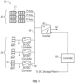
- Fig. 1 depicts a distributed solar and storage system 10 which may be deployed as part of a larger array. It is contemplated that this application could be utilized for solar tracker systems, fixed tilt solar systems, roof top solar, and any type of solar array.
- Each distributed solar and storage system 10 includes a single input port inverter 40 which is fed an output voltage from a first power source such as a solar power plant 20, and from a second power source such as a DC storage plant 30, by way of a common bus 50.
- Other types of power sources are contemplated such as steam, nuclear, geo-thermal, hydroelectric, wind, etc. It is contemplated that more than two power sources can be utilized.
- the single input port inverter 40 can be sized for the AC output requirements of the grid to which it is connected.
- the common bus 50 allows for near instantaneous response to changes in the system power requirements.
- the DC storage plant 30 typically includes a plurality of battery banks 31, bi-directional DC/DC converters 32, and a controller 60.
- the controller 60 can govern the charge and discharge rate.
- the bi-directional DC/DC converters 32 can be configured to charge the battery banks 31.
- the bi-directional DC/DC converters 32 can be sized to the battery output or input. Every battery bank 31 and DC/DC converter 32 is separately managed.
- the bi-directional DC/DC converters 32 employ a power droop algorithm which maintains constant power output in the normal MPPT region. When the voltage is higher or lower than the MPPT region, a bi-directional DC/DC converter 32 could ramp up power or ramp down power output to the bus 50.
- the power droop algorithm enables local control of power output from the DC power plant 30 based on the external load. Additionally internal resistance of the parallel connected bi-directional DC/DC converters 32 maintains relatively equal current sharing between the battery banks 31.
- the power droop algorithm, in combination with the battery banks 31 and the photovoltaic panel arrays 21 sharing a common bus 50 eliminates the need for additional communication and allows for a fast response to micro-grid applications (e.g., changes in load on the inverter 40).
- the single input port inverter 40 receives power from the common bus 50 and converts it to an AC voltage.
- the single input port inverter 40 can be sized for the AC output requirements of the distributed solar and storage system 10.
- the single input port inverter 40 maintains the output power at the Maximum Power Point (MPP) by using, for example, the voltage tracking method. It is contemplated that other methods known in the art can be used.
- Maximum Power Point Tracking (MPPT) which is the process of finding the keeping the load characteristic at the point where the system is optimized to give the highest power transfer, is run at the input port of the single input port inverter 40. The output power from the solar plant is sampled and the proper load characteristic (resistance) is applied so as to obtain maximum power.
- the single input port inverter 40 When a grid curtailment command arrives at the solar power plant 20 and the DC storage plant 30, the single input port inverter 40 experiences a rise in system voltage at the bus 50, and both the solar power plant 20 and the DC storage plant 30 reduce power output without active control. Similarly, in an increasing load scenario, the single input port inverter 40 experiences a drop in system voltage at the bus 50, and both the solar power plant 20 and the DC storage plant 30 increases power output without an active control. These changes in voltage are near instantaneous at the single input port inverter 40.
- the controller 60 can communicate with the individual bi-directional DC/DC converters to manage the output of each of the individual battery banks 31 to achieve the same power and current output in a more efficient manner and in accordance with the health and states of charge of each of the individual battery banks 31 as described in greater detail below. It is contemplated that the battery banks 31 and DC/DC converters 32 are separately managed.
- the single input port inverter 40 is thus able to maintain power output of the solar power plant 20 and the DC storage plant 30 in the MPPT region.
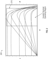
- Fig. 2 depicts a graph 200 depicting the MPPT region of a distributed solar and storage system 10 in accordance with the present disclosure.
- MPPT can be implemented generally to sources with variable power.
- the graph 200 depicts a series of V/I and P/V curves.
- the photovoltaic panel arrays 21 of the solar power plant 20 are equipped with a system for calculating and maintaining MPPT.
- the load characteristic which provides the maximum power transfer efficiency also changes. By changing the load and supply characteristic, the power transfer can be kept at a point of high efficiency.
- the distributed solar and storage system 10 depicted in Fig. 1 will operate such that the single input port inverter 40 can operate within the MPPT region, and simply add or shed supplied power in response to the demand.
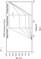
- Fig. 3 depicts a graph of bi-directional DC/DC converter output curve 300 in accordance with the present disclosure.
- the curve depicts output power vs voltage.
- the power droop algorithm employed by the bi-directional DC/DC converters 32 and inverter 40 maintains the output at a relatively constant power.
- a constant power region 310 depicts the power output of the DC/DC converters 32 at a given voltage. Though relatively constant, a droop in power is depicted as the voltage increases.
- the constant power region 310 of the graph 300 substantially overlaps the MPPT region 210 of Fig. 2 .
- the bi-directional DC/DC converter can automatically react and increase its output voltage, as depicted in Fig. 3 , to a point higher than the MPPT region depicted in Fig. 2 .
- the bi-directional DC/DC converter can automatically react and the output power can be ramped up. This allows the bi-directional DC/DC converters 32 to respond changes in load automatically as a result of changes in current drawn from the battery banks 31 to maintain the inverter 40 at or near MPPT at all times.
- the controller 60 though lagging the near instantaneous response caused by the changes in bus 50 voltage caused by the change in load, is able to communicate with the bi-directional DC/DC converters to adjust how that reduced or increased power is being delivered to the common bus 50. That is the controller can adjust which battery banks 31 are actually feeding the common bus 50. In this way, controller can remove battery banks 31 from the common bus 50 to both adjust the delivered power, and to reduce the bus voltage, shifting the operating point of the inverter 40 to within the inverter nominal operating region, and to a more efficient point on the MPPT curves depicted in Fig. 2 .
- the response to load by the bi-directional DC /DC converters 32 both connecting to or separating from the common bus 50 is initially driven by the bus voltage. Secondarily it is driven by the controller 60 to manage more directly which battery banks 31 and bi-directional DC/DC converters 32 are supplying power to the common bus 50 and inverter 40 or are being charged by the solar power plant 20.
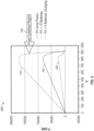
- Fig. 4 depicts a graph of grid demand response 400 in accordance with the present disclosure.
- an 80kW solar power plant and ten 10kW batteries sharing the common bus 50 could have all the battery banks 31 running full discharge as in the top trace in the graph 400.
- the system 10 maintains output power in the MPPT region as depicted in Fig. 2 .
- By turning off all of the batteries 31, only the solar power plant 20 would remain providing power to the grid, as in the middle trace 420. If for example, half of the battery banks 31 needed charging the curve would follow the lower trace 430.
- the distributed solar and storage system 10 would attempt to remain operating in the MPPT region as depicted in Fig.
- the single input port inverter 40 will still be able to provide maximum power. If the single input port inverter 40 voltage rises past the MPPT region and into the power curtailment region of the graph 400 in any of the above traces 410, 420, 430, the solar power plant 20 and the DC storage plant 30 will automatically respond by reducing power to the common bus 50, without the need for a command.
- the AC load demand when the AC load demand changes, it creates a change in frequency, which will translate as a change in bus voltage on the input side of the single input port inverter 40.
- the single input port inverter 40 When the grid frequency is low, and there is a need for frequency support, the single input port inverter 40 will reduce the system voltage on the common bus 50 to search for the system maximum power.
- Fig. 5 depicts a logic flow for a control algorithm in accordance with the present disclosure.
- the system controller 60 can monitor the power demand of a particular load at step 510.
- the controller 60 can monitor the DC charging state of the DC storage plant 30 at step 520, and monitor the output power and voltage of the solar power plant 20 at step 530.
- the controller 60 can detect whether the load has increased 540, and after the load has stabilized, the controller 60 can adjust at step 550 the power available from the DC storage plant 30 in accordance with the power droop algorithm.
- the controller 60 can detect or receive communications indicating at step 560 that there are one or more bad batteries in a battery bank 31.
- a bad battery can cause the entire battery bank 31 to be bad and thus unavailable for meeting load demands safely.
- the controller can switch the affected battery bank 31 off, preventing it from being employed to respond to changing load demands, and ensure that any battery bank 31 with a faulty battery is not permitted to be connected to the bus 50 and feed the inverter. It is contemplated that the controller 60 maintains the operating state of charging of the DC storage plant 30 at or above a minimum level of charge.
- the controller 60 can detect whether demand has dropped at step 580. Generally, the response to load by the bi-directional DC /DC converters 32 is initially driven by the bus voltage. However, when the load demand is stabilized, the controller 60 can adjust the amount of power being supplied from the DC storage plant 30. It is contemplated that any of the detecting steps 540, 560, and 580 can happen in parallel with each other.
Landscapes
- Engineering & Computer Science (AREA)
- Power Engineering (AREA)
- Physics & Mathematics (AREA)
- General Physics & Mathematics (AREA)
- Automation & Control Theory (AREA)
- Charge And Discharge Circuits For Batteries Or The Like (AREA)
- Supply And Distribution Of Alternating Current (AREA)
- Photovoltaic Devices (AREA)
Claims (10)
- Un procédé pour mettre en oeuvre un système de stockage et de génération d'énergie distribuée multi-puissance comprenant :alimenter directement un bus commun (50) avec l'énergie générée par une pluralité de panneaux solaires (21, 610) d'une centrale solaire (20) ;décharger, par une pluralité de convertisseurs bidirectionnels DC/DC (32) d'une centrale de stockage DC (30), l'énergie d'au moins une pluralité de banques de batteries (31), respectivement, directement vers le bus commun (50) ;alimenter une tension sur le bus commun (50) à un onduleur à port d'entrée unique (40) ;surveiller (510), par un contrôleur de système (60), une demande de puissance d'une charge externe ;maintenir une sortie de puissance constante de la centrale de stockage DC (30) dans une région de suivi du point de puissance maximale, MPPT, (210) de la centrale solaire (20) en utilisant la méthode de réduction de puissance permettant un contrôle local de la sortie de puissance de la centrale de stockage DC (30) basé sur la demande de puissance de la charge externe ;réduire progressivement une puissance de sortie de la pluralité de convertisseurs bidirectionnels DC/DC (32) lorsque la tension sur le bus commun (50) est supérieure à la région MPPT (210) ;augmenter progressivement une puissance de sortie de la pluralité de convertisseurs bidirectionnels DC/DC (32) lorsque la tension sur le bus commun (50) est inférieure à la région MPPT (210) ; etmaintenir une puissance de sortie maximale de la centrale solaire (20).
- Le procédé selon la revendication 1, comprenant en outre :surveiller avec un contrôleur (60) une demande de puissance d'une charge ;surveiller avec le contrôleur (60) un état de santé de charge DC des batteries de la centrale de stockage DC (30) ;surveiller avec le contrôleur (60) la puissance de sortie et la tension de la centrale solaire (20) ; etoù, lorsque la demande de charge est stabilisée, le contrôleur (60) détermine laquelle des pluralités de banques de batteries (31) doit fournir de la puissance de sortie au bus commun (50).
- Un système de stockage distribué multi-puissance (10) comprenant :une première source d'énergie connectée électriquement et directement à un bus commun (50) ;une deuxième source d'énergie connectée électriquement et directement au bus commun (50) ;un onduleur à port d'entrée unique (40) connecté électriquement au bus commun (50) ; etun contrôleur de système (60) configuré pour communiquer avec au moins la deuxième source d'énergie et l'onduleur à port d'entrée unique (40), et en outre configuré pour surveiller une demande de puissance d'une charge externe,où la première source d'énergie comprend une centrale solaire (20) comprenant une pluralité de panneaux solaires (21, 610),où la deuxième source d'énergie comprend une centrale de stockage DC (30) comprenant une pluralité de banques de batteries (31) et une pluralité de convertisseurs bidirectionnels DC/DC (32) configurés pour charger et décharger la pluralité de banques de batteries (31),où, lorsqu'une commande de réduction de puissance du réseau est reçue à l'onduleur à port d'entrée unique (40), une tension du bus commun (50) augmente et la deuxième source d'énergie réduit la puissance de sortie en réponse à l'augmentation de la tension du bus commun (50),où, lorsqu'une charge augmente, la tension du bus commun (50) diminue et la deuxième source d'énergie augmente la puissance de sortie, etoù, lors du maintien d'une puissance constante, la sortie de puissance constante de la centrale de stockage DC (30) est maintenue en utilisant une méthode de réduction de puissance permettant un contrôle local de la sortie de puissance de la centrale de stockage DC (30) basé sur la demande de puissance de la charge externe.
- Le système selon la revendication 3, où la première source d'énergie comprend une centrale solaire (20).
- Le système selon la revendication 4, où la centrale solaire (20) est configurée pour utiliser le MPPT (210) pour maintenir une puissance de sortie maximale.
- Le système selon la revendication 4, où la centrale solaire (20) comprend une pluralité de panneaux solaires (21, 610).
- Le système (10) selon la revendication 3, la centrale de stockage DC (30) comprenant en outre :
un contrôleur (60) comprenant au moins un processeur, et une mémoire ayant des instructions stockées qui, lorsqu'elles sont exécutées par ledit au moins un processeur, communiquent avec les convertisseurs bidirectionnels DC/DC (32) pour ajuster les banques de batteries (31) fournissant de l'énergie au bus commun (50). - Le système (10) selon la revendication 7, où chaque banque de batteries (31) est gérée séparément.
- Le système (10) selon la revendication 8, où les banques de batteries (31) sont configurées pour fournir de l'énergie au bus commun (50) pour maintenir la forme de la courbe de puissance PV, permettant à l'onduleur à port d'entrée unique de fonctionner au MPPT (210).
- Le système (10) selon la revendication 7, où le contrôleur (60) est en outre configuré pour maintenir l'état de fonctionnement de la charge de la centrale de stockage DC (30) à un niveau de charge minimum ou supérieur.
Priority Applications (1)
| Application Number | Priority Date | Filing Date | Title |
|---|---|---|---|
| EP24209554.5A EP4475374A3 (fr) | 2018-04-27 | 2019-04-18 | Convertisseur cc/cc pour systèmes de stockage et solaires distribués |
Applications Claiming Priority (2)
| Application Number | Priority Date | Filing Date | Title |
|---|---|---|---|
| US15/965,108 US10951040B2 (en) | 2018-04-27 | 2018-04-27 | DC/DC converter for distributed storage and solar systems |
| PCT/US2019/028176 WO2019209627A1 (fr) | 2018-04-27 | 2019-04-18 | Convertisseur cc/cc pour systèmes solaires et de stockage distribué |
Related Child Applications (1)
| Application Number | Title | Priority Date | Filing Date |
|---|---|---|---|
| EP24209554.5A Division EP4475374A3 (fr) | 2018-04-27 | 2019-04-18 | Convertisseur cc/cc pour systèmes de stockage et solaires distribués |
Publications (4)
| Publication Number | Publication Date |
|---|---|
| EP3785342A1 EP3785342A1 (fr) | 2021-03-03 |
| EP3785342A4 EP3785342A4 (fr) | 2022-05-11 |
| EP3785342B1 true EP3785342B1 (fr) | 2024-10-30 |
| EP3785342C0 EP3785342C0 (fr) | 2024-10-30 |
Family
ID=68292677
Family Applications (2)
| Application Number | Title | Priority Date | Filing Date |
|---|---|---|---|
| EP24209554.5A Pending EP4475374A3 (fr) | 2018-04-27 | 2019-04-18 | Convertisseur cc/cc pour systèmes de stockage et solaires distribués |
| EP19792495.4A Active EP3785342B1 (fr) | 2018-04-27 | 2019-04-18 | Convertisseur cc/cc pour systèmes solaires et de stockage distribué |
Family Applications Before (1)
| Application Number | Title | Priority Date | Filing Date |
|---|---|---|---|
| EP24209554.5A Pending EP4475374A3 (fr) | 2018-04-27 | 2019-04-18 | Convertisseur cc/cc pour systèmes de stockage et solaires distribués |
Country Status (7)
| Country | Link |
|---|---|
| US (3) | US10951040B2 (fr) |
| EP (2) | EP4475374A3 (fr) |
| CN (1) | CN112119558B (fr) |
| AU (3) | AU2019260587B2 (fr) |
| ES (1) | ES3012981T3 (fr) |
| PL (1) | PL3785342T3 (fr) |
| WO (1) | WO2019209627A1 (fr) |
Families Citing this family (23)
| Publication number | Priority date | Publication date | Assignee | Title |
|---|---|---|---|---|
| EP3616289B1 (fr) * | 2017-05-31 | 2021-04-14 | General Electric Company | Système et procédé de commande destinés à un système de stockage d'énergie |
| CN112075004B (zh) * | 2018-05-04 | 2024-08-23 | 奈克斯跟踪器有限公司 | 用于太阳能领域的dc功率转换和传输的系统和方法 |
| US11183938B2 (en) | 2018-11-14 | 2021-11-23 | Toshiba International Corporation | Hybrid PV inverter with SCIB battery integration |
| CN110943478B (zh) * | 2019-11-22 | 2022-09-09 | 东北电力大学 | 可再生能源发电系统输出功率利用率最大化控制方法 |
| CN111224392A (zh) * | 2020-01-03 | 2020-06-02 | 云南电网有限责任公司电力科学研究院 | 一种三端口直流能量路由器功率协调控制方法 |
| CN111181194B (zh) * | 2020-01-09 | 2021-03-30 | 中国科学院电工研究所 | 一种含分布式能源的交直流配用电系统智能协调管控方法 |
| WO2021173136A1 (fr) * | 2020-02-27 | 2021-09-02 | General Electric Company | Système et procédé de commande d'un système de stockage d'énergie renouvelable hybride. |
| CN111478360A (zh) * | 2020-03-20 | 2020-07-31 | 国网浙江省电力有限公司电力科学研究院 | 含光伏接入的配电网集中-就地综合电压控制方法和装置 |
| CN111446735B (zh) | 2020-04-07 | 2022-01-28 | 清华大学 | 用于光伏中压集散系统的控制系统及方法 |
| CN113644726B (zh) | 2020-04-27 | 2025-04-08 | 台达电子企业管理(上海)有限公司 | 分布式供电系统及基于其的能量调节方法 |
| AU2020454251A1 (en) | 2020-06-17 | 2022-04-21 | Huawei Digital Power Technologies Co., Ltd. | Electrical energy storage system and energy storage system |
| CN115699493A (zh) * | 2020-06-30 | 2023-02-03 | 古河电气工业株式会社 | 电力变换器、电力变换器的控制方法、电力系统、电力系统的控制方法及程序 |
| CN112072705A (zh) * | 2020-09-22 | 2020-12-11 | 珠海冠宇动力电池有限公司 | 一种发电储能系统 |
| CN112467779B (zh) * | 2020-11-18 | 2023-04-07 | 西安热工研究院有限公司 | 一种消除多端柔性直流输电控制系统稳态电压偏差的方法 |
| CN115085245A (zh) * | 2021-03-10 | 2022-09-20 | 台达电子工业股份有限公司 | 光伏储能系统及其适用的控制方法 |
| WO2022198635A1 (fr) * | 2021-03-26 | 2022-09-29 | 华为数字能源技术有限公司 | Système de stockage d'énergie et procédé de commande associé |
| CN118017631A (zh) * | 2021-03-31 | 2024-05-10 | 华为数字能源技术有限公司 | 一种储能系统 |
| AU2022308363A1 (en) * | 2021-07-08 | 2024-01-18 | Nextpower Llc | Common dc bus and common ac bus power electronics systems and methods |
| KR102793991B1 (ko) | 2021-10-06 | 2025-04-09 | 주식회사 엘지에너지솔루션 | 태양광 시스템과 연계하는 에너지 저장 시스템 및 에너지 저장 시스템의 제어 방법 |
| EP4329131A4 (fr) * | 2022-01-26 | 2025-01-08 | Lg Energy Solution, Ltd. | Système de gestion d'énergie de type à connexion directe pv-ess et dispositif d'interfonctionnement de système de génération d'énergie photovoltaïque |
| US20240030716A1 (en) * | 2022-07-21 | 2024-01-25 | GE Grid GmbH | Systems and methods for overload control in renewable power systems |
| CN120386422A (zh) * | 2024-01-29 | 2025-07-29 | 安克创新科技股份有限公司 | 光伏储能设备输出功率调节方法、系统和光伏储能设备 |
| CN120237696B (zh) * | 2025-05-30 | 2025-11-21 | 锦浪科技股份有限公司 | 一种多路电池接口的多模式储能系统 |
Family Cites Families (17)
| Publication number | Priority date | Publication date | Assignee | Title |
|---|---|---|---|---|
| US8159178B2 (en) | 2009-08-21 | 2012-04-17 | Xantrex Technology Inc. | AC connected modules with line frequency or voltage variation pattern for energy control |
| KR101116483B1 (ko) * | 2009-12-04 | 2012-02-27 | 삼성에스디아이 주식회사 | 에너지 저장 시스템 |
| KR101084215B1 (ko) | 2009-12-16 | 2011-11-17 | 삼성에스디아이 주식회사 | 에너지 저장 시스템 및 이의 제어 방법 |
| US9853565B2 (en) | 2012-01-30 | 2017-12-26 | Solaredge Technologies Ltd. | Maximized power in a photovoltaic distributed power system |
| GB2498790A (en) * | 2012-01-30 | 2013-07-31 | Solaredge Technologies Ltd | Maximising power in a photovoltaic distributed power system |
| WO2013163350A1 (fr) | 2012-04-25 | 2013-10-31 | Inovus Solar, Inc. | Optimisation de la production d'énergie par un panneau photovoltaïque courbe |
| KR20130138611A (ko) * | 2012-06-11 | 2013-12-19 | 삼성에스디아이 주식회사 | 에너지 저장 시스템 |
| US9748772B2 (en) * | 2013-02-14 | 2017-08-29 | Abb Schweiz Ag | Method of controlling a solar power plant, a power conversion system, a DC/AC inverter and a solar power plant |
| CN105207258B (zh) * | 2013-10-11 | 2019-06-04 | 国网河南省电力公司南阳供电公司 | 一种光伏直流微电网能量协调控制装置 |
| GB2535132A (en) * | 2014-10-09 | 2016-08-17 | Isis Innovation | Electrical energy storage device |
| WO2016134319A1 (fr) | 2015-02-19 | 2016-08-25 | Enphase Energy, Inc. | Procédé et appareil destinés à une commande de flexion en charge dans le domaine temporel comportant une commande de courant de phaseur intégrée |
| WO2016191264A1 (fr) * | 2015-05-22 | 2016-12-01 | Tigo Energy, Inc. | Systèmes et procédés pour une dissipation rapide de l'énergie stockée provenant de condensateurs d'entrée d'onduleurs de puissance |
| US20170077709A1 (en) | 2015-09-15 | 2017-03-16 | Abb Technology Ltd. | Pv system having distributed dc-dc converters |
| WO2017173246A1 (fr) | 2016-03-31 | 2017-10-05 | Flex Ltd. | Plateforme de conteneur de stockage d'énergie standard |
| CN107394829B (zh) * | 2016-05-17 | 2022-06-07 | 中国电力科学研究院 | 一种基于无互联通信的直流供电系统协调控制系统及方法 |
| CN106505616B (zh) * | 2016-11-17 | 2018-12-18 | 华北电力大学(保定) | 一种直流配电网直流电压的调节方法 |
| US20180337385A1 (en) | 2017-05-17 | 2018-11-22 | Flex Ltd. | Direct current battery string aggregator for standard energy storage enclosure platform |
-
2018
- 2018-04-27 US US15/965,108 patent/US10951040B2/en active Active
-
2019
- 2019-04-18 WO PCT/US2019/028176 patent/WO2019209627A1/fr not_active Ceased
- 2019-04-18 ES ES19792495T patent/ES3012981T3/es active Active
- 2019-04-18 CN CN201980028303.5A patent/CN112119558B/zh active Active
- 2019-04-18 EP EP24209554.5A patent/EP4475374A3/fr active Pending
- 2019-04-18 EP EP19792495.4A patent/EP3785342B1/fr active Active
- 2019-04-18 PL PL19792495.4T patent/PL3785342T3/pl unknown
- 2019-04-18 AU AU2019260587A patent/AU2019260587B2/en active Active
-
2021
- 2021-03-15 US US17/202,331 patent/US11804721B2/en active Active
- 2021-10-26 AU AU2021257945A patent/AU2021257945B2/en active Active
-
2023
- 2023-10-05 US US18/481,635 patent/US12519323B2/en active Active
- 2023-10-05 AU AU2023241337A patent/AU2023241337B2/en active Active
Also Published As
| Publication number | Publication date |
|---|---|
| CN112119558A (zh) | 2020-12-22 |
| ES3012981T3 (en) | 2025-04-10 |
| US20190334349A1 (en) | 2019-10-31 |
| EP3785342C0 (fr) | 2024-10-30 |
| EP3785342A1 (fr) | 2021-03-03 |
| EP3785342A4 (fr) | 2022-05-11 |
| WO2019209627A1 (fr) | 2019-10-31 |
| AU2023241337A1 (en) | 2023-10-26 |
| AU2021257945B2 (en) | 2023-07-06 |
| US20240030725A1 (en) | 2024-01-25 |
| PL3785342T3 (pl) | 2025-03-24 |
| AU2023241337B2 (en) | 2025-04-24 |
| EP4475374A3 (fr) | 2025-03-12 |
| US10951040B2 (en) | 2021-03-16 |
| AU2019260587A1 (en) | 2020-10-22 |
| AU2019260587B2 (en) | 2021-08-05 |
| CN112119558B (zh) | 2024-12-31 |
| US20210296904A1 (en) | 2021-09-23 |
| US12519323B2 (en) | 2026-01-06 |
| US11804721B2 (en) | 2023-10-31 |
| EP4475374A2 (fr) | 2024-12-11 |
| AU2021257945A1 (en) | 2021-11-25 |
Similar Documents
| Publication | Publication Date | Title |
|---|---|---|
| EP3785342B1 (fr) | Convertisseur cc/cc pour systèmes solaires et de stockage distribué | |
| US9502904B2 (en) | Power conversion system and method providing maximum efficiency of power conversion for a photovoltaic system, and photovoltaic system employing a photovoltaic array and an energy storage device | |
| US10404072B2 (en) | Method and apparatus for bidirectional storage and renewable power converter | |
| EP2424066B1 (fr) | Système et procédé de distribution de support d'énergie réactive avec un onduleur | |
| US9800051B2 (en) | Method and apparatus for controlling energy flow between dissimilar energy storage devices | |
| EP2289162B1 (fr) | Systeme de stockage maximisant l'utilisation d'energie renouvelable | |
| US20160329719A1 (en) | Solar power generation system | |
| US8263276B1 (en) | Startup power control in a fuel cell system | |
| US20170093187A1 (en) | Energy storage system | |
| Zubieta | Power management and optimization concept for DC microgrids | |
| CN104836247B (zh) | 实现储能容量动态优化的光储微网系统 | |
| US20220368132A1 (en) | Microgrid controllers and associated methodologies | |
| WO2013175612A1 (fr) | Système d'alimentation électrique | |
| WO2016084400A1 (fr) | Système d'accumulateur et procédé de stockage d'électricité | |
| Sorouri et al. | Autonomous active power control for an islanded AC microgrid using improved bus signaling method | |
| AU2024266858B2 (en) | Direct-current coupling system and charging control method therefor | |
| JP2021197823A (ja) | 直流マイクログリッドシステム及びその制御方法 | |
| CN113364052A (zh) | 一种基于能量枢纽综合能源的运行决策系统 | |
| Mirzabaev et al. | Experience in implementing modern energy storage systems in Uzbekistan | |
| Cai et al. | Decentralized autonomous operation for islanded photovoltaic-based DC microgrids | |
| CN113364053B (zh) | 一种实现能量枢纽综合能源的运行决策方法 | |
| JP2024162248A (ja) | 電力融通システム | |
| CN114784786A (zh) | 一种直流母线电压的控制方法、装置、直流微电网系统及存储介质 | |
| CN120855490A (zh) | 基于自适应分段构网的光储微电网离网自治控制方法 | |
| WO2017195213A1 (fr) | Intégration de blocs d'alimentation multiples avec optimisation du bloc d'alimentation et des conditions de charge |
Legal Events
| Date | Code | Title | Description |
|---|---|---|---|
| STAA | Information on the status of an ep patent application or granted ep patent |
Free format text: STATUS: THE INTERNATIONAL PUBLICATION HAS BEEN MADE |
|
| PUAI | Public reference made under article 153(3) epc to a published international application that has entered the european phase |
Free format text: ORIGINAL CODE: 0009012 |
|
| STAA | Information on the status of an ep patent application or granted ep patent |
Free format text: STATUS: REQUEST FOR EXAMINATION WAS MADE |
|
| 17P | Request for examination filed |
Effective date: 20201124 |
|
| AK | Designated contracting states |
Kind code of ref document: A1 Designated state(s): AL AT BE BG CH CY CZ DE DK EE ES FI FR GB GR HR HU IE IS IT LI LT LU LV MC MK MT NL NO PL PT RO RS SE SI SK SM TR |
|
| AX | Request for extension of the european patent |
Extension state: BA ME |
|
| DAV | Request for validation of the european patent (deleted) | ||
| DAX | Request for extension of the european patent (deleted) | ||
| A4 | Supplementary search report drawn up and despatched |
Effective date: 20220411 |
|
| RIC1 | Information provided on ipc code assigned before grant |
Ipc: H02J 3/28 20060101ALI20220405BHEP Ipc: H02J 3/00 20060101AFI20220405BHEP |
|
| REG | Reference to a national code |
Ref country code: DE Free format text: PREVIOUS MAIN CLASS: H02J0003000000 Ref country code: DE Ref legal event code: R079 Ref document number: 602019061194 Country of ref document: DE Free format text: PREVIOUS MAIN CLASS: H02J0003000000 Ipc: H02J0003380000 |
|
| GRAP | Despatch of communication of intention to grant a patent |
Free format text: ORIGINAL CODE: EPIDOSNIGR1 |
|
| STAA | Information on the status of an ep patent application or granted ep patent |
Free format text: STATUS: GRANT OF PATENT IS INTENDED |
|
| RIC1 | Information provided on ipc code assigned before grant |
Ipc: H02J 3/32 20060101ALN20240513BHEP Ipc: H02J 1/10 20060101ALN20240513BHEP Ipc: H02J 7/35 20060101ALN20240513BHEP Ipc: H02J 3/38 20060101AFI20240513BHEP |
|
| INTG | Intention to grant announced |
Effective date: 20240529 |
|
| RIC1 | Information provided on ipc code assigned before grant |
Ipc: H02J 3/32 20060101ALN20240521BHEP Ipc: H02J 1/10 20060101ALN20240521BHEP Ipc: H02J 7/35 20060101ALN20240521BHEP Ipc: H02J 3/38 20060101AFI20240521BHEP |
|
| GRAS | Grant fee paid |
Free format text: ORIGINAL CODE: EPIDOSNIGR3 |
|
| GRAA | (expected) grant |
Free format text: ORIGINAL CODE: 0009210 |
|
| STAA | Information on the status of an ep patent application or granted ep patent |
Free format text: STATUS: THE PATENT HAS BEEN GRANTED |
|
| AK | Designated contracting states |
Kind code of ref document: B1 Designated state(s): AL AT BE BG CH CY CZ DE DK EE ES FI FR GB GR HR HU IE IS IT LI LT LU LV MC MK MT NL NO PL PT RO RS SE SI SK SM TR |
|
| REG | Reference to a national code |
Ref country code: GB Ref legal event code: FG4D |
|
| REG | Reference to a national code |
Ref country code: CH Ref legal event code: EP |
|
| REG | Reference to a national code |
Ref country code: IE Ref legal event code: FG4D |
|
| REG | Reference to a national code |
Ref country code: DE Ref legal event code: R096 Ref document number: 602019061194 Country of ref document: DE |
|
| U01 | Request for unitary effect filed |
Effective date: 20241129 |
|
| U07 | Unitary effect registered |
Designated state(s): AT BE BG DE DK EE FI FR IT LT LU LV MT NL PT RO SE SI Effective date: 20241209 |
|
| REG | Reference to a national code |
Ref country code: GR Ref legal event code: EP Ref document number: 20250400211 Country of ref document: GR Effective date: 20250314 |
|
| REG | Reference to a national code |
Ref country code: ES Ref legal event code: FG2A Ref document number: 3012981 Country of ref document: ES Kind code of ref document: T3 Effective date: 20250410 |
|
| PG25 | Lapsed in a contracting state [announced via postgrant information from national office to epo] |
Ref country code: HR Free format text: LAPSE BECAUSE OF FAILURE TO SUBMIT A TRANSLATION OF THE DESCRIPTION OR TO PAY THE FEE WITHIN THE PRESCRIBED TIME-LIMIT Effective date: 20241030 Ref country code: IS Free format text: LAPSE BECAUSE OF FAILURE TO SUBMIT A TRANSLATION OF THE DESCRIPTION OR TO PAY THE FEE WITHIN THE PRESCRIBED TIME-LIMIT Effective date: 20250228 |
|
| PG25 | Lapsed in a contracting state [announced via postgrant information from national office to epo] |
Ref country code: RS Free format text: LAPSE BECAUSE OF FAILURE TO SUBMIT A TRANSLATION OF THE DESCRIPTION OR TO PAY THE FEE WITHIN THE PRESCRIBED TIME-LIMIT Effective date: 20250130 |
|
| U20 | Renewal fee for the european patent with unitary effect paid |
Year of fee payment: 7 Effective date: 20250428 |
|
| PG25 | Lapsed in a contracting state [announced via postgrant information from national office to epo] |
Ref country code: SM Free format text: LAPSE BECAUSE OF FAILURE TO SUBMIT A TRANSLATION OF THE DESCRIPTION OR TO PAY THE FEE WITHIN THE PRESCRIBED TIME-LIMIT Effective date: 20241030 |
|
| PGFP | Annual fee paid to national office [announced via postgrant information from national office to epo] |
Ref country code: GB Payment date: 20250428 Year of fee payment: 7 Ref country code: ES Payment date: 20250505 Year of fee payment: 7 |
|
| PGFP | Annual fee paid to national office [announced via postgrant information from national office to epo] |
Ref country code: NO Payment date: 20250429 Year of fee payment: 7 |
|
| PGFP | Annual fee paid to national office [announced via postgrant information from national office to epo] |
Ref country code: GR Payment date: 20250430 Year of fee payment: 7 |
|
| PGFP | Annual fee paid to national office [announced via postgrant information from national office to epo] |
Ref country code: CH Payment date: 20250501 Year of fee payment: 7 |
|
| PG25 | Lapsed in a contracting state [announced via postgrant information from national office to epo] |
Ref country code: SK Free format text: LAPSE BECAUSE OF FAILURE TO SUBMIT A TRANSLATION OF THE DESCRIPTION OR TO PAY THE FEE WITHIN THE PRESCRIBED TIME-LIMIT Effective date: 20241030 |
|
| PGFP | Annual fee paid to national office [announced via postgrant information from national office to epo] |
Ref country code: CZ Payment date: 20250407 Year of fee payment: 7 |
|
| PLBE | No opposition filed within time limit |
Free format text: ORIGINAL CODE: 0009261 |
|
| STAA | Information on the status of an ep patent application or granted ep patent |
Free format text: STATUS: NO OPPOSITION FILED WITHIN TIME LIMIT |
|
| 26N | No opposition filed |
Effective date: 20250731 |
|
| PG25 | Lapsed in a contracting state [announced via postgrant information from national office to epo] |
Ref country code: MC Free format text: LAPSE BECAUSE OF FAILURE TO SUBMIT A TRANSLATION OF THE DESCRIPTION OR TO PAY THE FEE WITHIN THE PRESCRIBED TIME-LIMIT Effective date: 20241030 |
|
| PG25 | Lapsed in a contracting state [announced via postgrant information from national office to epo] |
Ref country code: IE Free format text: LAPSE BECAUSE OF NON-PAYMENT OF DUE FEES Effective date: 20250418 |
|
| PGFP | Annual fee paid to national office [announced via postgrant information from national office to epo] |
Ref country code: TR Payment date: 20260331 Year of fee payment: 8 |
|
| PGFP | Annual fee paid to national office [announced via postgrant information from national office to epo] |
Ref country code: PL Payment date: 20260323 Year of fee payment: 8 |