EP3785452B1 - Vorrichtung und verfahren zur wiedergabe eines audiosignals zur wiedergabe an einen benutzer - Google Patents
Vorrichtung und verfahren zur wiedergabe eines audiosignals zur wiedergabe an einen benutzer Download PDFInfo
- Publication number
- EP3785452B1 EP3785452B1 EP19717951.8A EP19717951A EP3785452B1 EP 3785452 B1 EP3785452 B1 EP 3785452B1 EP 19717951 A EP19717951 A EP 19717951A EP 3785452 B1 EP3785452 B1 EP 3785452B1
- Authority
- EP
- European Patent Office
- Prior art keywords
- head
- orientation
- user
- information
- optical sensor
- Prior art date
- Legal status (The legal status is an assumption and is not a legal conclusion. Google has not performed a legal analysis and makes no representation as to the accuracy of the status listed.)
- Active
Links
Images


Classifications
-
- H—ELECTRICITY
- H04—ELECTRIC COMMUNICATION TECHNIQUE
- H04S—STEREOPHONIC SYSTEMS
- H04S7/00—Indicating arrangements; Control arrangements, e.g. balance control
- H04S7/30—Control circuits for electronic adaptation of the sound field
- H04S7/302—Electronic adaptation of stereophonic sound system to listener position or orientation
- H04S7/303—Tracking of listener position or orientation
- H04S7/304—For headphones
-
- G—PHYSICS
- G06—COMPUTING OR CALCULATING; COUNTING
- G06F—ELECTRIC DIGITAL DATA PROCESSING
- G06F3/00—Input arrangements for transferring data to be processed into a form capable of being handled by the computer; Output arrangements for transferring data from processing unit to output unit, e.g. interface arrangements
- G06F3/01—Input arrangements or combined input and output arrangements for interaction between user and computer
- G06F3/011—Arrangements for interaction with the human body, e.g. for user immersion in virtual reality
- G06F3/012—Head tracking input arrangements
-
- G—PHYSICS
- G06—COMPUTING OR CALCULATING; COUNTING
- G06F—ELECTRIC DIGITAL DATA PROCESSING
- G06F3/00—Input arrangements for transferring data to be processed into a form capable of being handled by the computer; Output arrangements for transferring data from processing unit to output unit, e.g. interface arrangements
- G06F3/16—Sound input; Sound output
- G06F3/167—Audio in a user interface, e.g. using voice commands for navigating, audio feedback
-
- G—PHYSICS
- G06—COMPUTING OR CALCULATING; COUNTING
- G06T—IMAGE DATA PROCESSING OR GENERATION, IN GENERAL
- G06T13/00—Animation
- G06T13/20—Three-dimensional [3D] animation
- G06T13/205—Three-dimensional [3D] animation driven by audio data
-
- H—ELECTRICITY
- H04—ELECTRIC COMMUNICATION TECHNIQUE
- H04S—STEREOPHONIC SYSTEMS
- H04S7/00—Indicating arrangements; Control arrangements, e.g. balance control
- H04S7/30—Control circuits for electronic adaptation of the sound field
- H04S7/302—Electronic adaptation of stereophonic sound system to listener position or orientation
- H04S7/303—Tracking of listener position or orientation
-
- H—ELECTRICITY
- H04—ELECTRIC COMMUNICATION TECHNIQUE
- H04S—STEREOPHONIC SYSTEMS
- H04S2400/00—Details of stereophonic systems covered by H04S but not provided for in its groups
- H04S2400/01—Multi-channel, i.e. more than two input channels, sound reproduction with two speakers wherein the multi-channel information is substantially preserved
Definitions
- the present invention relates to an apparatus for rendering an audio signal, more specifically, an apparatus which is configured to perform a spatial rendering or sound field rendering of the audio signal of acoustic communication.
- Spatial audio processing for binaural rendering of spatial audio data has been widely adopted for headphone use in video gaming and virtual reality (VR), but yet to break into other applications such as audio communications, e.g., voice calls, conferencing and standard video consumption (i.e., non-360 degree).
- audio communications e.g., voice calls, conferencing and standard video consumption (i.e., non-360 degree).
- audio communications e.g., voice calls, conferencing and standard video consumption (i.e., non-360 degree).
- Some applications using static binaural rendering of spatial audio data exist user acceptance seems limited. The reason behind this is hypothesized to be that for spatial audio to be convincing, live positional information of the user's perspective must be actively applied during spatial processing. In order for the brain to be successfully tricked, the audio must respond with low latency to even the smallest of adjustments of the head position.
- the remote participant(s)/user(s) can be rendered as a mono object (per participant/user), each with a unique three-dimensional position (e.g., spread out horizontally in front of the participant/user as listener) in order to give a realistic same-room feeling.
- VR experiences with headphones achieve this using head tracking data (e.g., in the form of pitch angle, yaw angle, roll angle or as quaternions) obtained from inertial measurement units (IMU), including data from sensors, e.g., gyroscopes and accelerometers within the user's head-mounted display (HMD).
- IMU inertial measurement units
- sensors e.g., gyroscopes and accelerometers within the user's head-mounted display (HMD).
- US 2015/382130 A1 discloses a system for obtaining an image of an individual wearing a headset, determining a head orientation of the individual based on the image, and adjusting the soundscape, e.g., adjusting one or more of an audio delivery time difference between left and right channels of the soundscape.
- an apparatus comprises an optical sensor and an orientation sensor for determining a head position of a user. Therefore, an apparatus, e.g., device is possible to determine the position of the head of the user by referencing the positional relationship between the optical sensor and the orientation sensor, and hence, it is possible to accurately determine the position of the head of the user. In addition, using the accurately determined position of the head of the user, it is possible to implement a low-latency adjustment for the spatial rendering and improve the user experience.
- an apparatus for rendering an audio signal for a playback to a user wherein the apparatus is configured to determine information about an orientation of a head of the user using an optical sensor, e.g. using a camera or using a user-facing moving image capture device, and/or using a depth sensor and/or using a visual face/head tracking sensor, for example, using camera-captured data for head tracking; wherein the apparatus is configured to determine information about an orientation of the optical sensor in an Earth-fixed coordinate system using an orientation sensor, for example, a gyroscope and/or a magnetic field sensor and/or a gravity sensor and/or an accelerometer and/or an optical sensor, etc., which is arranged in a predetermined positional relationship, e.g., mechanical relationship with respect to the optical sensor, for example, to enable the apparatus to be aware of its position and/or orientation in a "real world" or in an Earth-fixed coordinate system; wherein the apparatus is configured to consider the information about the orientation of the optical sensor, e.g. using a camera
- the apparatus is configured to perform a binaural rendering, e.g., for a headset worn by the user, or, e.g., of spatial audio data, in dependence on the information about the orientation of the head of the user, for example, considering a yaw angle or an azimuth angle between a head front direction of the user (e.g. a direction into which the user eyes or nose is pointing) and a direction from the user's head towards the apparatus or towards the optical sensor included within the apparatus, or towards a display of the apparatus, and/or considering a roll angle of the head of the user, and/or considering a pitch angle of the head of the user.
- a binaural rendering e.g., for a headset worn by the user, or, e.g., of spatial audio data
- the apparatus comprises the optical sensor, e.g., a camera or a user-facing moving image capture device, and/or a depth sensor, wherein the optical sensor is arranged to track a head of the user, e.g. a position of the user's face, e.g., when the user is looking at a display of the apparatus.
- the optical sensor e.g., a camera or a user-facing moving image capture device, and/or a depth sensor, wherein the optical sensor is arranged to track a head of the user, e.g. a position of the user's face, e.g., when the user is looking at a display of the apparatus.
- the apparatus is configured to determine, for example, as a part of information about the orientation of the head of the user, a yaw angle information, for example, an angle value or a rotation matrix or a quaternion, describing an angle between a head front direction of the head of the user and a position of the apparatus, or, equivalently, a direction from the user's head to the apparatus or to the optical sensor; and/or wherein the apparatus is configured to determine, for example, as a part of the information about the orientation of the head of the user, a roll angle information, for example, an angle value or a rotation matrix or a quaternion describing a roll angle of the head of the user, e.g., with respect to a vertical direction, e.g.
- a pitch angle information for example, an angle value or a rotation matrix or a quaternion, describing a pitch angle of the head of the user, e.g. with respect to a horizontal alignment.
- the apparatus is configured to determine, for example, as a part of information about the orientation of the head of the user, a yaw angle information ⁇ describing a yaw angle between a head front direction of the head of the user and a position of the apparatus such that the yaw angle information describes an azimuth angle between the head front direction of the head of the user and a direction from the head of the user, e.g.
- the apparatus for example, to the optical sensor included in the apparatus, for example, such that the yaw angle information describes an azimuth position of the apparatus when seen from the head of the user, taking into consideration the head front direction, i.e., the direction towards which the user has turned the head or the direction in which the nose of the user is pointing.
- the head front direction i.e., the direction towards which the user has turned the head or the direction in which the nose of the user is pointing.
- the apparatus is configured to at least partially compensate or correct for a deviation, e.g., angle ⁇ err , between the direction from the head of the user to the apparatus and a direction of an optical axis of the optical sensor, for example, using a processing of an image information obtained from the optical sensor.
- a deviation e.g., angle ⁇ err
- the apparatus is configured to determine, for example, as a part of the information about the orientation of the head of the user a roll angle information ⁇ Head roll describing a roll angle of the head of the user with respect to a vertical direction, e.g. with respect to a direction opposite of gravity, also designated with "up", or e.g.
- the roll angle information describes an angle of a rotation of the head around an axis oriented in the head front direction, for example, in the case of no pitch, an angle between a vertical axis of the head of the user and the vertical direction "up", but preferably independent from a roll angle of the apparatus or of the optical sensor, wherein the roll angle information of the head is used when performing the spatial rendering.
- the apparatus is configured to at least partially compensate a roll angle ⁇ Device roll of the apparatus, or of the optical sensor, e.g. with respect to the vertical direction, on the basis of the information about the orientation of the optical sensor when determining the roll angle information describing the roll angle of the head of the user, or optionally, to at least partially compensate the (whole) orientation of the apparatus or of the optical sensor, for example, such that the spatial rendering remains substantially unchanged if only the apparatus or the optical sensor is rolled but the head does not change its roll angle.
- the apparatus is configured to determine, for example, as a part of the information about the orientation of the head of the user, a pitch angle information ⁇ pitch describing a pitch angle of the head of the user with respect to a horizontal alignment, e.g. with respect to an Earth-fixed coordinate system or with respect to an Earth-fixed horizontal plane, for example, such that the pitch angle information describes an elevation angle of the head-front direction, but preferably independent from a pitch angle of the apparatus or of the optical sensor, wherein the pitch angle information describing the pitch angle of the head is used when performing the spatial rendering.
- a pitch angle information ⁇ pitch describing a pitch angle of the head of the user with respect to a horizontal alignment, e.g. with respect to an Earth-fixed coordinate system or with respect to an Earth-fixed horizontal plane, for example, such that the pitch angle information describes an elevation angle of the head-front direction, but preferably independent from a pitch angle of the apparatus or of the optical sensor, wherein the pitch angle information describing the pitch angle of the head is used when performing the spatial rendering
- the apparatus is configured to at least partially compensate the orientation of the apparatus or of the optical sensor on the basis of the information about the orientation of the optical sensor when determining the pitch angle information of the head of the user, for example, such that the determined pitch angle information represents the pitch angle of the head of the user with respect to an Earth-fixed horizontal plane substantially independent from the position of the apparatus comprising the optical sensor and substantially independent from an alignment or rotation of the apparatus comprising the optical sensor.
- the apparatus is configured to determine the information about the orientation of the head on the basis of information from sensors, preferably only from sensors, arranged within the apparatus or mechanically attached to the apparatus, i.e., without using information from any sensors attached to the head of the user or to a headset.
- the apparatus is configured to determine the information about the orientation of the head on the basis of information from sensors arranged within the apparatus or mechanically attached to the apparatus, and on the basis of one or more additional sensors which are external to the apparatus, e.g. external to the main electronic device comprising the optical sensor and the orientation sensor, wherein the one or more additional sensors may, for example, be arranged in a headset or in earphones.
- the apparatus is configured to consider information from the external sensors only if it is found that the information about the orientation of the head cannot be obtained reliably, or cannot be obtained at all, on the basis of the information from the optical sensor such that the one or more additional sensors serve as backup sensors in the determination of the orientation of the head of the user when the head of the user leaves a field of vision of the optical sensor.
- the apparatus is configured to determine an acoustic front direction, for example, represented by a vector; also designated as an acoustic front axis, which is a projection of a direction, e.g.
- the apparatus is configured to perform the spatial rendering of the audio signal in dependence on the acoustic front direction, for example, to maintain a consistent virtual audio environment.
- the apparatus is configured to determine an acoustic front direction, for example, represented by a vector; also designated as an acoustic front axis, which is a direction, e.g. represented by a vector, from the head, for example, from a center of the user's head or from a center of gravity of the head, to the apparatus, for example, to the optical sensor, and wherein the apparatus is configured to perform the spatial rendering of the audio signal in dependence on the acoustic front direction, for example, to maintain a consistent virtual audio environment.
- an acoustic front direction for example, represented by a vector
- an acoustic front axis which is a direction, e.g. represented by a vector
- the apparatus is configured to render a center of an audio scene, for example, a center speaker, to be or to be perceivable in the acoustic front direction, for example, such that the audio scene is centered in a direction determined by the position of the apparatus, but in a plane at a height of the head of the user, irrespective of whether the apparatus is positioned higher or lower than the head of the user.
- a center of an audio scene for example, a center speaker
- the apparatus is configured to determine the pitch angle information describing a pitch angle with respect to the acoustic front direction, for example, such that the pitch angle is the angle between the head-front direction and the acoustic front direction.
- the apparatus is configured to keep a center axis of virtual audio environment level with user's head.
- the apparatus is configured to leave a difference in height between head of the user and the apparatus, for example, the optical sensor, unconsidered when determining the information about an orientation of the head, for example, by determining a pitch angle of user's head relative to horizontal plane and/or by ignoring or compensating for the vertical offset between apparatus and the user's head.
- the apparatus is portable and/or wherein the apparatus is a mobile communication device, for example, a mobile phone.
- the apparatus is configured to perform a spatial rendering of multiple audio signals which represent audio contributions from a plurality of participants of an audio conference or of an audio/video conference, and/or wherein the apparatus is configured to perform a spatial rendering of a broadcast, or content on local storage media, or streamed audio content, which may optionally come along with a video content which is rendered on a display of the apparatus.
- the apparatus is configured to obtain information at which azimuthal position, for example, with reference to a display of the apparatus, and at which height or elevation, for example, with respect to the head of the user, an audio content should be rendered, and wherein the apparatus is configured to determine information about an azimuthal position of the apparatus from the user's perspective, e.g.
- yaw angle or yaw angle information using information from the optical sensor and the information about the orientation of the optical sensor; and wherein the apparatus is configured to determine a parameter about the orientation of the head with respect to an Earth-fixed coordinate system, for example, a pitch parameter or a roll parameter, using the information from the optical sensor and the information about the orientation of the optical sensor; and wherein the apparatus is configured to render the audio content using the information about the azimuthal position and the parameter about the orientation of the head with respect to the Earth-fixed coordinate system and optionally also using a parameter describing an angle between an orientation of the apparatus and a direction from the head of the user to the apparatus.
- a method for rendering an audio signal for a playback to a user comprises determining information about an orientation of a head of the user using an optical sensor, e.g. using a camera or using a user-facing moving image capture device, and/or using a depth sensor and/or using a visual face/head tracking sensor, for example, using camera-captured data for head tracking; wherein the method comprises determining information about an orientation of the optical sensor in an Earth-fixed coordinate system using an orientation sensor, for example, a gyroscope and/or a magnetic field sensor and/or a gravity sensor and/or an accelerometer and/or an optical sensor, etc., which is arranged in a predetermined positional relationship, e.g.
- the method comprises considering the information about the orientation of the optical sensor when determining the information about the orientation of the head by obtaining at least one parameter about the orientation of the head with respect to an Earth-fixed coordinate system, substantially independent from a current orientation of the optical sensor or from the orientation of the apparatus carrying or comprising the optical sensor, for example, to obtain at least one parameter about the orientation of the head with respect to an Earth-fixed coordinate system, substantially independent from a current orientation of the optical sensor or from the orientation of the apparatus carrying or comprising the optical sensor; wherein the method comprises performing a spatial rendering of an audio signal, for example, for playback to the user via a speaker system or via a headset which is in communication with the apparatus, in dependence on the information about the orientation of the head of the user, for example, to adapt a virtual audio environment in dependence on the information about the orientation of the head of the user.
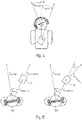
- Fig. 1 illustrates an embodiment of the apparatus 2, comprising a front-facing camera 4, for rendering an audio signal for a playback to a user wearing a headphone 6.
- the user's face is directed to the front-facing camera 4 and a reference numeral 4' indicates a field of vision of the front-facing camera 4.
- a depth camera e.g. using infrared projection in combination with infrared depth sensors to extract the depth map
- the apparatus 2 is a non-mobile device, i.e. a stationary device.
- the front-facing camera 4 (e.g. an optical sensor) is used to track the position (and/or orientation) of the user's face, the positional information (and/or orientation information) is (optionally) transformed to be from the perspective of the user rather than the camera, and finally this positional data is applied during the spatial audio processing.
- the apparatus 2 further comprises an orientation sensor, for example, a gyroscope which assists in tracking the orientation of the user's face. That is, even if the stationary device does not change the position, a front-facing surface of the stationary device, e.g., display may be rotatable.
- an orientation of the stationary device may be also changeable and therefore, in case the display of the stationary device is rotatable, at least one orientation sensor is required to accurately determine information about an orientation of a head of user in relation to the position (orientation) of the device.
- the entire environment is defined by the relationship between the device (apparatus) and the user's head, with the active processing happening when the user is within the field of vision of the camera 4'.
- Fig. 2 shows a schematic diagram of the stationary apparatus (device) as well as the mobile apparatus (device) 10 comprising an optical sensor 12, e.g. a camera, an orientation sensor 14, e.g. a gyroscope, a head orientation information generator 16 and a spatial (binaural) rendering core 18.
- the orientation sensor 14 is arranged in a predetermined positional relationship with respect to the optical sensor 12.
- the device depicted in Fig. 2 is the stationary device and also the mobile device.
- the device of Fig. 2 may further or optionally include a display, a speaker, an antenna, a data transmitter, a microphone, etc.
- a stationary device e.g. desktop monitor
- the video scene the device/apparatus
- the audio scene should also remain fixed, achieved by applying the head rotation data, obtained from headphone-mounted sensors or stationary cameras, and compensating for the movement. This adds a new degree of realism because the audio scene reacts as the user is accustomed to in real life.
- the present application also conveniently accounts for movement of both the user and their device in free space, which is to be expected with mobile devices.
- additional sensors for example, one or more orientation sensors
- the device e.g. built-in accelerometer or gyroscope or built-in cameras or any combination thereof
- additional sensor e.g. one or more orientation sensors within the device is required.
- Embodiments of this later case allow for large improvements in audio quality and overall user experiences by facilitating true spatial audio and do so robustly in a range of mobile environments.
- the use of the apparatus according to the present application is not limited to video use cases, but it would also bring improved audio quality to audio-only applications, such as voice calls or 3D audio playback, where the locally captured video is used for head tracking but can be discarded as soon as the head tracking data has been extracted.
- Fig. 3 schematically illustrates an example implementation of immersive conferencing, showing the local user via their front-facing camera and a 2D overhead representation of a conference call with four remote participants. Lines on the user face indicate an azimuthal position of user head.
- the mobile device it is used the front-facing camera and/or depth sensor, along with device's additional sensors (e.g. built-in accelerometer and/or gyroscope) to gain knowledge of both the device's position (and/or orientation) and the position (and/or orientation) of the user's head within the real world (for example, with respect to an Earth-fixed coordinate system or with respect to a direction of gravity).
- additional sensors e.g. built-in accelerometer and/or gyroscope
- AR augmented reality
- a possible (but typically minor) disadvantage with this method is that the user must be (or should be) facing the front-facing sensor and within its field of vision in order for the head tracking data to be available. For applications such as face-to-face video calling or video consumption this is almost certainly the case anyway.
- options (which may optionally be implemented) include remaining at the most recent state or it would also be trivial for the application to fall back to a default state (return head rotation values to default forward position, for example).
- Yet another option (which may optionally be implemented) is to use motion data from other sensors, e.g.
- the device preferably comprises one or more of optical sensors, e.g. one or more of cameras and one or more of orientation sensors, e.g. one or more of gyroscopes.
- the device according to the present application i.e. the front-facing spatial processing also delivers one key advantage over using head tracking data from sensors built into headphones.
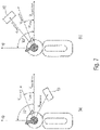
- the front-facing spatial processing also delivers one key advantage over using head tracking data from sensors built into headphones. For example, consider the scenario where a user makes a video call with spatial audio while walking along the street, as shown in Fig. 4 , with their device held out at arm's length (see Fig 4 (t1)), as is a common way of using video calls while on the go.
- the audio scene (one mono sound source in the example) would remain constant for the user, since the relationship between the position of the user's head and the position of the phone has not changed.
- the vector, originating from the user's head and passing though the camera of the device, will be referred to as the 'acoustic front' hereinafter in this description (wherein, optionally, the vertical spacing between the head and the camera may be left out of consideration).
- This (for example, the direction of the acoustic front, which may be represented by a vector) is the direction in space, where e.g. the center speaker of a 5.1 audio signal (5.1 surround sound) would be rendered to.
- the orientation and/or positional information is captured at a single point of reference - at the device (also designated as "apparatus”). It is also provided a robust user experience where other motion should be ignored, such as when the user is a passenger in a moving vehicle. It is compatible with any headset and easily implemented on modern devices featuring augmented reality (AR) support.
- AR augmented reality
- the orientation of the device (or apparatus) 10 may not always align with the up-axis (for example, a vertical direction, opposite to the direction of gravity), especially when the user is walking.
- the application should ensure that the AR framework compensates for the device roll angle, so it does not get used to render the audio signal. Only the head roll angle shall be used to configure the spatial renderer (which may, for example, perform the spatial rendering). Otherwise the audio scene would be rotated even though the user did not roll the head.
- the acoustic front is defined, for example shown in Fig. 5 , as the vector between the user's head and the camera of the device 10 (wherein, optionally, the vertical spacing between the head and the camera may be left out of consideration, such that, for example, the acoustic front is a horizontal vector or direction).
- Fig. 5 (a) depicts the scenario where the orientation of the device aligns with the acoustic front vector. In this case, the angle between vector "head front" and vector "device orientation” are identical to the correct yaw angle. But once the device orientation changes, as shown in Fig. 6 (b) , using this angle would cause an erroneous yaw value in the head rotation data used for the spatial rendering.
- a deviation, the angle ⁇ err , between the direction from the head of the user to the apparatus and a direction of an optical axis of the optical sensor is compensate or correct, for example, by using a processing of an image information obtained from the optical sensor. Accordingly, the device may, for example, determine ⁇ err , and consequently determine a correct yaw angle.
- Fig. 7 depicts two side views of the user with the device and the pitch angle of the head rotation data. Opposed to the yaw angle in Fig. 6 , for determining the pitch angle neither the device's position, nor its rotation is used (or reflected in a final result). That is, in case the position or the orientation of the device is changed, the vector of the acoustic front is not changed.
- the acoustic front is, for example, always a vector at a 90 degree angle to the up-axis (for example, may lie in a horizontal plane) and the pitch angle, for example, always refers to the angle between the vector head front and the acoustic front.
- the device may determine the pitch angle on the basis of these considerations or restrictions.
- Fig. 8 shows a flowchart for an example of a method rendering an audio signal for a playback to a user implemented by the apparatus shown in Fig. 2 according to the embodiments of the present application.
- the method comprises a step determining information about an orientation of a head of the user using an optical sensor (S10). That is, the information about the orientation of the head of the user is determined by using an optical sensor 12, e.g. using a camera or using a user-facing moving image capture device, and/or using a depth sensor and/or using a visual face/head tracking sensor, for example, using camera-captured data for head tracking.
- an optical sensor 12 e.g. using a camera or using a user-facing moving image capture device, and/or using a depth sensor and/or using a visual face/head tracking sensor, for example, using camera-captured data for head tracking.
- a step determining information about an orientation of the optical sensor 12 using an orientation sensor 14 is executed (S12). That is, for example, the information about an orientation of the optical sensor 12 is determined by using a gyroscope and/or a magnetic field sensor and/or a gravity sensor and/or an accelerometer and/or an optical sensor, etc., which is arranged in a predetermined positional relationship, e.g. mechanical relationship, with respect to the optical sensor 12, for example, to enable the apparatus to be aware of its position and/or orientation in a "real world" or in an Earth-fixed coordinate system.
- a gyroscope and/or a magnetic field sensor and/or a gravity sensor and/or an accelerometer and/or an optical sensor, etc. which is arranged in a predetermined positional relationship, e.g. mechanical relationship, with respect to the optical sensor 12, for example, to enable the apparatus to be aware of its position and/or orientation in a "real world" or in an Earth-fixed coordinate system.
- a step considering the information about the orientation of the optical sensor 12 when determining the information about the orientation of the head of the user is executed (S14). That is, for example, to obtain at least one parameter about the orientation of the head of the user with respect to an Earth-fixed coordinate system, substantially independent from a current orientation of the optical sensor 12 or from the orientation of the apparatus 10 carrying or comprising the optical sensor 12.
- a step performing a spatial rendering of an audio signal is executed (S16). That is, for example, for playback to the user via a speaker system or via a headset which is in communication with the apparatus 10, in dependence on the information about the orientation of the head of the user, for example, to adapt a virtual audio environment in dependence on the information about the orientation of the head of the user.
- the proposed solution combines existing technologies with a newly defined acoustic front that makes an ideal virtual environment for mobile communication and media consumption, and provides improvements over current state of the art through being:
- Embodiments create an Adaptive Acoustic Front for Immersive Audio Applications using a Mobile Device's Front-Facing Camera.
- Embodiments according to the present invention create a method to achieve the benefits of spatial audio processing using a novel combination of existing technologies.
- This method involves a typical consumer environment of a user wearing headphones and a device with a front-facing camera.
- the front-facing camera is used to track the position of the user's face, the positional information is transformed to be from the perspective of the user rather than the camera, and finally this positional data is applied during the spatial audio processing.
- the result is that the audio can use 3D spatial processing to complement the visual scene, with head tracking to improve the overall effect.
- the entire environment is defined by the relationship between the device and the user's head, with the active processing happening when the user is within the field of vision of the camera.
- This method can e.g. be applied to improve the immersion of communication and media consumption applications.
- the position and the orientation of the head of the user is determined by using sensors within the apparatus only.
- the head position is determined without any information from the device that may be mounted on the head, e.g., a head mounted display, a headphone or an earphone, attached to the user. Therefore, it is not necessary to transmit any data regarding the head position between the user device and the apparatus to determine the head position, and hence, it is possible to accurately determine the head position, since there is no transmission error regarding the head position data.
- the sensors are located only in the apparatus, i.e., it is not necessary to include any sensors to detect the head position within the user device. Therefore, it is possible to reduce a weight of the user device (e.g., sensors, batteries to supply power to sensors etc.) and to improve wearing comfort of the user. This also means that the present application is immediately compatible with existing headphones.
- aspects have been described in the context of an apparatus, it is clear that these aspects also represent a description of the corresponding method, where a block or device corresponds to a method step or a feature of a method step. Analogously, aspects described in the context of a method step also represent a description of a corresponding block or item or feature of a corresponding apparatus.
- Some or all of the method steps may be executed by (or using) a hardware apparatus, like for example, a microprocessor, a programmable computer or an electronic circuit. In some embodiments, one or more of the most important method steps may be executed by such an apparatus.
- the inventive data stream can be stored on a digital storage medium or can be transmitted on a transmission medium such as a wireless transmission medium or a wired transmission medium such as the Internet.
- embodiments of the application can be implemented in hardware or in software.
- the implementation can be performed using a digital storage medium, for example a floppy disk, a DVD, a Blu-Ray, a CD, a ROM, a PROM, an EPROM, an EEPROM or a FLASH memory, having electronically readable control signals stored thereon, which cooperate (or are capable of cooperating) with a programmable computer system such that the respective method is performed. Therefore, the digital storage medium may be computer readable.
- Some embodiments according to the invention comprise a data carrier having electronically readable control signals, which are capable of cooperating with a programmable computer system, such that one of the methods described herein is performed.
- embodiments of the present application can be implemented as a computer program product with a program code, the program code being operative for performing one of the methods when the computer program product runs on a computer.
- the program code may, for example, be stored on a machine readable carrier.
- inventions comprise a computer program for performing one of the methods described herein, stored on a machine readable carrier.
- an embodiment of the inventive method is, therefore, a computer program having a program code for performing one of the methods described herein, when the computer program runs on a computer.
- a further embodiment of the inventive methods is, therefore, a data carrier (or a digital storage medium, or a computer-readable medium) comprising, recorded thereon, the computer program for performing one of the methods described herein.
- the data carrier, the digital storage medium or the recorded medium are typically tangible and/or non-transitionary.
- a further embodiment of the inventive method is, therefore, a data stream or a sequence of signals representing the computer program for performing one of the methods described herein.
- the data stream or the sequence of signals may, for example, be configured to be transferred via a data communication connection, for example via the internet.
- a further embodiment comprises a processing means, for example a computer, or a programmable logic device, configured to or adapted to perform one of the methods described herein.
- a processing means for example a computer, or a programmable logic device, configured to or adapted to perform one of the methods described herein.
- a further embodiment comprises a computer having installed thereon the computer program for performing one of the methods described herein.
- a further embodiment according to the invention comprises an apparatus or a system configured to transfer (for example, electronically or optically) a computer program for performing one of the methods described herein to a receiver.
- the receiver may, for example, be a computer, a mobile device, a memory device or the like.
- the apparatus or system may, for example, comprise a file server for transferring the computer program to the receiver.
- a programmable logic device for example a field programmable gate array
- a field programmable gate array may cooperate with a microprocessor in order to perform one of the methods described herein.
- the methods are preferably performed by any hardware apparatus.
- the apparatus described herein may be implemented using a hardware apparatus, or using a computer, or using a combination of a hardware apparatus and a computer.
- the apparatus described herein, or any components of the apparatus described herein, may be implemented at least partially in hardware and/or in software.
Landscapes
- Engineering & Computer Science (AREA)
- Physics & Mathematics (AREA)
- Theoretical Computer Science (AREA)
- General Physics & Mathematics (AREA)
- General Engineering & Computer Science (AREA)
- Multimedia (AREA)
- Acoustics & Sound (AREA)
- Signal Processing (AREA)
- Human Computer Interaction (AREA)
- Health & Medical Sciences (AREA)
- Audiology, Speech & Language Pathology (AREA)
- General Health & Medical Sciences (AREA)
- Stereophonic System (AREA)
- User Interface Of Digital Computer (AREA)
- Measurement Of The Respiration, Hearing Ability, Form, And Blood Characteristics Of Living Organisms (AREA)
Claims (24)
- Eine Vorrichtung (10) zum Aufbereiten eines Audiosignals für eine Wiedergabe einem Nutzer gegenüber,wobei die Vorrichtung (10) dazu ausgebildet ist, Informationen über eine Orientierung eines Kopfes des Nutzers unter Verwendung eines optischen Sensors (12) zu bestimmen;wobei die Vorrichtung (10) dazu ausgebildet ist, Informationen über eine Orientierung des optischen Sensors (12) in einem erdfesten Koordinatensystem unter Verwendung eines Orientierungssensors (14) zu bestimmen, der in einer vorbestimmten Positionsbeziehung hinsichtlich des optischen Sensors (12) angeordnet ist;wobei die Vorrichtung (10) dazu ausgebildet ist, die Informationen über die Orientierung des optischen Sensors (12) beim Bestimmen der Informationen über die Orientierung des Kopfes zu berücksichtigen, um zumindest einen Parameter über die Orientierung des Kopfes hinsichtlich des erdfesten Koordinatensystems im Wesentlichen unabhängig von einer aktuellen Orientierung des optischen Sensors (12) oder von einer Orientierung der Vorrichtung (10) zu erhalten, wenn sie den optischen Sensor (12) trägt oder aufweist;wobei die Vorrichtung (10) dazu ausgebildet ist, eine räumliche Aufbereitung eines Audiosignals in Abhängigkeit von den Informationen über die Orientierung des Kopfes des Nutzers durchzuführen.
- Die Vorrichtung (10) gemäß Anspruch 1,
wobei die Vorrichtung (10) dazu ausgebildet ist, eine binaurale Aufbereitung in Abhängigkeit von den Informationen über die Orientierung des Kopfes des Nutzers durchzuführen. - Die Vorrichtung (10) gemäß einem der Ansprüche 1 bis 2,
wobei die Vorrichtung (10) den optischen Sensor (12) aufweist, wobei der optische Sensor (12) dazu angeordnet ist, einen Kopf des Nutzers nachzuverfolgen. - Die Vorrichtung (10) gemäß einem der Ansprüche 1 bis 3,wobei die Vorrichtung (10) dazu ausgebildet ist, Gierungswinkelinformationen zu bestimmen, die einen Winkel zwischen einer Kopfvorwärtsrichtung des Kopfes des Nutzers und einer Position der Vorrichtung (10) beschreiben; und/oderwobei die Vorrichtung (10) dazu ausgebildet ist, Querneigungswinkelinformationen zu bestimmen, die einen Querneigungswinkel des Kopfes des Nutzers beschreiben; und/oderwobei die Vorrichtung (10) dazu ausgebildet ist, Längsneigungswinkelinformationen zu bestimmen, die einen Längsneigungswinkel des Kopfes des Nutzers beschreiben.
- Die Vorrichtung (10) gemäß einem der Ansprüche 1 bis 4,
wobei die Vorrichtung (10) dazu ausgebildet ist, Gierungswinkelinformationen zu bestimmen, die einen Gierungswinkel zwischen einer Kopfvorwärtsrichtung des Kopfes des Nutzers und einer Position der Vorrichtung (10) beschreiben, derart, dass die Gierungswinkelinformationen einen Azimutwinkel zwischen der Kopfvorwärtsrichtung des Kopfes des Nutzers und einer Richtung von dem Kopf des Nutzers zu der Vorrichtung (10) beschreiben. - Die Vorrichtung (10) gemäß Anspruch 5,
wobei die Vorrichtung (10) dazu ausgebildet ist, eine Abweichung zwischen der Richtung von dem Kopf des Nutzers zu der Vorrichtung und einer Richtung einer optischen Achse des optischen Sensors zumindest teilweise zu kompensieren. - Die Vorrichtung (10) gemäß einem der Ansprüche 1 bis 6,
wobei die Vorrichtung (10) dazu ausgebildet ist, Querneigungswinkelinformationen zu bestimmen, die einen Querneigungswinkel des Kopfes des Nutzers bezüglich einer vertikalen Richtung oder bezüglich einer Kopfvorwärtsrichtung beschreiben. - Die Vorrichtung (10) gemäß Anspruch 7,
wobei die Vorrichtung (10) dazu ausgebildet ist, einen Querneigungswinkel der Vorrichtung (10) oder des optischen Sensors auf der Basis der Informationen über die Orientierung des optischen Sensors (12) beim Bestimmen der Querneigungswinkelinformationen, die den Querneigungswinkel des Kopfes des Nutzers beschreiben, zumindest teilweise zu kompensieren. - Die Vorrichtung (10) gemäß einem der Ansprüche 1 bis 8,
wobei die Vorrichtung (10) dazu ausgebildet ist, Längsneigungswinkelinformationen zu bestimmen, die einen Längsneigungswinkel des Kopfes des Nutzers bezüglich einer horizontalen Ausrichtung beschreiben. - Die Vorrichtung (10) gemäß Anspruch 9,
wobei die Vorrichtung (10) dazu ausgebildet ist, die Orientierung der Vorrichtung (10) oder des optischen Sensors auf der Basis der Informationen über die Orientierung des optischen Sensors (12) beim Bestimmen der Längsneigungswinkelinformationen des Kopfes des Nutzers zumindest teilweise zu kompensieren. - Die Vorrichtung (10) gemäß einem der Ansprüche 1 bis 10,
wobei die Vorrichtung (10) dazu ausgebildet ist, die Informationen über die Orientierung des Kopfes auf der Basis von Informationen von Sensoren, die in der Vorrichtung (10) angeordnet oder mechanisch an der Vorrichtung (10) befestigt sind, zu bestimmen. - Die Vorrichtung (10) gemäß einem der Ansprüche 1 bis 11,wobei die Vorrichtung (10) dazu ausgebildet ist, die Informationen über die Orientierung des Kopfes auf der Basis von Informationen von Sensoren, die in der Vorrichtung (10) angeordnet oder mechanisch an der Vorrichtung (10) befestigt sind,und auf der Basis eines oder mehrerer zusätzlicher Sensoren, die sich außerhalb der Vorrichtung (10) befinden, zu bestimmen.
- Die Vorrichtung (10) gemäß Anspruch 12,
wobei die Vorrichtung (10) dazu ausgebildet ist, Informationen von den externen Sensoren nur zu berücksichtigen, falls sich herausstellt, dass die Informationen über die Orientierung des Kopfes nicht zuverlässig auf der Basis der Informationen von dem optischen Sensor (12) gewonnen werden können. - Die Vorrichtung (10) gemäß einem der Ansprüche 1 bis 13,wobei die Vorrichtung (10) dazu ausgebildet ist, eine akustische Vorwärtsrichtung zu bestimmen, die eine Projektion einer Richtung von dem Kopf zu der Vorrichtung (10) in eine horizontale Ebene hinein ist, undwobei die Vorrichtung (10) dazu ausgebildet ist, die räumliche Aufbereitung des Audiosignals in Abhängigkeit von der akustischen Vorwärtsrichtung durchzuführen.
- Die Vorrichtung (10) gemäß einem der Ansprüche 1 bis 13,wobei die Vorrichtung (10) dazu ausgebildet ist, eine akustische Vorwärtsrichtung zu bestimmen, die eine Richtung von dem Kopf zu der Vorrichtung (10) ist, undwobei die Vorrichtung (10) dazu ausgebildet ist, die räumliche Aufbereitung des Audiosignals in Abhängigkeit von der akustischen Vorwärtsrichtung durchzuführen.
- Die Vorrichtung (10) gemäß Anspruch 14 oder 15,
wobei die Vorrichtung (10) dazu ausgebildet ist, eine Mitte einer Audioszene so aufzubereiten, dass sie in der akustischen Vorwärtsrichtung ist. - Die Vorrichtung (10) gemäß einem der Ansprüche 14 bis 16,
wobei die Vorrichtung (10) dazu ausgebildet ist, die Längsneigungswinkelinformationen, die einen Längsneigungswinkel bezüglich der akustischen Vorwärtsrichtung beschreiben, zu bestimmen. - Die Vorrichtung (10) gemäß einem der Ansprüche 1 bis 17,
wobei die Vorrichtung (10) dazu ausgebildet ist, eine Mittelachse einer virtuellen Audioumgebung auf gleicher Höhe mit dem Kopf eines Nutzers zu halten. - Die Vorrichtung (10) gemäß einem der Ansprüche 1 bis 18,
wobei die Vorrichtung (10) dazu ausgebildet ist, einen Höhenunterschied zwischen dem Kopf des Nutzers und der Vorrichtung (10) beim Bestimmen der Informationen über eine Orientierung des Kopfes unberücksichtigt zu lassen. - Die Vorrichtung (10) gemäß einem der Ansprüche 1 bis 19,
wobei die Vorrichtung (10) tragbar ist und/oder wobei die Vorrichtung (10) ein Mobilkommunikationsgerät ist. - Die Vorrichtung (10) gemäß einem der Ansprüche 1 bis 20,wobei die Vorrichtung (10) dazu ausgebildet ist, eine räumliche Aufbereitung mehrerer Audiosignale durchzuführen, die Audiobeiträge von einer Mehrzahl von Teilnehmern einer Audiokonferenz oder einer Audio/Video-Konferenz darstellen, und/oderwobei die Vorrichtung (10) dazu ausgebildet ist, eine räumliche Aufbereitung einer Rundsendung oder eines Inhalts auf lokalen Speichermedien oder eines gestreamten Audioinhalts durchzuführen.
- Die Vorrichtung (10) gemäß einem der Ansprüche 1 bis 21,wobei die Vorrichtung (10) dazu ausgebildet ist, Informationen darüber zu erhalten, an welcher Azimutposition und bei welcher Höhe oder Erhöhung ein Audioinhalt aufbereitet werden sollte, undwobei die Vorrichtung (10) dazu ausgebildet ist, Informationen über eine Azimutposition der Vorrichtung (10) aus der Perspektive des Nutzers unter Verwendung von Informationen von dem optischen Sensor und der Informationen über die Orientierung des optischen Sensors (12) zu bestimmen; undwobei die Vorrichtung (10) dazu ausgebildet ist, einen Parameter über die Orientierung des Kopfes bezüglich eines erdfesten Koordinatensystems unter Verwendung der Informationen von dem optischen Sensor (12) und der Informationen über die Orientierung des optischen Sensors (12) zu bestimmen; undwobei die Vorrichtung (10) dazu ausgebildet ist, den Audioinhalt unter Verwendung der Informationen über die Azimutposition und des Parameters über die Orientierung des Kopfes bezüglich des erdfesten Koordinatensystems aufzubereiten.
- Ein Verfahren zum Aufbereiten eines Audiosignals für eine Wiedergabe einem Nutzer gegenüber,wobei das Verfahren ein Bestimmen von Informationen über eine Orientierung eines Kopfes des Nutzers unter Verwendung eines optischen Sensors (12) aufweist;wobei das Verfahren ein Bestimmen von Informationen über eine Orientierung des optischen Sensors (12) in einem erdfesten Koordinatensystem unter Verwendung eines Orientierungssensors (14), der in einer vorbestimmten Positionsbeziehung hinsichtlich des optischen Sensors (12) angeordnet ist, aufweist;wobei das Verfahren ein Berücksichtigen der Informationen über die Orientierung des optischen Sensors (12) beim Bestimmen der Informationen über die Orientierung des Kopfes, um zumindest einen Parameter über die Orientierung des Kopfes hinsichtlich des erdfesten Koordinatensystems im Wesentlichen unabhängig von einer aktuellen Orientierung des optischen Sensors (12) oder von einer Orientierung der Vorrichtung (10) zu erhalten, wenn sie den optischen Sensor (12) trägt oder aufweist, aufweist;wobei das Verfahren ein Durchführen einer räumlichen Aufbereitung eines Audiosignals in Abhängigkeit von den Informationen über die Orientierung des Kopfes des Nutzers aufweist.
- Ein Computerprogramm zum Durchführen des Verfahrens gemäß Anspruch 23, wenn das Computerprogramm auf einem Computer abläuft.
Applications Claiming Priority (2)
| Application Number | Priority Date | Filing Date | Title |
|---|---|---|---|
| EP18169137 | 2018-04-24 | ||
| PCT/EP2019/060207 WO2019206827A1 (en) | 2018-04-24 | 2019-04-18 | Apparatus and method for rendering an audio signal for a playback to a user |
Publications (2)
| Publication Number | Publication Date |
|---|---|
| EP3785452A1 EP3785452A1 (de) | 2021-03-03 |
| EP3785452B1 true EP3785452B1 (de) | 2022-05-11 |
Family
ID=62110863
Family Applications (1)
| Application Number | Title | Priority Date | Filing Date |
|---|---|---|---|
| EP19717951.8A Active EP3785452B1 (de) | 2018-04-24 | 2019-04-18 | Vorrichtung und verfahren zur wiedergabe eines audiosignals zur wiedergabe an einen benutzer |
Country Status (7)
| Country | Link |
|---|---|
| US (1) | US11343634B2 (de) |
| EP (1) | EP3785452B1 (de) |
| JP (1) | JP7157985B2 (de) |
| CN (1) | CN112335264B (de) |
| BR (1) | BR112020021608A2 (de) |
| RU (1) | RU2759012C1 (de) |
| WO (1) | WO2019206827A1 (de) |
Families Citing this family (16)
| Publication number | Priority date | Publication date | Assignee | Title |
|---|---|---|---|---|
| US11304021B2 (en) * | 2018-11-29 | 2022-04-12 | Sony Interactive Entertainment Inc. | Deferred audio rendering |
| EP4124072B1 (de) * | 2020-03-19 | 2026-01-07 | Panasonic Intellectual Property Corporation of America | Tonwiedergabeverfahren, computerprogramm und tonwiedergabevorrichtung |
| US12069469B2 (en) | 2020-06-20 | 2024-08-20 | Apple Inc. | Head dimension estimation for spatial audio applications |
| US12474365B2 (en) | 2020-06-20 | 2025-11-18 | Apple Inc. | User posture transition detection and classification |
| US12108237B2 (en) | 2020-06-20 | 2024-10-01 | Apple Inc. | Head tracking correlated motion detection for spatial audio applications |
| KR20220025458A (ko) * | 2020-08-24 | 2022-03-03 | 주식회사 아모센스 | 전자 장치 및 전자 장치의 작동 방법 |
| US12219344B2 (en) * | 2020-09-25 | 2025-02-04 | Apple Inc. | Adaptive audio centering for head tracking in spatial audio applications |
| US11750745B2 (en) | 2020-11-18 | 2023-09-05 | Kelly Properties, Llc | Processing and distribution of audio signals in a multi-party conferencing environment |
| GB2601805A (en) * | 2020-12-11 | 2022-06-15 | Nokia Technologies Oy | Apparatus, Methods and Computer Programs for Providing Spatial Audio |
| US20220225050A1 (en) * | 2021-01-13 | 2022-07-14 | Dolby Laboratories Licensing Corporation | Head tracked spatial audio and/or video rendering |
| US20250159425A1 (en) * | 2022-03-15 | 2025-05-15 | Sony Group Corporation | Information processing device, information processing method, and recording medium |
| JP2025529877A (ja) * | 2022-08-24 | 2025-09-09 | ドルビー ラボラトリーズ ライセンシング コーポレイション | 複数のデバイスによってキャプチャされた音声のレンダリング |
| CN116017265B (zh) * | 2023-01-03 | 2026-04-10 | 湖北星纪魅族科技有限公司 | 音频处理方法、电子设备、可穿戴设备、车辆及存储介质 |
| US12389188B2 (en) | 2023-01-30 | 2025-08-12 | Microsoft Technology Licensing, Llc | Motion tracking calibration for wearable device |
| US12326968B1 (en) * | 2024-05-02 | 2025-06-10 | Dell Products L.P. | Orienting digital humans towards isolated speaker |
| WO2026039556A1 (en) * | 2024-08-16 | 2026-02-19 | Qualcomm Incorporated | Method and system of multi-modal tracking for dynamic spatial audio rendering |
Family Cites Families (20)
| Publication number | Priority date | Publication date | Assignee | Title |
|---|---|---|---|---|
| US20090219224A1 (en) * | 2008-02-28 | 2009-09-03 | Johannes Elg | Head tracking for enhanced 3d experience using face detection |
| CN101350931B (zh) | 2008-08-27 | 2011-09-14 | 华为终端有限公司 | 音频信号的生成、播放方法及装置、处理系统 |
| US9037468B2 (en) * | 2008-10-27 | 2015-05-19 | Sony Computer Entertainment Inc. | Sound localization for user in motion |
| TR201908933T4 (tr) | 2009-02-13 | 2019-07-22 | Koninklijke Philips Nv | Mobil uygulamalar için baş hareketi izleme. |
| US8970478B2 (en) | 2009-10-14 | 2015-03-03 | Nokia Corporation | Autostereoscopic rendering and display apparatus |
| US9332372B2 (en) * | 2010-06-07 | 2016-05-03 | International Business Machines Corporation | Virtual spatial sound scape |
| US9142062B2 (en) * | 2011-03-29 | 2015-09-22 | Qualcomm Incorporated | Selective hand occlusion over virtual projections onto physical surfaces using skeletal tracking |
| US9293138B2 (en) | 2013-05-14 | 2016-03-22 | Amazon Technologies, Inc. | Storing state information from network-based user devices |
| CN103491397B (zh) * | 2013-09-25 | 2017-04-26 | 歌尔股份有限公司 | 一种实现自适应环绕声的方法和系统 |
| EP4421617A3 (de) * | 2013-10-31 | 2024-11-06 | Dolby Laboratories Licensing Corporation | Binaurales rendering für kopfhörer mit metadatenverarbeitung |
| DE102014009298B4 (de) * | 2014-06-26 | 2025-05-22 | Audi Ag | Verfahren zum Betreiben eines Virtual-Reality-Systems und Virtual-Reality-System |
| US20150382130A1 (en) * | 2014-06-27 | 2015-12-31 | Patrick Connor | Camera based adjustments to 3d soundscapes |
| US9854371B2 (en) * | 2014-10-22 | 2017-12-26 | Small Signals, Llc | Information processing system, apparatus and method for measuring a head-related transfer function |
| US9787846B2 (en) * | 2015-01-21 | 2017-10-10 | Microsoft Technology Licensing, Llc | Spatial audio signal processing for objects with associated audio content |
| EP3452891B1 (de) | 2016-05-02 | 2024-04-10 | Waves Audio Ltd. | Kopfverfolgung mit adaptiver referenz |
| US10803642B2 (en) * | 2017-08-18 | 2020-10-13 | Adobe Inc. | Collaborative virtual reality anti-nausea and video streaming techniques |
| WO2019046706A1 (en) * | 2017-09-01 | 2019-03-07 | Dts, Inc. | IDEAL POINT ADAPTATION FOR VIRTUALIZED AUDIO |
| EP3486749B1 (de) * | 2017-11-20 | 2022-05-11 | Nokia Technologies Oy | Bereitstellung von inhalt von virtueller realität |
| EP3729829B1 (de) * | 2017-12-19 | 2024-09-18 | Koninklijke KPN N.V. | Verbesserte audiovisuelle mehrbenutzerkommunikation |
| WO2019170874A1 (en) * | 2018-03-08 | 2019-09-12 | Sony Corporation | Electronic device, method and computer program |
-
2019
- 2019-04-18 EP EP19717951.8A patent/EP3785452B1/de active Active
- 2019-04-18 BR BR112020021608-9A patent/BR112020021608A2/pt unknown
- 2019-04-18 CN CN201980040475.4A patent/CN112335264B/zh active Active
- 2019-04-18 WO PCT/EP2019/060207 patent/WO2019206827A1/en not_active Ceased
- 2019-04-18 JP JP2020559554A patent/JP7157985B2/ja active Active
- 2019-04-18 RU RU2020138215A patent/RU2759012C1/ru active
-
2020
- 2020-10-22 US US17/077,740 patent/US11343634B2/en active Active
Also Published As
| Publication number | Publication date |
|---|---|
| JP2021522720A (ja) | 2021-08-30 |
| US11343634B2 (en) | 2022-05-24 |
| US20210044913A1 (en) | 2021-02-11 |
| WO2019206827A1 (en) | 2019-10-31 |
| JP7157985B2 (ja) | 2022-10-21 |
| BR112020021608A2 (pt) | 2021-01-26 |
| CN112335264A (zh) | 2021-02-05 |
| EP3785452A1 (de) | 2021-03-03 |
| CN112335264B (zh) | 2022-09-06 |
| RU2759012C1 (ru) | 2021-11-08 |
Similar Documents
| Publication | Publication Date | Title |
|---|---|---|
| EP3785452B1 (de) | Vorrichtung und verfahren zur wiedergabe eines audiosignals zur wiedergabe an einen benutzer | |
| EP3729829B1 (de) | Verbesserte audiovisuelle mehrbenutzerkommunikation | |
| KR102197544B1 (ko) | 공간화 오디오를 가진 혼합 현실 시스템 | |
| US10681276B2 (en) | Virtual reality video processing to compensate for movement of a camera during capture | |
| US11052547B2 (en) | Robot and housing | |
| US10808879B2 (en) | Actuator apparatus | |
| JP6580516B2 (ja) | 処理装置および画像決定方法 | |
| CN120298631A (zh) | 视听呈现装置及其操作方法 | |
| CN113906736A (zh) | 视频分发系统、视频分发方法和显示终端 | |
| JP2017216643A (ja) | アクチュエータ装置 | |
| US20260032307A1 (en) | Delay optimization for multiple audio streams | |
| JP7047085B2 (ja) | 画像生成装置、画像生成方法、およびプログラム | |
| CN110677781A (zh) | 利用编码光线引导扬声器阵列和麦克风阵列的系统和方法 | |
| WO2021049356A1 (ja) | 再生装置、再生方法、及び記録媒体 | |
| CN114651282A (zh) | 信息处理设备、信息处理方法和程序 | |
| JP6615716B2 (ja) | ロボットおよび筐体 | |
| WO2017183292A1 (ja) | 処理装置および画像決定方法 | |
| WO2017183293A1 (ja) | 位相差増幅装置 | |
| KR20240088517A (ko) | 공간 음향 처리 방법 및 이를 위한 장치 |
Legal Events
| Date | Code | Title | Description |
|---|---|---|---|
| STAA | Information on the status of an ep patent application or granted ep patent |
Free format text: STATUS: UNKNOWN |
|
| STAA | Information on the status of an ep patent application or granted ep patent |
Free format text: STATUS: THE INTERNATIONAL PUBLICATION HAS BEEN MADE |
|
| PUAI | Public reference made under article 153(3) epc to a published international application that has entered the european phase |
Free format text: ORIGINAL CODE: 0009012 |
|
| STAA | Information on the status of an ep patent application or granted ep patent |
Free format text: STATUS: REQUEST FOR EXAMINATION WAS MADE |
|
| 17P | Request for examination filed |
Effective date: 20201124 |
|
| AK | Designated contracting states |
Kind code of ref document: A1 Designated state(s): AL AT BE BG CH CY CZ DE DK EE ES FI FR GB GR HR HU IE IS IT LI LT LU LV MC MK MT NL NO PL PT RO RS SE SI SK SM TR |
|
| AX | Request for extension of the european patent |
Extension state: BA ME |
|
| DAV | Request for validation of the european patent (deleted) | ||
| DAX | Request for extension of the european patent (deleted) | ||
| GRAP | Despatch of communication of intention to grant a patent |
Free format text: ORIGINAL CODE: EPIDOSNIGR1 |
|
| STAA | Information on the status of an ep patent application or granted ep patent |
Free format text: STATUS: GRANT OF PATENT IS INTENDED |
|
| RIC1 | Information provided on ipc code assigned before grant |
Ipc: G06F 3/16 20060101ALI20211116BHEP Ipc: G06F 3/01 20060101ALI20211116BHEP Ipc: H04S 7/00 20060101AFI20211116BHEP |
|
| INTG | Intention to grant announced |
Effective date: 20211203 |
|
| GRAS | Grant fee paid |
Free format text: ORIGINAL CODE: EPIDOSNIGR3 |
|
| GRAA | (expected) grant |
Free format text: ORIGINAL CODE: 0009210 |
|
| STAA | Information on the status of an ep patent application or granted ep patent |
Free format text: STATUS: THE PATENT HAS BEEN GRANTED |
|
| RAP3 | Party data changed (applicant data changed or rights of an application transferred) |
Owner name: FRAUNHOFER-GESELLSCHAFT ZUR FOERDERUNG DER ANGEWANDTEN FORSCHUNG E.V. |
|
| AK | Designated contracting states |
Kind code of ref document: B1 Designated state(s): AL AT BE BG CH CY CZ DE DK EE ES FI FR GB GR HR HU IE IS IT LI LT LU LV MC MK MT NL NO PL PT RO RS SE SI SK SM TR |
|
| REG | Reference to a national code |
Ref country code: GB Ref legal event code: FG4D |
|
| REG | Reference to a national code |
Ref country code: CH Ref legal event code: EP |
|
| REG | Reference to a national code |
Ref country code: AT Ref legal event code: REF Ref document number: 1492520 Country of ref document: AT Kind code of ref document: T Effective date: 20220515 |
|
| REG | Reference to a national code |
Ref country code: DE Ref legal event code: R096 Ref document number: 602019014874 Country of ref document: DE |
|
| REG | Reference to a national code |
Ref country code: IE Ref legal event code: FG4D |
|
| REG | Reference to a national code |
Ref country code: LT Ref legal event code: MG9D |
|
| REG | Reference to a national code |
Ref country code: NL Ref legal event code: MP Effective date: 20220511 |
|
| REG | Reference to a national code |
Ref country code: AT Ref legal event code: MK05 Ref document number: 1492520 Country of ref document: AT Kind code of ref document: T Effective date: 20220511 |
|
| PG25 | Lapsed in a contracting state [announced via postgrant information from national office to epo] |
Ref country code: SE Free format text: LAPSE BECAUSE OF FAILURE TO SUBMIT A TRANSLATION OF THE DESCRIPTION OR TO PAY THE FEE WITHIN THE PRESCRIBED TIME-LIMIT Effective date: 20220511 Ref country code: PT Free format text: LAPSE BECAUSE OF FAILURE TO SUBMIT A TRANSLATION OF THE DESCRIPTION OR TO PAY THE FEE WITHIN THE PRESCRIBED TIME-LIMIT Effective date: 20220912 Ref country code: NO Free format text: LAPSE BECAUSE OF FAILURE TO SUBMIT A TRANSLATION OF THE DESCRIPTION OR TO PAY THE FEE WITHIN THE PRESCRIBED TIME-LIMIT Effective date: 20220811 Ref country code: NL Free format text: LAPSE BECAUSE OF FAILURE TO SUBMIT A TRANSLATION OF THE DESCRIPTION OR TO PAY THE FEE WITHIN THE PRESCRIBED TIME-LIMIT Effective date: 20220511 Ref country code: LT Free format text: LAPSE BECAUSE OF FAILURE TO SUBMIT A TRANSLATION OF THE DESCRIPTION OR TO PAY THE FEE WITHIN THE PRESCRIBED TIME-LIMIT Effective date: 20220511 Ref country code: HR Free format text: LAPSE BECAUSE OF FAILURE TO SUBMIT A TRANSLATION OF THE DESCRIPTION OR TO PAY THE FEE WITHIN THE PRESCRIBED TIME-LIMIT Effective date: 20220511 Ref country code: GR Free format text: LAPSE BECAUSE OF FAILURE TO SUBMIT A TRANSLATION OF THE DESCRIPTION OR TO PAY THE FEE WITHIN THE PRESCRIBED TIME-LIMIT Effective date: 20220812 Ref country code: FI Free format text: LAPSE BECAUSE OF FAILURE TO SUBMIT A TRANSLATION OF THE DESCRIPTION OR TO PAY THE FEE WITHIN THE PRESCRIBED TIME-LIMIT Effective date: 20220511 Ref country code: BG Free format text: LAPSE BECAUSE OF FAILURE TO SUBMIT A TRANSLATION OF THE DESCRIPTION OR TO PAY THE FEE WITHIN THE PRESCRIBED TIME-LIMIT Effective date: 20220811 Ref country code: AT Free format text: LAPSE BECAUSE OF FAILURE TO SUBMIT A TRANSLATION OF THE DESCRIPTION OR TO PAY THE FEE WITHIN THE PRESCRIBED TIME-LIMIT Effective date: 20220511 |
|
| PG25 | Lapsed in a contracting state [announced via postgrant information from national office to epo] |
Ref country code: RS Free format text: LAPSE BECAUSE OF FAILURE TO SUBMIT A TRANSLATION OF THE DESCRIPTION OR TO PAY THE FEE WITHIN THE PRESCRIBED TIME-LIMIT Effective date: 20220511 Ref country code: PL Free format text: LAPSE BECAUSE OF FAILURE TO SUBMIT A TRANSLATION OF THE DESCRIPTION OR TO PAY THE FEE WITHIN THE PRESCRIBED TIME-LIMIT Effective date: 20220511 Ref country code: LV Free format text: LAPSE BECAUSE OF FAILURE TO SUBMIT A TRANSLATION OF THE DESCRIPTION OR TO PAY THE FEE WITHIN THE PRESCRIBED TIME-LIMIT Effective date: 20220511 Ref country code: IS Free format text: LAPSE BECAUSE OF FAILURE TO SUBMIT A TRANSLATION OF THE DESCRIPTION OR TO PAY THE FEE WITHIN THE PRESCRIBED TIME-LIMIT Effective date: 20220911 |
|
| PG25 | Lapsed in a contracting state [announced via postgrant information from national office to epo] |
Ref country code: SM Free format text: LAPSE BECAUSE OF FAILURE TO SUBMIT A TRANSLATION OF THE DESCRIPTION OR TO PAY THE FEE WITHIN THE PRESCRIBED TIME-LIMIT Effective date: 20220511 Ref country code: SK Free format text: LAPSE BECAUSE OF FAILURE TO SUBMIT A TRANSLATION OF THE DESCRIPTION OR TO PAY THE FEE WITHIN THE PRESCRIBED TIME-LIMIT Effective date: 20220511 Ref country code: RO Free format text: LAPSE BECAUSE OF FAILURE TO SUBMIT A TRANSLATION OF THE DESCRIPTION OR TO PAY THE FEE WITHIN THE PRESCRIBED TIME-LIMIT Effective date: 20220511 Ref country code: ES Free format text: LAPSE BECAUSE OF FAILURE TO SUBMIT A TRANSLATION OF THE DESCRIPTION OR TO PAY THE FEE WITHIN THE PRESCRIBED TIME-LIMIT Effective date: 20220511 Ref country code: EE Free format text: LAPSE BECAUSE OF FAILURE TO SUBMIT A TRANSLATION OF THE DESCRIPTION OR TO PAY THE FEE WITHIN THE PRESCRIBED TIME-LIMIT Effective date: 20220511 Ref country code: DK Free format text: LAPSE BECAUSE OF FAILURE TO SUBMIT A TRANSLATION OF THE DESCRIPTION OR TO PAY THE FEE WITHIN THE PRESCRIBED TIME-LIMIT Effective date: 20220511 Ref country code: CZ Free format text: LAPSE BECAUSE OF FAILURE TO SUBMIT A TRANSLATION OF THE DESCRIPTION OR TO PAY THE FEE WITHIN THE PRESCRIBED TIME-LIMIT Effective date: 20220511 |
|
| REG | Reference to a national code |
Ref country code: DE Ref legal event code: R097 Ref document number: 602019014874 Country of ref document: DE |
|
| PLBE | No opposition filed within time limit |
Free format text: ORIGINAL CODE: 0009261 |
|
| STAA | Information on the status of an ep patent application or granted ep patent |
Free format text: STATUS: NO OPPOSITION FILED WITHIN TIME LIMIT |
|
| PG25 | Lapsed in a contracting state [announced via postgrant information from national office to epo] |
Ref country code: AL Free format text: LAPSE BECAUSE OF FAILURE TO SUBMIT A TRANSLATION OF THE DESCRIPTION OR TO PAY THE FEE WITHIN THE PRESCRIBED TIME-LIMIT Effective date: 20220511 |
|
| 26N | No opposition filed |
Effective date: 20230214 |
|
| PG25 | Lapsed in a contracting state [announced via postgrant information from national office to epo] |
Ref country code: SI Free format text: LAPSE BECAUSE OF FAILURE TO SUBMIT A TRANSLATION OF THE DESCRIPTION OR TO PAY THE FEE WITHIN THE PRESCRIBED TIME-LIMIT Effective date: 20220511 |
|
| P01 | Opt-out of the competence of the unified patent court (upc) registered |
Effective date: 20230517 |
|
| REG | Reference to a national code |
Ref country code: CH Ref legal event code: PL |
|
| PG25 | Lapsed in a contracting state [announced via postgrant information from national office to epo] |
Ref country code: LU Free format text: LAPSE BECAUSE OF NON-PAYMENT OF DUE FEES Effective date: 20230418 |
|
| REG | Reference to a national code |
Ref country code: BE Ref legal event code: MM Effective date: 20230430 |
|
| PG25 | Lapsed in a contracting state [announced via postgrant information from national office to epo] |
Ref country code: MC Free format text: LAPSE BECAUSE OF FAILURE TO SUBMIT A TRANSLATION OF THE DESCRIPTION OR TO PAY THE FEE WITHIN THE PRESCRIBED TIME-LIMIT Effective date: 20220511 |
|
| PG25 | Lapsed in a contracting state [announced via postgrant information from national office to epo] |
Ref country code: MC Free format text: LAPSE BECAUSE OF FAILURE TO SUBMIT A TRANSLATION OF THE DESCRIPTION OR TO PAY THE FEE WITHIN THE PRESCRIBED TIME-LIMIT Effective date: 20220511 Ref country code: LI Free format text: LAPSE BECAUSE OF NON-PAYMENT OF DUE FEES Effective date: 20230430 Ref country code: IT Free format text: LAPSE BECAUSE OF FAILURE TO SUBMIT A TRANSLATION OF THE DESCRIPTION OR TO PAY THE FEE WITHIN THE PRESCRIBED TIME-LIMIT Effective date: 20220511 Ref country code: CH Free format text: LAPSE BECAUSE OF NON-PAYMENT OF DUE FEES Effective date: 20230430 |
|
| REG | Reference to a national code |
Ref country code: IE Ref legal event code: MM4A |
|
| PG25 | Lapsed in a contracting state [announced via postgrant information from national office to epo] |
Ref country code: BE Free format text: LAPSE BECAUSE OF NON-PAYMENT OF DUE FEES Effective date: 20230430 |
|
| PG25 | Lapsed in a contracting state [announced via postgrant information from national office to epo] |
Ref country code: IE Free format text: LAPSE BECAUSE OF NON-PAYMENT OF DUE FEES Effective date: 20230418 |
|
| PG25 | Lapsed in a contracting state [announced via postgrant information from national office to epo] |
Ref country code: IE Free format text: LAPSE BECAUSE OF NON-PAYMENT OF DUE FEES Effective date: 20230418 |
|
| PG25 | Lapsed in a contracting state [announced via postgrant information from national office to epo] |
Ref country code: BG Free format text: LAPSE BECAUSE OF FAILURE TO SUBMIT A TRANSLATION OF THE DESCRIPTION OR TO PAY THE FEE WITHIN THE PRESCRIBED TIME-LIMIT Effective date: 20220511 |
|
| PG25 | Lapsed in a contracting state [announced via postgrant information from national office to epo] |
Ref country code: BG Free format text: LAPSE BECAUSE OF FAILURE TO SUBMIT A TRANSLATION OF THE DESCRIPTION OR TO PAY THE FEE WITHIN THE PRESCRIBED TIME-LIMIT Effective date: 20220511 |
|
| PGFP | Annual fee paid to national office [announced via postgrant information from national office to epo] |
Ref country code: DE Payment date: 20250417 Year of fee payment: 7 |
|
| PGFP | Annual fee paid to national office [announced via postgrant information from national office to epo] |
Ref country code: FR Payment date: 20250422 Year of fee payment: 7 |
|
| PG25 | Lapsed in a contracting state [announced via postgrant information from national office to epo] |
Ref country code: CY Free format text: LAPSE BECAUSE OF FAILURE TO SUBMIT A TRANSLATION OF THE DESCRIPTION OR TO PAY THE FEE WITHIN THE PRESCRIBED TIME-LIMIT; INVALID AB INITIO Effective date: 20190418 |
|
| PG25 | Lapsed in a contracting state [announced via postgrant information from national office to epo] |
Ref country code: HU Free format text: LAPSE BECAUSE OF FAILURE TO SUBMIT A TRANSLATION OF THE DESCRIPTION OR TO PAY THE FEE WITHIN THE PRESCRIBED TIME-LIMIT; INVALID AB INITIO Effective date: 20190418 |
|
| PG25 | Lapsed in a contracting state [announced via postgrant information from national office to epo] |
Ref country code: TR Free format text: LAPSE BECAUSE OF FAILURE TO SUBMIT A TRANSLATION OF THE DESCRIPTION OR TO PAY THE FEE WITHIN THE PRESCRIBED TIME-LIMIT Effective date: 20220511 |
|
| PGFP | Annual fee paid to national office [announced via postgrant information from national office to epo] |
Ref country code: GB Payment date: 20260324 Year of fee payment: 8 |