EP3785609B1 - Fehlerschätzung lokaler aktivierungszeiten (lat), die durch einen mehrfachelektrodenkatheter gemessen werden - Google Patents
Fehlerschätzung lokaler aktivierungszeiten (lat), die durch einen mehrfachelektrodenkatheter gemessen werden Download PDFInfo
- Publication number
- EP3785609B1 EP3785609B1 EP20191576.6A EP20191576A EP3785609B1 EP 3785609 B1 EP3785609 B1 EP 3785609B1 EP 20191576 A EP20191576 A EP 20191576A EP 3785609 B1 EP3785609 B1 EP 3785609B1
- Authority
- EP
- European Patent Office
- Prior art keywords
- annotation
- signal
- doa
- processor
- corrected
- Prior art date
- Legal status (The legal status is an assumption and is not a legal conclusion. Google has not performed a legal analysis and makes no representation as to the accuracy of the status listed.)
- Active
Links
Images








Classifications
-
- A—HUMAN NECESSITIES
- A61—MEDICAL OR VETERINARY SCIENCE; HYGIENE
- A61B—DIAGNOSIS; SURGERY; IDENTIFICATION
- A61B5/00—Measuring for diagnostic purposes; Identification of persons
- A61B5/24—Detecting, measuring or recording bioelectric or biomagnetic signals of the body or parts thereof
- A61B5/25—Bioelectric electrodes therefor
- A61B5/279—Bioelectric electrodes therefor specially adapted for particular uses
- A61B5/28—Bioelectric electrodes therefor specially adapted for particular uses for electrocardiography [ECG]
- A61B5/283—Invasive
- A61B5/287—Holders for multiple electrodes, e.g. electrode catheters for electrophysiological study [EPS]
-
- A—HUMAN NECESSITIES
- A61—MEDICAL OR VETERINARY SCIENCE; HYGIENE
- A61B—DIAGNOSIS; SURGERY; IDENTIFICATION
- A61B5/00—Measuring for diagnostic purposes; Identification of persons
- A61B5/24—Detecting, measuring or recording bioelectric or biomagnetic signals of the body or parts thereof
- A61B5/316—Modalities, i.e. specific diagnostic methods
- A61B5/318—Heart-related electrical modalities, e.g. electrocardiography [ECG]
- A61B5/339—Displays specially adapted therefor
- A61B5/341—Vectorcardiography [VCG]
-
- A—HUMAN NECESSITIES
- A61—MEDICAL OR VETERINARY SCIENCE; HYGIENE
- A61B—DIAGNOSIS; SURGERY; IDENTIFICATION
- A61B18/00—Surgical instruments, devices or methods for transferring non-mechanical forms of energy to or from the body
-
- A—HUMAN NECESSITIES
- A61—MEDICAL OR VETERINARY SCIENCE; HYGIENE
- A61B—DIAGNOSIS; SURGERY; IDENTIFICATION
- A61B18/00—Surgical instruments, devices or methods for transferring non-mechanical forms of energy to or from the body
- A61B18/04—Surgical instruments, devices or methods for transferring non-mechanical forms of energy to or from the body by heating
- A61B18/12—Surgical instruments, devices or methods for transferring non-mechanical forms of energy to or from the body by heating by passing a current through the tissue to be heated, e.g. high-frequency current
- A61B18/14—Probes or electrodes therefor
- A61B18/1492—Probes or electrodes therefor having a flexible, catheter-like structure, e.g. for heart ablation
-
- A—HUMAN NECESSITIES
- A61—MEDICAL OR VETERINARY SCIENCE; HYGIENE
- A61B—DIAGNOSIS; SURGERY; IDENTIFICATION
- A61B5/00—Measuring for diagnostic purposes; Identification of persons
- A61B5/24—Detecting, measuring or recording bioelectric or biomagnetic signals of the body or parts thereof
- A61B5/316—Modalities, i.e. specific diagnostic methods
- A61B5/318—Heart-related electrical modalities, e.g. electrocardiography [ECG]
- A61B5/346—Analysis of electrocardiograms
- A61B5/349—Detecting specific parameters of the electrocardiograph cycle
- A61B5/363—Detecting tachycardia or bradycardia
-
- A—HUMAN NECESSITIES
- A61—MEDICAL OR VETERINARY SCIENCE; HYGIENE
- A61B—DIAGNOSIS; SURGERY; IDENTIFICATION
- A61B5/00—Measuring for diagnostic purposes; Identification of persons
- A61B5/68—Arrangements of detecting, measuring or recording means, e.g. sensors, in relation to patient
- A61B5/6846—Arrangements of detecting, measuring or recording means, e.g. sensors, in relation to patient specially adapted to be brought in contact with an internal body part, i.e. invasive
- A61B5/6847—Arrangements of detecting, measuring or recording means, e.g. sensors, in relation to patient specially adapted to be brought in contact with an internal body part, i.e. invasive mounted on an invasive device
- A61B5/6852—Catheters
-
- A—HUMAN NECESSITIES
- A61—MEDICAL OR VETERINARY SCIENCE; HYGIENE
- A61B—DIAGNOSIS; SURGERY; IDENTIFICATION
- A61B5/00—Measuring for diagnostic purposes; Identification of persons
- A61B5/68—Arrangements of detecting, measuring or recording means, e.g. sensors, in relation to patient
- A61B5/6846—Arrangements of detecting, measuring or recording means, e.g. sensors, in relation to patient specially adapted to be brought in contact with an internal body part, i.e. invasive
- A61B5/6847—Arrangements of detecting, measuring or recording means, e.g. sensors, in relation to patient specially adapted to be brought in contact with an internal body part, i.e. invasive mounted on an invasive device
- A61B5/6852—Catheters
- A61B5/6859—Catheters with multiple distal splines
-
- A—HUMAN NECESSITIES
- A61—MEDICAL OR VETERINARY SCIENCE; HYGIENE
- A61B—DIAGNOSIS; SURGERY; IDENTIFICATION
- A61B5/00—Measuring for diagnostic purposes; Identification of persons
- A61B5/68—Arrangements of detecting, measuring or recording means, e.g. sensors, in relation to patient
- A61B5/6846—Arrangements of detecting, measuring or recording means, e.g. sensors, in relation to patient specially adapted to be brought in contact with an internal body part, i.e. invasive
- A61B5/6867—Arrangements of detecting, measuring or recording means, e.g. sensors, in relation to patient specially adapted to be brought in contact with an internal body part, i.e. invasive specially adapted to be attached or implanted in a specific body part
- A61B5/6869—Heart
-
- A—HUMAN NECESSITIES
- A61—MEDICAL OR VETERINARY SCIENCE; HYGIENE
- A61B—DIAGNOSIS; SURGERY; IDENTIFICATION
- A61B5/00—Measuring for diagnostic purposes; Identification of persons
- A61B5/72—Signal processing specially adapted for physiological signals or for diagnostic purposes
- A61B5/7225—Details of analogue processing, e.g. isolation amplifier, gain or sensitivity adjustment, filtering, baseline or drift compensation
-
- A—HUMAN NECESSITIES
- A61—MEDICAL OR VETERINARY SCIENCE; HYGIENE
- A61B—DIAGNOSIS; SURGERY; IDENTIFICATION
- A61B5/00—Measuring for diagnostic purposes; Identification of persons
- A61B5/72—Signal processing specially adapted for physiological signals or for diagnostic purposes
- A61B5/7235—Details of waveform analysis
- A61B5/725—Details of waveform analysis using specific filters therefor, e.g. Kalman or adaptive filters
-
- A—HUMAN NECESSITIES
- A61—MEDICAL OR VETERINARY SCIENCE; HYGIENE
- A61B—DIAGNOSIS; SURGERY; IDENTIFICATION
- A61B5/00—Measuring for diagnostic purposes; Identification of persons
- A61B5/72—Signal processing specially adapted for physiological signals or for diagnostic purposes
- A61B5/7271—Specific aspects of physiological measurement analysis
- A61B5/7275—Determining trends in physiological measurement data; Predicting development of a medical condition based on physiological measurements, e.g. determining a risk factor
-
- A—HUMAN NECESSITIES
- A61—MEDICAL OR VETERINARY SCIENCE; HYGIENE
- A61B—DIAGNOSIS; SURGERY; IDENTIFICATION
- A61B5/00—Measuring for diagnostic purposes; Identification of persons
- A61B5/74—Details of notification to user or communication with user or patient; User input means
- A61B5/742—Details of notification to user or communication with user or patient; User input means using visual displays
- A61B5/7435—Displaying user selection data, e.g. icons in a graphical user interface
-
- G—PHYSICS
- G01—MEASURING; TESTING
- G01F—MEASURING VOLUME, VOLUME FLOW, MASS FLOW OR LIQUID LEVEL; METERING BY VOLUME
- G01F17/00—Methods or apparatus for determining the capacity of containers or cavities, or the volume of solid bodies
-
- G—PHYSICS
- G06—COMPUTING OR CALCULATING; COUNTING
- G06F—ELECTRIC DIGITAL DATA PROCESSING
- G06F17/00—Digital computing or data processing equipment or methods, specially adapted for specific functions
- G06F17/10—Complex mathematical operations
- G06F17/18—Complex mathematical operations for evaluating statistical data, e.g. average values, frequency distributions, probability functions, regression analysis
-
- A—HUMAN NECESSITIES
- A61—MEDICAL OR VETERINARY SCIENCE; HYGIENE
- A61B—DIAGNOSIS; SURGERY; IDENTIFICATION
- A61B18/00—Surgical instruments, devices or methods for transferring non-mechanical forms of energy to or from the body
- A61B2018/00315—Surgical instruments, devices or methods for transferring non-mechanical forms of energy to or from the body for treatment of particular body parts
- A61B2018/00345—Vascular system
- A61B2018/00351—Heart
-
- A—HUMAN NECESSITIES
- A61—MEDICAL OR VETERINARY SCIENCE; HYGIENE
- A61B—DIAGNOSIS; SURGERY; IDENTIFICATION
- A61B18/00—Surgical instruments, devices or methods for transferring non-mechanical forms of energy to or from the body
- A61B2018/00571—Surgical instruments, devices or methods for transferring non-mechanical forms of energy to or from the body for achieving a particular surgical effect
- A61B2018/00577—Ablation
-
- A—HUMAN NECESSITIES
- A61—MEDICAL OR VETERINARY SCIENCE; HYGIENE
- A61B—DIAGNOSIS; SURGERY; IDENTIFICATION
- A61B18/00—Surgical instruments, devices or methods for transferring non-mechanical forms of energy to or from the body
- A61B2018/00636—Sensing and controlling the application of energy
- A61B2018/00773—Sensed parameters
- A61B2018/00839—Bioelectrical parameters, e.g. ECG, EEG
-
- A—HUMAN NECESSITIES
- A61—MEDICAL OR VETERINARY SCIENCE; HYGIENE
- A61B—DIAGNOSIS; SURGERY; IDENTIFICATION
- A61B18/00—Surgical instruments, devices or methods for transferring non-mechanical forms of energy to or from the body
- A61B18/04—Surgical instruments, devices or methods for transferring non-mechanical forms of energy to or from the body by heating
- A61B18/12—Surgical instruments, devices or methods for transferring non-mechanical forms of energy to or from the body by heating by passing a current through the tissue to be heated, e.g. high-frequency current
- A61B18/14—Probes or electrodes therefor
- A61B2018/1405—Electrodes having a specific shape
-
- A—HUMAN NECESSITIES
- A61—MEDICAL OR VETERINARY SCIENCE; HYGIENE
- A61B—DIAGNOSIS; SURGERY; IDENTIFICATION
- A61B5/00—Measuring for diagnostic purposes; Identification of persons
- A61B5/74—Details of notification to user or communication with user or patient; User input means
- A61B5/742—Details of notification to user or communication with user or patient; User input means using visual displays
- A61B5/743—Displaying an image simultaneously with additional graphical information, e.g. symbols, charts, function plots
Definitions
- the present invention relates generally to electrophysiological mapping, and particularly to cardiac electrophysiological mapping.
- U.S. Patent Application Publication 2017/0042449 describes a system and method for local EP characterization of cardiac substrate using multi-electrode catheters.
- the system selects at least one clique of electrodes from a plurality of electrodes to derive at least one orientation independent signal from the at least one clique of electrodes from the information content corresponding to weighted parts of electrogram signals.
- the system displays or outputs catheter orientation independent electrophysiologic information to a user or a process.
- U.S. Patent Application Publication 2015/0366476 describes a system and method for mapping the electrical activity of the heart.
- the system may include a catheter shaft with a plurality of electrodes.
- a processor of the system may be capable of collecting a set of signals from at least one of the plurality of electrodes. The set of signals may be collected over a time period.
- the processor may also be capable of calculating at least one propagation vector from the set of signals, generating a data set from the at least one propagation vector, generating a statistical distribution of the data set and generating a visual representation of the statistical distribution, such as a circular histogram of angles.
- a direction (e.g. propagation angle) and velocity of cellular wavefront propagation may be determined by a comparing the activation times sensed by neighboring electrodes to the target electrode for which the propagation vector is being determined.
- U.S. Patent Application Publication 2017/0202470 describes a system and method of identifying focal sources.
- the method can comprise detecting, via sensors, electrocardiogram (ECG) signals over time, each ECG signal detected via one of the sensors having a location in a heart and indicating electrical activity of the heart, each signal comprising at least an R wave and an S wave; creating an R-S map comprising an R-to-S ratio for each of the ECG signals, the R-to-S ratio comprising a ratio of absolute magnitude of the R wave to absolute magnitude of the S wave; identifying, for each of the ECG signals, local activation times (LATs); and correlating the R-to-S ratios for the ECG signals on the R-S map and the identified LATs and using the correlation to identify the focal sources.
- ECG electrocardiogram
- U.S. Patent Application Publication 2017/0281031 describes electroanatomic mapping carried out by inserting a multi-electrode probe into a heart of a living subject, recording electrograms from the electrodes concurrently at respective locations in the heart, delimiting respective activation time intervals in the electrograms, generating a map of electrical propagation waves from the activation time intervals, maximizing coherence of the waves by adjusting local activation times within the activation time intervals of the electrograms, and reporting the adjusted local activation times.
- U.S. Patent Application Publication 2004/0243012 describes a method and system for identifying and localizing a reentrant circuit isthmus in a heart of a subject during sinus rhythm.
- the method may include (a) receiving electrogram signals from the heart during sinus rhythm via electrodes, (b) creating a map based on the electrogram signals, (c) determining, based on the map, a location of the reentrant circuit isthmus in the heart, and (d) displaying the location of the reentrant circuit isthmus.
- An Automated Algorithm for Determining Conduction Velocity, Wavefront Direction and Origin of Focal Cardiac Arrhythmias Using a Multipolar Catheter discusses a method for determining locations of focal arrhythmia sources and quantifying myocardial conduction velocities.
- US 2017/0281031 A1 discusses an electroanatomic mapping technique carried out by inserting a multielectrode probe into a heart of a living subject, recording electrograms from the electrodes concurrently at respective locations in the heart, delimiting respective activation time intervals in the electrograms, generating a map of electrical propagation waves from the activation time intervals, maximizing coherence of the waves by adjusting local activation times within the activation time intervals of the electrograms, and reporting the adjusted local activation times.
- an aberrant electrophysiological (EP) wave impulse is abnormally spread from an ectopic focus in the heart.
- a focal type of arrhythmia may occur due to localized abnormal cardiac tissue that triggers the aberrant EP wave, or by localized abnormal cardiac tissue that forms a small reentry path which causes an erroneous spread of an existing EP wave.
- a localized arrhythmogenic tissue may be ablated to eliminate a focal type of arrhythmia. Therefore, identifying a location of a focal type of arrhythmogenic tissue may be clinically valuable.
- Exemplary embodiments of the present invention that are described hereinafter provide EP mapping systems and methods for automatically identifying a location of focal arrhythmogenic activity in the heart. Additionally, or alternatively, some exemplary embodiments provide methods for estimating annotation errors in measured EP values and correcting the annotation errors according to their cause. In some exemplary embodiments, based on a set of annotations that include the corrected annotation, a processor generates an EP map of at least a portion of the heart (e.g., a LAT map).
- the EP mapping system uses a multielectrode catheter, such as the Pentaray ® catheter (made by Biosense-Webster, Irvine, California), to obtain multiple acquisitions from a cardiac region covered by the electrodes. Each acquisition comprises a set of EP signals measured by the electrodes, with the set sized according to the number of electrodes.
- a multielectrode catheter such as the Pentaray ® catheter (made by Biosense-Webster, Irvine, California)
- Pentaray ® catheter made by Biosense-Webster, Irvine, California
- Each acquisition comprises a set of EP signals measured by the electrodes, with the set sized according to the number of electrodes.
- other multi-electrode catheters may be used, mutatis mutandis, with the disclosed techniques.
- a processor then estimates, for each acquisition, a direction of arrival (DOA) and a distance, R DOA , relative to the electrodes, from which the acquired set of EP signals originated.
- DOA direction of arrival
- R DOA distance
- the processor aggregates the acquisitions to form a statistical distribution (e.g., a histogram, or a cluster map in X-Y space) of the acquisition as a function of estimated DOA and distance, and checks, using a statistical test, whether the statistical distribution of the acquisitions is consistent.
- Constancy is checked in accordance with a predefined consistency criterion.
- relevant consistency tests include, but are not limited to, constancy estimator or use of confidence interval.
- a cluster map in X-Y space may be consistent if one or more clusters in the map contain each at least a given percentage of the data points (e.g., 10%), as described below.
- the processor derives from the statistical distribution an estimated location in the heart of a focal source of an arrhythmogenic activity that generated the received EP signals. Finally, the processor overlays the estimated location of the focal source on an anatomical map of at least a portion of the heart.
- the processor in order to estimate DOA and distance, the processor annotates each EP signal with the time of arrival of an EP wavefront, named hereinafter also as original annotations.
- the processor extracts from the originally annotated set of signals (i.e., from a given acquisition) a respective set of relative times of arrival.
- the processor analyzes the extracted set of relative times to indicate the nature of the EP wave in question, as described below.
- the model assumes that each acquisition is uniquely related to a single travelling broad EP wavefront having a constant velocity over the region in which the EP signals are acquired.
- the processor when aggregating the acquisitions, pre-filters the acquisitions and includes in the statistical distribution of the acquisitions only the pre-filtered acquisitions.
- the processor pre-filters the acquisitions by applying the steps of: (a) using the estimated DOA and distance, calculating a modeled set of relative times of arrival, for each acquisition, that would have resulted from an EP wave originating at a focal source having the estimated DOA and distance relative to the catheter, and (b) for each acquisition, applying a test to determine to what degree the extracted set and modeled set of relative times of arrival are similar, and dropping any acquisition that yields dissimilar sets of timings. Examples of relevant tests include a geometrical similarity test, and comparison of estimation errors (also termed hereinafter timing errors) to a given threshold.
- the geometrical similarity test comprises applying a cosine-similarity geometrical test between the extracted and modeled sets of relative times of arrival.
- the degree of similarity may range between zero for full dissimilarity to one for full similarity.
- a least square method is used as the geometrical test.
- An aberrant EP wave may not necessarily be of focal origin nature, which may be indicated by the similarity check.
- the derived modeled relative times may be used to adjust time values of original annotations that are not well defined, i.e., where the voltage-time slope of a wavefront is shallower than a prespecified slope.
- the adjusted annotations are also referred hereinafter as corrected annotations.
- the processor is programmed in software containing a particular algorithm that enables the processor to conduct each of the processor related steps and functions outlined above.
- the disclosed technique for automatically identifying a focal source of an arrhythmogenic activity in the heart may improve the clinical outcome of a related catheter-based treatment of arrhythmia.
- Fig. 1 is a schematic, pictorial illustration of an electrophysiological (EP) mapping system 10, in accordance with an exemplary embodiment of the present invention.
- System 10 comprises a catheter 14, which is inserted by a physician 32 through the patient's vascular system into a chamber or vascular structure of a heart 12. Physician 32 brings the catheter's distal tip 18 into contact with the heart wall, for example, at an EP mapping target site.
- Catheter 14 typically comprises a handle 20 which has suitable controls to enable physician 32 to steer, position and orient the distal end of the catheter 14 as desired for the EP mapping.
- Catheter 14 is a multi-electrode catheter, such as the aforementioned Pentaray ® catheter shown in inset 37.
- the Pentaray catheter 14 comprises five flexible arms 15, with each arm carrying four electrodes 16.
- a total of twenty EP signals are obtained by system 10 at each instance of EP signal acquisition, as further described in Fig. 2 .
- Catheter 14 is coupled to console 24, which enables physician 32 to observe and regulate the functions of catheter 14.
- the distal portion of the catheter 14 may contain various sensors, such as contact force sensors (not shown) and a magnetic sensor 33 that provide position, direction, and orientation signals to a processor 22, located in the console 24.
- Processor 22 may fulfill several processing functions as described below.
- electrical signals can be conveyed to and from the heart 12 from electrodes 16 located at or near the distal tip 18 of catheter 14 via cable 31 to console 24.
- Pacing signals and other control signals may be conveyed from the console 24 through cable 31 and electrodes 16 to the heart 12.
- Console 24 includes a monitor 29 driven by processor 22.
- Signal processing circuits in an electrical interface 34 typically receive, amplify, filter, and digitize signals from the catheter 14, including signals generated by the above noted sensors and the plurality of sensing electrodes 16. The digitized signals are received and used by the console 24 and the positioning system to compute the position and orientation of the catheter 14 and to analyze the EP signals from electrodes 16 as described in further detail below.
- the respective locations of electrodes 16 are tracked.
- the tracking may be performed, for example, using the CARTO ® 3 system, produced by Biosense-Webster.
- Such a system measures impedances between electrodes 16 and a plurality of external electrodes 30 that are coupled to the body of the patient.
- three external electrodes 30 may be coupled to the patient's chest, and another three external electrodes may be coupled to the patient's back. (For ease of illustration, only chest electrodes are shown in Fig. 1 .).
- Wire connections 35 link the console 24 with body surface electrodes 30 and other components of a positioning sub-system to measure location and orientation coordinates of catheter 14.
- ACL Active Current Location
- system 10 comprises, in addition to, or instead of, the ACL tracking subsystem, a magnetic position tracking subsystem that determines the position and orientation of magnetic sensor 33, at a distal end of catheter 14, by generating magnetic fields in a predefined working volume and sensing these fields at the catheter, using field generating coils 28.
- a magnetic position tracking subsystem that determines the position and orientation of magnetic sensor 33, at a distal end of catheter 14, by generating magnetic fields in a predefined working volume and sensing these fields at the catheter, using field generating coils 28.
- electrical activation maps may be prepared, according to the methods disclosed in U.S. Patents 6,226,542 , and 6,301,496 , and 6,892,091 , which are assigned to the assignee of the present patent application.
- Processor 22 uses software stored in a memory 25 to operate system 10.
- the software may be downloaded to processor 22 in electronic form, over a network, for example, or it may, alternatively or additionally, be provided and/or stored on non-transitory tangible media, such as magnetic, optical, or electronic memory.
- processor 22 runs a dedicated algorithm as disclosed herein, including in Fig. 2 , that enables processor 22 to perform the disclosed steps, as further described below.
- Fig. 1 The exemplary illustration shown in Fig. 1 is chosen purely for the sake of conceptual clarity. Other types of sensing geometries, such as of a basket catheter or the Lasso ® Catheter (produced by Biosense-Webster) may also be employed.
- Fig. 2 is a flow chart that schematically illustrates a method for automatic identification of a location of a focal source of arrhythmia, in accordance with an exemplary embodiment of the present invention.
- the algorithm carries out a process that begins with physician 32 inserting catheter 14 having a plurality of sensing electrode 16 into heart 12 of a patient, at a catheter insertion step 100.
- system 10 receives a collection of acquisitions of sets of EP signals from electrodes 16 that were brought in contact with cardiac tissue by physician 32, at an EP signals acquisition step 102.
- the system collects between 100 and 200 acquisitions comprising ECG segments having each a typical duration of 100-200mSec.
- an automatic segmentation of the 30 second window is performed by processor 22, so as to produce segments of 100-200mSec, each segment corresponds to a single activation propagating through the atria.
- processor 22 derives from each acquisition estimated values of DOA and distance of a presumed focal source, at a DOA derivation step 104.
- Processor 22 then prefilters each acquisition to drop acquisitions not suitable for inclusion in subsequent statistical analysis, at a prefiltration step 106.
- processor 22 prefilters the acquisition by comparing errors in estimated relative times between extracted EP values and modeled EP values. This stage may include attempting further processing, such as including iterative calculation to improve DOA estimation and thereby reduce estimation errors, as described below.
- the processor prefilters the acquisition by running a geometrical test of the consistency of modeled EP values and the extracted EP values (e.g., running cosine-similarity test).
- processor 22 aggregates the verified DOA and distance values.
- processor 22 runs a statistical test to find one or more candidates of DOA and distance (i.e., candidate focal locations), if such exist, at a statistical analysis step 110.
- the processor verifies if and which of the candidate locations is a valid location, by projecting the location on the anatomy, at a projection validation step 112.
- the processor verifies for validated candidate location that at least a minimal number of focal indicative ECG signals, described below, were acquired at the validated location, at a direct validation step 114.
- processor 22 overlays the one or more identified locations of a focal source of arrhythmogenic activation an anatomical map of at least a portion of heart 12.
- FIG. 2 The example flow chart shown in Fig. 2 is chosen purely for the sake of conceptual clarity. More details and specific exemplary embodiments of the steps described briefly above are brought below, including in flowcharts of Figs. 5 and 6 .
- Figs. 3A and 3B are two plots showing graphs 42 of EP signals that were acquired by the system of Fig. 1 , in accordance with an exemplary embodiment of the present invention.
- the shown EP signals were acquired, for example, by the EP mapping system of Fig. 1 using catheter 14.
- the two acquisition are part of multiple acquisitions, numbered between several tens and several hundred. Such a collection may include acquisitions taken at different intra-cardiac placements of the catheter and/or repeated acquisitions taken during the same placement.
- each of the plurality of electrodes has a location in the heart.
- the graphs show originally annotated times 44 at which the EP wave "strikes" each of the twenty electrodes of catheter 14.
- the annotations are made by a method known in the art, such as described in U.S. Patent 8,700,136 , which is assigned to the assignee of the present patent application.
- Figs. 3A and 3B some of the voltage-time slopes of the EP signal that are originally annotated are not well defined, i.e., are shallow (for example, in graphs 10 and 11 of Fig. 3B ).
- the disclosed technique improves the accuracy of such annotations, by deriving corrected annotations, as shown below in Figs. 7A , 8A and 9A , even if a focal source of arrhythmogenic activity is not identified by the technique.
- modeled times that are derived below, which are based on the known geometry of catheter 14, are used to adjust time values of original annotations that are not well defined, i.e., where the voltage-time slope seen in Figs. 3A and 3B is shallower than a prespecified slope.
- Figs. 3A and 3B are brought by way of example. If another catheter having multiple electrodes is used, such as basket or Lasso catheters, the size of acquisition (e.g., number of graphs in a set) and the annotated times will reflect the geometry of the given catheter, while similarly used by the disclosed technique.
- the size of acquisition e.g., number of graphs in a set
- the annotated times will reflect the geometry of the given catheter, while similarly used by the disclosed technique.
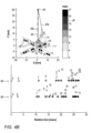
- Figs. 4A and 4B are plots showing relative arrival times extracted and modeled using EP signals of graphs of Figs. 3A and 3B , respectively, in accordance with an exemplary embodiment of the present invention.
- Processor 22 will pre-filter the acquisitions according to respective extracted set of relative times of arrival by performing the steps described below.
- Extracted times 66 in Figs. 4A and 4B are derived by processor 22 calculating time differences between original annotated times 44 of Figs. 3A and 3B , respectively.
- Respective modeled relative times 68 in Figs. 4A and 4B are subsequently derived by processor 22, using corrected annotated times (not shown, as described below.
- a color scale 48 in the upper part of Figs. 4A and 4B encodes the relative times of arrival by color encoding each of the depicted twenty electrodes 16 of catheter 14.
- the upper part of Figs. 4A and 4B further shows the tracked positions of electrodes 16 (over schematically demarked arms 15 of Pentaray catheter 14) at the two instances where the electrodes acquired the EP signals.
- the position of each electrode 16 in 3D space is tracked using, for example, the aforementioned ACL tracking technique.
- the X-Y-Z axis (Z not shown) belong to a fixed reference axial system, such as of position tracking system 20 applying the ACL method.
- processor 22 Based on extracted relative times of arrival 66, processor 22 estimates geometrically (e.g., as indicated by arrows 40a and 40b) a presumed focal source 50 from which the EP wave appears to come, as further marked by a distance indicated by line 60 that connects the common location at which arrows 40a and 40b originate from distal tip 18 of catheter 14.
- Figs. 4A and 4B shows on the same graph set of extracted relative times of arrival 66, and the respective modeled set relative times of arrival 68.
- Relative times of arrival 66 are derived by processor 22 from the originally annotated times at which the actual EP wave "strikes" the electrodes.
- Modeled times 68 are calculated by processor 22 using estimated DOA 55 and distance 60, assuming a simulated EP wave originating at a focal source 50 having the estimated DOA and distance relative to electrodes 16.
- an acquisition is determined indicative of a focal source by the processor only if a cosine-similarity timings match derived from the acquisition exceeds a value of 0.9.
- Geometrical test e.g., metrics
- cosine-similarity that check to what degree the extracted and modeled sets are similar, such as the Hamming-distance, may be used.
- Cosine-similarity in which a normalized inner product of the two ordered sets is calculated, may give any value between -1 and 1. Practically, the cosine-similarity is particularly used in positive space, where the outcome is bound within [0,1). For example, a value of 1 corresponds to full similarity, whereas a value of zero, or any negative value, indicates full dissimilarity. In an exemplary embodiment, if the calculated cosine-similarity gives a value above a prespecified minimum value, such as above 0.9, the processor determines the sets to be similar.
- Processor 22 runs the similarity check over all the sets derived from the collection of acquisitions, and drops acquisitions having cosine-similarity below the prespecified minimum value (e.g., ⁇ 0.9).
- DOA phase r 50 ⁇ r 18
- r 50 and r 18 are the vector coordinates of the presumed focal source 50 and of catheter's 14 distal tip 18, respectively.
- r 18 when converting the system coordinates from 3D to 2D, r 18 will be zero vector, since the center of the catheter is placed at the origin of the XY space.
- Fig. 5 is a flow chart that schematically illustrates a method for deriving direction of arrival (DOA) and distance along the steps illustrated in Figs. 4A and 4B , in accordance with an exemplary embodiment of the present invention.
- the process begins with processor 22 extracting relative times of arrival 66 from the originally annotated EP signals, at a relative times extraction step 200.
- processor 22 derives per acquisition estimated values of DOA 55 and distance 60 of the EP wave, at a DOA and distance estimation step 202.
- processor 22 calculates relative times that a focal wave having the tentative DOA and distance from step 106 would have generated, at a relative times modeling step 204.
- Processor 22 then checks, for example by using a cosine-similarity test, to what degree the extracted and modeled sets of relative times are similar, at a similarity checking step 206.
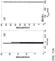
- processor 22 stores or drops the bad DOA and distance values as being non-indicative, at an acquisition dropping step 208. All acquisitions having sets of extracted and modeled relative times that are found similar (i.e., passed prefiltration) are aggregated by processor 22 into separate distributions as a function of DOA and distance (e.g., into histograms 70 and 72 of Figs. 11A and 11B below), at an aggregation step 210. As shown below in Figs. 11A and 11B , the aggregated DOA and distance are statistically analyzed to find a location of a focal source, if one deemed from the histograms to exist.
- Fig. 5 The exemplary flow chart shown in Fig. 5 is chosen purely for the sake of conceptual clarity. Additional steps may be typically performed, such as physician 32 initially anatomically mapping relevant parts of heart 12 (e.g., using fast anatomical mapping (FAM) procedure) to obtain an anatomical map.
- FAM fast anatomical mapping
- the criteria may vary with the type of statistical tools used.
- dropped sets of modeled timings may still be used for adjusting respective originally annotated times that are not well defined, as described below under "LAT improvements.”
- Fig. 6 is a flow chart that schematically illustrates a method for deriving direction of arrival (DOA) from a focal source, in accordance with another exemplary embodiment of the present invention.
- DOE direction of arrival
- the process shown in Fig. 6 begins with processor 22 extracting relative times of arrival 66 from the originally annotated EP signals, at a relative times extraction step 300.
- the algorithm checks whether to apply a 3D or 2D weighted DOA model estimation, by checking whether projecting (i.e., projection step 302) the catheter into a 2D space is valid, as described below, at a projection checking step 304.
- processor 22 runs a 3D weighted DOA finding model, at a 3D modeling step 306, or a 2D weighted DOA finding model, at a 2D modeling step 308, respectively.
- processor 22 than checks if estimated errors between modeled and extracted relative times are lower than a given threshold, at an estimation error step 310.
- processor 22 applies a LAT improvement calculation, to make DOA estimation more accurate, at a LAT improvements step 312. LAT improvements are further described below.
- processor 22 runs a DOA iterative model, at a DOA iterative estimation step 314.
- processor 22 At a follow up estimation error step 316, processor 22 than checks if estimation errors recalculated using the iterative model are lower than the given threshold. If not, processor 22 stores or drops the bad DOA and distance values as being non-indicative, at an acquisition dropping step 318. If, however, the iterative model was successful, processor 22 apply LAT improvements step 312 to the results.
- LAT improved estimates of successfully prefiltered DOA and distance are aggregated by processor 22, at an aggregation step 320.
- the aggregated DOA values are statistically analyzed to find one or more location of a focal source, if ones deemed by the statistical model to exist.
- the disclosed method described in Fig. 6 for deriving DOA and direction utilizes a cost function in 3D space, as described in Figs. 7A-7C .
- Figs. 7A-7C are, respectively, (a) a plot showing graphs of unipolar EP signals that were acquired by the system of Fig. 1 , (b) the location of catheter 14, and (c) an isochronal map showing respective estimation errors 550 in extracted EP values, in accordance with an exemplary embodiment of the present invention.
- Fig. 7B shows the location of distal tip 18 of catheter 14 catheter 14 in X-Y space, and an actual location 338 of the catheter on the anatomy of left atria 340.
- Estimation errors 550 are shown in Figs. 7A , 8A and 9A , as time differences between original annotations and corrected annotations.
- Fig. 7A shows a set of unipolar signals 330 with measured and originally annotated local activation time 332 ( t i - circles) and corresponding estimated local activation times 334 ( t ⁇ i - squares), i.e., corrected annotations, that were derived using a cost-function model described below.
- Estimated errors 550 between measured and modeled EP values of activation times are calculated for each electrode as the time differences t ⁇ i - t i , as further described below.
- d i x i ⁇ x 0 2 + y i ⁇ y 0 2 + z i ⁇ z 0 2 , is defined as the distance from a DOA point located at ( x 0 , y 0 , z 0 ) and arriving at t i to the i electrode located at ( x i , y i , z i ) .
- Time t 0 is defined as the bias time of arrival for all electrodes and v is 1/CV of the wave.
- ⁇ 2 m x 0 2 + y 0 2 + z 0 2 + 1 v 2 in J ( ⁇ ) is a regularization term and it effectively gives preference to a solution that are closer to the distal tip 18 of the catheter and thus increases the probability to find solutions within the anatomy of the atria.
- Fig. 7B depicts the resulting estimated focal activity.
- a color scale (same as scale 48 in Figs. 4A and 4B ) encodes the relative times of arrival by color encoding each of the depicted twenty electrodes 16 of catheter 14.
- Fig. 7B further shows the tracked positions of electrodes 16 (over schematically demarked arms 15 of Pentaray catheter 14) at two separate instances where the electrodes acquired the EP signals.
- the position of each electrode 16 in 3D space is tracked using, for example, the aforementioned ACL tracking technique.
- the X-Y-Z axis (Z not shown) belong to a fixed reference axial system, such as of position tracking system 20 applying the ACL method.
- Fig. 7C shows that the analyzed EP wave is propagating from a focal source location 336 inside circle lines 344 that represent time of arrival in milliseconds according to the color-bar in the right-hand side of Fig. 7C .
- Circles 350 represent location of electrodes with the number within the circle represents the cost-function derived individual (i.e., per electrode) estimation errors 550 of Fig. 7A in milliseconds.
- a processor adjusts the originally annotated times of an EP signal by selecting an original annotation in the EP signal, determining a corrected annotation, corresponding to the original annotation, based on the estimated DOA and distance, and adjusting the timing of the EP signal upon verifying that the corrected annotation meets a predefined condition, as described below.
- a LAT value t i is replaced by t ⁇ i to improve LAT estimation if one of the predefined conditions 1-3 are met:
- a cost function in 2D space can be applied.
- an alternative DOA estimation step comprising estimating the DOA using a weighed cost-fiction, is used by the algorithm, and is described in Figs. 8A and 8B .
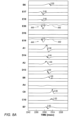
- Figs. 8A and 8B are, respectively, a plot showing of graphs of unipolar EP signals 440 that were acquired by the system of Fig. 1 , and an isochronal map showing respective estimation errors in extracted EP values, in accordance with an exemplary embodiment of the present invention.
- the main concept behind the weighted cost-function DOA model described below is that "sharp" activation is more "reliable” than a shallow activation, where the level of sharpness is defined based dv/dt of the unipolar signal at t i .
- Each t i is mapped to a weight w i between 0 to 1 based on its dv/dt.
- the number near each circle represent the weight of the slope.
- EP signals comprise earliest S-wave patterns, such as in signals 444 sensed by electrodes E19 and E20 (together 448).
- Such negative-slope patterns without signal amplitude first rising as an EP wave approaches an electrode, are indicative of an aberrant focal EP wave propagating away from the electrodes.
- catheter 14 is "right on target," where some of the electrodes are in vicinity of a focal source of Arrhythmia (e.g., distance 60 being smaller that a length of arm 15).
- estimated location 446 of a focal source is at least in part surrounded by measured locations of electrodes 16.
- an iterative DOA estimation process is applied and is described in Figs. 9A and 9B , Figs. 10A and 10B, and Figs. 11A and 11B .
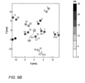
- Figs. 9A and 9B are, respectively, a plot showing graphs of unipolar EP signals having estimation errors 550 higher than a given threshold, and a respective initially estimated location 560 of the focal source in X-Y space, in accordance with an exemplary embodiment of the present invention. Furthermore, some EP values are found within a double potential LAT (such as corrected annotation value 333 of the EP signal of electrode 15 in Fig. 9A ). Also, some EP values (both measured an estimated values) are found between start and end points of unipolar negative deflection (such as within negative deflection 555 of the EP signal of electrode 16 in Fig. 9A )
- location 560 is very close to the location of the distal tip of the catheter, however given the above observations this location is probably wrong.
- processor 22 runs an iterative calculation to estimate the DOA.
- the average estimation error in Fig 9A is 12.4 mSec.
- a local activation time with highest estimation error is removed from DOA estimation. The process is repeated as long as there are more than ten valid local activation time values.
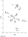
- Fig. 10 is a graph showing the estimated location of focal source 560 of Fig. 9B in nine iterations of the iterative DOA model, in accordance with an exemplary embodiment of the present invention.
- focal source location 560 In the zero and the first iterations, focal source location 560 almost coincides with the location of distal tip 18 of the catheter, however from the second iteration to the 9th iteration the location of focal activity is shifted and finally placed (570) near electrode "1".
- the full circles represent valid electrodes for DOA estimation, while the ring circles represent invalid electrodes.
- the tagging "iter x" beside a ring electrode informs that the specific electrode was eliminated from DOA estimation at iteration x.
- the percentage of invalid segments is a good measure for the "complexity" of the AF in this subject.
- the conduction velocity, CV which also serves as an estimate of the cost in Eq. 4, drops from more than 100mm/mSec to a minimal value of 0.5mm/msec.
- the disclosed iterative model is used in handling acquisitions having noisy waveforms or cases with more than one wave propagating toward the catheter.
- a duration of a typical acquisition is 100-200 msec.
- a typical recording has 30 seconds of unipolar signals and thus contains approximately 120-200 acquisitions. All valid DOA estimates from the approximately 120-200 acquisitions are stored, to be subsequently aggregated, until all acquisitions are processed, and then a statistical method is applied to the corpus of valid DOA estimations.
- processor 22 puts the aggregated DOA and distance values in histograms and statistically analyzes the histograms.
- the processor is configured to derive from the histograms an estimated location by fitting a curve to the histograms and finding the maximum of the curve as a function of estimated DOA and distance.
- Figs. 11A and 11B are histograms 70A and 70B of direction of arrival (DOA) and of histograms 72A and 72B of distance from a focal source, respectively, in accordance with an exemplary embodiment of the present invention.
- DOA direction of arrival
- 72A and 72B distance from a focal source
- the DOA distribution consists of a number of acquisitions per DOA value
- the distance distribution consists of a number of acquisitions per distance value.
- processor 22 compiles (i.e., aggregates) histograms 70A and 70B and histograms 72A and 72B from a number ranging between several tens and several hundred of acquisitions that passed the pre-filtering stage, such shown in Figs. 2 and analyzed in Figs. 3 .
- processor 22 checks first if the DOA distribution, as shown by example in DOA histograms of Figs. 11A and 11B , yields a consistent DOA value.
- consistency test tools include, but are not limited to, constancy estimator and use of confidence interval.
- processor 22 ends the disclosed focal source identification processes.
- processor 22 presents a notice to a user that the process did not identify a focal source of arrhythmogenic activity.
- processor 22 If processor 22 derives a consistent DOA value from the acquisition distribution as a function of DOA, then processor 22 best estimates from the distributions a DOA and s distance to a focal source in question. Processor 22 then uses the best estimated DOA and distance to identify a location of a focal source of arrhythmogenic activity in heart 12 that generated the received EP signals.
- Processor 22 can therefore identify, for that patient, an exitance of a location of focal arrhythmia at a distance of about 300 mm from the location of distal tip 18, at an angle of 0.85 ⁇ relative to the X-axis.
- Fig. 11B shows that most prevalent DOA values of the clinical case analyzed by histogram 70B of Fig. 11B fall about a DOA of 0.5 ⁇ .
- the respective most common distance indicated by histogram 72B is about 300 mm.
- Processor 22 can therefore identify, for that patient, an exitance of a location of focal arrhythmia at a distance of about 300 mm from the location of distal tip 18, at an angle of 0.5 ⁇ relative to the X-axis.
- Fig. 12 is a plot showing DOA clusters analyzed by a k-means clustering model, in accordance with an exemplary embodiment of the present invention.
- the k-means clustering model was applied by processor 22 to a set of DOA values that passed pre-filtering and were aggregated in X-Y space.
- circle represents DOA estimation from an acquisition of LAT values of the numerous acquisitions included in a single recording session.
- a first cluster 80 red circle at (-3.7 mm, -0.2 mm)
- a second cluster 88 has 19.5% of contains 19.5% of DOA in the recording.
- an estimated location of one of the dominant clusters could be projected to the anatomy i.e. the distance from an estimated location, such as an estimated location 84, to the anatomy is less than a given value, e.g., 6 mm, (configurable) then a focal source is identified.
- a focal source is identified.
- the distance from the k-means clustering estimated location 84 to an anatomy location 90, given by the length of an arrow 85 is about 3mm, well below the 6 mm upper limit.
- location 90 was validated by the disclosed technique as a focal source.
- Focal source may also be validated if we find at least 10 indications (configurable) of earliest S-wave patterns in electrodes located within a radius of 6 mm from the focal. It's important to note that foci detection based DOA could manifested in location on the anatomy without placing a catheter in the area of the focal activity, therefore the validation process is optional.
- the exemplary embodiments described herein mainly address cardiac applications, the methods and systems described herein can also be used in other applications, such as in neurology.
- the disclosed methods could also be applied with in any dataset that involves spatiotemporal "cues" for focal activity and a processor is required find this focal activity, for example, for focal estimation of epileptic patients using EEG/MEG.
Landscapes
- Health & Medical Sciences (AREA)
- Life Sciences & Earth Sciences (AREA)
- Engineering & Computer Science (AREA)
- Physics & Mathematics (AREA)
- Surgery (AREA)
- Public Health (AREA)
- General Health & Medical Sciences (AREA)
- Veterinary Medicine (AREA)
- Biomedical Technology (AREA)
- Heart & Thoracic Surgery (AREA)
- Medical Informatics (AREA)
- Molecular Biology (AREA)
- Animal Behavior & Ethology (AREA)
- Pathology (AREA)
- Biophysics (AREA)
- Cardiology (AREA)
- Physiology (AREA)
- General Physics & Mathematics (AREA)
- Signal Processing (AREA)
- Data Mining & Analysis (AREA)
- Artificial Intelligence (AREA)
- Computer Vision & Pattern Recognition (AREA)
- Psychiatry (AREA)
- Mathematical Optimization (AREA)
- Mathematical Analysis (AREA)
- Theoretical Computer Science (AREA)
- Mathematical Physics (AREA)
- Pure & Applied Mathematics (AREA)
- Computational Mathematics (AREA)
- Nuclear Medicine, Radiotherapy & Molecular Imaging (AREA)
- Otolaryngology (AREA)
- Operations Research (AREA)
- Bioinformatics & Cheminformatics (AREA)
- Power Engineering (AREA)
- General Engineering & Computer Science (AREA)
- Probability & Statistics with Applications (AREA)
- Bioinformatics & Computational Biology (AREA)
- Algebra (AREA)
- Evolutionary Biology (AREA)
- Databases & Information Systems (AREA)
Claims (12)
- Prozessorimplementiertes Verfahren zur Fehlerschätzung lokaler Aktivierungszeiten, wobei das Verfahren umfasst:Empfangen einer Sammlung von Erfassungen über eine Mehrzahl von Elektroden (16) in einem Herzen (12), wobei jede Erfassung einen Satz von elektrophysiologischen, EP, Signalen umfasst, die von den Elektroden gemessen werden;Bestimmen einer ursprünglichen Annotation für jedes EP-Signal für die Sammlung von Erfassungen, wobei die ursprüngliche Annotation durch Annotieren jedes EP-Signals mit einer Ankunftszeit der EP-Wellenfront bestimmt wird, wobei das Verfahren für wenigstens einige der Erfassungen ferner umfasst:(i) Schätzen einer jeweiligen Ankunftsrichtung, DOA, und eines jeweiligen Abstands relativ zu den Elektroden, von denen die Sätze von EP-Signalen stammen, für jedes EP-Signal in den wenigstens einigen der Erfassungen; and(ii) Berechnen einer korrigierten Annotation für mindestens ein EP-Signal basierend auf der geschätzten DOA und dem Abstand, wobei die korrigierte Annotation eine Ankunftszeit aufweist, die sich aus einer EP-Wellenfront ergeben hätte, die von einer Fokusquelle mit der geschätzten DOA und dem geschätzten Abstand relativ zu den Elektroden stammt;Schätzen eines Zeitfehlers (550) in dem mindestens einen EP-Signal, wobei der Zeitfehler die Zeitdifferenz zwischen der ursprünglichen Annotation und der korrigierten Annotation ist, wobei das Schätzen des Zeitfehlers umfasst:(i) Auswählen der ursprünglichen Annotation im EP-Signal;(ii) Auswählen der korrigierten Annotation, die der ursprünglichen Annotation entspricht; und(iii) Berechnen der Zeitdifferenz zwischen der ursprünglichen und der korrigierten Annotation;Anpassen des mindestens einen EP-Signals, damit es der geschätzten DOA und dem geschätzten Abstand entspricht und der Fehler korrigiert wird, wobei das Anpassen des mindestens einen EP-Signals das Ersetzen der ursprünglichen Annotation durch die entsprechende korrigierte Annotation umfasst, nachdem verifiziert wurde, dass die korrigierte Annotation eine vordefinierte Bedingung erfüllt; undErstellen einer EP-Karte mindestens eines Teils des Herzens unter Verwendung des Satzes von EP-Signalen, der das angepasste EP-Signal umfasst.
- Prozessorimplementiertes Verfahren nach Anspruch 1, wobei das Erstellen der EP-Karte ein Erstellen einer Karte lokaler Aktivierungszeiten, LAT, umfasst.
- Prozessorimplementiertes Verfahren nach Anspruch 1, wobei das Schätzen der DOA und des Abstands ein Ableiten der DOA und des Abstands umfasst, die eine Kostenfunktion minimieren.
- Prozessorimplementiertes Verfahren nach Anspruch 1, wobei das Verifizieren, dass die korrigierte Annotation die vordefinierte Bedingung erfüllt, ein Verifizieren umfasst, dass die korrigierte Annotation in eine Einsattelung zwischen benachbarten Spitzen im EP-Signal fällt.
- Prozessorimplementiertes Verfahren nach Anspruch 1, wobei das Verifizieren, dass die korrigierte Annotation die vordefinierte Bedingung erfüllt, ein Verifizieren umfasst, dass die korrigierte Annotation und die ursprüngliche Annotation auf einem gleichen monoton abfallenden Segment des EP-Signals liegen.
- Prozessorimplementiertes Verfahren nach Anspruch 1, wobei das Verifizieren, dass die korrigierte Annotation die vordefinierte Bedingung erfüllt, ein Verifizieren umfasst, dass die korrigierte Annotation und die ursprüngliche Annotation auf einem gleichen monotonen Segment des EP-Signals liegen und dass eine Neigung des Segments unter einer vordefinierten Schwellenneigung ist.
- System (10) zur Fehlerschätzung lokaler Aktivierungszeiten, wobei das System umfasst:eine Schnittstelle (34), die so konfiguriert ist, dass sie eine Sammlung von Erfassungen empfängt, die von einer Mehrzahl von Elektroden (16) in einem herzen (12) gesammelt wird, wobei jede Erfassung einen Satz von elektrophysiologischen, EP, Signalen umfasst; undeinen Prozessor (22), der konfiguriert ist zum:Bestimmen einer ursprünglichen Annotation für jedes EP-Signal für die Sammlung von Erfassungen, wobei die ursprüngliche Annotation durch Annotieren jedes EP-Signals mit einer Ankunftszeit der EP-Wellenfronten bestimmt wird, wobei der Vorgang ferner konfiguriert ist zum:(i) Schätzen einer jeweiligen Ankunftsrichtung, DOA, und eines jeweiligen Abstands relativ zu den Elektroden, von denen die Sätze von EP-Signalen stammen, für jedes EP-Signal in den wenigstens einigen der Erfassungen; and(ii) Berechnen einer korrigierten Annotation für mindestens ein EP-Signal basierend auf der geschätzten DOA und dem Abstand mit einer Ankunftszeit, wobei die korrigierte Annotation eine Ankunftszeit aufweist, die sich aus einer EP-Wellenfront ergeben hätte, die von einer Fokusquelle mit der geschätzten DOA und dem geschätzten Abstand relativ zu den Elektroden stammt;Schätzen eines Zeitfehlers (550) in dem mindestens einen EP-Signal, wobei der Zeitfehler die Zeitdifferenz zwischen der ursprünglichen Annotation und der korrigierten Annotation ist, wobei das Schätzen des Zeitfehlers umfasst:(i) Auswählen der ursprünglichen Annotation im EP-Signal;(ii) Auswählen der korrigierten Annotation, die der ursprünglichen Annotation entspricht; und(iii) Berechnen der Zeitdifferenz zwischen der ursprünglichen und der korrigierten Annotation;Anpassen des mindestens einen EP-Signals, damit es der geschätzten DOA und dem geschätzten Abstand entspricht und der Fehler korrigiert wird, wobei das Anpassen des mindestens einen EP-Signals das Ersetzen der ursprünglichen Annotation durch die entsprechende korrigierte Annotation umfasst, nachdem verifiziert wurde, dass die korrigierte Annotation eine vordefinierte Bedingung erfüllt; undErstellen einer EP-Karte mindestens eines Teils des Herzens unter Verwendung des Satzes von EP-Signalen, der das angepasste EP-Signal umfasst.
- System nach Anspruch 7, wobei die EP-Karte eine Karte lokaler Aktivierungszeiten, LAT, umfasst.
- System nach Anspruch 7, wobei der Prozessor so konfiguriert ist, dass er die DOA und den Abstand durch Ableiten der DOA und des Abstands schätzt, die eine Kostenfunktion minimieren.
- System nach Anspruch 7, wobei der Prozessor so konfiguriert ist, dass er durch Verifizieren, dass die korrigierte Annotation in eine Einsattelung zwischen benachbarten Spitzen im EP-Signal fällt, verifiziert, dass die korrigierte Annotation die vordefinierte Bedingung erfüllt.
- System nach Anspruch 7, wobei der Prozessor so konfiguriert ist, dass er durch Verifizieren, dass die korrigierte Annotation und die ursprüngliche Annotation auf einem gleichen monoton fallenden Segment des EP-Signals liegen, verifiziert, dass die korrigierte Annotation die vordefinierte Bedingung erfüllt.
- System nach Anspruch 7, wobei der Prozessor so konfiguriert ist, dass er durch Verifizieren, dass die korrigierte Annotation und die ursprüngliche Annotation auf einem gleichen monotonen Segment des EP-Signals liegen und dass eine Neigung des Segment unter einer vordefinierten Schwellenneigung ist, verifiziert, dass die korrigierte Annotation die vordefinierte Bedingung erfüllt.
Applications Claiming Priority (1)
| Application Number | Priority Date | Filing Date | Title |
|---|---|---|---|
| US16/550,734 US20210059549A1 (en) | 2019-08-26 | 2019-08-26 | Error estimation of local activation times (lat) measured by multiple electrode catheter |
Publications (3)
| Publication Number | Publication Date |
|---|---|
| EP3785609A1 EP3785609A1 (de) | 2021-03-03 |
| EP3785609B1 true EP3785609B1 (de) | 2024-03-06 |
| EP3785609C0 EP3785609C0 (de) | 2024-03-06 |
Family
ID=72145315
Family Applications (1)
| Application Number | Title | Priority Date | Filing Date |
|---|---|---|---|
| EP20191576.6A Active EP3785609B1 (de) | 2019-08-26 | 2020-08-18 | Fehlerschätzung lokaler aktivierungszeiten (lat), die durch einen mehrfachelektrodenkatheter gemessen werden |
Country Status (7)
| Country | Link |
|---|---|
| US (1) | US20210059549A1 (de) |
| EP (1) | EP3785609B1 (de) |
| JP (1) | JP7605426B2 (de) |
| KR (1) | KR102855751B1 (de) |
| CN (1) | CN112494050B (de) |
| IL (1) | IL276306B2 (de) |
| RU (1) | RU2756366C1 (de) |
Families Citing this family (36)
| Publication number | Priority date | Publication date | Assignee | Title |
|---|---|---|---|---|
| US10905329B2 (en) | 2016-06-09 | 2021-02-02 | Biosense Webster (Israel) Ltd. | Multi-function conducting elements for a catheter |
| US12029545B2 (en) | 2017-05-30 | 2024-07-09 | Biosense Webster (Israel) Ltd. | Catheter splines as location sensors |
| US20190314083A1 (en) | 2018-04-11 | 2019-10-17 | Biosense Webster (Israel) Ltd. | Flexible Multi-Arm Catheter with Diametrically Opposed Sensing Electrodes |
| US11045628B2 (en) | 2018-12-11 | 2021-06-29 | Biosense Webster (Israel) Ltd. | Balloon catheter with high articulation |
| US11207016B2 (en) | 2018-12-28 | 2021-12-28 | Biosense Webster (Israel) Ltd. | Mapping ECG signals using a multipole electrode assembly |
| US11850051B2 (en) | 2019-04-30 | 2023-12-26 | Biosense Webster (Israel) Ltd. | Mapping grid with high density electrode array |
| US11712172B2 (en) | 2019-07-18 | 2023-08-01 | Biosense Webster (Israel) Ltd. | Visual guidance for positioning a distal end of a medical probe |
| US11116435B2 (en) * | 2019-08-26 | 2021-09-14 | Biosense Webster (Israel) Ltd. | Automatic identification of a location of focal source in atrial fibrillation (AF) |
| US11759150B2 (en) | 2019-08-27 | 2023-09-19 | Biosense Webster (Israel) Ltd. | Accurate basket catheter tracking |
| CA3094535A1 (en) * | 2019-09-27 | 2021-03-27 | Queen's University At Kingston | Sequential mapping of cardiac arrhythmia without fiducial time reference |
| US11950930B2 (en) | 2019-12-12 | 2024-04-09 | Biosense Webster (Israel) Ltd. | Multi-dimensional acquisition of bipolar signals from a catheter |
| US11517218B2 (en) | 2019-12-20 | 2022-12-06 | Biosense Webster (Israel) Ltd. | Selective graphical presentation of electrophysiological parameters |
| US12232874B2 (en) | 2020-05-29 | 2025-02-25 | Biosense Webster (Israel) Ltd. | Electrode apparatus for diagnosis of arrhythmias |
| US11987017B2 (en) | 2020-06-08 | 2024-05-21 | Biosense Webster (Israel) Ltd. | Features to assist in assembly and testing of devices |
| US12048479B2 (en) | 2020-09-10 | 2024-07-30 | Biosense Webster (Israel) Ltd. | Surface mounted electrode catheter |
| US11950840B2 (en) | 2020-09-22 | 2024-04-09 | Biosense Webster (Israel) Ltd. | Basket catheter having insulated ablation electrodes |
| US11950841B2 (en) | 2020-09-22 | 2024-04-09 | Biosense Webster (Israel) Ltd. | Basket catheter having insulated ablation electrodes and diagnostic electrodes |
| US12082875B2 (en) | 2020-09-24 | 2024-09-10 | Biosense Webster (Israel) Ltd | Balloon catheter having a coil for sensing tissue temperature and position of the balloon |
| US11974803B2 (en) | 2020-10-12 | 2024-05-07 | Biosense Webster (Israel) Ltd. | Basket catheter with balloon |
| US12201786B2 (en) | 2020-12-17 | 2025-01-21 | Biosense Webster (Israel) Ltd. | Measurement of distal end dimension of catheters using magnetic fields |
| US11918383B2 (en) | 2020-12-21 | 2024-03-05 | Biosense Webster (Israel) Ltd. | Visualizing performance of catheter electrodes |
| US12064170B2 (en) | 2021-05-13 | 2024-08-20 | Biosense Webster (Israel) Ltd. | Distal assembly for catheter with lumens running along spines |
| US12364426B2 (en) * | 2021-08-12 | 2025-07-22 | Biosense Webster (Israel) Ltd. | Electro-anatomical mapping and annotation presented in electrophysiological procedures |
| US12004804B2 (en) | 2021-09-09 | 2024-06-11 | Biosense Webster (Israel) Ltd. | Basket catheter with mushroom shape distal tip |
| US12478424B2 (en) | 2021-09-10 | 2025-11-25 | Biosense Webster (Israel) Ltd. | Staggered pairs of biased ablation electrodes on basket catheter |
| US12011280B2 (en) | 2021-10-04 | 2024-06-18 | Biosense Webster (Israel) Ltd. | Electrophysiological mapping in the presence of injury current |
| US12533489B2 (en) | 2021-10-08 | 2026-01-27 | Biosense Webster (Israel) Ltd. | Measuring tissue proximity for multi-electrode catheter |
| US12419683B2 (en) | 2021-12-22 | 2025-09-23 | Biosense Webster (Israel) Ltd. | Irreversible electroporation with shorted electrodes |
| US12484961B2 (en) | 2022-01-20 | 2025-12-02 | Biosense Webster (Israel) Ltd. | Mechanical retainer systems for electrodes of a basket catheter, and methods of the same |
| US12446946B2 (en) | 2022-01-20 | 2025-10-21 | Biosense Webster (Israel) Ltd. | Systems and methods for a single spiral electrode assembly forming a spherical basket for improved tissue contact and current delivery |
| US12440263B2 (en) | 2022-01-20 | 2025-10-14 | Biosense Webster (Israel) Ltd. | Systems and methods for tripodic spines forming a spherical basket for improved tissue contact and current delivery |
| US12471989B2 (en) | 2022-04-28 | 2025-11-18 | Biosense Webster (Israel) Ltd. | Strengthened expandable baskets for medical probes and medical probes containing strengthen expandable baskets |
| US20240206978A1 (en) * | 2022-12-27 | 2024-06-27 | Biosense Webster (Israel) Ltd. | Electrophysiology mapping using catheter splines deflection modeling |
| US12533185B2 (en) | 2022-12-28 | 2026-01-27 | Biosense Webster (Israel) Ltd. | Basket end effector with distal position sensor |
| US12521035B2 (en) | 2022-12-29 | 2026-01-13 | Biosense Webster (Israel) Ltd. | Cylindrical cage systems and methods for distributed tissue contact for mapping and ablation |
| GB202301045D0 (en) * | 2023-01-25 | 2023-03-08 | Univ Oxford Innovation Ltd | Neural source localisation for optimisation of deep brain stimulation |
Family Cites Families (25)
| Publication number | Priority date | Publication date | Assignee | Title |
|---|---|---|---|---|
| US4975710A (en) * | 1989-08-01 | 1990-12-04 | Baghdady Elie J | Methods and apparatus for direction of arrival measurement and radio navigation aids |
| AU697414B2 (en) * | 1995-04-20 | 1998-10-08 | Jawahar M. Desai | Apparatus for cardiac mapping and ablation |
| US6226542B1 (en) | 1998-07-24 | 2001-05-01 | Biosense, Inc. | Three-dimensional reconstruction of intrabody organs |
| US6301496B1 (en) | 1998-07-24 | 2001-10-09 | Biosense, Inc. | Vector mapping of three-dimensionally reconstructed intrabody organs and method of display |
| US6892091B1 (en) | 2000-02-18 | 2005-05-10 | Biosense, Inc. | Catheter, method and apparatus for generating an electrical map of a chamber of the heart |
| US6847839B2 (en) | 2001-07-30 | 2005-01-25 | The Trustees Of Columbia University In The City Of New York | System and method for determining reentrant ventricular tachycardia isthmus location and shape for catheter ablation |
| CN100399730C (zh) * | 2003-12-03 | 2008-07-02 | 电子科技大学 | 一种阵列天线通道误差的盲估计方法 |
| US7536218B2 (en) | 2005-07-15 | 2009-05-19 | Biosense Webster, Inc. | Hybrid magnetic-based and impedance-based position sensing |
| US7756576B2 (en) | 2005-08-26 | 2010-07-13 | Biosense Webster, Inc. | Position sensing and detection of skin impedance |
| US8986298B2 (en) * | 2006-11-17 | 2015-03-24 | Biosense Webster, Inc. | Catheter with omni-directional optical tip having isolated optical paths |
| US8456182B2 (en) | 2008-09-30 | 2013-06-04 | Biosense Webster, Inc. | Current localization tracker |
| KR101046510B1 (ko) * | 2008-11-07 | 2011-07-04 | 금오공과대학교 산학협력단 | 에지 분류 및 영역 확장 기법을 통한 심실 자동 분할 방법 |
| US8948837B2 (en) * | 2011-01-13 | 2015-02-03 | Rhythmia Medical, Inc. | Electroanatomical mapping |
| US8700136B2 (en) | 2011-11-11 | 2014-04-15 | Biosense Webster (Israel), Ltd. | Accurate time annotation of intracardiac ECG signals |
| EP3073907B1 (de) * | 2014-02-25 | 2020-06-17 | St. Jude Medical, Cardiology Division, Inc. | System zur lokalen elektrophysiologischen charakterisierung eines kardialen substrats mit mehrfachelektrodenkathetern |
| US9259165B2 (en) * | 2014-02-26 | 2016-02-16 | Biosense Webster (Israel) Ltd. | Determination of reference annotation time from multi-channel electro-cardiogram signals |
| EP3125757B1 (de) * | 2014-03-31 | 2024-03-06 | University Health Network | Verfahren zur fokusquellenidentifikation |
| US9730603B2 (en) | 2014-06-20 | 2017-08-15 | Boston Scientific Scimed Inc. | Medical devices for mapping cardiac tissue |
| US10506939B2 (en) | 2015-08-11 | 2019-12-17 | Biosense Webster (Israel) Ltd. | Matching and tracking time sequences of heart activation |
| US11006887B2 (en) | 2016-01-14 | 2021-05-18 | Biosense Webster (Israel) Ltd. | Region of interest focal source detection using comparisons of R-S wave magnitudes and LATs of RS complexes |
| US10517496B2 (en) * | 2016-01-14 | 2019-12-31 | Biosense Webster (Israel) Ltd. | Region of interest focal source detection |
| US10136828B2 (en) | 2016-03-31 | 2018-11-27 | Biosense Webster (Israel) Ltd. | Mapping of atrial fibrillation |
| CN106950528B (zh) * | 2017-03-24 | 2019-12-10 | 杭州电子科技大学 | 一种基于线性调频信号的波达方向估计方法 |
| US20190216347A1 (en) * | 2018-01-16 | 2019-07-18 | Boston Scientific Scimed Inc. | Systems and methods for activation mapping of the heart without the use of a reference catheter |
| US11350867B2 (en) * | 2018-04-27 | 2022-06-07 | Duke University | Small-scale time delay and single-shot conduction velocity analysis and mapping for cardiac electrophysiology |
-
2019
- 2019-08-26 US US16/550,734 patent/US20210059549A1/en active Pending
-
2020
- 2020-07-26 IL IL276306A patent/IL276306B2/en unknown
- 2020-07-28 KR KR1020200093650A patent/KR102855751B1/ko active Active
- 2020-08-18 EP EP20191576.6A patent/EP3785609B1/de active Active
- 2020-08-19 RU RU2020127603A patent/RU2756366C1/ru active
- 2020-08-25 JP JP2020141630A patent/JP7605426B2/ja active Active
- 2020-08-26 CN CN202010875193.0A patent/CN112494050B/zh active Active
Also Published As
| Publication number | Publication date |
|---|---|
| RU2756366C1 (ru) | 2021-09-29 |
| JP7605426B2 (ja) | 2024-12-24 |
| JP2021030085A (ja) | 2021-03-01 |
| IL276306B1 (en) | 2024-06-01 |
| CN112494050A (zh) | 2021-03-16 |
| US20210059549A1 (en) | 2021-03-04 |
| KR20210027077A (ko) | 2021-03-10 |
| KR102855751B1 (ko) | 2025-09-09 |
| EP3785609A1 (de) | 2021-03-03 |
| IL276306A (en) | 2021-03-01 |
| IL276306B2 (en) | 2024-10-01 |
| CN112494050B (zh) | 2025-09-02 |
| EP3785609C0 (de) | 2024-03-06 |
Similar Documents
| Publication | Publication Date | Title |
|---|---|---|
| EP3785609B1 (de) | Fehlerschätzung lokaler aktivierungszeiten (lat), die durch einen mehrfachelektrodenkatheter gemessen werden | |
| EP3808272B1 (de) | Automatische identifizierung eines standorts einer fokalen quelle bei vorhofflimmern (af) | |
| EP3818938B1 (de) | Verwendung von statistischen eigenschaften mehrerer gruppierter ekg-signale zur detektion inkonsistenter signale | |
| CN113208604A (zh) | 自动图案采集 | |
| EP2996547B1 (de) | Erweiterte aktivierungsanfangszeitoptimierung durch ähnlichkeitsbasierten mustervergleich | |
| EP2591721A1 (de) | Präzise Zeitaufnahme von intrakardialen EKG-Signalen | |
| JP7114303B2 (ja) | 組織伝導速度 | |
| EP3834727B1 (de) | Detektion von ventrikulärer aktivität unter verwendung von unipolaren und bipolaren signalen | |
| EP4108174B1 (de) | Verbesserung der abbildungsauflösung einer elektrophysiologischen welle, die sich auf der oberfläche des herzens eines patienten ausbreitet | |
| EP4566533A1 (de) | Atmungskompensation für mapping | |
| EP3932313A1 (de) | Analyse von mehreren elektrodenkathetersignalen zur bestimmung des elektrophysiologischen (ep) wellenausbreitungsvektors |
Legal Events
| Date | Code | Title | Description |
|---|---|---|---|
| PUAI | Public reference made under article 153(3) epc to a published international application that has entered the european phase |
Free format text: ORIGINAL CODE: 0009012 |
|
| STAA | Information on the status of an ep patent application or granted ep patent |
Free format text: STATUS: THE APPLICATION HAS BEEN PUBLISHED |
|
| AK | Designated contracting states |
Kind code of ref document: A1 Designated state(s): AL AT BE BG CH CY CZ DE DK EE ES FI FR GB GR HR HU IE IS IT LI LT LU LV MC MK MT NL NO PL PT RO RS SE SI SK SM TR |
|
| AX | Request for extension of the european patent |
Extension state: BA ME |
|
| STAA | Information on the status of an ep patent application or granted ep patent |
Free format text: STATUS: REQUEST FOR EXAMINATION WAS MADE |
|
| 17P | Request for examination filed |
Effective date: 20210903 |
|
| RBV | Designated contracting states (corrected) |
Designated state(s): AL AT BE BG CH CY CZ DE DK EE ES FI FR GB GR HR HU IE IS IT LI LT LU LV MC MK MT NL NO PL PT RO RS SE SI SK SM TR |
|
| RAP3 | Party data changed (applicant data changed or rights of an application transferred) |
Owner name: BIOSENSE WEBSTER (ISRAEL) LTD. |
|
| REG | Reference to a national code |
Ref country code: DE Ref legal event code: R079 Free format text: PREVIOUS MAIN CLASS: A61B0005000000 Ipc: A61B0005287000 Ref document number: 602020026697 Country of ref document: DE |
|
| GRAP | Despatch of communication of intention to grant a patent |
Free format text: ORIGINAL CODE: EPIDOSNIGR1 |
|
| STAA | Information on the status of an ep patent application or granted ep patent |
Free format text: STATUS: GRANT OF PATENT IS INTENDED |
|
| RIC1 | Information provided on ipc code assigned before grant |
Ipc: A61B 5/349 20210101ALI20230516BHEP Ipc: A61B 5/287 20210101AFI20230516BHEP |
|
| INTG | Intention to grant announced |
Effective date: 20230606 |
|
| GRAJ | Information related to disapproval of communication of intention to grant by the applicant or resumption of examination proceedings by the epo deleted |
Free format text: ORIGINAL CODE: EPIDOSDIGR1 |
|
| STAA | Information on the status of an ep patent application or granted ep patent |
Free format text: STATUS: REQUEST FOR EXAMINATION WAS MADE |
|
| INTC | Intention to grant announced (deleted) | ||
| GRAP | Despatch of communication of intention to grant a patent |
Free format text: ORIGINAL CODE: EPIDOSNIGR1 |
|
| STAA | Information on the status of an ep patent application or granted ep patent |
Free format text: STATUS: GRANT OF PATENT IS INTENDED |
|
| INTG | Intention to grant announced |
Effective date: 20231110 |
|
| GRAS | Grant fee paid |
Free format text: ORIGINAL CODE: EPIDOSNIGR3 |
|
| GRAA | (expected) grant |
Free format text: ORIGINAL CODE: 0009210 |
|
| STAA | Information on the status of an ep patent application or granted ep patent |
Free format text: STATUS: THE PATENT HAS BEEN GRANTED |
|
| AK | Designated contracting states |
Kind code of ref document: B1 Designated state(s): AL AT BE BG CH CY CZ DE DK EE ES FI FR GB GR HR HU IE IS IT LI LT LU LV MC MK MT NL NO PL PT RO RS SE SI SK SM TR |
|
| REG | Reference to a national code |
Ref country code: CH Ref legal event code: EP |
|
| REG | Reference to a national code |
Ref country code: IE Ref legal event code: FG4D |
|
| REG | Reference to a national code |
Ref country code: DE Ref legal event code: R096 Ref document number: 602020026697 Country of ref document: DE |
|
| U01 | Request for unitary effect filed |
Effective date: 20240403 |
|
| U07 | Unitary effect registered |
Designated state(s): AT BE BG DE DK EE FI FR IT LT LU LV MT NL PT SE SI Effective date: 20240411 |
|
| PG25 | Lapsed in a contracting state [announced via postgrant information from national office to epo] |
Ref country code: GR Free format text: LAPSE BECAUSE OF FAILURE TO SUBMIT A TRANSLATION OF THE DESCRIPTION OR TO PAY THE FEE WITHIN THE PRESCRIBED TIME-LIMIT Effective date: 20240607 |
|
| PG25 | Lapsed in a contracting state [announced via postgrant information from national office to epo] |
Ref country code: HR Free format text: LAPSE BECAUSE OF FAILURE TO SUBMIT A TRANSLATION OF THE DESCRIPTION OR TO PAY THE FEE WITHIN THE PRESCRIBED TIME-LIMIT Effective date: 20240306 Ref country code: RS Free format text: LAPSE BECAUSE OF FAILURE TO SUBMIT A TRANSLATION OF THE DESCRIPTION OR TO PAY THE FEE WITHIN THE PRESCRIBED TIME-LIMIT Effective date: 20240606 |
|
| PG25 | Lapsed in a contracting state [announced via postgrant information from national office to epo] |
Ref country code: ES Free format text: LAPSE BECAUSE OF FAILURE TO SUBMIT A TRANSLATION OF THE DESCRIPTION OR TO PAY THE FEE WITHIN THE PRESCRIBED TIME-LIMIT Effective date: 20240306 |
|
| PG25 | Lapsed in a contracting state [announced via postgrant information from national office to epo] |
Ref country code: RS Free format text: LAPSE BECAUSE OF FAILURE TO SUBMIT A TRANSLATION OF THE DESCRIPTION OR TO PAY THE FEE WITHIN THE PRESCRIBED TIME-LIMIT Effective date: 20240606 Ref country code: NO Free format text: LAPSE BECAUSE OF FAILURE TO SUBMIT A TRANSLATION OF THE DESCRIPTION OR TO PAY THE FEE WITHIN THE PRESCRIBED TIME-LIMIT Effective date: 20240606 Ref country code: HR Free format text: LAPSE BECAUSE OF FAILURE TO SUBMIT A TRANSLATION OF THE DESCRIPTION OR TO PAY THE FEE WITHIN THE PRESCRIBED TIME-LIMIT Effective date: 20240306 Ref country code: GR Free format text: LAPSE BECAUSE OF FAILURE TO SUBMIT A TRANSLATION OF THE DESCRIPTION OR TO PAY THE FEE WITHIN THE PRESCRIBED TIME-LIMIT Effective date: 20240607 Ref country code: ES Free format text: LAPSE BECAUSE OF FAILURE TO SUBMIT A TRANSLATION OF THE DESCRIPTION OR TO PAY THE FEE WITHIN THE PRESCRIBED TIME-LIMIT Effective date: 20240306 |
|
| U20 | Renewal fee for the european patent with unitary effect paid |
Year of fee payment: 5 Effective date: 20240705 |
|
| PG25 | Lapsed in a contracting state [announced via postgrant information from national office to epo] |
Ref country code: IS Free format text: LAPSE BECAUSE OF FAILURE TO SUBMIT A TRANSLATION OF THE DESCRIPTION OR TO PAY THE FEE WITHIN THE PRESCRIBED TIME-LIMIT Effective date: 20240706 |
|
| PG25 | Lapsed in a contracting state [announced via postgrant information from national office to epo] |
Ref country code: SM Free format text: LAPSE BECAUSE OF FAILURE TO SUBMIT A TRANSLATION OF THE DESCRIPTION OR TO PAY THE FEE WITHIN THE PRESCRIBED TIME-LIMIT Effective date: 20240306 |
|
| PG25 | Lapsed in a contracting state [announced via postgrant information from national office to epo] |
Ref country code: CZ Free format text: LAPSE BECAUSE OF FAILURE TO SUBMIT A TRANSLATION OF THE DESCRIPTION OR TO PAY THE FEE WITHIN THE PRESCRIBED TIME-LIMIT Effective date: 20240306 |
|
| PG25 | Lapsed in a contracting state [announced via postgrant information from national office to epo] |
Ref country code: PL Free format text: LAPSE BECAUSE OF FAILURE TO SUBMIT A TRANSLATION OF THE DESCRIPTION OR TO PAY THE FEE WITHIN THE PRESCRIBED TIME-LIMIT Effective date: 20240306 |
|
| PG25 | Lapsed in a contracting state [announced via postgrant information from national office to epo] |
Ref country code: SK Free format text: LAPSE BECAUSE OF FAILURE TO SUBMIT A TRANSLATION OF THE DESCRIPTION OR TO PAY THE FEE WITHIN THE PRESCRIBED TIME-LIMIT Effective date: 20240306 |
|
| PG25 | Lapsed in a contracting state [announced via postgrant information from national office to epo] |
Ref country code: SM Free format text: LAPSE BECAUSE OF FAILURE TO SUBMIT A TRANSLATION OF THE DESCRIPTION OR TO PAY THE FEE WITHIN THE PRESCRIBED TIME-LIMIT Effective date: 20240306 Ref country code: SK Free format text: LAPSE BECAUSE OF FAILURE TO SUBMIT A TRANSLATION OF THE DESCRIPTION OR TO PAY THE FEE WITHIN THE PRESCRIBED TIME-LIMIT Effective date: 20240306 Ref country code: RO Free format text: LAPSE BECAUSE OF FAILURE TO SUBMIT A TRANSLATION OF THE DESCRIPTION OR TO PAY THE FEE WITHIN THE PRESCRIBED TIME-LIMIT Effective date: 20240306 Ref country code: PL Free format text: LAPSE BECAUSE OF FAILURE TO SUBMIT A TRANSLATION OF THE DESCRIPTION OR TO PAY THE FEE WITHIN THE PRESCRIBED TIME-LIMIT Effective date: 20240306 Ref country code: IS Free format text: LAPSE BECAUSE OF FAILURE TO SUBMIT A TRANSLATION OF THE DESCRIPTION OR TO PAY THE FEE WITHIN THE PRESCRIBED TIME-LIMIT Effective date: 20240706 Ref country code: CZ Free format text: LAPSE BECAUSE OF FAILURE TO SUBMIT A TRANSLATION OF THE DESCRIPTION OR TO PAY THE FEE WITHIN THE PRESCRIBED TIME-LIMIT Effective date: 20240306 |
|
| REG | Reference to a national code |
Ref country code: DE Ref legal event code: R097 Ref document number: 602020026697 Country of ref document: DE |
|
| PLBE | No opposition filed within time limit |
Free format text: ORIGINAL CODE: 0009261 |
|
| STAA | Information on the status of an ep patent application or granted ep patent |
Free format text: STATUS: NO OPPOSITION FILED WITHIN TIME LIMIT |
|
| 26N | No opposition filed |
Effective date: 20241209 |
|
| REG | Reference to a national code |
Ref country code: CH Ref legal event code: PL |
|
| PG25 | Lapsed in a contracting state [announced via postgrant information from national office to epo] |
Ref country code: MC Free format text: LAPSE BECAUSE OF FAILURE TO SUBMIT A TRANSLATION OF THE DESCRIPTION OR TO PAY THE FEE WITHIN THE PRESCRIBED TIME-LIMIT Effective date: 20240306 Ref country code: CH Free format text: LAPSE BECAUSE OF NON-PAYMENT OF DUE FEES Effective date: 20240831 |
|
| PG25 | Lapsed in a contracting state [announced via postgrant information from national office to epo] |
Ref country code: IE Free format text: LAPSE BECAUSE OF NON-PAYMENT OF DUE FEES Effective date: 20240818 |
|
| U20 | Renewal fee for the european patent with unitary effect paid |
Year of fee payment: 6 Effective date: 20250709 |
|
| PGFP | Annual fee paid to national office [announced via postgrant information from national office to epo] |
Ref country code: GB Payment date: 20250703 Year of fee payment: 6 |
|
| PG25 | Lapsed in a contracting state [announced via postgrant information from national office to epo] |
Ref country code: CY Free format text: LAPSE BECAUSE OF FAILURE TO SUBMIT A TRANSLATION OF THE DESCRIPTION OR TO PAY THE FEE WITHIN THE PRESCRIBED TIME-LIMIT; INVALID AB INITIO Effective date: 20200818 |
|
| PG25 | Lapsed in a contracting state [announced via postgrant information from national office to epo] |
Ref country code: HU Free format text: LAPSE BECAUSE OF FAILURE TO SUBMIT A TRANSLATION OF THE DESCRIPTION OR TO PAY THE FEE WITHIN THE PRESCRIBED TIME-LIMIT; INVALID AB INITIO Effective date: 20200818 |