EP3785802A1 - Ventil, system zur auftragung eines beschichtungsprodukts, das ein solches ventil umfasst, und werkzeug für dessen montage und demontage - Google Patents
Ventil, system zur auftragung eines beschichtungsprodukts, das ein solches ventil umfasst, und werkzeug für dessen montage und demontage Download PDFInfo
- Publication number
- EP3785802A1 EP3785802A1 EP20193810.7A EP20193810A EP3785802A1 EP 3785802 A1 EP3785802 A1 EP 3785802A1 EP 20193810 A EP20193810 A EP 20193810A EP 3785802 A1 EP3785802 A1 EP 3785802A1
- Authority
- EP
- European Patent Office
- Prior art keywords
- valve
- profile
- tool
- peripheral
- protruding
- Prior art date
- Legal status (The legal status is an assumption and is not a legal conclusion. Google has not performed a legal analysis and makes no representation as to the accuracy of the status listed.)
- Granted
Links
Images




Classifications
-
- B—PERFORMING OPERATIONS; TRANSPORTING
- B05—SPRAYING OR ATOMISING IN GENERAL; APPLYING FLUENT MATERIALS TO SURFACES, IN GENERAL
- B05B—SPRAYING APPARATUS; ATOMISING APPARATUS; NOZZLES
- B05B15/00—Details of spraying plant or spraying apparatus not otherwise provided for; Accessories
- B05B15/60—Arrangements for mounting, supporting or holding spraying apparatus
- B05B15/65—Mounting arrangements for fluid connection of the spraying apparatus or its outlets to flow conduits
-
- B—PERFORMING OPERATIONS; TRANSPORTING
- B05—SPRAYING OR ATOMISING IN GENERAL; APPLYING FLUENT MATERIALS TO SURFACES, IN GENERAL
- B05B—SPRAYING APPARATUS; ATOMISING APPARATUS; NOZZLES
- B05B1/00—Nozzles, spray heads or other outlets, with or without auxiliary devices such as valves, heating means
- B05B1/30—Nozzles, spray heads or other outlets, with or without auxiliary devices such as valves, heating means designed to control volume of flow, e.g. with adjustable passages
- B05B1/3033—Nozzles, spray heads or other outlets, with or without auxiliary devices such as valves, heating means designed to control volume of flow, e.g. with adjustable passages the control being effected by relative coaxial longitudinal movement of the controlling element and the spray head
- B05B1/304—Nozzles, spray heads or other outlets, with or without auxiliary devices such as valves, heating means designed to control volume of flow, e.g. with adjustable passages the control being effected by relative coaxial longitudinal movement of the controlling element and the spray head the controlling element being a lift valve
- B05B1/3046—Nozzles, spray heads or other outlets, with or without auxiliary devices such as valves, heating means designed to control volume of flow, e.g. with adjustable passages the control being effected by relative coaxial longitudinal movement of the controlling element and the spray head the controlling element being a lift valve the valve element, e.g. a needle, co-operating with a valve seat located downstream of the valve element and its actuating means, generally in the proximity of the outlet orifice
-
- B—PERFORMING OPERATIONS; TRANSPORTING
- B05—SPRAYING OR ATOMISING IN GENERAL; APPLYING FLUENT MATERIALS TO SURFACES, IN GENERAL
- B05B—SPRAYING APPARATUS; ATOMISING APPARATUS; NOZZLES
- B05B1/00—Nozzles, spray heads or other outlets, with or without auxiliary devices such as valves, heating means
- B05B1/30—Nozzles, spray heads or other outlets, with or without auxiliary devices such as valves, heating means designed to control volume of flow, e.g. with adjustable passages
- B05B1/3033—Nozzles, spray heads or other outlets, with or without auxiliary devices such as valves, heating means designed to control volume of flow, e.g. with adjustable passages the control being effected by relative coaxial longitudinal movement of the controlling element and the spray head
- B05B1/304—Nozzles, spray heads or other outlets, with or without auxiliary devices such as valves, heating means designed to control volume of flow, e.g. with adjustable passages the control being effected by relative coaxial longitudinal movement of the controlling element and the spray head the controlling element being a lift valve
- B05B1/3046—Nozzles, spray heads or other outlets, with or without auxiliary devices such as valves, heating means designed to control volume of flow, e.g. with adjustable passages the control being effected by relative coaxial longitudinal movement of the controlling element and the spray head the controlling element being a lift valve the valve element, e.g. a needle, co-operating with a valve seat located downstream of the valve element and its actuating means, generally in the proximity of the outlet orifice
- B05B1/306—Nozzles, spray heads or other outlets, with or without auxiliary devices such as valves, heating means designed to control volume of flow, e.g. with adjustable passages the control being effected by relative coaxial longitudinal movement of the controlling element and the spray head the controlling element being a lift valve the valve element, e.g. a needle, co-operating with a valve seat located downstream of the valve element and its actuating means, generally in the proximity of the outlet orifice the actuating means being a fluid
-
- F—MECHANICAL ENGINEERING; LIGHTING; HEATING; WEAPONS; BLASTING
- F16—ENGINEERING ELEMENTS AND UNITS; GENERAL MEASURES FOR PRODUCING AND MAINTAINING EFFECTIVE FUNCTIONING OF MACHINES OR INSTALLATIONS; THERMAL INSULATION IN GENERAL
- F16K—VALVES; TAPS; COCKS; ACTUATING-FLOATS; DEVICES FOR VENTING OR AERATING
- F16K37/00—Special means in or on valves or other cut-off apparatus for indicating or recording operation thereof, or for enabling an alarm to be given
-
- B—PERFORMING OPERATIONS; TRANSPORTING
- B05—SPRAYING OR ATOMISING IN GENERAL; APPLYING FLUENT MATERIALS TO SURFACES, IN GENERAL
- B05B—SPRAYING APPARATUS; ATOMISING APPARATUS; NOZZLES
- B05B1/00—Nozzles, spray heads or other outlets, with or without auxiliary devices such as valves, heating means
- B05B1/30—Nozzles, spray heads or other outlets, with or without auxiliary devices such as valves, heating means designed to control volume of flow, e.g. with adjustable passages
- B05B1/3006—Nozzles, spray heads or other outlets, with or without auxiliary devices such as valves, heating means designed to control volume of flow, e.g. with adjustable passages the controlling element being actuated by the pressure of the fluid to be sprayed
-
- B—PERFORMING OPERATIONS; TRANSPORTING
- B05—SPRAYING OR ATOMISING IN GENERAL; APPLYING FLUENT MATERIALS TO SURFACES, IN GENERAL
- B05B—SPRAYING APPARATUS; ATOMISING APPARATUS; NOZZLES
- B05B1/00—Nozzles, spray heads or other outlets, with or without auxiliary devices such as valves, heating means
- B05B1/30—Nozzles, spray heads or other outlets, with or without auxiliary devices such as valves, heating means designed to control volume of flow, e.g. with adjustable passages
- B05B1/3013—Lift valves
-
- B—PERFORMING OPERATIONS; TRANSPORTING
- B05—SPRAYING OR ATOMISING IN GENERAL; APPLYING FLUENT MATERIALS TO SURFACES, IN GENERAL
- B05B—SPRAYING APPARATUS; ATOMISING APPARATUS; NOZZLES
- B05B1/00—Nozzles, spray heads or other outlets, with or without auxiliary devices such as valves, heating means
- B05B1/30—Nozzles, spray heads or other outlets, with or without auxiliary devices such as valves, heating means designed to control volume of flow, e.g. with adjustable passages
- B05B1/3026—Gate valves; Sliding valves; Cocks
-
- B—PERFORMING OPERATIONS; TRANSPORTING
- B05—SPRAYING OR ATOMISING IN GENERAL; APPLYING FLUENT MATERIALS TO SURFACES, IN GENERAL
- B05B—SPRAYING APPARATUS; ATOMISING APPARATUS; NOZZLES
- B05B1/00—Nozzles, spray heads or other outlets, with or without auxiliary devices such as valves, heating means
- B05B1/30—Nozzles, spray heads or other outlets, with or without auxiliary devices such as valves, heating means designed to control volume of flow, e.g. with adjustable passages
- B05B1/32—Nozzles, spray heads or other outlets, with or without auxiliary devices such as valves, heating means designed to control volume of flow, e.g. with adjustable passages in which a valve member forms part of the outlet opening
-
- B—PERFORMING OPERATIONS; TRANSPORTING
- B05—SPRAYING OR ATOMISING IN GENERAL; APPLYING FLUENT MATERIALS TO SURFACES, IN GENERAL
- B05B—SPRAYING APPARATUS; ATOMISING APPARATUS; NOZZLES
- B05B1/00—Nozzles, spray heads or other outlets, with or without auxiliary devices such as valves, heating means
- B05B1/30—Nozzles, spray heads or other outlets, with or without auxiliary devices such as valves, heating means designed to control volume of flow, e.g. with adjustable passages
- B05B1/32—Nozzles, spray heads or other outlets, with or without auxiliary devices such as valves, heating means designed to control volume of flow, e.g. with adjustable passages in which a valve member forms part of the outlet opening
- B05B1/326—Gate valves; Sliding valves; Cocks
-
- B—PERFORMING OPERATIONS; TRANSPORTING
- B05—SPRAYING OR ATOMISING IN GENERAL; APPLYING FLUENT MATERIALS TO SURFACES, IN GENERAL
- B05B—SPRAYING APPARATUS; ATOMISING APPARATUS; NOZZLES
- B05B11/00—Single-unit hand-held apparatus in which flow of contents is produced by the muscular force of the operator at the moment of use
- B05B11/01—Single-unit hand-held apparatus in which flow of contents is produced by the muscular force of the operator at the moment of use characterised by the means producing the flow
- B05B11/10—Pump arrangements for transferring the contents from the container to a pump chamber by a sucking effect and forcing the contents out through the dispensing nozzle
-
- B—PERFORMING OPERATIONS; TRANSPORTING
- B05—SPRAYING OR ATOMISING IN GENERAL; APPLYING FLUENT MATERIALS TO SURFACES, IN GENERAL
- B05B—SPRAYING APPARATUS; ATOMISING APPARATUS; NOZZLES
- B05B7/00—Spraying apparatus for discharge of liquids or other fluent materials from two or more sources, e.g. of liquid and air, of powder and gas
- B05B7/02—Spray pistols; Apparatus for discharge
- B05B7/12—Spray pistols; Apparatus for discharge designed to control volume of flow, e.g. with adjustable passages
-
- B—PERFORMING OPERATIONS; TRANSPORTING
- B25—HAND TOOLS; PORTABLE POWER-DRIVEN TOOLS; MANIPULATORS
- B25B—TOOLS OR BENCH DEVICES NOT OTHERWISE PROVIDED FOR, FOR FASTENING, CONNECTING, DISENGAGING, OR HOLDING
- B25B13/00—Spanners; Wrenches
- B25B13/02—Spanners; Wrenches with rigid jaws
- B25B13/06—Spanners; Wrenches with rigid jaws of socket type
- B25B13/065—Spanners; Wrenches with rigid jaws of socket type characterised by the cross-section of the socket
-
- B—PERFORMING OPERATIONS; TRANSPORTING
- B25—HAND TOOLS; PORTABLE POWER-DRIVEN TOOLS; MANIPULATORS
- B25B—TOOLS OR BENCH DEVICES NOT OTHERWISE PROVIDED FOR, FOR FASTENING, CONNECTING, DISENGAGING, OR HOLDING
- B25B13/00—Spanners; Wrenches
- B25B13/48—Spanners; Wrenches for special purposes
- B25B13/50—Spanners; Wrenches for special purposes for operating on work of special profile, e.g. pipes
-
- B—PERFORMING OPERATIONS; TRANSPORTING
- B25—HAND TOOLS; PORTABLE POWER-DRIVEN TOOLS; MANIPULATORS
- B25B—TOOLS OR BENCH DEVICES NOT OTHERWISE PROVIDED FOR, FOR FASTENING, CONNECTING, DISENGAGING, OR HOLDING
- B25B23/00—Details of, or accessories for, spanners, wrenches, screwdrivers
- B25B23/02—Arrangements for handling screws or nuts
- B25B23/08—Arrangements for handling screws or nuts for holding or positioning screw or nut prior to or during its rotation
- B25B23/10—Arrangements for handling screws or nuts for holding or positioning screw or nut prior to or during its rotation using mechanical gripping means
-
- B—PERFORMING OPERATIONS; TRANSPORTING
- B25—HAND TOOLS; PORTABLE POWER-DRIVEN TOOLS; MANIPULATORS
- B25B—TOOLS OR BENCH DEVICES NOT OTHERWISE PROVIDED FOR, FOR FASTENING, CONNECTING, DISENGAGING, OR HOLDING
- B25B27/00—Hand tools, specially adapted for fitting together or separating parts or objects whether or not involving some deformation, not otherwise provided for
- B25B27/14—Hand tools, specially adapted for fitting together or separating parts or objects whether or not involving some deformation, not otherwise provided for for assembling objects other than by press fit or detaching same
- B25B27/24—Hand tools, specially adapted for fitting together or separating parts or objects whether or not involving some deformation, not otherwise provided for for assembling objects other than by press fit or detaching same mounting or demounting valves
-
- F—MECHANICAL ENGINEERING; LIGHTING; HEATING; WEAPONS; BLASTING
- F16—ENGINEERING ELEMENTS AND UNITS; GENERAL MEASURES FOR PRODUCING AND MAINTAINING EFFECTIVE FUNCTIONING OF MACHINES OR INSTALLATIONS; THERMAL INSULATION IN GENERAL
- F16J—PISTONS; CYLINDERS; SEALINGS
- F16J15/00—Sealings
- F16J15/16—Sealings between relatively-moving surfaces
- F16J15/32—Sealings between relatively-moving surfaces with elastic sealings, e.g. O-rings
-
- F—MECHANICAL ENGINEERING; LIGHTING; HEATING; WEAPONS; BLASTING
- F16—ENGINEERING ELEMENTS AND UNITS; GENERAL MEASURES FOR PRODUCING AND MAINTAINING EFFECTIVE FUNCTIONING OF MACHINES OR INSTALLATIONS; THERMAL INSULATION IN GENERAL
- F16K—VALVES; TAPS; COCKS; ACTUATING-FLOATS; DEVICES FOR VENTING OR AERATING
- F16K11/00—Multiple-way valves, e.g. mixing valves; Pipe fittings incorporating such valves
- F16K11/10—Multiple-way valves, e.g. mixing valves; Pipe fittings incorporating such valves with two or more closure members not moving as a unit
-
- F—MECHANICAL ENGINEERING; LIGHTING; HEATING; WEAPONS; BLASTING
- F16—ENGINEERING ELEMENTS AND UNITS; GENERAL MEASURES FOR PRODUCING AND MAINTAINING EFFECTIVE FUNCTIONING OF MACHINES OR INSTALLATIONS; THERMAL INSULATION IN GENERAL
- F16K—VALVES; TAPS; COCKS; ACTUATING-FLOATS; DEVICES FOR VENTING OR AERATING
- F16K27/00—Construction of housing; Use of materials therefor
-
- F—MECHANICAL ENGINEERING; LIGHTING; HEATING; WEAPONS; BLASTING
- F16—ENGINEERING ELEMENTS AND UNITS; GENERAL MEASURES FOR PRODUCING AND MAINTAINING EFFECTIVE FUNCTIONING OF MACHINES OR INSTALLATIONS; THERMAL INSULATION IN GENERAL
- F16K—VALVES; TAPS; COCKS; ACTUATING-FLOATS; DEVICES FOR VENTING OR AERATING
- F16K31/00—Actuating devices; Operating means; Releasing devices
- F16K31/12—Actuating devices; Operating means; Releasing devices actuated by fluid
- F16K31/122—Actuating devices; Operating means; Releasing devices actuated by fluid the fluid acting on a piston
-
- F—MECHANICAL ENGINEERING; LIGHTING; HEATING; WEAPONS; BLASTING
- F16—ENGINEERING ELEMENTS AND UNITS; GENERAL MEASURES FOR PRODUCING AND MAINTAINING EFFECTIVE FUNCTIONING OF MACHINES OR INSTALLATIONS; THERMAL INSULATION IN GENERAL
- F16K—VALVES; TAPS; COCKS; ACTUATING-FLOATS; DEVICES FOR VENTING OR AERATING
- F16K31/00—Actuating devices; Operating means; Releasing devices
- F16K31/44—Mechanical actuating means
- F16K31/46—Mechanical actuating means for remote operation
-
- F—MECHANICAL ENGINEERING; LIGHTING; HEATING; WEAPONS; BLASTING
- F16—ENGINEERING ELEMENTS AND UNITS; GENERAL MEASURES FOR PRODUCING AND MAINTAINING EFFECTIVE FUNCTIONING OF MACHINES OR INSTALLATIONS; THERMAL INSULATION IN GENERAL
- F16K—VALVES; TAPS; COCKS; ACTUATING-FLOATS; DEVICES FOR VENTING OR AERATING
- F16K31/00—Actuating devices; Operating means; Releasing devices
- F16K31/44—Mechanical actuating means
- F16K31/60—Handles
-
- F—MECHANICAL ENGINEERING; LIGHTING; HEATING; WEAPONS; BLASTING
- F16—ENGINEERING ELEMENTS AND UNITS; GENERAL MEASURES FOR PRODUCING AND MAINTAINING EFFECTIVE FUNCTIONING OF MACHINES OR INSTALLATIONS; THERMAL INSULATION IN GENERAL
- F16K—VALVES; TAPS; COCKS; ACTUATING-FLOATS; DEVICES FOR VENTING OR AERATING
- F16K51/00—Other details not peculiar to particular types of valves or cut-off apparatus
-
- B—PERFORMING OPERATIONS; TRANSPORTING
- B05—SPRAYING OR ATOMISING IN GENERAL; APPLYING FLUENT MATERIALS TO SURFACES, IN GENERAL
- B05B—SPRAYING APPARATUS; ATOMISING APPARATUS; NOZZLES
- B05B9/00—Spraying apparatus for discharge of liquids or other fluent material, without essentially mixing with gas or vapour
- B05B9/03—Spraying apparatus for discharge of liquids or other fluent material, without essentially mixing with gas or vapour characterised by means for supplying liquid or other fluent material
- B05B9/04—Spraying apparatus for discharge of liquids or other fluent material, without essentially mixing with gas or vapour characterised by means for supplying liquid or other fluent material with pressurised or compressible container; with pump
- B05B9/0403—Spraying apparatus for discharge of liquids or other fluent material, without essentially mixing with gas or vapour characterised by means for supplying liquid or other fluent material with pressurised or compressible container; with pump with pumps for liquids or other fluent material
- B05B9/0413—Spraying apparatus for discharge of liquids or other fluent material, without essentially mixing with gas or vapour characterised by means for supplying liquid or other fluent material with pressurised or compressible container; with pump with pumps for liquids or other fluent material with reciprocating pumps, e.g. membrane pump, piston pump, bellow pump
-
- B—PERFORMING OPERATIONS; TRANSPORTING
- B05—SPRAYING OR ATOMISING IN GENERAL; APPLYING FLUENT MATERIALS TO SURFACES, IN GENERAL
- B05B—SPRAYING APPARATUS; ATOMISING APPARATUS; NOZZLES
- B05B9/00—Spraying apparatus for discharge of liquids or other fluent material, without essentially mixing with gas or vapour
- B05B9/03—Spraying apparatus for discharge of liquids or other fluent material, without essentially mixing with gas or vapour characterised by means for supplying liquid or other fluent material
- B05B9/04—Spraying apparatus for discharge of liquids or other fluent material, without essentially mixing with gas or vapour characterised by means for supplying liquid or other fluent material with pressurised or compressible container; with pump
- B05B9/043—Spraying apparatus for discharge of liquids or other fluent material, without essentially mixing with gas or vapour characterised by means for supplying liquid or other fluent material with pressurised or compressible container; with pump having pump readily separable from container
Definitions
- the present invention relates to a valve and a coating product application system comprising such a valve.
- the invention also relates to a dedicated tool for mounting and removing such a valve.
- Coating application systems such as paint sprayers, include at least one valve controlling a needle that can be operated to allow paint to circulate.
- the valve is generally controlled by injecting pressurized control air into a chamber.
- the pressurized air acts on a piston controlling the needle.
- Such a valve has sealing devices preventing, on one side, the paint from entering the valve to the chamber, and on the other side, the pressurized control air from escaping from the chamber and the entry of other fluids into the chamber.
- valves as well as other types of valves, must be assembled or disassembled under sometimes complicated access conditions.
- the invention intends to remedy by proposing a new valve for a coating product application system, which has shapes making it easier to assemble and disassemble with a single tool and by reducing the risks. fall.
- the invention relates to a valve for a coating product application system, comprising protruding or recessed shapes on a peripheral part, configured to cooperate with protruding or recessed shapes of a dedicated tool. assembly and disassembly, these protruding or recessed shapes of the valve being configured to transmit a rotational movement to the valve, and to be secured to the tool.
- This valve is characterized in that the protruding or recessed shapes of the valve comprise a first peripheral profile having at least one flat surface, and a second peripheral profile located behind the first profile with respect to an external end of the valve, and the second profile has at least one first planar surface aligned with the planar surface of the first profile and at least one second planar offset surface angularly with respect to the flat surface of the first profile so that the second flat surface of the second profile forms a shoulder with respect to the first profile.
- the valve can be both screwed or unscrewed with the same tool, to which the valve is secured. This reduces handling time, the number of tools required, and the risk of the valve falling.
- the invention also relates to a system for applying a coating product comprising a valve as mentioned above.
- the invention also relates to a dedicated tool for mounting and dismounting a valve as mentioned above, comprising protruding or recessed shapes on a peripheral part, configured to cooperate with the protruding or recessed shapes provided on the peripheral part of the valve, these protruding or hollow shapes being configured to transmit a rotational movement to the valve, and to become integral with the valve.
- This tool is characterized in that the protruding or recessed shapes of the tool are provided on an internal peripheral surface of a bore of the tool, and comprise one or more flat peripheral surfaces, and a groove radially recessed from said one or more flat peripheral surfaces of the tool, this groove being configured to receive a part of the valve by securing the valve to the tool, and in that the groove comprises a peripheral elastic element exerting an axial elastic force against the part of the valve received in the throat.
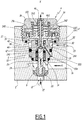
- the figure 1 represents a part of a coating product application system 2, for example a sprayer for paint, varnish, anti-corrosion coating, or any other type of product that can be envisaged.
- System 2 includes a valve 4 mounted in a bore 6 of system 2.
- the valve 4 comprises a body 8 comprising an internal central orifice 10 and a chamber 12.
- the orifice 10 and the chamber 12 are centered around a central axis X.
- the terms “axial”, “radial” , “Axially”, “radially” are used with reference to the central axis X.
- Port 10 and chamber 12 communicate fluidly.
- the orifice 10 opens out of the body 8 at the level of an end face 14 of the body 8, in the bore 6.
- System 2 includes an inlet pipe 16 for fluid in bore 6, and an outlet pipe 18 for fluid which extends from orifice 6.
- the inlet pipe and the outlet pipe can be reversed.
- the inlet duct 16 and the outlet duct 18 are mainly intended for the circulation of the coating product, but other fluids, in particular air or cleaning solvent, can also circulate in the inlet duct 16. and the outlet duct 18.
- the bore 6 comprises a seat 20, against which a needle 22 of the valve 4 cooperates so as to close or allow the circulation of the coating product of the duct. arrival 16 to the outlet duct 18, according to the arrows F1.
- the seat 20 can also be machined directly in the material of the application system 2.
- the inlet duct 16 is connected to a reservoir of coating product, not shown, or else to a pump, in particular of the “circulating” type, and the outlet duct 18 is connected to an application or spraying device, not shown, such as a gun.
- the valve 4 comprises a piston 24 formed by a rod 240 mounted in the internal orifice 10 and by a piston head 242 housed in the chamber 12.
- the rod 240 extends outside the body 8 and carries the needle 22.
- the rod 240 is intended to move in translation along the central axis X in the bore 6 in which the coating product circulates under pressure according to the arrows F1.
- the valve 4 has a first sealing device 26 housed in the body 8 around the piston rod 240 on the side of the valve 4 where the rod 240 extends outside the body 8.
- the first sealing device 26 is a seal. dynamic to prevent the infiltration of coating product between the piston rod 240 and the body 8 in the direction of the chamber 12, during the translational movements of the piston rod 240.
- the piston head 242 has an axial surface 244 perpendicular to the central axis X.
- the piston head 242 extends radially into a flange 246 in which is housed a sealing device 248, which guarantees dynamic sealing between the head of the piston.
- the sealing device 246 divides the chamber 12 into two parts 12A and 12B which are fluidly isolated from the that the seal 246 prevents the flow of fluid around the piston head 242 between part 12A and part 12B.
- Part 12A of chamber 12 is located on the side of piston rod 240.
- Axial surface 244 is located in part 12A.
- the spraying system 2 comprises an inlet pipe 28 for a pressurized control fluid, which opens into a peripheral groove 30 of the body 8.
- the peripheral groove 30 communicates with the part 12A via axial orifices 32.
- the part 12A of the chamber 12 is intended to be filled with the pressurized control fluid, for example air, so as to control the axial displacement of the piston 24.
- the valve 4 comprises a spring 34 mounted in the part 12B of the chamber 12.
- the spring 34 is centered on the central axis X and exerts an elastic force on the piston head 242 so as to drive the latter downwards, that is to say to push it into the part 12A. .
- the spring 34 bears against a part of the piston head 242 and against a plug 36 of the valve 4, which is fixed to the body 8 and screwed into the application system 2.
- the valve 4 comprises a second sealing device 38 housed in the body 8 around the piston rod 240, between the first sealing device 26 and the chamber 12.
- This sealing device 38 is a dynamic seal which prevents the air outlet of the chamber 12 during the translation of the piston rod 240, as well as the entry of other fluids into the part 12A, the pressurized control air circuit must imperatively be preserved from any fluid intrusion exterior, in particular of coating product.
- the valve 4 also comprises several static sealing devices providing a seal between the bore 6 and the body 8. These devices are formed by O-rings 39 housed in the grooves of the body 8 and which bear against the bore 6. , in particular an O-ring 39A ensuring the seal between the bore 6 and the body 8 around the end face 14.
- valve 4 comprises a vent pipe 40 allowing the product to be evacuated. of coating that has leaked to a location remote from part 12A of chamber 12.
- the vent duct 40 is provided in the piston rod 240 and communicates with the internal central orifice 10 between the first sealing device 26 and the second sealing device 38 and opens into the open air or into a part of the chamber 12 communicating with the open air.
- the vent duct 40 is formed by a duct embedded in the material forming the piston rod 240.
- the vent 40 is provided in the valve 4 itself, which does not require a vent channel in the valve. Dispensing System 2.
- the defective valve can be changed without requiring any intervention on the Dispensing System.
- the vent duct 40 is coaxial with the central axis X of the piston 24.
- the vent duct 40 comprises at least one radial orifice 42 opening into a cavity 44 of the internal central orifice 10, located axially between the first sealing device 26 and the second sealing device 38.
- a possible leakage of coating product passing through the first sealing device 26 accumulates in the cavity 44 then joins the vent pipe 40 via the radial orifices 42, according to the arrows F4.
- the vent duct 40 can comprise several radial orifices 42 distributed around the central axis X.
- the valve 4 comprises a witness 46, formed by a part integral with the piston 24 and configured to project out of the body 8 as a function of the axial position of the piston 24.
- the witness 46 is a cylindrical part coaxial with the central axis X, attached to the piston head 242, and which is inserted into a hole 360 of the stopper 36.
- vent pipe 40 is extended into a bore 460 which passes through the indicator 46, and the coating product which has leaked through the vent pipe 40 is therefore expelled into the open air according to the arrows. F4.
- a leak of coating product is therefore vented to the open air through the piston rod 240 then the indicator 46, that is to say through the components of the valve. 4, and without going through the spraying system 2. This does not require a specific vent that should be cleaned in the event of a leak.
- the coating material is directed through vent 40 away from portion 12A to prevent contamination of the control air circuit.
- the vent duct 40 may not be coaxial with the central axis X, and not pass through the witness 46 to expel the coating product in the open air.
- the vent duct can follow a path internal to the piston rod 240 and to the piston head 242 which opens into the part 12B of the chamber 12.
- the part 12B communicates with the free air via the hole 360. of the stopper 36, through which the indicator 46 slides along the central axis X. the coating product can therefore be discharged from the part 12B via the hole 360.
- a certain quantity of coating product which has leaked can accumulate around of the indicator 46 and of the spring 34, and advantageously block the valve 4 in the closed position.
- the part 12A remains protected from the leakage of coating product by the dynamic sealing device 248.
- the blocking of the valve 4 in the closed position has the effect of rapidly signaling a malfunction of the valve 4.
- the indicator 46 may also not be coaxial with the central axis X.
- the indicator 46 may also not be a separate part of the piston 24.
- the indicator and the piston 24 may be integral and form a single piece entirely crossed by the vent pipe 40 between the radial orifices 42 and the free air at the level of the plug 36.
- the valve 4 can comprise a bore 500 passing through the body 8 between the bore 6 and the cavity 44.
- the opening of the bore 500 is provided behind the seal 39A with respect to the end face 14.
- a leak between an external surface of the body 8 and the bore 6 is channeled through the bore 500 and directed towards the cavity 44, according to the arrow F5, then towards the radial ports 42 and the vent pipe 40.
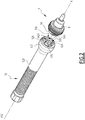
- valve 4 Another aspect of the valve 4, a tool 52 for mounting and removing the valve 4 and the operation of this tool 52 are described with reference to figures 2 to 8 .
- the valve 4 has protruding or recessed shapes on a peripheral part, configured to cooperate with protruding or recessed shapes of the tool 52. These protruding or recessed shapes are configured to transmit a rotational movement to the valve. valve 4, and to be secured to the tool 52 during disassembly of the valve 4.
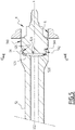
- the peripheral part is formed by a plug 54 of particular shape shown in FIG. figure 3 , and whose primary function is similar to that of the plug 36 of the figure 1 : the stopper 54 is fixed to the body 8 and screwed into the application system 2.
- the stopper 54 has for this purpose an external thread 540.
- the protruding or recessed shapes provided on the stopper 54 comprise a peripheral profile 542 and a peripheral profile 544, located behind the peripheral profile 542 with respect to an external end 546 of the valve 4 carried by an axial surface of the stopper 54.
- the peripheral profiles 542 and 544 are stepped along the X axis, the peripheral profile 542 located closest to the end 546.
- the peripheral profile 542 has three planar surfaces 542A, which extend parallel to the X axis, and form breaks in the cylindrical shape of the plug 54.
- the peripheral profile 544 includes three planar surfaces 544A aligned with the three planar surfaces 542A of the plug 54.
- the peripheral profile 544 includes three planar surfaces 544A aligned with the three planar surfaces 542A of the plug.
- peripheral profile 542, and three flat surfaces 544B angularly offset with respect to the three flat surfaces 542A.
- aligned is understood to mean that the flat surfaces 544A lie at least partially in the extension along the X axis of the flat surfaces 542A and form the same plane.
- angularly offset is meant that the surfaces 544B lie in angular sectors offset with respect to the angular sectors over which the flat surfaces 542A extend, such that the respective planes formed by the flat surfaces 542A and 544B intersect. .
- This angular offset allows the flat surfaces 544B to form shoulders axial 545 recessed relative to the peripheral profile 542. As seen in the figure 3 , the flat surfaces 544B are set back from the cylindrical part of the peripheral profile 542.
- the tool 52 comprises protruding or recessed shapes on a peripheral part, configured to cooperate with the protruding or recessed shapes provided on the stopper of the valve 4. These protruding or recessed shapes of the tool 52 are configured to transmit a rotational movement to the valve 4, and to be secured to the valve 4, during assembly or disassembly of the valve 4.
- the tool 52 extends along a central axis X52 and comprises a handle 520 and a tip 522 having a bore 524.
- the protruding or recessed shapes of the tool 52 are provided on an internal peripheral surface 524A of the bore. 524.
- the internal peripheral surface 524A has three planar peripheral surfaces 526, in number equal to the number of planar surfaces 542A of the peripheral profile 542 of the valve 4.
- the planar surfaces 526 are parallel to the axis X52 in the same manner as the surfaces 542A are parallel to the X axis.
- the peripheral surface 524A also includes a groove 528 recessed radially from the flat peripheral surfaces 526.
- the groove 528 is located behind the flat surfaces 526 with respect to a front end 530 of the tool 52
- the groove 528 forms an axial shoulder 527 configured to receive a part of the valve 4 by securing the valve 4 with the tool 52.
- the groove 528 comprises an elastic element 529 which exerts, when the valve 4 is received in the tool 52, an elastic force oriented along the axis X52 against the part of the valve 4 received in the groove 528.
- This elastic element 529 can be for example an O-ring. In a variant not shown, this elastic element can also be a spiral spring or a spring washer (Belleville washer).
- the peripheral profile 542 can comprise a different number of flat surfaces, more generally at least one flat surface.
- the peripheral profile 544 may have a number of flat surfaces aligned with the flat surfaces of the peripheral profile 542 other than three, more generally at least one, and at least one flat surface angularly offset with respect to the flat surface (s) of the device.
- the tool 52 may have a number of flat surfaces 526 other than three, more generally at least one flat surface.
- valve 4 The operation of the tool 52 with the valve 4 is described below.
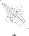
- the figures 4 , 5 and 6 show the assembly of the valve 4 in its housing. Valve 4 is positioned in its bore 6, then the tool 52 is approached to the valve 4 so that the axes X and X52 coincide ( figure 4 ).
- the peripheral profile 542 is found blocked in the groove 528 by the insertion of the flat surfaces 526 of the tool 52 in the recessed reliefs formed by the peripheral profile 544.
- the shoulders 527 of the tool 52 s' then axially oppose the shoulders 545 of the valve 4 and prevent the withdrawal of the tool 52 from the valve 4.
- the elastic force exerted by the elastic element 529 tends to push the valve 4 out of the bore 544 and therefore locks the valve. contact between the shoulders 527 and 545.
- the valve 4 and the tool 52 then form an integral assembly.
- the valve 4 and the tool 52 form a "bayonet" assembly.
- the operator exerts a plane contact between the surfaces 526 and 544B which makes it possible to unscrew the valve 4.
- the valve 4 can be easily extracted, even when 'a location difficult to access, because the valve 4 remains attached to the tip 522 of the tool 52.
- the valve 4 remains integral with the tool 52 and does not risk falling.
- This possibility of hooking the valve 4 to the end piece 522 can also be used when mounting the valve 4 in a location that is difficult to access.
- the operator can fix the valve 4 to the tool 52 prior to assembly, by inserting it into the bore 524 and then by turning it in the unscrewing direction. After having mounted the valve 4 in its bore 6, the operator then turns the tool 52 in the direction of screwing. The valve 4 will then turn freely and screw in until the screwing is done with resistance. The torque of the tool 52 then overcomes the force exerted by the elastic element and the tool 52 rotates relative to the valve 4 until the surfaces 526 cooperate with the surfaces 542A and 544A. Screwing can then be continued until locking.
- the tool 52 and the recessed / protruding reliefs provided on the valve 4 therefore make it possible to use the same tool for mounting and removing the valve.
- the means allowing assembly and disassembly being both provided on a single tip 522 of the tool 52, it is not necessary to turn it to perform one or the other operation.
- the possibility of securing the valve 4 and the tool 52 by a bayonet mounting makes it possible to easily mount or dismantle the valve 4 in locations that are difficult to access.
- the unscrewing of the valve and its extraction can in particular be carried out in a single operation, unlike the known techniques in which the unscrewing and the extraction are carried out with two different tools which sometimes require tedious exchanges if the valve is not sufficiently unscrewed.
Landscapes
- Engineering & Computer Science (AREA)
- General Engineering & Computer Science (AREA)
- Mechanical Engineering (AREA)
- Lift Valve (AREA)
- Valve Housings (AREA)
- Fluid-Driven Valves (AREA)
- Spray Control Apparatus (AREA)
- Details Or Accessories Of Spraying Plant Or Apparatus (AREA)
- Nozzles (AREA)
Applications Claiming Priority (1)
| Application Number | Priority Date | Filing Date | Title |
|---|---|---|---|
| FR1909623A FR3100302B1 (fr) | 2019-09-02 | 2019-09-02 | Vanne, système d’application de produit de revêtement comprenant une telle vanne |
Publications (2)
| Publication Number | Publication Date |
|---|---|
| EP3785802A1 true EP3785802A1 (de) | 2021-03-03 |
| EP3785802B1 EP3785802B1 (de) | 2022-03-16 |
Family
ID=68211099
Family Applications (2)
| Application Number | Title | Priority Date | Filing Date |
|---|---|---|---|
| EP20193810.7A Active EP3785802B1 (de) | 2019-09-02 | 2020-09-01 | Ventil, system zur auftragung eines beschichtungsprodukts, das ein solches ventil umfasst, und werkzeug für dessen montage und demontage |
| EP20193822.2A Active EP3785803B1 (de) | 2019-09-02 | 2020-09-01 | Ventil und system zur auftragung eines beschichtungsprodukts, das ein solches ventil umfasst |
Family Applications After (1)
| Application Number | Title | Priority Date | Filing Date |
|---|---|---|---|
| EP20193822.2A Active EP3785803B1 (de) | 2019-09-02 | 2020-09-01 | Ventil und system zur auftragung eines beschichtungsprodukts, das ein solches ventil umfasst |
Country Status (7)
| Country | Link |
|---|---|
| US (2) | US11396029B2 (de) |
| EP (2) | EP3785802B1 (de) |
| JP (2) | JP7497252B2 (de) |
| KR (2) | KR102880098B1 (de) |
| CN (2) | CN112443702B (de) |
| ES (2) | ES2911507T3 (de) |
| RU (2) | RU2020128755A (de) |
Cited By (1)
| Publication number | Priority date | Publication date | Assignee | Title |
|---|---|---|---|---|
| EP4439031A1 (de) * | 2023-03-28 | 2024-10-02 | Exel Industries | Anzeiger zur anzeige der überbelegung eines unter druck stehenden flüssigkeitslecks in einer entlüftungskammer eines druckflüssigkeitsgeräts |
Families Citing this family (5)
| Publication number | Priority date | Publication date | Assignee | Title |
|---|---|---|---|---|
| DE102015010158A1 (de) * | 2015-07-03 | 2017-01-05 | Dürr Systems Ag | Applikationsgerät, insbesondere Rotationszerstäuber |
| EP3899337A1 (de) * | 2018-12-21 | 2021-10-27 | ABB Schweiz AG | Ventil |
| CN219680868U (zh) * | 2023-01-19 | 2023-09-15 | 上海埃尔翡生命科技有限公司 | 一种肩关节植入物 |
| CN115949757A (zh) * | 2023-01-31 | 2023-04-11 | 天津铭捷智能装备有限公司 | 一种固化剂微动阀 |
| DE102024103737A1 (de) * | 2024-02-09 | 2025-08-14 | Delo Industrie Klebstoffe Gmbh & Co. Kgaa | Dosiervorrichtung sowie Verfahren zum Dosieren von Fluiden |
Citations (6)
| Publication number | Priority date | Publication date | Assignee | Title |
|---|---|---|---|---|
| FR2416057A1 (fr) * | 1978-02-06 | 1979-08-31 | Elson James | Appareil distributeur de liquide sous forme de jet, de jet de liquide pulverise, ou d'aerosol |
| WO1990008267A1 (fr) * | 1989-01-10 | 1990-07-26 | Thiffault Jean Claude | Conception d'encoches qui s'enclenchent et s'interbarrent ensemble, applicable a tous objets tournables |
| US20040099103A1 (en) * | 2002-11-21 | 2004-05-27 | Vaughan Billy S. | Adaptive socket tool |
| WO2008001393A1 (en) * | 2006-06-27 | 2008-01-03 | Fiskvelar Ehf. | Safety wrench and a matching nut |
| WO2010029633A1 (ja) * | 2008-09-11 | 2010-03-18 | 光洋器材株式会社 | 脱落防止締結具 |
| WO2015063295A1 (fr) * | 2013-11-04 | 2015-05-07 | Sames Technologies | Dispositif d'alimentation d'un projecteur en produit de revetement liquide |
Family Cites Families (21)
| Publication number | Priority date | Publication date | Assignee | Title |
|---|---|---|---|---|
| US2888033A (en) * | 1954-06-18 | 1959-05-26 | Henry C Eickmeyer | Constant pressure outlet valve |
| US3831858A (en) * | 1973-03-01 | 1974-08-27 | Us Navy | Vented plunger atomizer |
| DE2623039C3 (de) | 1976-05-22 | 1980-11-13 | Leonhard Schleicher Suedmo-Armaturenfabrik Gmbh, 7081 Riesbuerg | Absperrventil mit Leckagesicherung |
| US4162763A (en) * | 1978-01-10 | 1979-07-31 | Camsco, Inc. | Water jet valve assembly |
| DE3005329C2 (de) | 1980-02-13 | 1985-08-22 | Leonhard Schleicher Südmo-Armaturenfabrik GmbH, 7081 Riesbürg | Absperrventil mit Leckagesicherung |
| JPH0325477Y2 (de) * | 1986-05-20 | 1991-06-03 | ||
| US5296035A (en) * | 1992-03-27 | 1994-03-22 | Nordson Corporation | Apparatus and method for applying coating material |
| US6827299B2 (en) * | 2003-01-24 | 2004-12-07 | Spraying Systems Co. | Gang mountable spray gun |
| FR2863512B1 (fr) * | 2003-12-10 | 2006-01-21 | Itw Surfaces & Finitions | Pistolet automatique de pulverisation |
| US7021565B2 (en) * | 2004-02-10 | 2006-04-04 | Caterpillar Inc. | Pressure modulated common rail injector and system |
| JP5075858B2 (ja) * | 2009-03-06 | 2012-11-21 | 八千代工業株式会社 | 塗料用バルブの作動不良検出方法 |
| JP5308197B2 (ja) | 2009-03-06 | 2013-10-09 | 八千代工業株式会社 | 塗料用バルブの塗料漏れ検出装置 |
| US8875650B2 (en) * | 2011-10-12 | 2014-11-04 | Toyota Motor Engineering & Manufacturing North America, Inc. | Valve assemblies including valve seat assemblies |
| DE102012217683B3 (de) * | 2012-09-27 | 2014-02-20 | Volkswagen Varta Microbattery Forschungsgesellschaft Mbh & Co. Kg | Schaltbares Schlitzventil für eine Beschichtungsanlage, Beschichtungsanlage und Verwendung der Anlage |
| FR3012864B1 (fr) * | 2013-11-04 | 2017-03-31 | Sames Tech | Dispositif d'alimentation d'un projecteur en produit de revetement liquide et outil de montage/demontage d'un tel dispositif |
| FR3012863B1 (fr) * | 2013-11-04 | 2017-04-07 | Sames Tech | Dispositif d'alimentation d'un projecteur en produit de revetement liquide |
| CN104259055A (zh) | 2014-09-12 | 2015-01-07 | 大连华工创新科技股份有限公司 | 针阀胶阀 |
| TWI692373B (zh) * | 2015-01-26 | 2020-05-01 | 德商碧然德有限公司 | 用於液體處理系統的閥、閥致動裝置、芯和適配器 |
| US9816849B2 (en) * | 2015-05-22 | 2017-11-14 | Nordson Corporation | Dispensing apparatus and methods utilizing quick connect member to secure fluid body and actuator body |
| GB2540439A (en) * | 2015-07-17 | 2017-01-18 | Alternative Packaging Solutions Llc | A pump mechanism for a spray dispenser |
| US9822897B2 (en) | 2016-03-18 | 2017-11-21 | Matthew Gross | One-way valve cap |
-
2020
- 2020-08-28 JP JP2020144641A patent/JP7497252B2/ja active Active
- 2020-08-28 CN CN202010885040.4A patent/CN112443702B/zh active Active
- 2020-08-31 RU RU2020128755A patent/RU2020128755A/ru unknown
- 2020-08-31 US US17/007,222 patent/US11396029B2/en active Active
- 2020-08-31 US US17/007,336 patent/US11383261B2/en active Active
- 2020-08-31 JP JP2020145587A patent/JP7575219B2/ja active Active
- 2020-08-31 RU RU2020128759A patent/RU2020128759A/ru unknown
- 2020-09-01 ES ES20193810T patent/ES2911507T3/es active Active
- 2020-09-01 CN CN202010904840.6A patent/CN112439641B/zh active Active
- 2020-09-01 EP EP20193810.7A patent/EP3785802B1/de active Active
- 2020-09-01 KR KR1020200111183A patent/KR102880098B1/ko active Active
- 2020-09-01 ES ES20193822T patent/ES2911497T3/es active Active
- 2020-09-01 EP EP20193822.2A patent/EP3785803B1/de active Active
- 2020-09-01 KR KR1020200111030A patent/KR102880095B1/ko active Active
Patent Citations (6)
| Publication number | Priority date | Publication date | Assignee | Title |
|---|---|---|---|---|
| FR2416057A1 (fr) * | 1978-02-06 | 1979-08-31 | Elson James | Appareil distributeur de liquide sous forme de jet, de jet de liquide pulverise, ou d'aerosol |
| WO1990008267A1 (fr) * | 1989-01-10 | 1990-07-26 | Thiffault Jean Claude | Conception d'encoches qui s'enclenchent et s'interbarrent ensemble, applicable a tous objets tournables |
| US20040099103A1 (en) * | 2002-11-21 | 2004-05-27 | Vaughan Billy S. | Adaptive socket tool |
| WO2008001393A1 (en) * | 2006-06-27 | 2008-01-03 | Fiskvelar Ehf. | Safety wrench and a matching nut |
| WO2010029633A1 (ja) * | 2008-09-11 | 2010-03-18 | 光洋器材株式会社 | 脱落防止締結具 |
| WO2015063295A1 (fr) * | 2013-11-04 | 2015-05-07 | Sames Technologies | Dispositif d'alimentation d'un projecteur en produit de revetement liquide |
Cited By (2)
| Publication number | Priority date | Publication date | Assignee | Title |
|---|---|---|---|---|
| EP4439031A1 (de) * | 2023-03-28 | 2024-10-02 | Exel Industries | Anzeiger zur anzeige der überbelegung eines unter druck stehenden flüssigkeitslecks in einer entlüftungskammer eines druckflüssigkeitsgeräts |
| FR3147368A1 (fr) * | 2023-03-28 | 2024-10-04 | Exel Industries | Indicateur pour indiquer la survenance d’une fuite de fluide pressurisé dans une chambre d’évent d’un appareil à fluide pressurisé |
Also Published As
| Publication number | Publication date |
|---|---|
| KR102880098B1 (ko) | 2025-11-03 |
| EP3785802B1 (de) | 2022-03-16 |
| RU2020128755A (ru) | 2022-02-28 |
| CN112439641A (zh) | 2021-03-05 |
| US11396029B2 (en) | 2022-07-26 |
| EP3785803B1 (de) | 2022-03-16 |
| CN112443702B (zh) | 2025-05-27 |
| JP2021038846A (ja) | 2021-03-11 |
| JP2021038847A (ja) | 2021-03-11 |
| US20210060599A1 (en) | 2021-03-04 |
| CN112439641B (zh) | 2023-09-08 |
| US20210060586A1 (en) | 2021-03-04 |
| US11383261B2 (en) | 2022-07-12 |
| EP3785803A1 (de) | 2021-03-03 |
| KR102880095B1 (ko) | 2025-11-03 |
| KR20210027217A (ko) | 2021-03-10 |
| ES2911507T3 (es) | 2022-05-19 |
| RU2020128759A (ru) | 2022-03-03 |
| KR20210027216A (ko) | 2021-03-10 |
| JP7575219B2 (ja) | 2024-10-29 |
| ES2911497T3 (es) | 2022-05-19 |
| JP7497252B2 (ja) | 2024-06-10 |
| CN112443702A (zh) | 2021-03-05 |
Similar Documents
| Publication | Publication Date | Title |
|---|---|---|
| EP3785802B1 (de) | Ventil, system zur auftragung eines beschichtungsprodukts, das ein solches ventil umfasst, und werkzeug für dessen montage und demontage | |
| EP0375533B2 (de) | Molchfähige Flüssigkeitsverteilungsleitung mit molchfähigem 3-Wege-Ventil | |
| FR2638502A1 (fr) | Vanne a disques pour permettre ou non le passage du fluide | |
| FR3105938A1 (fr) | Vanne, système d’application de produit de revêtement comprenant une telle vanne et outil dédié de montage et démontage | |
| WO2006120326A1 (fr) | Cartouche filtrante et systeme de montage d'une telle cartouche avec des moyens de detrompage | |
| FR2901340A1 (fr) | Agencement de distributeur hydraulique sous forme de cartouche | |
| EP0268521B1 (de) | Schleusenventil | |
| WO2021094690A1 (fr) | Clapet à piston compact | |
| EP3146172A1 (de) | Flüssigkeitstransfervorrichtung | |
| FR2492022A1 (fr) | Dispositif d'accouplement rigide monte sous pression de fluide | |
| EP2129946B1 (de) | Einheitlicher kugelförmiger hahn mit verschlussstopfen | |
| FR2638503A1 (fr) | Vanne a disques a manchon de decharge amovible pour l'ecoulement d'un fluide | |
| WO2000077438A1 (fr) | Embout femelle et raccord de conduit comportant ledit embout femelle | |
| EP0785344B1 (de) | Aufsteckbare Kühlungsöldüse | |
| FR2704293A1 (fr) | Robinet à tournant cylindrique. | |
| EP0859178B1 (de) | Durchflussregelndes Schieberventil | |
| WO2005100188A2 (fr) | Dispositif de distribution de produits a obturateur rotatif | |
| EP3719608B1 (de) | Mischeinheit und mischbatterie, die eine solche mischeinheit umfasst | |
| EP1946050B1 (de) | Zylindrische messkammer eines wassermessers | |
| WO2017064298A1 (fr) | Bouchon de carter et coupleur pour ouvrir ledit bouchon | |
| EP3572635B1 (de) | Vorrichtung zum ablassen von flüssigkeit für flüssigkeitsbehälter | |
| EP3775645B1 (de) | Verbessertes regelventil mit integrierter spülfunktion | |
| EP3406901B1 (de) | Hydraulisches gerät, das einen verbesserten verteiler umfasst | |
| EP0328433A1 (de) | Gleitringdichtung | |
| FR2867546A1 (fr) | Raccord a vis pour tubes ou tuyaux. |
Legal Events
| Date | Code | Title | Description |
|---|---|---|---|
| PUAI | Public reference made under article 153(3) epc to a published international application that has entered the european phase |
Free format text: ORIGINAL CODE: 0009012 |
|
| STAA | Information on the status of an ep patent application or granted ep patent |
Free format text: STATUS: THE APPLICATION HAS BEEN PUBLISHED |
|
| AK | Designated contracting states |
Kind code of ref document: A1 Designated state(s): AL AT BE BG CH CY CZ DE DK EE ES FI FR GB GR HR HU IE IS IT LI LT LU LV MC MK MT NL NO PL PT RO RS SE SI SK SM TR |
|
| AX | Request for extension of the european patent |
Extension state: BA ME |
|
| STAA | Information on the status of an ep patent application or granted ep patent |
Free format text: STATUS: REQUEST FOR EXAMINATION WAS MADE |
|
| 17P | Request for examination filed |
Effective date: 20210804 |
|
| RBV | Designated contracting states (corrected) |
Designated state(s): AL AT BE BG CH CY CZ DE DK EE ES FI FR GB GR HR HU IE IS IT LI LT LU LV MC MK MT NL NO PL PT RO RS SE SI SK SM TR |
|
| GRAP | Despatch of communication of intention to grant a patent |
Free format text: ORIGINAL CODE: EPIDOSNIGR1 |
|
| STAA | Information on the status of an ep patent application or granted ep patent |
Free format text: STATUS: GRANT OF PATENT IS INTENDED |
|
| RIC1 | Information provided on ipc code assigned before grant |
Ipc: B25B 23/10 20060101ALI20211123BHEP Ipc: B25B 13/06 20060101ALI20211123BHEP Ipc: F16K 51/00 20060101ALI20211123BHEP Ipc: F16K 31/46 20060101ALI20211123BHEP Ipc: F16K 31/122 20060101ALI20211123BHEP Ipc: B05B 1/30 20060101AFI20211123BHEP |
|
| INTG | Intention to grant announced |
Effective date: 20211216 |
|
| GRAS | Grant fee paid |
Free format text: ORIGINAL CODE: EPIDOSNIGR3 |
|
| GRAA | (expected) grant |
Free format text: ORIGINAL CODE: 0009210 |
|
| STAA | Information on the status of an ep patent application or granted ep patent |
Free format text: STATUS: THE PATENT HAS BEEN GRANTED |
|
| AK | Designated contracting states |
Kind code of ref document: B1 Designated state(s): AL AT BE BG CH CY CZ DE DK EE ES FI FR GB GR HR HU IE IS IT LI LT LU LV MC MK MT NL NO PL PT RO RS SE SI SK SM TR |
|
| REG | Reference to a national code |
Ref country code: GB Ref legal event code: FG4D Free format text: NOT ENGLISH |
|
| REG | Reference to a national code |
Ref country code: CH Ref legal event code: EP Ref country code: DE Ref legal event code: R096 Ref document number: 602020002239 Country of ref document: DE |
|
| REG | Reference to a national code |
Ref country code: IE Ref legal event code: FG4D Free format text: LANGUAGE OF EP DOCUMENT: FRENCH |
|
| REG | Reference to a national code |
Ref country code: AT Ref legal event code: REF Ref document number: 1475500 Country of ref document: AT Kind code of ref document: T Effective date: 20220415 |
|
| REG | Reference to a national code |
Ref country code: ES Ref legal event code: FG2A Ref document number: 2911507 Country of ref document: ES Kind code of ref document: T3 Effective date: 20220519 |
|
| REG | Reference to a national code |
Ref country code: LT Ref legal event code: MG9D |
|
| REG | Reference to a national code |
Ref country code: NL Ref legal event code: MP Effective date: 20220316 |
|
| PG25 | Lapsed in a contracting state [announced via postgrant information from national office to epo] |
Ref country code: SE Free format text: LAPSE BECAUSE OF FAILURE TO SUBMIT A TRANSLATION OF THE DESCRIPTION OR TO PAY THE FEE WITHIN THE PRESCRIBED TIME-LIMIT Effective date: 20220316 Ref country code: RS Free format text: LAPSE BECAUSE OF FAILURE TO SUBMIT A TRANSLATION OF THE DESCRIPTION OR TO PAY THE FEE WITHIN THE PRESCRIBED TIME-LIMIT Effective date: 20220316 Ref country code: NO Free format text: LAPSE BECAUSE OF FAILURE TO SUBMIT A TRANSLATION OF THE DESCRIPTION OR TO PAY THE FEE WITHIN THE PRESCRIBED TIME-LIMIT Effective date: 20220616 Ref country code: LT Free format text: LAPSE BECAUSE OF FAILURE TO SUBMIT A TRANSLATION OF THE DESCRIPTION OR TO PAY THE FEE WITHIN THE PRESCRIBED TIME-LIMIT Effective date: 20220316 Ref country code: HR Free format text: LAPSE BECAUSE OF FAILURE TO SUBMIT A TRANSLATION OF THE DESCRIPTION OR TO PAY THE FEE WITHIN THE PRESCRIBED TIME-LIMIT Effective date: 20220316 Ref country code: BG Free format text: LAPSE BECAUSE OF FAILURE TO SUBMIT A TRANSLATION OF THE DESCRIPTION OR TO PAY THE FEE WITHIN THE PRESCRIBED TIME-LIMIT Effective date: 20220616 |
|
| REG | Reference to a national code |
Ref country code: AT Ref legal event code: MK05 Ref document number: 1475500 Country of ref document: AT Kind code of ref document: T Effective date: 20220316 |
|
| PG25 | Lapsed in a contracting state [announced via postgrant information from national office to epo] |
Ref country code: LV Free format text: LAPSE BECAUSE OF FAILURE TO SUBMIT A TRANSLATION OF THE DESCRIPTION OR TO PAY THE FEE WITHIN THE PRESCRIBED TIME-LIMIT Effective date: 20220316 Ref country code: GR Free format text: LAPSE BECAUSE OF FAILURE TO SUBMIT A TRANSLATION OF THE DESCRIPTION OR TO PAY THE FEE WITHIN THE PRESCRIBED TIME-LIMIT Effective date: 20220617 Ref country code: FI Free format text: LAPSE BECAUSE OF FAILURE TO SUBMIT A TRANSLATION OF THE DESCRIPTION OR TO PAY THE FEE WITHIN THE PRESCRIBED TIME-LIMIT Effective date: 20220316 |
|
| PG25 | Lapsed in a contracting state [announced via postgrant information from national office to epo] |
Ref country code: NL Free format text: LAPSE BECAUSE OF FAILURE TO SUBMIT A TRANSLATION OF THE DESCRIPTION OR TO PAY THE FEE WITHIN THE PRESCRIBED TIME-LIMIT Effective date: 20220316 |
|
| PG25 | Lapsed in a contracting state [announced via postgrant information from national office to epo] |
Ref country code: SM Free format text: LAPSE BECAUSE OF FAILURE TO SUBMIT A TRANSLATION OF THE DESCRIPTION OR TO PAY THE FEE WITHIN THE PRESCRIBED TIME-LIMIT Effective date: 20220316 Ref country code: SK Free format text: LAPSE BECAUSE OF FAILURE TO SUBMIT A TRANSLATION OF THE DESCRIPTION OR TO PAY THE FEE WITHIN THE PRESCRIBED TIME-LIMIT Effective date: 20220316 Ref country code: RO Free format text: LAPSE BECAUSE OF FAILURE TO SUBMIT A TRANSLATION OF THE DESCRIPTION OR TO PAY THE FEE WITHIN THE PRESCRIBED TIME-LIMIT Effective date: 20220316 Ref country code: PT Free format text: LAPSE BECAUSE OF FAILURE TO SUBMIT A TRANSLATION OF THE DESCRIPTION OR TO PAY THE FEE WITHIN THE PRESCRIBED TIME-LIMIT Effective date: 20220718 Ref country code: EE Free format text: LAPSE BECAUSE OF FAILURE TO SUBMIT A TRANSLATION OF THE DESCRIPTION OR TO PAY THE FEE WITHIN THE PRESCRIBED TIME-LIMIT Effective date: 20220316 Ref country code: CZ Free format text: LAPSE BECAUSE OF FAILURE TO SUBMIT A TRANSLATION OF THE DESCRIPTION OR TO PAY THE FEE WITHIN THE PRESCRIBED TIME-LIMIT Effective date: 20220316 Ref country code: AT Free format text: LAPSE BECAUSE OF FAILURE TO SUBMIT A TRANSLATION OF THE DESCRIPTION OR TO PAY THE FEE WITHIN THE PRESCRIBED TIME-LIMIT Effective date: 20220316 |
|
| PG25 | Lapsed in a contracting state [announced via postgrant information from national office to epo] |
Ref country code: PL Free format text: LAPSE BECAUSE OF FAILURE TO SUBMIT A TRANSLATION OF THE DESCRIPTION OR TO PAY THE FEE WITHIN THE PRESCRIBED TIME-LIMIT Effective date: 20220316 Ref country code: IS Free format text: LAPSE BECAUSE OF FAILURE TO SUBMIT A TRANSLATION OF THE DESCRIPTION OR TO PAY THE FEE WITHIN THE PRESCRIBED TIME-LIMIT Effective date: 20220716 Ref country code: AL Free format text: LAPSE BECAUSE OF FAILURE TO SUBMIT A TRANSLATION OF THE DESCRIPTION OR TO PAY THE FEE WITHIN THE PRESCRIBED TIME-LIMIT Effective date: 20220316 |
|
| REG | Reference to a national code |
Ref country code: DE Ref legal event code: R097 Ref document number: 602020002239 Country of ref document: DE |
|
| PLBE | No opposition filed within time limit |
Free format text: ORIGINAL CODE: 0009261 |
|
| STAA | Information on the status of an ep patent application or granted ep patent |
Free format text: STATUS: NO OPPOSITION FILED WITHIN TIME LIMIT |
|
| PG25 | Lapsed in a contracting state [announced via postgrant information from national office to epo] |
Ref country code: DK Free format text: LAPSE BECAUSE OF FAILURE TO SUBMIT A TRANSLATION OF THE DESCRIPTION OR TO PAY THE FEE WITHIN THE PRESCRIBED TIME-LIMIT Effective date: 20220316 |
|
| 26N | No opposition filed |
Effective date: 20221219 |
|
| PG25 | Lapsed in a contracting state [announced via postgrant information from national office to epo] |
Ref country code: SI Free format text: LAPSE BECAUSE OF FAILURE TO SUBMIT A TRANSLATION OF THE DESCRIPTION OR TO PAY THE FEE WITHIN THE PRESCRIBED TIME-LIMIT Effective date: 20220316 |
|
| PG25 | Lapsed in a contracting state [announced via postgrant information from national office to epo] |
Ref country code: MC Free format text: LAPSE BECAUSE OF FAILURE TO SUBMIT A TRANSLATION OF THE DESCRIPTION OR TO PAY THE FEE WITHIN THE PRESCRIBED TIME-LIMIT Effective date: 20220316 |
|
| REG | Reference to a national code |
Ref country code: BE Ref legal event code: MM Effective date: 20220930 |
|
| PG25 | Lapsed in a contracting state [announced via postgrant information from national office to epo] |
Ref country code: LU Free format text: LAPSE BECAUSE OF NON-PAYMENT OF DUE FEES Effective date: 20220901 |
|
| PG25 | Lapsed in a contracting state [announced via postgrant information from national office to epo] |
Ref country code: IE Free format text: LAPSE BECAUSE OF NON-PAYMENT OF DUE FEES Effective date: 20220901 |
|
| PG25 | Lapsed in a contracting state [announced via postgrant information from national office to epo] |
Ref country code: BE Free format text: LAPSE BECAUSE OF NON-PAYMENT OF DUE FEES Effective date: 20220930 |
|
| PG25 | Lapsed in a contracting state [announced via postgrant information from national office to epo] |
Ref country code: CY Free format text: LAPSE BECAUSE OF FAILURE TO SUBMIT A TRANSLATION OF THE DESCRIPTION OR TO PAY THE FEE WITHIN THE PRESCRIBED TIME-LIMIT Effective date: 20220316 |
|
| PG25 | Lapsed in a contracting state [announced via postgrant information from national office to epo] |
Ref country code: MK Free format text: LAPSE BECAUSE OF FAILURE TO SUBMIT A TRANSLATION OF THE DESCRIPTION OR TO PAY THE FEE WITHIN THE PRESCRIBED TIME-LIMIT Effective date: 20220316 Ref country code: HU Free format text: LAPSE BECAUSE OF FAILURE TO SUBMIT A TRANSLATION OF THE DESCRIPTION OR TO PAY THE FEE WITHIN THE PRESCRIBED TIME-LIMIT; INVALID AB INITIO Effective date: 20200901 |
|
| PG25 | Lapsed in a contracting state [announced via postgrant information from national office to epo] |
Ref country code: MT Free format text: LAPSE BECAUSE OF FAILURE TO SUBMIT A TRANSLATION OF THE DESCRIPTION OR TO PAY THE FEE WITHIN THE PRESCRIBED TIME-LIMIT Effective date: 20220316 |
|
| REG | Reference to a national code |
Ref country code: CH Ref legal event code: U11 Free format text: ST27 STATUS EVENT CODE: U-0-0-U10-U11 (AS PROVIDED BY THE NATIONAL OFFICE) Effective date: 20251001 |
|
| PGFP | Annual fee paid to national office [announced via postgrant information from national office to epo] |
Ref country code: DE Payment date: 20250916 Year of fee payment: 6 |
|
| PGFP | Annual fee paid to national office [announced via postgrant information from national office to epo] |
Ref country code: TR Payment date: 20250829 Year of fee payment: 6 Ref country code: IT Payment date: 20250909 Year of fee payment: 6 |
|
| PGFP | Annual fee paid to national office [announced via postgrant information from national office to epo] |
Ref country code: GB Payment date: 20250919 Year of fee payment: 6 |
|
| PGFP | Annual fee paid to national office [announced via postgrant information from national office to epo] |
Ref country code: FR Payment date: 20250929 Year of fee payment: 6 |
|
| REG | Reference to a national code |
Ref country code: CH Ref legal event code: R18 Free format text: ST27 STATUS EVENT CODE: U-0-0-R10-R18 (AS PROVIDED BY THE NATIONAL OFFICE) Effective date: 20260106 |
|
| PGFP | Annual fee paid to national office [announced via postgrant information from national office to epo] |
Ref country code: CH Payment date: 20251001 Year of fee payment: 6 |
|
| PGFP | Annual fee paid to national office [announced via postgrant information from national office to epo] |
Ref country code: ES Payment date: 20251015 Year of fee payment: 6 |