EP3786055A1 - Système et procédé de conditionnement d'air de cabine - Google Patents
Système et procédé de conditionnement d'air de cabine Download PDFInfo
- Publication number
- EP3786055A1 EP3786055A1 EP19194911.4A EP19194911A EP3786055A1 EP 3786055 A1 EP3786055 A1 EP 3786055A1 EP 19194911 A EP19194911 A EP 19194911A EP 3786055 A1 EP3786055 A1 EP 3786055A1
- Authority
- EP
- European Patent Office
- Prior art keywords
- cabin
- air conditioning
- air
- hatch
- conditioning system
- Prior art date
- Legal status (The legal status is an assumption and is not a legal conclusion. Google has not performed a legal analysis and makes no representation as to the accuracy of the status listed.)
- Granted
Links
Images


Classifications
-
- F—MECHANICAL ENGINEERING; LIGHTING; HEATING; WEAPONS; BLASTING
- F24—HEATING; RANGES; VENTILATING
- F24F—AIR-CONDITIONING; AIR-HUMIDIFICATION; VENTILATION; USE OF AIR CURRENTS FOR SCREENING
- F24F11/00—Control or safety arrangements
- F24F11/70—Control systems characterised by their outputs; Constructional details thereof
- F24F11/80—Control systems characterised by their outputs; Constructional details thereof for controlling the temperature of the supplied air
- F24F11/83—Control systems characterised by their outputs; Constructional details thereof for controlling the temperature of the supplied air by controlling the supply of heat-exchange fluids to heat-exchangers
-
- B—PERFORMING OPERATIONS; TRANSPORTING
- B63—SHIPS OR OTHER WATERBORNE VESSELS; RELATED EQUIPMENT
- B63J—AUXILIARIES ON VESSELS
- B63J2/00—Arrangements of ventilation, heating, cooling, or air-conditioning
- B63J2/02—Ventilation; Air-conditioning
- B63J2/04—Ventilation; Air-conditioning of living spaces
-
- F—MECHANICAL ENGINEERING; LIGHTING; HEATING; WEAPONS; BLASTING
- F24—HEATING; RANGES; VENTILATING
- F24F—AIR-CONDITIONING; AIR-HUMIDIFICATION; VENTILATION; USE OF AIR CURRENTS FOR SCREENING
- F24F13/00—Details common to, or for air-conditioning, air-humidification, ventilation or use of air currents for screening
- F24F13/22—Means for preventing condensation or evacuating condensate
-
- F—MECHANICAL ENGINEERING; LIGHTING; HEATING; WEAPONS; BLASTING
- F24—HEATING; RANGES; VENTILATING
- F24F—AIR-CONDITIONING; AIR-HUMIDIFICATION; VENTILATION; USE OF AIR CURRENTS FOR SCREENING
- F24F13/00—Details common to, or for air-conditioning, air-humidification, ventilation or use of air currents for screening
- F24F13/22—Means for preventing condensation or evacuating condensate
- F24F2013/221—Means for preventing condensation or evacuating condensate to avoid the formation of condensate, e.g. dew
-
- F—MECHANICAL ENGINEERING; LIGHTING; HEATING; WEAPONS; BLASTING
- F24—HEATING; RANGES; VENTILATING
- F24F—AIR-CONDITIONING; AIR-HUMIDIFICATION; VENTILATION; USE OF AIR CURRENTS FOR SCREENING
- F24F2221/00—Details or features not otherwise provided for
- F24F2221/34—Heater, e.g. gas burner, electric air heater
Definitions
- the present invention relates to a system and a method for air conditioning a cabin of a ship.
- cruise ships have high expectations for the trip.
- the cabin environment must be comfortable so that the travelers enjoy their time in the cabins.
- cruise ships are used in variable conditions like cold, windy, warm and moist.
- the variable conditions set demanding requirements for the air conditioning systems of the cabins.
- the chilled beam comprises a heat exchanger in which a heat exchange fluid, e.g. refrigerant, is circulated.
- the heat exchange fluid is cooled, for example with another heat exchanger outside the chilled beam, before entering inside the chilled beam and the heat exchanger inside the chilled beam, and the cabin air is cooled when it is circulated from cabin into the chilled beam and through the heat exchanger inside the chilled beam.
- the condensation is handled for example by collecting the condensed water into a separate container, in which it is converted into vapour or sewered. This may cause problems in the chilled beam where the circulating cabin air is not filtered and the dust in the cabin air is collected to the wet coil surfaces. Eventually the collected dust may clog the heat exchanger in the chilled beam.
- the objective of the device/method is to alleviate the disadvantages mentioned above.
- the present invention provides a cabin conditioning system for air conditioning cabin space.
- the system comprises an air conditioning device for cooling the cabin temperature, and a control unit for controlling the cabin conditioning system.
- the system further comprises a first sensor arranged to send signals to the control unit if a hatch to the outdoor is opened or closed, a control valve for controlling the cooling medium flow to the air conditioning device, a water heater for heating the cooling medium before entering the air conditioning device, and the first sensor is arranged to send a first signal to the control unit, when the hatch is opened, wherein the control unit is arranged to switch on the water heater, for heating the cooling medium.
- the advantage of the system is that it prevents condensation within an air conditioning device in a cabin if a sudden burst of warm and/or moist air is entered inside the cabin, e.g. when a balcony door or a window is opened. Further, the system does not require any channels or piping for the water caused by condensation inside the air conditioning device.
- control unit is arranged to close the control valve, when the hatch is opened, and open the control valve, when the hatch is closed.
- the senor is arranged to send a second signal to the control unit, when the hatch is closed, wherein the control unit is arranged to switch off the water heater.
- the hatch is a door.
- the hatch is a window.
- the system comprises plurality of sensors for measuring at least one air characteristic inside the cabin space.
- the water heater is an electric heater.
- the system comprises a user interface provided inside the cabin for controlling the air conditioning system.
- the air conditioning device is a chilled beam.
- the air conditioning device is a fan-coil unit.
- the air conditioning device is a cooling panel.
- control unit is arranged to switch off the water heater when the control valve is closed.
- the present invention provides a method for preventing condensation of an air conditioning device in a previously described system, comprising steps of recognizing the opening of a hatch, which leads to outdoors, switching on a water heater for heating a cooling medium before entering the air conditioning device.
- the method comprises a further step of closing a control valve, and switching off the water heater, when the control valve is closed.
- the method comprises further steps of recognizing the closing of the hatch and opening the control valve.
- the method comprises measuring humidity of the cabin room air and opening the control valve if the humidity of the cabin air is desired or less.
- a cabin is a room or a living space inside a marine vessel, i.e. a cruise ship or oil rig etc., which operates on waters, i.e. ocean, lake, river etc.
- Humidity of the cabin air is measured typically by measuring cabin air relative humidity and cabin air temperature. From that cabin air dew point temperature can be calculated, which means that the surfaces in cabin or inside the air conditioning device in cabin at that temperature or colder can cause condensation of water from cabin air to these surfaces.
- control valve can be opened and surfaces cooled by cooling medium stays in temperature where condensation doesn't occur.
- Figure 1 shows a diagram of a cabin conditioning system for air conditioning a cabin space 1.
- the system comprises an air conditioning device 2, which is arranged to condition the room air inside the cabin.
- the system comprises a piping in which the cooling medium is circulated so that a first pipe is for providing cooling medium to the air conditioning device 2, and a second pipe is for retrieving heated cooling medium from the air conditioning device 2 into the supplying device.
- the cabin conditioning system may comprise a supplying device, for supplying cooling medium into the system, which may be for example a pump or a fan.
- the air conditioning device 2 may be a chilled beam through which air is diffused into the cabin space.
- the chilled beam has a box-like structure having at least a bottom wall and side walls.
- the chilled beam may further comprise a ceiling wall.
- the chilled beam may also be a circular with one continuous side wall.
- the chilled beam may comprise a heat exchanger having at least one heat exchanger coil in which the cooling medium is arranged to circulate.
- the heat exchanger may comprise a number of lamellas and openings arranged between adjacent lamellas. The air is diffused into the room between said lamellas, wherein the diffused air is conditioned, and through an opening or openings or perforations in at least one of the walls or between adjacent walls.
- the chilled beam is arranged to circulate the cabin air, wherein chilled beam comprises at least one inlet for the cabin air to enter the chilled beam, in which the cabin air is conditioned and then diffused back into the cabin space.
- the chilled beam is connected to the supply air system of the ship/vessel etc. so that the fresh air from the supply air system is conditioned inside the chilled beam and then introduced into the cabin space through the chilled beam.
- the chilled beam may comprise an outlet connected to an exhaust air channel outside of the cabin. At least part of the circulated room air, introduced inside the chilled beam, may be exhausted out of the cabin space through the outlet.
- the chilled beam may be arranged to circulate the cabin air and to introduce the fresh supply air into the cabin space.
- the amount of circulated cabin air may be adjusted for example by having an adjusting means (e.g. at least one adjusting plate and/or a fan), which controls the flow of cabin air and/or the amount of supply air entering into the chilled beam.
- the ratio of the circulated cabin air and the fresh supply air may vary from 0:100 to 100:0.
- the chilled beam may be arranged at the side wall of the cabin or it may be arranged at the ceiling of the cabin. According to an embodiment, the chilled beam is arranged party inside the cabin ceiling.
- the air condition device may also be a radiant panel, e.g. cooling panel, which condition the room air via radiation and/or convection.
- the cooling panel may comprise at least one circuit, e.g. a piping, in which the cooling medium is circulated.
- the radiant panel may comprise at least two separate circuits, wherein one is for cooling and another is for heating the cabin space.
- the radiant panel may be a separate element arranged at the ceiling, hanging from the ceiling or at the side wall of the cabin.
- the radian panel may also be an integrated part of the wall or ceiling.
- the air conditioning device 2 may also be combination of the chilled beam and the radiant panel, wherein the chilled beam comprises at least one circuit for cooling medium, which is arranged at the proximity of the chilled beam wall, which is facing the cabin space.
- the chilled beam with a radiant panel as part of it, may comprise one circuit for the cooling medium, which circulated through the heat transfer coil and the piping of the radiant panel. Also, two separate cooling medium circuits for the heat transfer coil and the piping of the radiant panel may be provided.
- two separate cooling medium circuits for the heat transfer coil and the piping of the radiant panel may be provided in the chilled beam or in the combination of the chilled beam and the radiant panel.
- the air conditioning device 2 may also be a fan-coil unit, comprising a heat exchanger or coil and a fan.
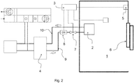
- the cabin conditioning system comprises a control unit 3 for controlling the cabin conditioning system.
- the control unit 3 is arranged to receive signals from sensors and adjust the cabin conditioning system based on the signals.
- the signals may be received from at least one sensor arranged to sense if a hatch 6 to the cabin is opened or closed. If the sensor notices that the hatch 6 is opened, it sends signal to the control unit 3, and the control unit 3 adjusts the cabin conditioning system.
- the cooling medium flow in the system may be adjusted by a control valve 7, which is controlled by the control unit 3.
- the control valve 7 may be opened when the cabin space is needed to be conditioned. When the cabin space is temperature is desired, the control valve 7 may be closed and the cooling medium flow to the air conditioning device 2 is prevented. The control valve 7 may also be closed when for example maintenance work for the air conditioning device 2 is needed.
- the control valve 7 may be located within the first piping 9, which leads the cooling medium into the air conditioning device 2. According to one embodiment, the control valve is located within the second piping 10, which leads the cooling medium from the air conditioning device 2.
- the cabin conditioning system comprises a water heater 8 arranged within the piping leading to the air conditioning device 2.
- the water heater 8 is arranged to heat the cooling medium, flowing into the air conditioning device 2, when needed.
- the temperature of the cooling medium rises fast, and the heated cooling medium flows into the air conditioning device 2 and heats the air conditioning device 2 and the parts of it.
- the water heater 8 may be arranged before the control valve 7 in the cooling medium flowing direction when the control valve 7 is located within the first piping 9.
- the water heater 8 may be an electric heater arranged around the piping or inside the piping in connection with the cooling medium.
- the cabin conditioning system may comprise a second heat exchanger 4 arranged within the cooling medium piping, i.e. the first piping 9 and the second piping 10.
- the second heat exchanger 4 is arranged to transfer thermal energy from the heated cooling medium in the second piping 10 into the cooling medium in the first piping 9.
- the second heat exchanger 4 may be provided before the water heater 8 in the flow direction of the cooling medium towards the air conditioning device 2.
- the hatch 6 of the cabin is closed and the cabin conditioning system conditions the cabin air.
- the water heater 8 is off, the control valve 7 is open, and the cooling medium is flowing via the first piping 9 into the air conditioning device.
- the heated cooling medium from the air conditioning device circulates out of the air conditioning device via the second piping 10.
- control valve 7 is located within the first piping 9, but it may be alternatively located within the second piping 10.
- the hatch 6 is opened, and warm and moist outdoor air is entering cabin space 1.
- the first sensor 5 has recognized the opening of the hatch 6 and sent a first signal to the control unit 3.
- the control unit 3 switched on the water heater 8 and may close the control valve 7.
- the closing of the control valve 7 may take several minutes, and, during that time, the water heater 8 heats the cooling medium flowing into the air conditioning device. While the control valve 7 is closing, the water heater 8 has enough time to heat the cooling medium, which further heats the air condition device along its parts and, thus, the water condensation at the surfaces of the air conditioning device may be minimized or prevented.
- the control valve 7 When the control valve 7 is fully closed, the water heater 8 may be switched off.
- the closing of the control valve 7 is timed.
- the control valve 7 may be timed to close in 4 minutes, wherein the water heater 8 has enough time to heat the cooling medium and further the air conditioning device temperature above the dew point of the cabin air.
- the air conditioning device 2 comprises a temperature sensor for measuring the surface temperature of the air conditioning device 2, and the control valve 7 may be closed when the temperature of the air conditioning device has fallen below the dew point of the cabin air 1.
- the air conditioning device may comprise a condensation watch arranged to watch if condensation is formed on the surface of the air conditioning device or parts of it.
- the hatch 6 is again closed, and no more warm and moist outdoor air is entering the cabin space 1.
- the first sensor 5 has recognized that the hatch 6 is closed and sent a second signal to the control unit 3.
- the control unit 3 has started to open the control valve 7, but the water heater 8 is switched on until the excess moisture in the cabin has been taken away by the ventilation.
- the water heater 8 is switched off when the humidity of the cabin air is under desired or when pre-determined time from the closing of the hatch has passed. When the water heater 8 is switched off, the system is working again according to figure 1 .
- the cabin conditioning system may comprise plurality of sensors for measuring at least one air characteristic inside the cabin space 1.
- the air characteristic may be at least one of the following: air temperature in the cabin or outside the cabin, humidity, unwanted particles, carbon-monoxide etc..
- the sensors are connected to the control unit and control unit is arranged to adjust the air conditioning system based on the signals received from the sensors.
- the cabin conditioning system comprises humidity sensor for measuring the humidity of the cabin air.
- the system may wait until the humidity of the cabin air is lowered back to desired level before opening the control valve 7 and starting to condition the cabin air.
- the humidity of the cabin air is lowered by the ventilation when the hatch 6 is closed.
- the air conditioning system comprises one sensor for measuring cabin air temperature and one sensor for measuring cabin air humidity.
- the control unit compare the humidity level to the temperature of the cabin air, and switch on the water heater if there is possibility for condensation. Further, the control unit is arranged to switch off the water heater if there is no risk for condensation.
- the closing of the control valve 7 is timed.
- the control valve 7 may be timed to close in 10 minutes after the hatch 6 is closed. During that time, the ventilation of the cabin has taken away the excess moisture.
- the cabin conditioning system may be operated by a user interface 11 provided inside the cabin.
- the user may set desired values for example regarding room temperature or the system may be turned on and off.
- the user interface may be a display with separate buttons, or it may be a touch display, through which the user may adjust the cabin conditioning system.
- the cabin conditioning system may be used for heating the cabin space 1.
- the control unit 3 may switch on the water heater 8 and keep the control valve 7 open.
- the cooling medium flown inside the first piping towards the air conditioning device 2 is heated and the heat is transferred into the cabin air by the chilled beam and/or the radiant panel.
- the cabin conditioning system may comprise a temperature sensor for measuring the cabin air temperature and send signals to the control unit 3, based on the temperature, which adjusts the cabin conditioning system for heating or cooling the cabin space 1.
- the user interface may be used for setting desired temperature and/or to ask more hot or cold air into the cabin space.
Landscapes
- Engineering & Computer Science (AREA)
- Chemical & Material Sciences (AREA)
- Combustion & Propulsion (AREA)
- Mechanical Engineering (AREA)
- General Engineering & Computer Science (AREA)
- Ocean & Marine Engineering (AREA)
- Air Conditioning Control Device (AREA)
- Air-Conditioning For Vehicles (AREA)
Priority Applications (4)
| Application Number | Priority Date | Filing Date | Title |
|---|---|---|---|
| EP19194911.4A EP3786055B1 (fr) | 2019-09-02 | 2019-09-02 | Système et procédé de conditionnement d'air de cabine |
| PL19194911T PL3786055T3 (pl) | 2019-09-02 | 2019-09-02 | System klimatyzacji kabiny i sposób klimatyzacji kabiny |
| ES19194911T ES2905432T3 (es) | 2019-09-02 | 2019-09-02 | Sistema de acondicionamiento de aire para un camarote y procedimiento para el acondicionamiento del aire de un camarote |
| HRP20220226TT HRP20220226T1 (hr) | 2019-09-02 | 2019-09-02 | Sustav klimatizacije kabine i način klimatizacije kabine |
Applications Claiming Priority (1)
| Application Number | Priority Date | Filing Date | Title |
|---|---|---|---|
| EP19194911.4A EP3786055B1 (fr) | 2019-09-02 | 2019-09-02 | Système et procédé de conditionnement d'air de cabine |
Publications (2)
| Publication Number | Publication Date |
|---|---|
| EP3786055A1 true EP3786055A1 (fr) | 2021-03-03 |
| EP3786055B1 EP3786055B1 (fr) | 2021-12-01 |
Family
ID=67840985
Family Applications (1)
| Application Number | Title | Priority Date | Filing Date |
|---|---|---|---|
| EP19194911.4A Active EP3786055B1 (fr) | 2019-09-02 | 2019-09-02 | Système et procédé de conditionnement d'air de cabine |
Country Status (4)
| Country | Link |
|---|---|
| EP (1) | EP3786055B1 (fr) |
| ES (1) | ES2905432T3 (fr) |
| HR (1) | HRP20220226T1 (fr) |
| PL (1) | PL3786055T3 (fr) |
Cited By (2)
| Publication number | Priority date | Publication date | Assignee | Title |
|---|---|---|---|---|
| CN115158629A (zh) * | 2022-08-05 | 2022-10-11 | 上海外高桥造船有限公司 | 客船典型内舱房住舱空调装置 |
| CN115195986A (zh) * | 2022-05-20 | 2022-10-18 | 江苏科技大学 | 氢燃料电池船的舱内散热通风系统 |
Citations (3)
| Publication number | Priority date | Publication date | Assignee | Title |
|---|---|---|---|---|
| EP2128536A2 (fr) * | 2008-05-28 | 2009-12-02 | Kariner Oy | Appareil et procédés pour la climatisation d'air par le plafond |
| US20150251743A1 (en) * | 2014-03-06 | 2015-09-10 | Riteaire Marine Llc | Marine vessel dehumidification system |
| DE102017125758A1 (de) * | 2017-11-03 | 2019-05-09 | Emco Klima Gmbh | Dezentrale Klimatisierung von Schiffskabinen |
-
2019
- 2019-09-02 HR HRP20220226TT patent/HRP20220226T1/hr unknown
- 2019-09-02 ES ES19194911T patent/ES2905432T3/es active Active
- 2019-09-02 PL PL19194911T patent/PL3786055T3/pl unknown
- 2019-09-02 EP EP19194911.4A patent/EP3786055B1/fr active Active
Patent Citations (3)
| Publication number | Priority date | Publication date | Assignee | Title |
|---|---|---|---|---|
| EP2128536A2 (fr) * | 2008-05-28 | 2009-12-02 | Kariner Oy | Appareil et procédés pour la climatisation d'air par le plafond |
| US20150251743A1 (en) * | 2014-03-06 | 2015-09-10 | Riteaire Marine Llc | Marine vessel dehumidification system |
| DE102017125758A1 (de) * | 2017-11-03 | 2019-05-09 | Emco Klima Gmbh | Dezentrale Klimatisierung von Schiffskabinen |
Cited By (4)
| Publication number | Priority date | Publication date | Assignee | Title |
|---|---|---|---|---|
| CN115195986A (zh) * | 2022-05-20 | 2022-10-18 | 江苏科技大学 | 氢燃料电池船的舱内散热通风系统 |
| CN115195986B (zh) * | 2022-05-20 | 2023-12-22 | 江苏科技大学 | 氢燃料电池船的舱内散热通风系统 |
| CN115158629A (zh) * | 2022-08-05 | 2022-10-11 | 上海外高桥造船有限公司 | 客船典型内舱房住舱空调装置 |
| CN115158629B (zh) * | 2022-08-05 | 2023-11-03 | 上海外高桥造船有限公司 | 客船典型内舱房住舱空调装置 |
Also Published As
| Publication number | Publication date |
|---|---|
| HRP20220226T1 (hr) | 2022-04-29 |
| ES2905432T3 (es) | 2022-04-08 |
| EP3786055B1 (fr) | 2021-12-01 |
| PL3786055T3 (pl) | 2022-05-23 |
Similar Documents
| Publication | Publication Date | Title |
|---|---|---|
| US6123147A (en) | Humidity control apparatus for residential air conditioning system | |
| JP6800333B2 (ja) | 空気調和機及び空気調和システム | |
| US9943011B2 (en) | Cooling control for data centers with cold aisle containment systems | |
| CA1168446A (fr) | Ventilateur d'adduction-extraction a serpentins de chauffe et de refroidissement, et modes de fonctionnement connexe | |
| JP2015172472A (ja) | 空調用換気装置 | |
| EP3786055B1 (fr) | Système et procédé de conditionnement d'air de cabine | |
| JP2021004724A (ja) | 空調システム | |
| EP2450641B1 (fr) | Installation pour la récupération de chaleur de l'air d'évacuation utilisant une pompe à chaleur, et bâtiment comportant cette installation | |
| KR102158442B1 (ko) | 하이브리드 복사냉각시스템 및 그 작동방법 | |
| JP6570766B2 (ja) | 暖房制御システムおよびヒートポンプ給湯暖房システム | |
| US20160209076A1 (en) | Lighting control for chilled beam | |
| CA3039300A1 (fr) | Dispositif de controle d'unites de serpentin de ventilateur de cvca | |
| EP3688376B1 (fr) | Climatiseur portable et méthode de contrôle | |
| KR100692269B1 (ko) | 직렬연결형 전수식 냉난방시스템 | |
| US3459257A (en) | Room cooling system | |
| JPH02166351A (ja) | ヒートポンプ式冷暖房給湯装置 | |
| JPH0536692B2 (fr) | ||
| JP2002315448A (ja) | 生物育成装置 | |
| EP2017538A2 (fr) | Système de climatisation pour habitation familiale | |
| JP7213061B2 (ja) | 温調装置 | |
| KR102111585B1 (ko) | 밀폐계 냉각수 폐열 활용 외조기 시스템 | |
| US12152803B2 (en) | Lighting control for chilled beam | |
| JPH02101337A (ja) | 空気調和システム | |
| JP7742525B2 (ja) | 浴室空調機 | |
| JP2002228294A (ja) | エンジン冷却方法及び装置並びに冷凍装置 |
Legal Events
| Date | Code | Title | Description |
|---|---|---|---|
| REG | Reference to a national code |
Ref country code: HR Ref legal event code: TUEP Ref document number: P20220226 Country of ref document: HR |
|
| PUAI | Public reference made under article 153(3) epc to a published international application that has entered the european phase |
Free format text: ORIGINAL CODE: 0009012 |
|
| STAA | Information on the status of an ep patent application or granted ep patent |
Free format text: STATUS: REQUEST FOR EXAMINATION WAS MADE |
|
| 17P | Request for examination filed |
Effective date: 20200602 |
|
| AK | Designated contracting states |
Kind code of ref document: A1 Designated state(s): AL AT BE BG CH CY CZ DE DK EE ES FI FR GB GR HR HU IE IS IT LI LT LU LV MC MK MT NL NO PL PT RO RS SE SI SK SM TR |
|
| AX | Request for extension of the european patent |
Extension state: BA ME |
|
| GRAP | Despatch of communication of intention to grant a patent |
Free format text: ORIGINAL CODE: EPIDOSNIGR1 |
|
| STAA | Information on the status of an ep patent application or granted ep patent |
Free format text: STATUS: GRANT OF PATENT IS INTENDED |
|
| INTG | Intention to grant announced |
Effective date: 20210624 |
|
| GRAS | Grant fee paid |
Free format text: ORIGINAL CODE: EPIDOSNIGR3 |
|
| GRAA | (expected) grant |
Free format text: ORIGINAL CODE: 0009210 |
|
| STAA | Information on the status of an ep patent application or granted ep patent |
Free format text: STATUS: THE PATENT HAS BEEN GRANTED |
|
| AK | Designated contracting states |
Kind code of ref document: B1 Designated state(s): AL AT BE BG CH CY CZ DE DK EE ES FI FR GB GR HR HU IE IS IT LI LT LU LV MC MK MT NL NO PL PT RO RS SE SI SK SM TR |
|
| REG | Reference to a national code |
Ref country code: GB Ref legal event code: FG4D |
|
| REG | Reference to a national code |
Ref country code: AT Ref legal event code: REF Ref document number: 1451523 Country of ref document: AT Kind code of ref document: T Effective date: 20211215 Ref country code: CH Ref legal event code: EP |
|
| REG | Reference to a national code |
Ref country code: IE Ref legal event code: FG4D |
|
| REG | Reference to a national code |
Ref country code: DE Ref legal event code: R096 Ref document number: 602019009667 Country of ref document: DE |
|
| REG | Reference to a national code |
Ref country code: FI Ref legal event code: FGE |
|
| REG | Reference to a national code |
Ref country code: NO Ref legal event code: T2 Effective date: 20211201 |
|
| REG | Reference to a national code |
Ref country code: NL Ref legal event code: FP |
|
| REG | Reference to a national code |
Ref country code: LT Ref legal event code: MG9D |
|
| REG | Reference to a national code |
Ref country code: ES Ref legal event code: FG2A Ref document number: 2905432 Country of ref document: ES Kind code of ref document: T3 Effective date: 20220408 |
|
| REG | Reference to a national code |
Ref country code: AT Ref legal event code: MK05 Ref document number: 1451523 Country of ref document: AT Kind code of ref document: T Effective date: 20211201 |
|
| PG25 | Lapsed in a contracting state [announced via postgrant information from national office to epo] |
Ref country code: RS Free format text: LAPSE BECAUSE OF FAILURE TO SUBMIT A TRANSLATION OF THE DESCRIPTION OR TO PAY THE FEE WITHIN THE PRESCRIBED TIME-LIMIT Effective date: 20211201 Ref country code: LT Free format text: LAPSE BECAUSE OF FAILURE TO SUBMIT A TRANSLATION OF THE DESCRIPTION OR TO PAY THE FEE WITHIN THE PRESCRIBED TIME-LIMIT Effective date: 20211201 Ref country code: BG Free format text: LAPSE BECAUSE OF FAILURE TO SUBMIT A TRANSLATION OF THE DESCRIPTION OR TO PAY THE FEE WITHIN THE PRESCRIBED TIME-LIMIT Effective date: 20220301 Ref country code: AT Free format text: LAPSE BECAUSE OF FAILURE TO SUBMIT A TRANSLATION OF THE DESCRIPTION OR TO PAY THE FEE WITHIN THE PRESCRIBED TIME-LIMIT Effective date: 20211201 |
|
| REG | Reference to a national code |
Ref country code: HR Ref legal event code: T1PR Ref document number: P20220226 Country of ref document: HR |
|
| PG25 | Lapsed in a contracting state [announced via postgrant information from national office to epo] |
Ref country code: SE Free format text: LAPSE BECAUSE OF FAILURE TO SUBMIT A TRANSLATION OF THE DESCRIPTION OR TO PAY THE FEE WITHIN THE PRESCRIBED TIME-LIMIT Effective date: 20211201 Ref country code: LV Free format text: LAPSE BECAUSE OF FAILURE TO SUBMIT A TRANSLATION OF THE DESCRIPTION OR TO PAY THE FEE WITHIN THE PRESCRIBED TIME-LIMIT Effective date: 20211201 Ref country code: GR Free format text: LAPSE BECAUSE OF FAILURE TO SUBMIT A TRANSLATION OF THE DESCRIPTION OR TO PAY THE FEE WITHIN THE PRESCRIBED TIME-LIMIT Effective date: 20220302 |
|
| PG25 | Lapsed in a contracting state [announced via postgrant information from national office to epo] |
Ref country code: SM Free format text: LAPSE BECAUSE OF FAILURE TO SUBMIT A TRANSLATION OF THE DESCRIPTION OR TO PAY THE FEE WITHIN THE PRESCRIBED TIME-LIMIT Effective date: 20211201 Ref country code: SK Free format text: LAPSE BECAUSE OF FAILURE TO SUBMIT A TRANSLATION OF THE DESCRIPTION OR TO PAY THE FEE WITHIN THE PRESCRIBED TIME-LIMIT Effective date: 20211201 Ref country code: RO Free format text: LAPSE BECAUSE OF FAILURE TO SUBMIT A TRANSLATION OF THE DESCRIPTION OR TO PAY THE FEE WITHIN THE PRESCRIBED TIME-LIMIT Effective date: 20211201 Ref country code: PT Free format text: LAPSE BECAUSE OF FAILURE TO SUBMIT A TRANSLATION OF THE DESCRIPTION OR TO PAY THE FEE WITHIN THE PRESCRIBED TIME-LIMIT Effective date: 20220401 Ref country code: EE Free format text: LAPSE BECAUSE OF FAILURE TO SUBMIT A TRANSLATION OF THE DESCRIPTION OR TO PAY THE FEE WITHIN THE PRESCRIBED TIME-LIMIT Effective date: 20211201 Ref country code: CZ Free format text: LAPSE BECAUSE OF FAILURE TO SUBMIT A TRANSLATION OF THE DESCRIPTION OR TO PAY THE FEE WITHIN THE PRESCRIBED TIME-LIMIT Effective date: 20211201 |
|
| REG | Reference to a national code |
Ref country code: DE Ref legal event code: R097 Ref document number: 602019009667 Country of ref document: DE |
|
| REG | Reference to a national code |
Ref country code: HR Ref legal event code: ODRP Ref document number: P20220226 Country of ref document: HR Payment date: 20220824 Year of fee payment: 4 |
|
| PG25 | Lapsed in a contracting state [announced via postgrant information from national office to epo] |
Ref country code: IS Free format text: LAPSE BECAUSE OF FAILURE TO SUBMIT A TRANSLATION OF THE DESCRIPTION OR TO PAY THE FEE WITHIN THE PRESCRIBED TIME-LIMIT Effective date: 20220401 |
|
| PLBE | No opposition filed within time limit |
Free format text: ORIGINAL CODE: 0009261 |
|
| STAA | Information on the status of an ep patent application or granted ep patent |
Free format text: STATUS: NO OPPOSITION FILED WITHIN TIME LIMIT |
|
| PG25 | Lapsed in a contracting state [announced via postgrant information from national office to epo] |
Ref country code: DK Free format text: LAPSE BECAUSE OF FAILURE TO SUBMIT A TRANSLATION OF THE DESCRIPTION OR TO PAY THE FEE WITHIN THE PRESCRIBED TIME-LIMIT Effective date: 20211201 Ref country code: AL Free format text: LAPSE BECAUSE OF FAILURE TO SUBMIT A TRANSLATION OF THE DESCRIPTION OR TO PAY THE FEE WITHIN THE PRESCRIBED TIME-LIMIT Effective date: 20211201 |
|
| 26N | No opposition filed |
Effective date: 20220902 |
|
| PG25 | Lapsed in a contracting state [announced via postgrant information from national office to epo] |
Ref country code: MC Free format text: LAPSE BECAUSE OF FAILURE TO SUBMIT A TRANSLATION OF THE DESCRIPTION OR TO PAY THE FEE WITHIN THE PRESCRIBED TIME-LIMIT Effective date: 20211201 |
|
| REG | Reference to a national code |
Ref country code: CH Ref legal event code: PL |
|
| REG | Reference to a national code |
Ref country code: BE Ref legal event code: MM Effective date: 20220930 |
|
| PG25 | Lapsed in a contracting state [announced via postgrant information from national office to epo] |
Ref country code: LU Free format text: LAPSE BECAUSE OF NON-PAYMENT OF DUE FEES Effective date: 20220902 |
|
| PG25 | Lapsed in a contracting state [announced via postgrant information from national office to epo] |
Ref country code: LI Free format text: LAPSE BECAUSE OF NON-PAYMENT OF DUE FEES Effective date: 20220930 Ref country code: IE Free format text: LAPSE BECAUSE OF NON-PAYMENT OF DUE FEES Effective date: 20220902 Ref country code: CH Free format text: LAPSE BECAUSE OF NON-PAYMENT OF DUE FEES Effective date: 20220930 |
|
| REG | Reference to a national code |
Ref country code: HR Ref legal event code: ODRP Ref document number: P20220226 Country of ref document: HR Payment date: 20230816 Year of fee payment: 5 |
|
| PG25 | Lapsed in a contracting state [announced via postgrant information from national office to epo] |
Ref country code: BE Free format text: LAPSE BECAUSE OF NON-PAYMENT OF DUE FEES Effective date: 20220930 |
|
| PG25 | Lapsed in a contracting state [announced via postgrant information from national office to epo] |
Ref country code: CY Free format text: LAPSE BECAUSE OF FAILURE TO SUBMIT A TRANSLATION OF THE DESCRIPTION OR TO PAY THE FEE WITHIN THE PRESCRIBED TIME-LIMIT Effective date: 20211201 |
|
| PG25 | Lapsed in a contracting state [announced via postgrant information from national office to epo] |
Ref country code: MK Free format text: LAPSE BECAUSE OF FAILURE TO SUBMIT A TRANSLATION OF THE DESCRIPTION OR TO PAY THE FEE WITHIN THE PRESCRIBED TIME-LIMIT Effective date: 20211201 Ref country code: HU Free format text: LAPSE BECAUSE OF FAILURE TO SUBMIT A TRANSLATION OF THE DESCRIPTION OR TO PAY THE FEE WITHIN THE PRESCRIBED TIME-LIMIT; INVALID AB INITIO Effective date: 20190902 |
|
| REG | Reference to a national code |
Ref country code: HR Ref legal event code: ODRP Ref document number: P20220226 Country of ref document: HR Payment date: 20240819 Year of fee payment: 6 |
|
| PG25 | Lapsed in a contracting state [announced via postgrant information from national office to epo] |
Ref country code: MT Free format text: LAPSE BECAUSE OF FAILURE TO SUBMIT A TRANSLATION OF THE DESCRIPTION OR TO PAY THE FEE WITHIN THE PRESCRIBED TIME-LIMIT Effective date: 20211201 |
|
| REG | Reference to a national code |
Ref country code: HR Ref legal event code: ODRP Ref document number: P20220226 Country of ref document: HR Payment date: 20250818 Year of fee payment: 7 |
|
| PGFP | Annual fee paid to national office [announced via postgrant information from national office to epo] |
Ref country code: FI Payment date: 20250917 Year of fee payment: 7 |
|
| PGFP | Annual fee paid to national office [announced via postgrant information from national office to epo] |
Ref country code: DE Payment date: 20250917 Year of fee payment: 7 |
|
| PGFP | Annual fee paid to national office [announced via postgrant information from national office to epo] |
Ref country code: NO Payment date: 20250922 Year of fee payment: 7 |
|
| PGFP | Annual fee paid to national office [announced via postgrant information from national office to epo] |
Ref country code: TR Payment date: 20250822 Year of fee payment: 7 Ref country code: PL Payment date: 20250819 Year of fee payment: 7 Ref country code: NL Payment date: 20250916 Year of fee payment: 7 Ref country code: IT Payment date: 20250918 Year of fee payment: 7 |
|
| PGFP | Annual fee paid to national office [announced via postgrant information from national office to epo] |
Ref country code: GB Payment date: 20250916 Year of fee payment: 7 |
|
| PGFP | Annual fee paid to national office [announced via postgrant information from national office to epo] |
Ref country code: HR Payment date: 20250818 Year of fee payment: 7 |
|
| PGFP | Annual fee paid to national office [announced via postgrant information from national office to epo] |
Ref country code: FR Payment date: 20250917 Year of fee payment: 7 |
|
| PGFP | Annual fee paid to national office [announced via postgrant information from national office to epo] |
Ref country code: ES Payment date: 20251006 Year of fee payment: 7 |
|
| PG25 | Lapsed in a contracting state [announced via postgrant information from national office to epo] |
Ref country code: SI Free format text: LAPSE BECAUSE OF FAILURE TO SUBMIT A TRANSLATION OF THE DESCRIPTION OR TO PAY THE FEE WITHIN THE PRESCRIBED TIME-LIMIT Effective date: 20211201 |