EP3786367A2 - Procédés et système de stabilisation - Google Patents
Procédés et système de stabilisation Download PDFInfo
- Publication number
- EP3786367A2 EP3786367A2 EP20192722.5A EP20192722A EP3786367A2 EP 3786367 A2 EP3786367 A2 EP 3786367A2 EP 20192722 A EP20192722 A EP 20192722A EP 3786367 A2 EP3786367 A2 EP 3786367A2
- Authority
- EP
- European Patent Office
- Prior art keywords
- inflatable element
- inflatable
- pressure level
- stabilizing
- gap
- Prior art date
- Legal status (The legal status is an assumption and is not a legal conclusion. Google has not performed a legal analysis and makes no representation as to the accuracy of the status listed.)
- Pending
Links
Images






Classifications
-
- E—FIXED CONSTRUCTIONS
- E02—HYDRAULIC ENGINEERING; FOUNDATIONS; SOIL SHIFTING
- E02B—HYDRAULIC ENGINEERING
- E02B17/00—Artificial islands mounted on piles or like supports, e.g. platforms on raisable legs or offshore constructions; Construction methods therefor
- E02B17/02—Artificial islands mounted on piles or like supports, e.g. platforms on raisable legs or offshore constructions; Construction methods therefor placed by lowering the supporting construction to the bottom, e.g. with subsequent fixing thereto
- E02B17/027—Artificial islands mounted on piles or like supports, e.g. platforms on raisable legs or offshore constructions; Construction methods therefor placed by lowering the supporting construction to the bottom, e.g. with subsequent fixing thereto steel structures
-
- E—FIXED CONSTRUCTIONS
- E02—HYDRAULIC ENGINEERING; FOUNDATIONS; SOIL SHIFTING
- E02B—HYDRAULIC ENGINEERING
- E02B17/00—Artificial islands mounted on piles or like supports, e.g. platforms on raisable legs or offshore constructions; Construction methods therefor
- E02B17/04—Equipment specially adapted for raising, lowering, or immobilising the working platform relative to the supporting construction
- E02B17/08—Equipment specially adapted for raising, lowering, or immobilising the working platform relative to the supporting construction for raising or lowering
- E02B17/0836—Equipment specially adapted for raising, lowering, or immobilising the working platform relative to the supporting construction for raising or lowering with climbing jacks
- E02B17/0845—Equipment specially adapted for raising, lowering, or immobilising the working platform relative to the supporting construction for raising or lowering with climbing jacks with inflatable clamping rings
-
- B—PERFORMING OPERATIONS; TRANSPORTING
- B63—SHIPS OR OTHER WATERBORNE VESSELS; RELATED EQUIPMENT
- B63B—SHIPS OR OTHER WATERBORNE VESSELS; EQUIPMENT FOR SHIPPING
- B63B35/00—Vessels or similar floating structures specially adapted for specific purposes and not otherwise provided for
- B63B35/44—Floating buildings, stores, drilling platforms, or workshops, e.g. carrying water-oil separating devices
-
- B—PERFORMING OPERATIONS; TRANSPORTING
- B63—SHIPS OR OTHER WATERBORNE VESSELS; RELATED EQUIPMENT
- B63B—SHIPS OR OTHER WATERBORNE VESSELS; EQUIPMENT FOR SHIPPING
- B63B75/00—Building or assembling floating offshore structures, e.g. semi-submersible platforms, SPAR platforms or wind turbine platforms
-
- E—FIXED CONSTRUCTIONS
- E02—HYDRAULIC ENGINEERING; FOUNDATIONS; SOIL SHIFTING
- E02B—HYDRAULIC ENGINEERING
- E02B17/00—Artificial islands mounted on piles or like supports, e.g. platforms on raisable legs or offshore constructions; Construction methods therefor
-
- E—FIXED CONSTRUCTIONS
- E02—HYDRAULIC ENGINEERING; FOUNDATIONS; SOIL SHIFTING
- E02B—HYDRAULIC ENGINEERING
- E02B17/00—Artificial islands mounted on piles or like supports, e.g. platforms on raisable legs or offshore constructions; Construction methods therefor
- E02B17/0008—Methods for grouting offshore structures; apparatus therefor
-
- E—FIXED CONSTRUCTIONS
- E02—HYDRAULIC ENGINEERING; FOUNDATIONS; SOIL SHIFTING
- E02B—HYDRAULIC ENGINEERING
- E02B17/00—Artificial islands mounted on piles or like supports, e.g. platforms on raisable legs or offshore constructions; Construction methods therefor
- E02B17/04—Equipment specially adapted for raising, lowering, or immobilising the working platform relative to the supporting construction
-
- B—PERFORMING OPERATIONS; TRANSPORTING
- B63—SHIPS OR OTHER WATERBORNE VESSELS; RELATED EQUIPMENT
- B63B—SHIPS OR OTHER WATERBORNE VESSELS; EQUIPMENT FOR SHIPPING
- B63B35/00—Vessels or similar floating structures specially adapted for specific purposes and not otherwise provided for
- B63B35/44—Floating buildings, stores, drilling platforms, or workshops, e.g. carrying water-oil separating devices
- B63B2035/4433—Floating structures carrying electric power plants
- B63B2035/446—Floating structures carrying electric power plants for converting wind energy into electric energy
-
- E—FIXED CONSTRUCTIONS
- E02—HYDRAULIC ENGINEERING; FOUNDATIONS; SOIL SHIFTING
- E02B—HYDRAULIC ENGINEERING
- E02B17/00—Artificial islands mounted on piles or like supports, e.g. platforms on raisable legs or offshore constructions; Construction methods therefor
- E02B2017/0039—Methods for placing the offshore structure
-
- E—FIXED CONSTRUCTIONS
- E02—HYDRAULIC ENGINEERING; FOUNDATIONS; SOIL SHIFTING
- E02B—HYDRAULIC ENGINEERING
- E02B17/00—Artificial islands mounted on piles or like supports, e.g. platforms on raisable legs or offshore constructions; Construction methods therefor
- E02B2017/0091—Offshore structures for wind turbines
Definitions
- the present invention relates to methods of stabilizing and/or lifting and/or separating a first structure relative to a second structure, an associated system, and a method of installation.
- the methods and system may find utility offshore and/or in a marine environment.
- Offshore structures such as offshore wind turbines, may be supported and/or mounted by a support structure, such as for example a jacket.
- the jacket may typically have three or four legs, which may be arranged to form a lattice structure.
- Jackets can be lowered onto pre-installed piles. The piles may be installed by driving them into the seabed using a piling hammer and/or a piling template.
- the jacket may be permanently fixed to the piles, for example, by forming a cemented or grouted connection between the jacket and the piles.
- the cemented or grouted connection may transfer loads between the jacket and the piles.
- Subsea packers and/or grippers may be used in the offshore industry for stabilizing or securing a support structure relative to a foundation, such as stabilizing a jacket relative to a pile, during installation.
- Such packers and/or grippers are described in UK Patent Application No. 1814224.0 (W3G Marine Ltd), which is hereby incorporated by reference in their entirety.
- packers and/or grippers may find utility in other environments, such as in the construction industry for purposes of stabilizing, or lifting, e.g., jacking, a structure relative to another structure.
- a method of stabilizing and/or lifting and/or separating a first structure relative to a second structure may comprise one or more of the steps of: determining a volume of fluid required to inflate an inflatable element disposed in a gap between the first and second structures to a first pressure level; based on the volume of fluid required and characteristics of the inflatable element, determining a second pressure level required to provide a desired stabilizing and/or lifting and/or separating force to be applied to the structures by the inflatable element; and (further) inflating the inflatable element to the second pressure level.
- stabilization and/or lifting and/or separating of the first structure relative to the second structure may be carried out without direct visibility of the structures and/or inflatable element(s).
- a first pressure level i.e. a first predetermined pressure level
- stabilization and/or lifting and/or separating of the first structure relative to the second structure may be carried out without direct visibility of the structures and/or inflatable element(s).
- an inflatable element disposed between the first and second structure may be below sea-level, thus inhibiting visibility of the inflatable element.
- controlling a stabilizing and/or lifting and/or separating effect of the inflatable element by means of measuring a volume of fluid used to inflate the element, in addition to predetermined characteristic of the inflatable element, permits remote operation of the element, i.e. control of pressurisation and/or depressurization from surface.
- the step of determining a second pressure level may further comprise determining a size of the gap based on the volume of fluid required and a first characteristic of the inflatable element.
- the step of determining a second pressure level may further comprise making a determination of the second pressure level based on the determined size of the gap and a second characteristic of the inflatable element.
- the step of further inflating the inflatable element to the second pressure level may comprises the step of initially inflating the inflatable element to a third pressure level, the third pressure level being substantially greater than the second pressure level.
- the step of further inflating the inflatable element to the second pressure level may comprises the step of subsequently deflating the inflatable element to the second pressure level.
- a deformation of the inflatable element may be maximised.
- a surface area of the inflatable element in contact with, and thus applying a force to, the first and/or second structure may be maximised.
- the determination of the third pressure level may be based on the determined size of the gap and a third characteristic of the inflatable element.
- the first characteristic may be a relationship between the size of the gap and a volume of fluid required to inflate the inflatable element to the first pressure level.
- the second characteristic may be a relationship between the size of the gap and pressure level required to provide the desired stabilizing force and/or a force that incurs a required, or maximum, deformation of the inflatable element.
- the third characteristic may be a relationship between the size of the gap and a pressure level required to provide the desired stabilizing force and/or a force that incurs a required, or maximum, deformation of the inflatable element.
- the first and/or second and/or third characteristics may be predetermined characteristics.
- the method may comprise the step of characterising the inflatable element by means of simulation and/or testing to determine the first and/or second and/or third characteristics.
- such characterisation of the inflatable element may be carried out at low cost, and avoids a requirement for in situ testing of the inflatable element.
- the method may comprise the step of characterising a further inflatable element equivalent, similar or comparable to the inflatable element, by means of simulation and/or testing to determine the first and/or second and/or third characteristics.
- costs and resource requirements may be minimised by performing characterisation in an off-line and typically on-shore situation, and/or by using a lower-cost equivalent of the inflatable element used in practice.
- the method may comprise the step of disposing the at least one inflatable element in the gap between the first and second structures.
- the at least one inflatable element may be disposed on the first or second structures prior to the first and second structures being disposed relative to each other to form the gap.
- the method may further comprise the step of testing the integrity of the inflatable element.
- Testing the integrity of the inflatable element may comprise decreasing the pressure in the inflatable element to a pressure level below a default pressure.
- Testing the integrity of the inflatable element further comprise assessing, e.g. subsequently assessing, whether the pressure level below the default pressure is sustained after a period of time.
- such an integrity test avoids excessively deforming the inflatable elements prior to use. By avoiding excessive deformation, if can be ensured that the first structure can be disposed relative to the second structure without interfering with, e.g. damaging, the inflatable element.
- the determination of the volume of fluid required to inflate the inflatable element may be made or performed using a flow meter.
- the flow meter may be communicably coupled to the inflatable element.
- a determination of a pressure level in the inflatable element when inflating or deflating the inflatable element may be made or performed using a pressure gauge.
- the pressure gauge may be communicably coupled to the inflatable element.
- the first or second structure may comprise a jacket, such as a jacket for supporting a wind turbine.
- the first or second structure may be a leg of a jacket.
- the first structure may be substantially cylindrical.
- the other of the first or second structure may comprise a foundation, such as a subsea pile.
- the first structure may be substantially cylindrical.
- the first structure may be disposed within the second structure, or vice versa.
- an outer surface of the first structure may be arranged within, or be substantially enclosed by, an inner surface of the second structure.
- the first and or second structures may be arranged substantially concentrically with each other.
- the gap may be an annulus between the first and second structures.
- the method may further comprise the step of disposing grout, such as concrete, within the gap after the first structure is stabilized and/or lifted and/or separated relative to the second structure.
- grout such as concrete
- Such grout may prevent movement, e.g. further movement, of the first structure relative to the second structure.
- the fluid may comprise sea-water.
- the fluid may be purified or filtered water.
- the fluid may be a liquid, such as hydraulic fluid, an oil, or the like.
- the gap may be disposed below a surface of the sea.
- pressurisation and/or depressurisation of the inflatable element may be controlled from surface.
- a method of stabilizing and/or lifting and/or separating a first structure relative to a second structure comprising the steps of: determining a volume of fluid required to inflate each inflatable element of a plurality of inflatable elements disposed in a gap between the first and second structures to a first pressure level; based on the volume of fluid required and a characteristics of each inflatable element, determining a pressure level required for each inflatable element to provide a desired stabilizing and/or lifting and/or separating force to be applied to the structures by the inflatable element; and further inflating each inflatable element to the respective determined pressure level.
- a stabilizing and/or lifting and/or separating force may be distributed across or around one or more surfaces of the first and/or second structure.
- the step of determining a pressure level required for each inflatable element may comprise determining a pressure level required for each inflatable element to provide a desired stabilizing and/or lifting and/or separating force to be applied to the structures by the inflatable element based on the determined size of each gap and a second characteristic of each inflatable element.
- the plurality of inflatable elements may comprise at least one pair of inflatable elements.
- the method may further comprise a step, e.g. an initial step, of disposing at least one pair of inflatable elements in the gap between the first and second structures, such that the at least one pair of inflatable elements are disposed at substantially opposite, or opposing, sides of the structures.
- a step e.g. an initial step, of disposing at least one pair of inflatable elements in the gap between the first and second structures, such that the at least one pair of inflatable elements are disposed at substantially opposite, or opposing, sides of the structures.
- substantially equal and opposite forces may be more readily applied to substantially opposite sides of the first and second structures, thus further stabilizing the first structure relative to the second structure.
- the method may further comprise a step, e.g. an initial step, of circumferentially disposing, or substantially circumferentially disposing, a plurality of inflatable elements in an annular gap between the first and second structures.
- a step e.g. an initial step, of circumferentially disposing, or substantially circumferentially disposing, a plurality of inflatable elements in an annular gap between the first and second structures.
- the step of further inflating each inflatable element to the respective determined pressure level may comprise further inflating each inflatable element such that substantially equal and/or opposing stabilizing and/or lifting and/or separating forces are applied to the to the structures by the at least one pair of inflatable elements.
- a method of stabilizing and/or lifting and/or separating a first structure relative to a second structure comprising the steps of: disposing a plurality of inflatable elements in a gap between the first and second structures; based on a determined size of the gap and a characteristic of the inflatable element, determining a pressure level required in each inflatable element to apply equal substantially stabilizing and/or lifting and/or separating forces to the structures by the each of the inflatable elements; and inflating each inflatable element to the respective required pressure level.
- the plurality of inflatable elements may be arranged as one or more substantially opposing pairs of inflatable elements, such that the stabilizing and/or lifting and/or separating forces from each inflatable element of a pair of inflatable elements are applied in substantially opposing directions.
- the plurality of inflatable elements may be evenly distributed in the gap.
- the gap may be an annulus between the first and second structures.
- a method of stabilizing and/or lifting and/or separating a first structure relative to a second structure comprising the steps of: determining a required pressure level to provide a desired stabilizing and/or lifting and/or separating force to be applied to the structures by the inflatable element; inflating the inflatable element to pressure level substantially greater than the required pressure level; and deflating the inflatable element to the required pressure level.
- a deformation of the inflatable element may be maximised, thus maximising a surface area of the inflatable element in contact with, and thus applying a force to, the first and/or second structure.
- a system for stabilizing and/or lifting and/or separating a first structure relative to a second structure comprising: at least one inflatable element for disposing between the first structure and the second structure; an arrangement or means for controlling and determining a fluid pressure in the at least one inflatable element; and an arrangement or means for measuring a volume of fluid used to inflate the at least one inflatable element.
- the system may comprise the first structure.
- the system may comprise at least one pair of inflatable elements arranged at substantially opposite or opposing sides of the first structure.
- a periphery of the at least one inflatable element may comprise at least one corner.
- the at least one corner may comprise a concave portion.
- a periphery of the/each inflatable element or cushion may comprises at least one corner.
- the or each at least one corner may comprise a concave portion.
- The/each inflatable element may comprise a plurality of corners. Each corner may comprise a concave portion;
- a periphery of the/each inflatable elements may correspond to a substantially rectilinear shape.
- the substantially rectilinear shape may comprise concave cut-away portions at each corner.
- the periphery of the/each inflatable element may comprise at least one pair of symmetrical sides. Each side of the periphery may comprise a substantially straight portion.
- the at least one concave portion may be joined to an adjacent side of the periphery by at least one curved and/or radiused and/or convex portion.
- a length or extent of the at least one concave portion may be greater than a length or extent of a/the curved, radiused and/or convex portion.
- Each straight portion may be adjoined to an adjacent straight portion by at least one concave portion.
- At least two curved and/or radiused and/or convex portions and/or each straight portion may be adjoined to an adjacent straight portion by, in sequence, a convex portion, a concave portion, and a convex portion.
- the arrangement or means for controlling and determining a fluid pressure in the at least one inflatable element may be a flow meter.
- the flow meter may be communicably coupled to the inflatable element.
- the arrangement or means for measuring a volume of fluid used to inflate the at least one inflatable element may be a pressure gauge.
- the pressure gauge may be communicably coupled to the inflatable element.
- a sixth aspect of the present invention there is provided a method of testing the integrity of the system according to the fifth aspect, the method comprising the steps of: configuring the arrangement or means for controlling and determining a fluid pressure in the at least one inflatable element to decrease a pressure in the inflatable element to a pressure level below a default pressure, and subsequently assessing whether the pressure level below the default pressure is maintained after a period of time.
- the default pressure may be atmospheric pressure.
- the default pressure may correspond to a depth below a surface of the sea of the inflatable element.
- the pressure level below the default pressure may be provided using a pump, such as a vacuum pump.
- a seventh aspect of the present invention there is provided a method for installing an inflatable element for stabilizing and/or lifting and/or separating a first structure relative to a second structure; the method comprising the steps of: providing the first structure with centralisers or supports for respectively centralising or supporting the first structure relative to the second structure; disposing the inflatable element in a deflated configuration between a pair of centralisers or supports, such that the inflatable element in the deflated configuration does not interfere with the second structure when the first structure is centralised or supported relative to the second structure by the centralisers or supports for respectively.
- the step of disposing the inflatable element in a deflated configuration between a pair of centralisers or supports may comprise seating the inflatable element on at least one centraliser or support.
- a first structure configured to support an inflatable element for stabilizing and/or lifting and/or separating the first structure relative to a second structure, the first structure comprising at least three supports and/or centralisers for supporting an inflatable element relative to the first structure.
- the at least three supports and/or centralisers may be arranged in a substantially V-shaped configuration
- the at least three supports and/or centralisers may be mounted on a surface of the first structure.
- the first structure may be a jacket for supporting a wind turbine.
- an apparatus for stabilizing and/or lifting and/or separating a first structure relative to a second structure comprising: a connection arrangement for connecting the apparatus to a support arrangement of a first structure; and a plurality of inflatable elements.
- connection arrangement may be adapted to be slidably and/or releasably engagable with the support arrangement on the first structure.
- connection arrangement may comprise a frame.
- the plurality of inflatable elements may be supported by the frame.
- Each inflatable element may be communicably coupled to a manifold and/or valve supported by the frame.
- a periphery of the/each inflatable element or cushion may comprise at least one corner.
- the or each at least one corner may comprise a concave portion.
- The/each inflatable element may comprise a plurality of corners. Each corner comprises a concave portion.
- a periphery of the/each inflatable element may correspond to a substantially rectilinear shape.
- the substantially rectilinear shape may comprise concave cut-away portions at each corner.
- the periphery of the/each inflatable element may comprise at least one pair of symmetrical sides. Each side of the periphery may comprise a substantially straight portion.
- embodiments of the present invention relating to stabilizing and/or lifting and/or separating may be capable of positioning, locating, securing, jacking, packing, gripping, holding or centralising one item, e.g. member or structure, relative to another item, e.g. member or structure.
- stabilizing and/or lifting and/or “separating” is/are meant to include or comprise any of the aforementioned and at least in some embodiments the terms “stabilizer”, “packer” and “gripper” or “gripping” may be used synonymously or similarly. Such terms also apply in respect of “stabilizing force” and/or “lifting force” and or “separating force”.
- FIG. 1 to 10b there is shown example embodiments of an inflatable element, and examples of methods and systems for installation of such an inflatable element, in accordance with embodiments of the present invention, as will be described below in more detail.
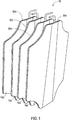
- FIG. 1 shows an inflatable element, generally denoted 10, as described in UK Patent Application No. 1814224.0 (W3G Marine Ltd).
- the inflatable element 10 comprises four inflatable section 15a, 15b, 15c, 15d. It will be appreciated that in other embodiments falling within the scope of the present invention, the inflatable element 10 may comprise fewer than or greater than four inflatable sections.
- the plurality of inflatable sections 15a, 15b, 15c, 15d are arranged in a stack, although for illustrative purposes they are shown in an exploded view in Figure 1 .
- a periphery of each inflatable section 15a, 15b, 15c, 15d comprises four corners, each corner comprising a concave portion 30a, 30b, 30c, 30d. That is, the periphery of each inflatable section 15a, 15b, 15c, 15d corresponds to a substantially rectangular/rectilinear shape with concave cut-away portions 30a, 30b, 30c, 30d at each corner.
- the inflatable sections are communicably coupled.
- FIG. 2 shows a perspective view of a portion of a structure 100 with a plurality of inflatable elements 110, 120 installed.
- the structure 100 is a jacket for supporting an offshore wind turbine. It will be appreciated that the jacket is for example purposes only, and the present invention is equally applicable to other structures, such as structures used in the on-shore building and construction industry.
- the structure 100 comprises a plurality of centralisers or supports 130a-g arranged on an outer surface of the structure 100.
- Each inflatable element 110, 120 is disposed between a pair of centralisers or supports 130a, 130b; 130d, 130e. Furthermore, each inflatable element 110, 120 is seated on a centraliser or support 130f, 130g.That is, at least three of the centralisers or supports 130a, 130b, 130f are arranged in a substantially V-shaped configuration for supporting the inflatable element therebetween 110.
- each inflatable section of an inflatable element 110, 120 is communicably connected to a hose 140, 150.
- Each hose 140, 150 may be an inflation line.
- a plurality of inflatable sections of each inflatable element 110, 120 can be inflated or deflated collectively, i.e. together or in parallel.
- individual control of the inflation and/or deflation of inflatable sections of each inflatable element 110, 120 may be implemented, e.g. by individual hoses connecting each inflatable section of each inflatable element 110, 120.
- the inflatable sections within an inflatable element may be communicably coupled such that a connection by the hose 140, 150 to a single inflatable section may inflate all of the inflatable sections of an inflatable element 110, 120.
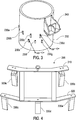
- FIG. 3 there is shown a perspective view of a portion of a structure 200, showing an arrangement of centralisers or supports 230a-g for centralising or supporting structure 200 relative to another structure (not shown).
- the structure 200 comprises a limiter 240 to limit an extent to which the structure 200 can be inserted into a further structure.
- the structure 200 is a portion of a leg of a jacket for supporting an off-shore wind turbine.
- the further structure (not shown) may be a cylindrical pile or foundation, against which the jacket leg is to be secured or stabilized.
- the centralisers or supports 230a-g may be disposed in an annular gap between the structure 200 and the further structure, in use.
- the centralisers or supports 230a-g may serve to guide the structure 200 into the further structure. Furthermore, the centralisers or supports 230a-g may also protect any inflatable element disposed between the centralisers or supports 230a-g during installation of the structure 200 into the further structure. Each inflatable element will have at least three centralisers or supports providing protection.
- Figure 4 shows a perspective view of an example template 300 for installing the centralisers or supports 230a-g shown in Figure 3 .
- the template 300 comprises two substantially parallel bars 310, 320, connected by joining members, e.g. perpendicular struts in the example embodiment of Figure 4 .
- Each bar 310, 320 comprises an arrangement or means for attaching a plurality of centralisers or supports 330a-e.
- Various means may be employed to attach centralisers or supports 330a-e to the template 300, such as bolting, clamping, screwing or the like.
- the template 300 is used to hold a plurality of centralisers or supports 330a-e against a structure.
- the plurality of centralisers or supports 330a-e are then welded, or otherwise adhered or attached to the structure, and the template 300 subsequently removed, e.g. detached from each of the plurality of centralisers or supports 330a-e.
- the plurality of centralisers or supports 300a-e can be fitted to a structure to define a first, upper row of centralisers or supports 330a, 330b and a second, lower row of centralisers or supports 330c, 330d, 330e.
- the plurality of centralisers or supports 330a-e can be fitted and reliably spaced apart such that an inflatable element can be disposed between a pair of centralisers or supports 330a, 330b on the upper row of centralisers or supports, and/or also seated on a centraliser or support 330d in the lower row of centralisers or supports.
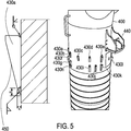
- Figure 5 shows a further example of a structure 400 comprising an arrangement of centralisers or supports 430a-I for centralising or supporting the structure 400 relative to another structure (not shown).
- the structure 400 comprises a limiter 440 to limit an extent to which the structure 400 can be inserted into a further structure.
- the structure 400 is a portion of a leg of a jacket for supporting an off-shore wind turbine.
- the further structure (not shown) may be a cylindrical pile or foundation, against which the jacket leg is to be secured or stabilized.
- the centralisers or supports 430a-I may be disposed in an annular gap between the structure 400 and the further structure.
- FIG. 5 Also shown in Figure 5 is a cross-sectional view of one of the centralisers or supports 430a.
- Each centraliser or support 430a-I is substantially wedge shaped, e.g. tapered, such that a radial extent of the centralisers or supports increase towards an upper portion of the centralisers or supports, thus providing a sloping surface 450 relative to a surface of the structure 400.
- the centralisers or supports may help guide the structure 400 into a further structure (not shown) is use.
- each centraliser or support 430a-I is sufficiently greater than a thickness of an inflatable element 10, 110, 120 in a deflated or retracted configuration, such that the centralisers or supports 430a-I may protect the inflatable element 10, 110, 120 from interfering, e.g. contacting, the further structure during installation of the structure 400 within the further structure. Furthermore, the centralisers or supports 430a-I may ensure a minimum gap between the structures is provided for subsequent cementing or grouting operations.
- Figure 6 shows a further perspective view of a portion of the structure 200 of Figure 3 , with a plurality of inflatable elements installed 260a, 260b, 260c installed. Furthermore, the structure 200 is also shown, wherein the structure 200 is a jacket for supporting an off-shore wind turbine. In the example embodiment of Figure 6 , inflatable elements 260a, 260b, 260c are shown disposed on one leg 250a of the structure 200. It will be appreciated that in other embodiments, the inflatable elements 110, 120 may be installed on any number of legs 250a, 250b, 250c or the structure. Furthermore, the structure 200 is provided for purposes of example only, and such inflatable elements 260a, 260b, 260c may be installed on other jackets or structures, such as jackets comprising four or more legs.
- FIG 7 provides a magnified view of a portion of the structure 200 of Figures 3 and 6 , the structure 200 comprising four inflatable elements - of which two inflatable elements 260a, 260b are visible.
- Each inflatable element 260a, 260b is communicably coupled to a corresponding hose 270a-d, such that each inflatable element 260a, 260b can be individually controlled, e.g. inflated (pressurised) or deflated (depressurised) remotely, e.g. from surface.
- Figure 8a provides a magnified view of a portion of the structure 200 of Figures 3 , 6 and 7 , the structure 200 comprising four inflatable elements - of which three inflatable elements 260b, 260c, 260d are visible.
- Figure 8b shows a corresponding cross-sectional view of the structure 200 of Figure 8a , wherein all four inflatable elements 260a-d are visible.
- the inflatable elements 260a-d are disposed in pairs, such that each pair of inflatable elements 260a, 260c; 260b, 260d comprises an inflatable element 260a, 260b arranged at a substantially opposite side of the structure 200 than the other inflatable element 260c, 260d of the pair.
- FIG 9 shows a method of installing an inflatable element on the structure 400.
- the inflatable element 530 comprises a plurality of inflatable sections, and the inflatable sections are held together by means of a basket 510.
- the basket 510 may comprise metal.
- the basket 510 may comprise a substantially flexible material, such that in use the basket 510 may deform with the inflatable element 530 without substantially inhibiting inflation (pressurization) of the inflatable element 530.
- the inflatable element 530 is supported by a frame 560.
- Each inflatable section of the inflatable element 530 is communicably coupled to a manifold 540.
- the manifold 540 is also supported by the frame 560.
- the manifold 540 provides a coupling 550 to a further hose, e.g. hose 270a, such that, in use, the inflatable element, e.g. all inflatable sections of the inflatable element 530, can be inflated (pressurized) and/or deflated (depressurized) by means of the further hose.
- a coupling between the hose and the manifold 540 may be inhibited from movement as the inflatable elements are inflated. Such inhibition of movement may prevent damage to the hose, the manifold, the inflatable elements and/or any coupling therebetween.
- a pair of centralisers or supports 460a, 460b are fitted with a coupling portions or bosses 570a, 570b.
- the frame 560 is disposed between the structure 400 and the coupling portions of bosses 570a, 570b.
- the inflatable element 530 is also supported by a lower centraliser or support 430g.
- the inflatable element 530 is also protected by upper centralisers or supports 430a, 430b.
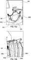
- Figure 10a is a representation of an alternative embodiment of an inflatable element 630 installed on a structure 600 in a deflated (retracted) configuration.
- Figure 10b is a representation of the installed inflatable element 630 of Figure 10a , in an inflated (pressurised) configuration.
- each inflatable section 640a, 640b, 640c, 640d is adhered to an adjacent inflatable section 640a, 640b, 640c, 640d.
- This provides an alternative to the basket 510 of Figure 9 .
- an innermost inflatable section 640a of the inflatable element 630 e.g. the inflatable section 640a closest to the structure 600 in use, is adhered to a frame 650.
- the frame 650 is configured to be directly coupled to corresponding supports or centralizers 660a, 660b.
- the frame 650 is bolted to the corresponding supports or centralizers 660a, 660b.
- the frame 650 may be adhered, glued, welded, fused or otherwise attached to the corresponding supports or centralizers 660a, 660b or to another portion of the structure 600.
- an outermost inflatable section 640d of the inflatable element 630 comprises a protective coating 670.
- the protective coating may be an insulating coating, e.g. formed from an electrically insulating material.
- an innermost inflatable section 640a of the inflatable element 630 comprises a protective coating (not shown).
- the protective coating may be an insulating coating, e.g. formed from an electrically insulating material.
- FIG 11 is a diagram showing a system, generally denoted 700, for stabilizing and/or lifting and/or separating a first structure relative to a second structure according to an embodiment of the invention.
- the system comprises a plurality of inflatable elements 730a, 730b, 760c, 730d for disposing between the first structure and the second structure.
- each inflatable element 730a, 730b, 760c, 730d comprises four inflatable sections.
- the first structure is a jacket 750 for an off-shore wind turbine.
- Each inflatable element 730a, 730b, 760c, 730d is connected to a corresponding hose 770a, 770b, 770c, 770d.
- Each hose is connected - at surface - to an arrangement or means for controlling and determining a fluid pressure in the inflatable elements, and an arrangement or means for measuring a volume of fluid used to inflate the inflatable elements, as will be described in more detail with reference to Figure 12 .
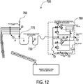
- Figure 12 shows a magnified view of a portion of the diagram of Figure 11 .
- Figure 12 shows a portion of the system 700 that is located at surface. Operation of the system is now described with reference to Figures 13, 14 and 15 , which provide example data embodying characteristics of the inflatable elements 730a, 730b, 730c, 730d.
- valves V1, V2, V3, V4, P-A and P-B are disposed on the jacket 750, e.g. topside on the jacket 750.
- Further components of the system 700 are disposed in a container 780 disposed on a support vessel 790. That is, the arrangement or means for controlling and determining a fluid pressure in the inflatable elements 730a, 730b, 730c, 730d, and the arrangement or means for measuring a volume of fluid used to inflate the inflatable elements 730a, 730b, 730c, 730d, are disposed in the container 780.
- the container 780 may be disposed elsewhere on the support vessel 790, i.e. not in the container 780, and/or on the jacket 750, e.g. topside the jacket.
- valves C-A, C-B, C-C, C-D, C-E, C-F, C-Y and CZ are disposed in the container 780 on the support vessel 790.
- a hose 720 provides a connection between the container 780 and the jacket 750.
- an initial configuration of each valve e.g. a configuration of each valve when the operation of stabilizing the jacket 750 relative to a second structure such as a foundation pile, is closed. That is, all of valves V1, V2, V3, V4, P-A, P-B, C-A, C-B, C-C, C-D, C-E, C-F, C-Y and CZ are initially closed, thus inhibiting a flow of fluid.
- a pressure in the inflatable elements 730a, 730b, 730c, 730d may be set to a pressure level below a default pressure, e.g. below atmospheric pressure, or an otherwise naturally occurring pressure at a depth of installation of the inflatable elements. That is, fluid in the inflatable elements 730a, 730b, 730c, 730d may be pumped from the inflatable elements 730a, 730b, 730c, 730d to reduce the pressure for purposes of testing the integrity of the system.
- a pressure at valves V1 - V4 may be a relatively low pressure as an initial condition.
- the integrity of the system 700, and in particular the inflatable elements 730a, 730b, 730c, 730d is tested by installing a vacuum gauge (not shown) outboard of valve P-B, and subsequently opening valve P-B. Then, each of valves V-1 to V-4 will be opened and closed in turn, and the pressure on the vacuum gauge recorded. If the pressure on the vacuum gauge is within a predefined range, or below a predefined threshold, e.g. the measured pressure substantially corresponds to the previously defined pressure level below a default pressure, then the inflatable elements 730a, 730b, 730c, 730d are maintaining a pressure level, and thus are of adequate integrity e.g. are adequately fluid tight.
- the next step in the process is to ensure that the hose 720 which provides a connection between the container 780 and the jacket 750 is filled.
- valves C-A, C-F and P-A are opened.
- An air operated fill pump is started to flush water through the hose until water is discharged from the hose, e.g. over the side of the platform, thus ensuring the hose contains no entrained air.
- the valve P-B on the platform is then closed.
- the first stage of inflating/pressurising the inflatable elements 730a, 730b, 730c, 730d is to pressurise each inflatable element 730a, 730b, 730c, 730d separately to a predefined pressure level.
- the defined pressure level is 1 MPa.
- the predefined pressure level is selected based on determined characteristics of the inflatable elements 730a, 730b, 730c, 730d. That is, at the predefined pressure level, e.g. 1MPa, the inflatable elements 730a, 730b, 730c, 730d will have adequately expanded to fill a gap between a surface of the jacket 750 and the structure relative to which the jacket 750 is to be stabilized.
- each inflatable element 730a, 730b, 730c, 730d the following sequence is carried out.
- valve P-B is opened to observe an adequate flow of fluid from the jacket topsides manifold to which valve P-B is communicably coupled.
- valve P-B is temporarily closed, and a pressure gauge 765 is fitted, directly or indirectly via a jacket topside manifold, to valve P-B or to an output of valve P-B. Valve P-B is subsequently reopened. Thus, a pressure at valve P-B can be read from the pressure gauge 765.
- a flow meter is calibrated by resetting the flow meter, e.g. setting a measurement of accumulated fluid flow to zero. Then, valve V1 is opened.
- Valves V1, V2, V3 and V4 are needle valves.
- valve V-1 is opened slowly.
- the flow meter 775 is shown topside the jacket, and in a fluid path to each of the inflatable elements. It will be appreciated that, in other embodiments of the invention, the flow meter 775 may be disposed at other, different locations within the system. For example, the flow meter may be coupled to the hose 720, or disposed on the support vessel, such as within the container 780.
- Fluid is then pumped into the first inflatable element 730a via valve V-1.
- valve V-1 When the defined pressure level, e.g. 1MPa, is established in the first inflatable element 730a, valve V-1 is closed. A volume of fluid required to establish the defined pressure level is recorded as a first measurement.
- valve V-2 is opened.
- valve V-2 is opened slowly.
- Fluid is then pumped into the second inflatable element 730b via valve V-2.
- valve V-2 When the defined pressure level, e.g. 1MPa, is established in the second inflatable element 730b, valve V-2 is closed. A volume of fluid required to establish the defined pressure level is recorded as a second measurement.
- valve V-3 is opened.
- valve V-3 is opened slowly.
- Fluid is then pumped into the third inflatable element 730c via valve V-3.
- valve V-3 When the defined pressure level, e.g. 1MPa, is established in the third inflatable element 730c, valve V-3 is closed. A volume of fluid required to establish the defined pressure level is recorded as a third measurement.
- valve V-4 is opened.
- valve V-4 is opened slowly.
- Fluid is then pumped into the fourth inflatable element 730d via valve V-2.
- valve V-4 is closed.
- a volume of fluid required to establish the defined pressure level is recorded as a fourth measurement.
- Example first characteristics of an inflatable element are show in Figure 13 .
- the first characteristic is a relationship between a size of the gap and a volume of fluid required to inflate the inflatable element to the defined pressure level.
- Figure 13 shows a volume of fluid required to inflate an inflatable element to a pressure of 1 MPa for a range of sizes of gap.
- the 'gap' refers to a space between the first and second structures, e.g. the jacket and the structure to which the jacket is stabilized.
- the inflatable element is disposed and inflated in the gap.
- a size of the gap into which an inflatable element is inflated to a defined pressure level can be derived from a volume of fluid required to inflate the inflatable element.
- a fill volume of 50 Litres corresponds to a gap of 0.3 metres.
- the first characteristic may be determined by means of simulation and/or testing of the inflatable element, or an equivalent or similar inflatable element. Such testing and/or simulation may typically take place on-shore.
- a size of the gap into which the first inflatable element 730a is disposed can be determined. Similar determinations can be made for the second, third and fourth inflatable elements 730b, 730c, 730d.
- a next step is to further pressurise each inflatable element 730a, 730b, 730c, 730d to provide a stabilizing force to be jacket.
- each inflatable element 730a, 730b, 730c, 730d is pressurized to a defined second pressure level to provide a desired loading to the structures to be stabilized.
- the defined second pressure level is determined based on the determined size of the gap and further characteristics of each inflatable element 730a, 730b, 730c, 730d.
- each inflatable element 730a, 730b, 730c, 730d is initially inflated/pressurised to a third pressure level, the third pressure level being substantially greater than the second pressure level; and subsequently deflated to the second pressure level. In this manner, maximum deformation of a surface of the inflatable element can be achieved, thus increasing a load-distributing surface area of the inflatable element.
- Example second characteristics of an inflatable element are show in Figure 14 .
- the second characteristic is a relationship between a size of the gap and a pressure required in the inflatable element to provide a stabilizing force of 830kN. That is, continuing with the previous example and based on the characteristics of the inflatable element shown in Figure 13 , in a gap determined to be 0.3m a pressure in each inflatable element would have to be increased to approximately 7MPa for the inflatable element to provide a stabilizing force of 830kN.
- the pressure regulator (C-Z) is set to the required pressure to establish 830kN force. Then, the air operated pump is started, with the with the pressure regulator (C-Z) set to establish an 830kN force. Then, valve V1 is opened - preferably slowly - to allow fluid to be pumped into the first inflatable element 730a until an 830kN force is provided by the inflatable element. A volume of fluid required to achieve the 830kN force is measured, and logged.
- a volume of fluid outside predetermined threshold e.g. an excessively high or low volume of fluid, may be used as an indication of a fault in the system. Valve V-1 is then closed.
- Example third characteristics of an inflatable element are show in Figure 15 .
- the third characteristic is a relationship between a size of the gap and a pressure required in the inflatable element to reduce the stabilizing force of 830kN to 450kN. That is, continuing with the previous example and based on the characteristics of the inflatable element shown in Figure 14 , in a gap determined to be 0.3m a pressure in each inflatable element would have to be decreased from 7MPa to 4MPa for the inflatable element to provide a stabilizing force of 450kN.
- the process for reducing the pressure is as follows.
- Valve P-A is opened. Then, each of valves V-1, V-2, V-3 and V-4 are individually opened, preferably slowly, to relieve the pressure to the 4MPa, and then closed again to sustain the pressure at 4MPa.
- An optional further step may remove equipment from the jacket topside.
- the optionally further step may comprise closing valves P-A and P-B, removing the pressure gauge, and disconnecting hose 720.
- Figure 16a shows a schematic representation of a cross-sectional view of a schematic representation of inflatable elements in use for stabilizing a concentrically arranged first structure 800 relative to a second structure 810.
- Four inflatable elements 830a, 830b, 830c, 830d provide a stabilizing force between the first structure 800 relative to a second structure 810. Due to the concentric arrangement of the first and second structures, a pressure required in each of the four inflatable elements 830a, 830b, 830c, 830d is substantially the same.
- Figure 16b is a schematic representation of an alternative arrangement, wherein inflatable elements 830a, 830b, 830c, 830d are provided for stabilizing a non-concentrically arranged first structure 800 relative to a second structure 810.
- a larger fluid pressure is required in first inflatable element 830a compared to third inflatable element 830c to provide equal and opposite forces acting on the structures 800, 810.
- first inflatable element 830a fills a gap of 0.4m, and by adhering to the example data provided in Figure 15
- a fluid pressure of approximately 5MPa is required to provide a stabilizing force of 450kN.
- a fluid pressure of approximately 3.1MPa is required to provide a stabilizing force of 450kN.
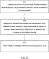
- Figure 17 shows a flow diagram of a method of stabilizing and/or lifting and/or separating a first structure relative to a second structure.
- the method comprises a second step 920.
- a second pressure level required to provide a desired stabilizing and/or lifting and/or separating force to be applied to the structures by the inflatable element is determined.
- the method comprises a third step 930.
- the inflatable element is further inflated to the second pressure level.
- embodiments of the present invention may provide a beneficial or advantageously (low) input force (pressure) to inflatable element expansion ratio or "stroke”. It will further be appreciated that while the disclosed embodiments show rectilinear inflatable members, other shapes (closed shapes) of inflatable members may be envisaged, e.g. having three or more corners, wherein at least one of the corners comprises a concave portion.
Landscapes
- Engineering & Computer Science (AREA)
- General Engineering & Computer Science (AREA)
- Mechanical Engineering (AREA)
- Structural Engineering (AREA)
- Civil Engineering (AREA)
- General Life Sciences & Earth Sciences (AREA)
- Life Sciences & Earth Sciences (AREA)
- Architecture (AREA)
- Chemical & Material Sciences (AREA)
- Combustion & Propulsion (AREA)
- Ocean & Marine Engineering (AREA)
- Wind Motors (AREA)
- Actuator (AREA)
Applications Claiming Priority (1)
| Application Number | Priority Date | Filing Date | Title |
|---|---|---|---|
| GB1912229.0A GB2590051B (en) | 2019-08-26 | 2019-08-26 | Stablization methods and system |
Publications (2)
| Publication Number | Publication Date |
|---|---|
| EP3786367A2 true EP3786367A2 (fr) | 2021-03-03 |
| EP3786367A3 EP3786367A3 (fr) | 2021-06-09 |
Family
ID=68108825
Family Applications (1)
| Application Number | Title | Priority Date | Filing Date |
|---|---|---|---|
| EP20192722.5A Pending EP3786367A3 (fr) | 2019-08-26 | 2020-08-25 | Procédés et système de stabilisation |
Country Status (2)
| Country | Link |
|---|---|
| EP (1) | EP3786367A3 (fr) |
| GB (1) | GB2590051B (fr) |
Cited By (2)
| Publication number | Priority date | Publication date | Assignee | Title |
|---|---|---|---|---|
| EP3848511A1 (fr) * | 2019-10-03 | 2021-07-14 | Planet 42 Limited | Appareil de support |
| WO2025252917A1 (fr) * | 2024-06-06 | 2025-12-11 | Seaway 7 Engineering B.V. | Liaison de sections de structures de treillis divisées |
Family Cites Families (9)
| Publication number | Priority date | Publication date | Assignee | Title |
|---|---|---|---|---|
| US4063427A (en) * | 1975-08-04 | 1977-12-20 | Lynes, Inc. | Seal arrangement and flow control means therefor |
| US4063421A (en) * | 1975-08-04 | 1977-12-20 | Lynes, Inc. | Grouting system and arrangement for offshore structure |
| US4050731A (en) * | 1976-01-26 | 1977-09-27 | Lynes, Inc. | Shifting apparatus |
| US4077224A (en) * | 1976-05-13 | 1978-03-07 | Lynes, Inc. | Method and apparatus for grouting an offshore structure |
| US4140426A (en) * | 1977-10-21 | 1979-02-20 | Halliburton Company | System for inflating packers and placing grout through one line |
| EP2834423B1 (fr) * | 2012-03-29 | 2019-10-23 | W3g Piling Noise Mitigation Ltd. | Structures en mer, appareil et procédés associés |
| NL2013886B1 (en) * | 2014-11-27 | 2016-10-11 | Ihc Holland Ie Bv | Temporarily coupling between jacket and pile. |
| GB201602227D0 (en) * | 2016-02-08 | 2016-03-23 | West Alan And W3G Marine Ltd And Whyte Charles And Giles John S | Method and apparatus for securing a foundation before grouting operations |
| GB2576877B (en) * | 2018-08-31 | 2020-09-16 | Planet 42 Ltd | Packer gripper element |
-
2019
- 2019-08-26 GB GB1912229.0A patent/GB2590051B/en active Active
-
2020
- 2020-08-25 EP EP20192722.5A patent/EP3786367A3/fr active Pending
Cited By (2)
| Publication number | Priority date | Publication date | Assignee | Title |
|---|---|---|---|---|
| EP3848511A1 (fr) * | 2019-10-03 | 2021-07-14 | Planet 42 Limited | Appareil de support |
| WO2025252917A1 (fr) * | 2024-06-06 | 2025-12-11 | Seaway 7 Engineering B.V. | Liaison de sections de structures de treillis divisées |
Also Published As
| Publication number | Publication date |
|---|---|
| EP3786367A3 (fr) | 2021-06-09 |
| GB201912229D0 (en) | 2019-10-09 |
| GB2590051A (en) | 2021-06-23 |
| GB2590051B (en) | 2023-10-11 |
Similar Documents
| Publication | Publication Date | Title |
|---|---|---|
| US9845654B2 (en) | Subsea support | |
| EP3786367A2 (fr) | Procédés et système de stabilisation | |
| US10151151B2 (en) | Riser deflection mitigation | |
| US5232202A (en) | Tank lifting methods | |
| US20250179753A1 (en) | Method of installing a monopile in a seabed using a transportation barge or vessel | |
| US8727011B2 (en) | Wellhead test tool and method | |
| EP2981653B1 (fr) | Procédé permettant de lever une plate-forme marine | |
| EP3844346B1 (fr) | Barrage | |
| Rickman et al. | Offshore construction of grouted driven pile foundations | |
| WO2019102184A1 (fr) | Procédé et appareil pour supporter une tête de puits | |
| AP579A (en) | Offshore well saving apparatus and method. | |
| KR20150096748A (ko) | 부유 시추 플랫폼의 시추 라이저의 신속한 분리 시스템 및 방법 | |
| US20130230357A1 (en) | Riser Protection Structures | |
| US4279546A (en) | Grout seal premature inflation protective system | |
| US8833462B2 (en) | Method and system for installing subsea well trees | |
| US20140262310A1 (en) | Riser tension augmentation | |
| WO2016014413A1 (fr) | Dispositifs de protection de piliers pour plate-formes auto-élévatrices | |
| GB2136036A (en) | Improvements in and Relating to Levelling a Subsea Template | |
| CA1298712C (fr) | Structure amovible a fondation inferieure | |
| KR20150096236A (ko) | 테스트 파이프 변형 장치 및 이를 이용한 bop 테스트 장치 | |
| Harris et al. | Drilling in 1,300 Feet of WaterSanta Barbara Channel, California | |
| HK1221270B (en) | Method for elevating a marine platform | |
| GB2511716A (en) | A sleeve for collecting contaminants |
Legal Events
| Date | Code | Title | Description |
|---|---|---|---|
| PUAI | Public reference made under article 153(3) epc to a published international application that has entered the european phase |
Free format text: ORIGINAL CODE: 0009012 |
|
| STAA | Information on the status of an ep patent application or granted ep patent |
Free format text: STATUS: REQUEST FOR EXAMINATION WAS MADE |
|
| 17P | Request for examination filed |
Effective date: 20200825 |
|
| AK | Designated contracting states |
Kind code of ref document: A2 Designated state(s): AL AT BE BG CH CY CZ DE DK EE ES FI FR GB GR HR HU IE IS IT LI LT LU LV MC MK MT NL NO PL PT RO RS SE SI SK SM TR |
|
| AX | Request for extension of the european patent |
Extension state: BA ME |
|
| PUAL | Search report despatched |
Free format text: ORIGINAL CODE: 0009013 |
|
| AK | Designated contracting states |
Kind code of ref document: A3 Designated state(s): AL AT BE BG CH CY CZ DE DK EE ES FI FR GB GR HR HU IE IS IT LI LT LU LV MC MK MT NL NO PL PT RO RS SE SI SK SM TR |
|
| RIC1 | Information provided on ipc code assigned before grant |
Ipc: E02B 17/02 20060101AFI20210503BHEP Ipc: E02B 17/04 20060101ALI20210503BHEP Ipc: E02B 17/00 20060101ALN20210503BHEP |
|
| STAA | Information on the status of an ep patent application or granted ep patent |
Free format text: STATUS: EXAMINATION IS IN PROGRESS |
|
| RIN1 | Information on inventor provided before grant (corrected) |
Inventor name: WEST, ALAN WILLIAM HENRY Inventor name: WHYTE, CHARLES JOHN Inventor name: GILES, JOHN STEPHEN |
|
| 17Q | First examination report despatched |
Effective date: 20230823 |
|
| GRAP | Despatch of communication of intention to grant a patent |
Free format text: ORIGINAL CODE: EPIDOSNIGR1 |
|
| STAA | Information on the status of an ep patent application or granted ep patent |
Free format text: STATUS: GRANT OF PATENT IS INTENDED |
|
| INTG | Intention to grant announced |
Effective date: 20250424 |
|
| RIC1 | Information provided on ipc code assigned before grant |
Ipc: E02B 17/00 20060101ALN20250415BHEP Ipc: E02B 17/04 20060101ALI20250415BHEP Ipc: E02B 17/02 20060101AFI20250415BHEP |
|
| GRAS | Grant fee paid |
Free format text: ORIGINAL CODE: EPIDOSNIGR3 |