EP3786393A1 - Module mobile de hissage de tours téléscopiques et procédé de hissage de tours téléscopiques - Google Patents
Module mobile de hissage de tours téléscopiques et procédé de hissage de tours téléscopiques Download PDFInfo
- Publication number
- EP3786393A1 EP3786393A1 EP19791961.6A EP19791961A EP3786393A1 EP 3786393 A1 EP3786393 A1 EP 3786393A1 EP 19791961 A EP19791961 A EP 19791961A EP 3786393 A1 EP3786393 A1 EP 3786393A1
- Authority
- EP
- European Patent Office
- Prior art keywords
- hoisting
- tower
- cable
- movable module
- section
- Prior art date
- Legal status (The legal status is an assumption and is not a legal conclusion. Google has not performed a legal analysis and makes no representation as to the accuracy of the status listed.)
- Granted
Links
Images


Classifications
-
- E—FIXED CONSTRUCTIONS
- E04—BUILDING
- E04H—BUILDINGS OR LIKE STRUCTURES FOR PARTICULAR PURPOSES; SWIMMING OR SPLASH BATHS OR POOLS; MASTS; FENCING; TENTS OR CANOPIES, IN GENERAL
- E04H12/00—Towers; Masts or poles; Chimney stacks; Water-towers; Methods of erecting such structures
- E04H12/34—Arrangements for erecting or lowering towers, masts, poles, chimney stacks, or the like
-
- E—FIXED CONSTRUCTIONS
- E04—BUILDING
- E04H—BUILDINGS OR LIKE STRUCTURES FOR PARTICULAR PURPOSES; SWIMMING OR SPLASH BATHS OR POOLS; MASTS; FENCING; TENTS OR CANOPIES, IN GENERAL
- E04H12/00—Towers; Masts or poles; Chimney stacks; Water-towers; Methods of erecting such structures
- E04H12/18—Towers; Masts or poles; Chimney stacks; Water-towers; Methods of erecting such structures movable or with movable sections, e.g. rotatable or telescopic
- E04H12/182—Towers; Masts or poles; Chimney stacks; Water-towers; Methods of erecting such structures movable or with movable sections, e.g. rotatable or telescopic telescopic
-
- E—FIXED CONSTRUCTIONS
- E04—BUILDING
- E04H—BUILDINGS OR LIKE STRUCTURES FOR PARTICULAR PURPOSES; SWIMMING OR SPLASH BATHS OR POOLS; MASTS; FENCING; TENTS OR CANOPIES, IN GENERAL
- E04H12/00—Towers; Masts or poles; Chimney stacks; Water-towers; Methods of erecting such structures
- E04H12/34—Arrangements for erecting or lowering towers, masts, poles, chimney stacks, or the like
- E04H12/344—Arrangements for lifting tower sections for placing additional sections under them
-
- B—PERFORMING OPERATIONS; TRANSPORTING
- B66—HOISTING; LIFTING; HAULING
- B66F—HOISTING, LIFTING, HAULING OR PUSHING, NOT OTHERWISE PROVIDED FOR, e.g. DEVICES WHICH APPLY A LIFTING OR PUSHING FORCE DIRECTLY TO THE SURFACE OF A LOAD
- B66F3/00—Devices, e.g. jacks, adapted for uninterrupted lifting of loads
- B66F3/24—Devices, e.g. jacks, adapted for uninterrupted lifting of loads fluid-pressure operated
- B66F3/242—Devices, e.g. jacks, adapted for uninterrupted lifting of loads fluid-pressure operated suspended jacks
-
- E—FIXED CONSTRUCTIONS
- E04—BUILDING
- E04H—BUILDINGS OR LIKE STRUCTURES FOR PARTICULAR PURPOSES; SWIMMING OR SPLASH BATHS OR POOLS; MASTS; FENCING; TENTS OR CANOPIES, IN GENERAL
- E04H12/00—Towers; Masts or poles; Chimney stacks; Water-towers; Methods of erecting such structures
- E04H12/34—Arrangements for erecting or lowering towers, masts, poles, chimney stacks, or the like
- E04H12/342—Arrangements for stacking tower sections on top of each other
-
- F—MECHANICAL ENGINEERING; LIGHTING; HEATING; WEAPONS; BLASTING
- F03—MACHINES OR ENGINES FOR LIQUIDS; WIND, SPRING, OR WEIGHT MOTORS; PRODUCING MECHANICAL POWER OR A REACTIVE PROPULSIVE THRUST, NOT OTHERWISE PROVIDED FOR
- F03D—WIND MOTORS
- F03D13/00—Assembly, mounting or commissioning of wind motors; Arrangements specially adapted for transporting wind motor components
- F03D13/10—Assembly of wind motors; Arrangements for erecting wind motors
-
- F—MECHANICAL ENGINEERING; LIGHTING; HEATING; WEAPONS; BLASTING
- F03—MACHINES OR ENGINES FOR LIQUIDS; WIND, SPRING, OR WEIGHT MOTORS; PRODUCING MECHANICAL POWER OR A REACTIVE PROPULSIVE THRUST, NOT OTHERWISE PROVIDED FOR
- F03D—WIND MOTORS
- F03D13/00—Assembly, mounting or commissioning of wind motors; Arrangements specially adapted for transporting wind motor components
- F03D13/20—Arrangements for mounting or supporting wind motors; Masts or towers for wind motors
-
- E—FIXED CONSTRUCTIONS
- E04—BUILDING
- E04H—BUILDINGS OR LIKE STRUCTURES FOR PARTICULAR PURPOSES; SWIMMING OR SPLASH BATHS OR POOLS; MASTS; FENCING; TENTS OR CANOPIES, IN GENERAL
- E04H12/00—Towers; Masts or poles; Chimney stacks; Water-towers; Methods of erecting such structures
- E04H12/02—Structures made of specified materials
- E04H12/08—Structures made of specified materials of metal
-
- E—FIXED CONSTRUCTIONS
- E04—BUILDING
- E04H—BUILDINGS OR LIKE STRUCTURES FOR PARTICULAR PURPOSES; SWIMMING OR SPLASH BATHS OR POOLS; MASTS; FENCING; TENTS OR CANOPIES, IN GENERAL
- E04H12/00—Towers; Masts or poles; Chimney stacks; Water-towers; Methods of erecting such structures
- E04H12/02—Structures made of specified materials
- E04H12/12—Structures made of specified materials of concrete or other stone-like material, with or without internal or external reinforcements, e.g. with metal coverings, with permanent form elements
-
- Y—GENERAL TAGGING OF NEW TECHNOLOGICAL DEVELOPMENTS; GENERAL TAGGING OF CROSS-SECTIONAL TECHNOLOGIES SPANNING OVER SEVERAL SECTIONS OF THE IPC; TECHNICAL SUBJECTS COVERED BY FORMER USPC CROSS-REFERENCE ART COLLECTIONS [XRACs] AND DIGESTS
- Y02—TECHNOLOGIES OR APPLICATIONS FOR MITIGATION OR ADAPTATION AGAINST CLIMATE CHANGE
- Y02E—REDUCTION OF GREENHOUSE GAS [GHG] EMISSIONS, RELATED TO ENERGY GENERATION, TRANSMISSION OR DISTRIBUTION
- Y02E10/00—Energy generation through renewable energy sources
- Y02E10/70—Wind energy
- Y02E10/72—Wind turbines with rotation axis in wind direction
-
- Y—GENERAL TAGGING OF NEW TECHNOLOGICAL DEVELOPMENTS; GENERAL TAGGING OF CROSS-SECTIONAL TECHNOLOGIES SPANNING OVER SEVERAL SECTIONS OF THE IPC; TECHNICAL SUBJECTS COVERED BY FORMER USPC CROSS-REFERENCE ART COLLECTIONS [XRACs] AND DIGESTS
- Y02—TECHNOLOGIES OR APPLICATIONS FOR MITIGATION OR ADAPTATION AGAINST CLIMATE CHANGE
- Y02E—REDUCTION OF GREENHOUSE GAS [GHG] EMISSIONS, RELATED TO ENERGY GENERATION, TRANSMISSION OR DISTRIBUTION
- Y02E10/00—Energy generation through renewable energy sources
- Y02E10/70—Wind energy
- Y02E10/728—Onshore wind turbines
Definitions
- the present invention relates to a movable module for hoisting telescopic towers, for example concrete and/or metal telescopic towers.
- telescopic towers for example concrete and/or metal telescopic towers.
- the primary sector of application thereof is the construction industry, particularly in assembling towers, and more specifically telescopic towers.
- High-rise tower structures such as those commonly used for supporting wind turbines are often constructed by means of prefabricated reinforced and/or prestressed concrete segments which are subsequently transported to the installation site where they are hoisted by means of a crane and assembled in their final position.
- each vertical section is generally assembled from connected segments.
- the lower section of the assembly tower is erected first, and after that successive sections are hoisted onto the lower section, being lifted to their final position using a crane.
- the sections are usually pre-assembled at ground-level, although, alternatively, the segments of a particular section can be hoisted separately and then be assembled in the upper part of the previous section.
- the upper section is hoisted such that it supports the assembly formed by the generator and the rotor of the wind turbine.
- Wind turbine towers can reach heights in the order of 100-150 m, supporting generation units capable of producing power in the order of one to tens of megawatts.
- Conventional techniques for constructing these towers require the segments of the tower to be lifted using large cranes, which must present hoisting heights of at least the total height the structure of the tower itself.
- the generator unit which may weigh up to 200 tons, also has to be lifted to its final position at the upper part of the structure.
- Patent application WO 2009/010771 A2 describes a method of hoisting a telescopic tower in which several prefabricated telescopic sections of a tower are horizontally assembled at the ground-level. Said telescopic sections are hoisted together in the vertical position, either by means of a crane or by lifting each section against its outer neighboring section, using an arrangement of supporting elements and extendable connectors such as powered jacks.
- each vertical section is nested in the contiguous outer section thereof, such that the wall elements form an additional supporting wall covering the inner surface of each outer tower section.
- the method of hoisting a tower described in WO 2009/010771 A2 suffers, however, from the following drawbacks.
- the method is based on the support of a flange in the lower part of each tower section, on a projection in the lower part of the inner section. This implies that the sections must be hoisted in a specific order, since each successive inner section rests on its outer neighboring section.
- the method of WO 2009/010771 A2 is excessively toilsome, since it implies the construction and subsequent dismantling of an entire inner wall structure (which is almost as large as the tower itself), which may have a serious impact on the tower construction speed.
- the described method is only suitable for structures in which all the walls of all the sections of the tower are substantially parallel.
- a fitting step is performed through a plurality of jacking tendons between upper and lower points of said telescopic sections, where tension is applied to said tendons by means of hydraulic jacks, such that the weight of each section is supported at the upper jacking points of the contiguous section, and the sections are raised as tensioning is performed on the mentioned jacking tendons.
- the alternative described in WO 2011/006526 A1 allows the processes of installing conventional telescopic towers to be improved, it still presents problems left unsolved in the state of the art fundamentally relating to the complexity of the pre-installation steps and the execution times for hoisting tower sections.
- the invention described in said application comprises a first installation phase for installing the tendons in each of the telescopic sections, and later phases in which the hydraulic jacks are connected to and released from the cables in order to perform the various hoisting operations for completely raising the tower.
- this implies the necessary delay in pre-installation and hoisting times, since a prior task of placing the loose cables and a subsequent task of connecting the hydraulic jacks to said cables are necessary.
- the hydraulic jacks must be released from the cables and connected to others, with the corresponding increase in work, time, and risk, as said jacking points are sensitive and bear enormous responsibility.
- the objective of the present invention is to provide a movable module and a method of hoisting which allows the sections of the tower to be assembled without a crane, or with the use of a small crane having a size substantially equal to the size of a tower section, where said method comprises hoisting the tower sections much more quickly and more efficiently than with the known techniques, which further allows the use of tower sections having non-parallel walls.
- the present invention provides a movable module for hoisting telescopic towers and the corresponding method of hoisting telescopic towers, said towers preferably being concrete and/or metal towers, which allows the process for hoisting them to be optimized.
- Another objective of the present invention is to also provide a system which allows the number of operations to be performed during said method to be reduced, thereby avoiding more complicated processes, and reducing costs, times, and risks.
- the operation time is furthermore reduced, and the entire process is streamlined, which at the same time allows the time for hoisting the towers to be reduced, which represents important operative and economic savings.
- the present invention qualitatively improves the capacity and ease for reclaiming and reusing hoisting means and equipment in the different towers of a farm.
- a movable module for hoisting telescopic towers preferably wind turbine towers, an ascending section of the tower being hoisted in relation to a supporting section of the tower immediately outside
- said movable module advantageously comprises:
- the movable module is temporarily fixed to the head of the supporting section, and the grouping means are temporarily fixed to the base of the ascending section.
- the objective of the invention is performed by means of a movable module for hoisting telescopic towers and a method of hoisting telescopic towers according to the claims herein.
- the module herein described thereby allows, during its application, the steps of positioning the hoisting cables and the raising of each section to be performed in a single step, optimally reusing the cables for different hoisting operations and without implementing any of connection/disconnection operation between the hoisting cables and the hoisting jacks.
- the movable module can be easily moved so as to be placed in the different positions established for hoisting the different sections of the tower. Furthermore, said module moves at all times as a single part, that is, only one movement between hoisting phases is necessary, greatly improving streamlining and cost. This feature differs entirely from the solutions known in the current state of the art, where the elements must be mobilized one by one, which implies a significant advantage of the present invention over the current state of the art.
- Said movable module may comprise also at least one cable guiding structure which allows guiding the hoisting cable protruding from the upper part of the hydraulic jack.
- the module may also comprise at least one cable take-up element which can furthermore be arranged in a raised position, such that the circulation of workers is facilitated.
- this position of the take-up element largely facilitates the operations to be performed, which allows the free circulation of operators and represents another considerable advantage of the invention by reducing the dimensions of the work platform and/or avoiding the installation thereof.
- Said take-up element can be in the form of a drum or recoiler, or any similar or equivalent element known in the art.
- the take-up element can be passive or active, incorporating a motor or the like to collaborate in the deployment and/or drawing-in of the hoisting cable.
- the movable module may also comprise a guiding element in contact with the ascending section, which is preferably a sliding or rolling contact, and/or contact by means of caterpillar track-type elements.
- the method of hoisting telescopic towers described above may comprise the hoisting of at least two different sections of the tower, the main steps of the method being repeated for hoisting different sections of the tower.
- said method may be characterized in that the innermost section of the tower is initially hoisted, and hoisting is continued from the innermost to the outermost section.
- the heads of different tower sections to be hoisted can be positioned at considerably the same level.
- the movable module of the invention can thereby be moved radially for the positioning thereof at the heads of the different tower sections, through at least one horizontal movement means, for example one or more rails.
- said method may be characterized in that the described grouping means may be reclaimable and comprise:
- Said wedge plate may comprise a protective element allowing it to run through the conduits of the different sections intended for housing the hoisting cables. Likewise, said protective element of the wedge plate may be pointed to prevent jamming.
- Movable hoisting module (2) Hydraulic jack (2') Frame (3) Hoisting cable (3') Strands making up the hoisting cable (4) Grouping means (5) Cable guiding structure (6) Cable take-up element (7) Guiding element (8) Horizontal movement means (9) Screw-in wedge plate (10) First screw-in distribution plate (11) Second screw-in distribution plate (12) Protective element (100) Telescopic tower (101) Wind turbine tower (200) Tower sections (202) First adjacent section (203) Second adjacent section (210) Ascending section (211) Supporting section (300) Work platform
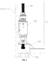
- Figures 1-7 illustrate different views of the movable module (1) of the invention for hoisting telescopic towers (100), preferably wind turbine towers (101).
- the movable module (1) comprises a hydraulic jack (2), a hoisting cable (3) pre-installed through the hydraulic jack (2) and which remains connected to said jack throughout the performance of the method of hoisting the telescopic tower (100), and grouping means (4) arranged substantially at the free end of the hoisting cable (3).
- the hoisting cable (3) is formed by a plurality of strands (3') (see the schematic distribution thereof in Figure 6 ).
- the cable (3) goes through the hydraulic jack (2), such that the upper end thereof preferably protrudes from the upper part of the hydraulic jack (2), and its lower end protrudes from the lower part of the hydraulic jack (2) (see Figures 2-3 ), said hoisting cable (3) remaining connected to the hydraulic jack (2) throughout the performance of the method of hoisting the telescopic tower (100) (see, for example, Figure 5 ).
- the strands (3') are integrated in the hoisting cable (3) independently, that is, the strands (3') are not intertwined or mechanically connected, but rather are grouped together in a substantially parallel bundle.
- the movable module (1) of the invention also has grouping means (4) intended for preventing the strands (3') from crossing each other, as well as to facilitate threading the hoisting cable (3) through the head of a supporting section (211) and the base of an ascending section (210) (see said sections in Figure 5 ) of the telescopic tower (100).
- the hoisting cable (3) may, additionally and as shown in Figure 7 , have a pointed geometry for facilitating the guiding thereof through said sections (210, 211).
- the grouping means (4) are essentially positioned at the lower end of the hoisting cable (3), keeping all the strands (3') making up said hoisting cable (3) grouped together.
- the grouping means (4) contribute to keeping the strands (3') positioned so as to maintain the distribution thereof which is used both in the hydraulic jack (2) and at the lower end of the cable, furthermore being able to act as anchoring means for holding said position.
- the grouping means (4) can be detachable, being removable for adding anchoring means, and being added again at the lower end of the cable at a later time of the method of hoisting the tower (100).
- the movable hoisting module (1) of the invention allows a two-way movement of the hoisting cable (3) through the hydraulic jack (2), said hoisting cable (3) being able to both be extended in the essentially descending direction and be taken up in essentially the ascending direction.
- the mean diameter "D" of the hoisting cable (3) is less than 4 ⁇ d ⁇ (N) 1/2 , where "d” is the mean diameter of the strands (3') forming the hoisting cable (3) and "N” is the total number of strands (3'). This thereby achieves the hoisting cable (3) presenting suitable dimensions for going through the flanges of the sections (210, 211) of the telescopic tower (100).
- the movable module (1) of the invention preferably comprises a supporting frame (2') to which the lower part of the hydraulic jack (2) is fixed, and comprising a channel for the passage of the hoisting cable (3), the dimension of which allows housing the grouping means (4).
- the movable hoisting module (1) can adopt a transfer position in which the hoisting cable (3) is completely drawn in or taken up, and in which the lower end of the hoisting cable (3) and the grouping means (4) are housed in a channel of the frame (2').
- the movable module (1) may be transferred between hoisting operations or between towers, or even between farms, supported on its frame (2'). To that end, in the transfer position the cable (3) is prevented from protruding below the frame (2').
- the movable module (1) may comprise one or more jacking points (not shown in the figures) which allow suspending the module completely. Said jacking points are preferably positioned substantially on the vertical of the center of gravity of the movable module in its transfer position.
- the frame (2') may adopt a horizontal dimension such that the movable module (1) simply supported on said frame (2') is sufficiently stable against horizontal loads, which facilitates storage and transfer of the module (1), for example, between towers of the farm.
- the frame (2') comprises horizontal movement means (8) for facilitating the horizontal transfer of the movable module (1) for different hoisted.
- Said movement means (8) can be of any of the types known in the art for the movement of equipment, such as rails and/or rolling means, or elements for facilitating the sliding of the module (1). They may likewise incorporate or use pushing or pulling means for applying force to move the module (1) from one position to another (for example, from the head of one supporting section (211) to the next one).
- the movable module (1) further comprises one or more work platforms and/or equipment storage, preferably connected to the frame (2').
- the equipment that can be housed in the mentioned platforms is typically power pack-type systems (hydraulic pumps) or manifolds which allow hydraulically powering the jacks (2) and/or controlling their operation. They may also incorporate telecommunication means for facilitating the remote control of the movable module (1).
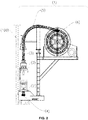
- FIG. 2 shows a preferred embodiment of the movable module (1) further comprising a cable guiding structure (5), which allows the guiding of the hoisting cable (3) protruding from the hydraulic jack (2).
- Said cable guiding structure (5) acts throughout the entire process of hoisting the sections of the telescopic tower (100), directing the cable to a cable take-up element (6) also comprised in the movable module (1).
- said cable take-up element (6) is arranged in a raised position, such that the circulation of workers on the corresponding work platform (300) during the process of hoisting the telescopic tower (100) is facilitated. The need to install a larger and therefore more expensive platform is thereby eliminated.
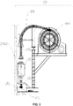
- Figure 3 depicts an embodiment of the movable module described in the present invention which additionally incorporates a guiding element (7) in contact with the ascending section (210).
- Said contact can preferably be a sliding or rolling contact, or contact by means of caterpillar track-type elements. Therefore, said guiding element may exert a force perpendicular to the structure for restricting possible inclinations of the sections of the telescopic tower (100) during the process of hoisting.
- Figure 4a shows a front view of another preferred embodiment of the invention.
- the movable module (1) comprises two hydraulic jacks (2) and the corresponding hoisting cables (3), cable guiding structures (5) for guiding said cables, and the cable take-up elements (6).
- this embodiment also comprises a guiding element (7) positioned between the two hydraulic jacks (2). This embodiment allows exerting a greater hoisting force if the sections to be hoisted require more powerful means, while at the same time optimizing the entire overall process of hoisting the telescopic tower.
- Figure 4b illustrates a plan view of a possible hoisting configuration of a telescopic tower with several integrated modules (1) arranged homogenously on the perimeter of the tower sections to be hoisted.
- the possible arrangement of the horizontal movement means (8) (for example, rails) comprised in the method and allowing the movement of the movable module (1) for the positioning thereof in each step of hoisting can be observed in this figure.
- Figure 5 depicts a possible embodiment of the method of hoisting same described in the present invention.
- Figure 5a shows a first hoisting step in which the movable module (1) is first positioned at the head of the supporting section (211), which in this case is the immediately adjacent section (202) and the hoisting cable (3) is fixed to the base of the ascending section (210), which in this case is the innermost section of the tower (201), by the grouping means (4) positioned at the base of said section to subsequently perform the hoisting thereof by means of taking up said cable.
- Figure 5b illustrates the base of the hoisted section (201) as a single part to the head of the following supporting section (211), which in this case is the immediately adjacent section (203).
- the movement is performed by lifting the module by means of cranes, although it can also be performed by sliding the module through the horizontal movement means (8).
- Figure 5d shows the following hoisting step where the hoisting cable (3) slides and is fixed to the base of the new ascending section (210).
- Figure 5e depicts a subsequent hoisting step in which the previously fixed sections (201, 202) are hoisted.
- Figure 5f shows the next step similar to the step depicted in Figure 5b , in which the hoisted sections (201, 202) are fixed to the supporting section (211).
- an advantage of the method of the invention is that it does not require any step of connecting and/or disconnecting between the hoisting cable (3) and the hydraulic jack (2), or any operation for placing loose cables.
- the movable module (1) itself is thereby capable of deploying the taken up cable (3) for placing it the hoisting position.
- Figure 6 illustrates an embodiment of the grouping means (4) described in the present invention, comprising a screw-in wedge plate (9), a first screw-in distribution plate that can be screwed into said wedge plate (10), and a second distribution plate (11) with a hole through which said wedge plate can pass.
- This configuration allows performing the method of hoisting same avoiding the placement of the wedge plate (9) in each hoisting phase, keeping the hoisting cable (3) threaded and connected to the hydraulic jack (2) throughout the entire method.
- Figure 7 shows a protective element (12) installed in the wedge plate (9) such that it is able to run through the conduits of the different sections intended for housing the hoisting cables (3). Furthermore, said protective element (12) may be pointed to prevent jamming in the conduits.
Landscapes
- Engineering & Computer Science (AREA)
- Architecture (AREA)
- Structural Engineering (AREA)
- Mechanical Engineering (AREA)
- Life Sciences & Earth Sciences (AREA)
- Civil Engineering (AREA)
- Sustainable Development (AREA)
- Sustainable Energy (AREA)
- Chemical & Material Sciences (AREA)
- Combustion & Propulsion (AREA)
- General Engineering & Computer Science (AREA)
- Geology (AREA)
- Wind Motors (AREA)
- Conveying And Assembling Of Building Elements In Situ (AREA)
- Types And Forms Of Lifts (AREA)
Applications Claiming Priority (2)
| Application Number | Priority Date | Filing Date | Title |
|---|---|---|---|
| ES201830404A ES2728789B2 (es) | 2018-04-25 | 2018-04-25 | Modulo movil para el izado de torres telescopicas y procedimiento de izado de torres telescopicas |
| PCT/ES2019/070272 WO2019207188A1 (fr) | 2018-04-25 | 2019-04-22 | Module mobile de hissage de tours téléscopiques et procédé de hissage de tours téléscopiques |
Publications (3)
| Publication Number | Publication Date |
|---|---|
| EP3786393A1 true EP3786393A1 (fr) | 2021-03-03 |
| EP3786393A4 EP3786393A4 (fr) | 2021-12-29 |
| EP3786393B1 EP3786393B1 (fr) | 2023-10-04 |
Family
ID=68290086
Family Applications (1)
| Application Number | Title | Priority Date | Filing Date |
|---|---|---|---|
| EP19791961.6A Active EP3786393B1 (fr) | 2018-04-25 | 2019-04-22 | Module mobile de hissage de tours téléscopiques et procédé de hissage de tours téléscopiques |
Country Status (6)
| Country | Link |
|---|---|
| US (1) | US20210222452A1 (fr) |
| EP (1) | EP3786393B1 (fr) |
| JP (1) | JP7325838B2 (fr) |
| CN (1) | CN112041522B (fr) |
| ES (1) | ES2728789B2 (fr) |
| WO (1) | WO2019207188A1 (fr) |
Families Citing this family (4)
| Publication number | Priority date | Publication date | Assignee | Title |
|---|---|---|---|---|
| CN113387283A (zh) * | 2021-07-08 | 2021-09-14 | 中建三局集团有限公司 | 一种用于顶部加减节塔机的顶升套架及塔机 |
| CN114204484B (zh) * | 2021-11-16 | 2024-01-05 | 重庆海装风电工程技术有限公司 | 一种风力发电机组动力电缆敷设方法 |
| US12529239B2 (en) | 2022-10-31 | 2026-01-20 | Ge Infrastructure Technology Llc | Wind turbine tower structure with stacked tower sections |
| US11952977B1 (en) | 2023-11-29 | 2024-04-09 | Donald Gehring | Telescopic wind turbine tower |
Family Cites Families (16)
| Publication number | Priority date | Publication date | Assignee | Title |
|---|---|---|---|---|
| US2677427A (en) * | 1951-02-06 | 1954-05-04 | Shell Dev | Cable injecting device |
| US5557892A (en) * | 1994-03-08 | 1996-09-24 | Wolf Coach, Inc. | Power mast |
| US5786854A (en) * | 1995-11-21 | 1998-07-28 | Tree Top Systems, Inc. | Portable self-contained telescoping camera tower system for high angelimaging |
| US6046706A (en) * | 1997-06-20 | 2000-04-04 | Vargas; Robert A. | Antenna mast and method of using same |
| US6041558A (en) * | 1997-10-06 | 2000-03-28 | Srs Communications Corp. | Collapsible tower system for antenna or the like |
| US7966777B2 (en) * | 2004-06-25 | 2011-06-28 | Itt Manufacturing Enterprises, Inc. | Mechanical lift, fully nesting, telescoping mast |
| US8381460B1 (en) * | 2007-02-27 | 2013-02-26 | Patrick P. McDermott | Extendable beam structure (EBS) |
| GB0713990D0 (en) | 2007-07-18 | 2007-08-29 | Chambers Peter R | Mountings |
| GB0810431D0 (en) * | 2008-06-07 | 2008-07-16 | Concrete Marine Structures Ltd | Apparatus and method |
| BR112012000808A2 (pt) * | 2009-07-13 | 2016-02-23 | Vsl Int Ag | conjunto de torre telescópica e método |
| ES2407756B1 (es) | 2011-12-09 | 2014-06-10 | Esteyco Energía S.L. | Procedimiento de montaje de una torre telescópica |
| IN2014MN01496A (fr) * | 2012-02-01 | 2015-07-03 | Vsl Int Ag | |
| US9032689B2 (en) * | 2013-03-12 | 2015-05-19 | Konecranes Plc | Jacking tower |
| ES2606786B1 (es) * | 2015-09-23 | 2018-01-31 | Esteyco S.A.P. | Dispositivo de guiado para montaje de torres eólicas |
| CN105507652A (zh) * | 2015-11-25 | 2016-04-20 | 中冶天工集团有限公司 | 烟囱钢内筒液压提升倒装施工方法 |
| BR102016023743B1 (pt) * | 2016-10-11 | 2022-11-29 | Protende Sistemas E Métodos De Construções Ltda | Torre de concreto estrutural e método de montagem |
-
2018
- 2018-04-25 ES ES201830404A patent/ES2728789B2/es active Active
-
2019
- 2019-04-22 EP EP19791961.6A patent/EP3786393B1/fr active Active
- 2019-04-22 JP JP2020559439A patent/JP7325838B2/ja active Active
- 2019-04-22 US US17/048,401 patent/US20210222452A1/en not_active Abandoned
- 2019-04-22 WO PCT/ES2019/070272 patent/WO2019207188A1/fr not_active Ceased
- 2019-04-22 CN CN201980028408.0A patent/CN112041522B/zh active Active
Also Published As
| Publication number | Publication date |
|---|---|
| JP2021522429A (ja) | 2021-08-30 |
| EP3786393A4 (fr) | 2021-12-29 |
| EP3786393B1 (fr) | 2023-10-04 |
| WO2019207188A1 (fr) | 2019-10-31 |
| US20210222452A1 (en) | 2021-07-22 |
| CN112041522A (zh) | 2020-12-04 |
| JP7325838B2 (ja) | 2023-08-15 |
| CN112041522B (zh) | 2022-12-13 |
| ES2728789B2 (es) | 2020-03-03 |
| ES2728789A1 (es) | 2019-10-28 |
Similar Documents
| Publication | Publication Date | Title |
|---|---|---|
| US8297025B2 (en) | Method of building a hybrid tower for a wind generator | |
| EP2746571B1 (fr) | Système de transmission pour éolienne | |
| EP3786393B1 (fr) | Module mobile de hissage de tours téléscopiques et procédé de hissage de tours téléscopiques | |
| EP3922844A1 (fr) | Appareil pour l'installation et le démontage d'une éolienne et son procédé de construction | |
| US9016029B2 (en) | Method of setting up, maintaining and disassembling a wind turbine | |
| US7748547B2 (en) | Movable independent crane system used temporarily for moving or replacing components and mounting wind generators | |
| US10815687B2 (en) | Wind turbine assembly system and associated method | |
| JP4896784B2 (ja) | 風力発電用タワーのナセル上架方法および装置 | |
| CN110512910B (zh) | 一种炼钢主厂房高跨钢结构整体加高安装方法 | |
| CN113348289A (zh) | 多柱式风力涡轮机塔及架设方法 | |
| WO2007097640A2 (fr) | Procédé d'installation et de démontage d'une structure d'énergie éolienne et ensemble éolienne | |
| JP7475682B2 (ja) | 洋上塔型風力発電設備の解体方法 | |
| CN109072866B (zh) | 提升多转子风轮机的部件的方法 | |
| EP4345292A1 (fr) | Adaptateur, tour comprenant l'adaptateur et éolienne comprenant la tour et parc éolien comprenant au moins une éolienne | |
| CN120513345A (zh) | 用于风力涡轮机组装系统的提升系统及相关的提升方法 | |
| WO2010061048A1 (fr) | Dispositif et procédé pour dresser une tour d'éolienne | |
| EP3326959B1 (fr) | Agencement de levage, mât divisé en éléments et procédés de montage, de démontage et de maintenance d'un mât | |
| AU2011201502B8 (en) | Method of building a hybrid tower for a wind generator | |
| RU2758014C2 (ru) | Кран, способ сборки крана и способ разборки крана | |
| CN120513346A (zh) | 风力涡轮机的组装方法和风力涡轮机组装系统以及风电场的组装方法和风电场组装系统 | |
| CA3268950A1 (fr) | Système de levage pour système d'assemblage d'éolienne et procédé de levage associé |
Legal Events
| Date | Code | Title | Description |
|---|---|---|---|
| STAA | Information on the status of an ep patent application or granted ep patent |
Free format text: STATUS: THE INTERNATIONAL PUBLICATION HAS BEEN MADE |
|
| PUAI | Public reference made under article 153(3) epc to a published international application that has entered the european phase |
Free format text: ORIGINAL CODE: 0009012 |
|
| STAA | Information on the status of an ep patent application or granted ep patent |
Free format text: STATUS: REQUEST FOR EXAMINATION WAS MADE |
|
| 17P | Request for examination filed |
Effective date: 20201120 |
|
| AK | Designated contracting states |
Kind code of ref document: A1 Designated state(s): AL AT BE BG CH CY CZ DE DK EE ES FI FR GB GR HR HU IE IS IT LI LT LU LV MC MK MT NL NO PL PT RO RS SE SI SK SM TR |
|
| AX | Request for extension of the european patent |
Extension state: BA ME |
|
| DAV | Request for validation of the european patent (deleted) | ||
| DAX | Request for extension of the european patent (deleted) | ||
| A4 | Supplementary search report drawn up and despatched |
Effective date: 20211130 |
|
| RIC1 | Information provided on ipc code assigned before grant |
Ipc: E04H 12/18 20060101ALI20211124BHEP Ipc: F03D 13/20 20160101ALI20211124BHEP Ipc: F03D 13/10 20160101ALI20211124BHEP Ipc: E04H 12/34 20060101AFI20211124BHEP |
|
| RAP3 | Party data changed (applicant data changed or rights of an application transferred) |
Owner name: ESTEYCO SA |
|
| GRAP | Despatch of communication of intention to grant a patent |
Free format text: ORIGINAL CODE: EPIDOSNIGR1 |
|
| STAA | Information on the status of an ep patent application or granted ep patent |
Free format text: STATUS: GRANT OF PATENT IS INTENDED |
|
| INTG | Intention to grant announced |
Effective date: 20230503 |
|
| GRAS | Grant fee paid |
Free format text: ORIGINAL CODE: EPIDOSNIGR3 |
|
| GRAA | (expected) grant |
Free format text: ORIGINAL CODE: 0009210 |
|
| STAA | Information on the status of an ep patent application or granted ep patent |
Free format text: STATUS: THE PATENT HAS BEEN GRANTED |
|
| AK | Designated contracting states |
Kind code of ref document: B1 Designated state(s): AL AT BE BG CH CY CZ DE DK EE ES FI FR GB GR HR HU IE IS IT LI LT LU LV MC MK MT NL NO PL PT RO RS SE SI SK SM TR |
|
| REG | Reference to a national code |
Ref country code: GB Ref legal event code: FG4D |
|
| REG | Reference to a national code |
Ref country code: CH Ref legal event code: EP |
|
| REG | Reference to a national code |
Ref country code: IE Ref legal event code: FG4D |
|
| REG | Reference to a national code |
Ref country code: DE Ref legal event code: R096 Ref document number: 602019038739 Country of ref document: DE |
|
| REG | Reference to a national code |
Ref country code: LT Ref legal event code: MG9D |
|
| REG | Reference to a national code |
Ref country code: NL Ref legal event code: MP Effective date: 20231004 |
|
| REG | Reference to a national code |
Ref country code: AT Ref legal event code: MK05 Ref document number: 1617926 Country of ref document: AT Kind code of ref document: T Effective date: 20231004 |
|
| PG25 | Lapsed in a contracting state [announced via postgrant information from national office to epo] |
Ref country code: NL Free format text: LAPSE BECAUSE OF FAILURE TO SUBMIT A TRANSLATION OF THE DESCRIPTION OR TO PAY THE FEE WITHIN THE PRESCRIBED TIME-LIMIT Effective date: 20231004 |
|
| PG25 | Lapsed in a contracting state [announced via postgrant information from national office to epo] |
Ref country code: GR Free format text: LAPSE BECAUSE OF FAILURE TO SUBMIT A TRANSLATION OF THE DESCRIPTION OR TO PAY THE FEE WITHIN THE PRESCRIBED TIME-LIMIT Effective date: 20240105 |
|
| PG25 | Lapsed in a contracting state [announced via postgrant information from national office to epo] |
Ref country code: IS Free format text: LAPSE BECAUSE OF FAILURE TO SUBMIT A TRANSLATION OF THE DESCRIPTION OR TO PAY THE FEE WITHIN THE PRESCRIBED TIME-LIMIT Effective date: 20240204 |
|
| PG25 | Lapsed in a contracting state [announced via postgrant information from national office to epo] |
Ref country code: LT Free format text: LAPSE BECAUSE OF FAILURE TO SUBMIT A TRANSLATION OF THE DESCRIPTION OR TO PAY THE FEE WITHIN THE PRESCRIBED TIME-LIMIT Effective date: 20231004 |
|
| PG25 | Lapsed in a contracting state [announced via postgrant information from national office to epo] |
Ref country code: AT Free format text: LAPSE BECAUSE OF FAILURE TO SUBMIT A TRANSLATION OF THE DESCRIPTION OR TO PAY THE FEE WITHIN THE PRESCRIBED TIME-LIMIT Effective date: 20231004 |
|
| PG25 | Lapsed in a contracting state [announced via postgrant information from national office to epo] |
Ref country code: ES Free format text: LAPSE BECAUSE OF FAILURE TO SUBMIT A TRANSLATION OF THE DESCRIPTION OR TO PAY THE FEE WITHIN THE PRESCRIBED TIME-LIMIT Effective date: 20231004 |
|
| PG25 | Lapsed in a contracting state [announced via postgrant information from national office to epo] |
Ref country code: LT Free format text: LAPSE BECAUSE OF FAILURE TO SUBMIT A TRANSLATION OF THE DESCRIPTION OR TO PAY THE FEE WITHIN THE PRESCRIBED TIME-LIMIT Effective date: 20231004 Ref country code: IS Free format text: LAPSE BECAUSE OF FAILURE TO SUBMIT A TRANSLATION OF THE DESCRIPTION OR TO PAY THE FEE WITHIN THE PRESCRIBED TIME-LIMIT Effective date: 20240204 Ref country code: GR Free format text: LAPSE BECAUSE OF FAILURE TO SUBMIT A TRANSLATION OF THE DESCRIPTION OR TO PAY THE FEE WITHIN THE PRESCRIBED TIME-LIMIT Effective date: 20240105 Ref country code: ES Free format text: LAPSE BECAUSE OF FAILURE TO SUBMIT A TRANSLATION OF THE DESCRIPTION OR TO PAY THE FEE WITHIN THE PRESCRIBED TIME-LIMIT Effective date: 20231004 Ref country code: BG Free format text: LAPSE BECAUSE OF FAILURE TO SUBMIT A TRANSLATION OF THE DESCRIPTION OR TO PAY THE FEE WITHIN THE PRESCRIBED TIME-LIMIT Effective date: 20240104 Ref country code: AT Free format text: LAPSE BECAUSE OF FAILURE TO SUBMIT A TRANSLATION OF THE DESCRIPTION OR TO PAY THE FEE WITHIN THE PRESCRIBED TIME-LIMIT Effective date: 20231004 Ref country code: PT Free format text: LAPSE BECAUSE OF FAILURE TO SUBMIT A TRANSLATION OF THE DESCRIPTION OR TO PAY THE FEE WITHIN THE PRESCRIBED TIME-LIMIT Effective date: 20240205 |
|
| PG25 | Lapsed in a contracting state [announced via postgrant information from national office to epo] |
Ref country code: SE Free format text: LAPSE BECAUSE OF FAILURE TO SUBMIT A TRANSLATION OF THE DESCRIPTION OR TO PAY THE FEE WITHIN THE PRESCRIBED TIME-LIMIT Effective date: 20231004 Ref country code: RS Free format text: LAPSE BECAUSE OF FAILURE TO SUBMIT A TRANSLATION OF THE DESCRIPTION OR TO PAY THE FEE WITHIN THE PRESCRIBED TIME-LIMIT Effective date: 20231004 Ref country code: PL Free format text: LAPSE BECAUSE OF FAILURE TO SUBMIT A TRANSLATION OF THE DESCRIPTION OR TO PAY THE FEE WITHIN THE PRESCRIBED TIME-LIMIT Effective date: 20231004 Ref country code: NO Free format text: LAPSE BECAUSE OF FAILURE TO SUBMIT A TRANSLATION OF THE DESCRIPTION OR TO PAY THE FEE WITHIN THE PRESCRIBED TIME-LIMIT Effective date: 20240104 Ref country code: LV Free format text: LAPSE BECAUSE OF FAILURE TO SUBMIT A TRANSLATION OF THE DESCRIPTION OR TO PAY THE FEE WITHIN THE PRESCRIBED TIME-LIMIT Effective date: 20231004 Ref country code: HR Free format text: LAPSE BECAUSE OF FAILURE TO SUBMIT A TRANSLATION OF THE DESCRIPTION OR TO PAY THE FEE WITHIN THE PRESCRIBED TIME-LIMIT Effective date: 20231004 |
|
| REG | Reference to a national code |
Ref country code: DE Ref legal event code: R097 Ref document number: 602019038739 Country of ref document: DE |
|
| PG25 | Lapsed in a contracting state [announced via postgrant information from national office to epo] |
Ref country code: DK Free format text: LAPSE BECAUSE OF FAILURE TO SUBMIT A TRANSLATION OF THE DESCRIPTION OR TO PAY THE FEE WITHIN THE PRESCRIBED TIME-LIMIT Effective date: 20231004 |
|
| PG25 | Lapsed in a contracting state [announced via postgrant information from national office to epo] |
Ref country code: CZ Free format text: LAPSE BECAUSE OF FAILURE TO SUBMIT A TRANSLATION OF THE DESCRIPTION OR TO PAY THE FEE WITHIN THE PRESCRIBED TIME-LIMIT Effective date: 20231004 |
|
| PG25 | Lapsed in a contracting state [announced via postgrant information from national office to epo] |
Ref country code: SK Free format text: LAPSE BECAUSE OF FAILURE TO SUBMIT A TRANSLATION OF THE DESCRIPTION OR TO PAY THE FEE WITHIN THE PRESCRIBED TIME-LIMIT Effective date: 20231004 |
|
| PG25 | Lapsed in a contracting state [announced via postgrant information from national office to epo] |
Ref country code: SM Free format text: LAPSE BECAUSE OF FAILURE TO SUBMIT A TRANSLATION OF THE DESCRIPTION OR TO PAY THE FEE WITHIN THE PRESCRIBED TIME-LIMIT Effective date: 20231004 Ref country code: SK Free format text: LAPSE BECAUSE OF FAILURE TO SUBMIT A TRANSLATION OF THE DESCRIPTION OR TO PAY THE FEE WITHIN THE PRESCRIBED TIME-LIMIT Effective date: 20231004 Ref country code: RO Free format text: LAPSE BECAUSE OF FAILURE TO SUBMIT A TRANSLATION OF THE DESCRIPTION OR TO PAY THE FEE WITHIN THE PRESCRIBED TIME-LIMIT Effective date: 20231004 Ref country code: IT Free format text: LAPSE BECAUSE OF FAILURE TO SUBMIT A TRANSLATION OF THE DESCRIPTION OR TO PAY THE FEE WITHIN THE PRESCRIBED TIME-LIMIT Effective date: 20231004 Ref country code: EE Free format text: LAPSE BECAUSE OF FAILURE TO SUBMIT A TRANSLATION OF THE DESCRIPTION OR TO PAY THE FEE WITHIN THE PRESCRIBED TIME-LIMIT Effective date: 20231004 Ref country code: DK Free format text: LAPSE BECAUSE OF FAILURE TO SUBMIT A TRANSLATION OF THE DESCRIPTION OR TO PAY THE FEE WITHIN THE PRESCRIBED TIME-LIMIT Effective date: 20231004 Ref country code: CZ Free format text: LAPSE BECAUSE OF FAILURE TO SUBMIT A TRANSLATION OF THE DESCRIPTION OR TO PAY THE FEE WITHIN THE PRESCRIBED TIME-LIMIT Effective date: 20231004 |
|
| PLBE | No opposition filed within time limit |
Free format text: ORIGINAL CODE: 0009261 |
|
| STAA | Information on the status of an ep patent application or granted ep patent |
Free format text: STATUS: NO OPPOSITION FILED WITHIN TIME LIMIT |
|
| 26N | No opposition filed |
Effective date: 20240705 |
|
| PG25 | Lapsed in a contracting state [announced via postgrant information from national office to epo] |
Ref country code: SI Free format text: LAPSE BECAUSE OF FAILURE TO SUBMIT A TRANSLATION OF THE DESCRIPTION OR TO PAY THE FEE WITHIN THE PRESCRIBED TIME-LIMIT Effective date: 20231004 |
|
| PG25 | Lapsed in a contracting state [announced via postgrant information from national office to epo] |
Ref country code: SI Free format text: LAPSE BECAUSE OF FAILURE TO SUBMIT A TRANSLATION OF THE DESCRIPTION OR TO PAY THE FEE WITHIN THE PRESCRIBED TIME-LIMIT Effective date: 20231004 |
|
| PG25 | Lapsed in a contracting state [announced via postgrant information from national office to epo] |
Ref country code: MC Free format text: LAPSE BECAUSE OF FAILURE TO SUBMIT A TRANSLATION OF THE DESCRIPTION OR TO PAY THE FEE WITHIN THE PRESCRIBED TIME-LIMIT Effective date: 20231004 |
|
| PG25 | Lapsed in a contracting state [announced via postgrant information from national office to epo] |
Ref country code: MC Free format text: LAPSE BECAUSE OF FAILURE TO SUBMIT A TRANSLATION OF THE DESCRIPTION OR TO PAY THE FEE WITHIN THE PRESCRIBED TIME-LIMIT Effective date: 20231004 |
|
| REG | Reference to a national code |
Ref country code: CH Ref legal event code: PL |
|
| PG25 | Lapsed in a contracting state [announced via postgrant information from national office to epo] |
Ref country code: LU Free format text: LAPSE BECAUSE OF NON-PAYMENT OF DUE FEES Effective date: 20240422 |
|
| REG | Reference to a national code |
Ref country code: BE Ref legal event code: MM Effective date: 20240430 |
|
| PG25 | Lapsed in a contracting state [announced via postgrant information from national office to epo] |
Ref country code: LU Free format text: LAPSE BECAUSE OF NON-PAYMENT OF DUE FEES Effective date: 20240422 |
|
| PG25 | Lapsed in a contracting state [announced via postgrant information from national office to epo] |
Ref country code: BE Free format text: LAPSE BECAUSE OF NON-PAYMENT OF DUE FEES Effective date: 20240430 |
|
| PG25 | Lapsed in a contracting state [announced via postgrant information from national office to epo] |
Ref country code: BE Free format text: LAPSE BECAUSE OF NON-PAYMENT OF DUE FEES Effective date: 20240430 Ref country code: CH Free format text: LAPSE BECAUSE OF NON-PAYMENT OF DUE FEES Effective date: 20240430 |
|
| PGFP | Annual fee paid to national office [announced via postgrant information from national office to epo] |
Ref country code: DE Payment date: 20250429 Year of fee payment: 7 |
|
| PGFP | Annual fee paid to national office [announced via postgrant information from national office to epo] |
Ref country code: GB Payment date: 20250428 Year of fee payment: 7 |
|
| PGFP | Annual fee paid to national office [announced via postgrant information from national office to epo] |
Ref country code: FR Payment date: 20250425 Year of fee payment: 7 |
|
| PGFP | Annual fee paid to national office [announced via postgrant information from national office to epo] |
Ref country code: IE Payment date: 20250428 Year of fee payment: 7 |
|
| PG25 | Lapsed in a contracting state [announced via postgrant information from national office to epo] |
Ref country code: CY Free format text: LAPSE BECAUSE OF FAILURE TO SUBMIT A TRANSLATION OF THE DESCRIPTION OR TO PAY THE FEE WITHIN THE PRESCRIBED TIME-LIMIT; INVALID AB INITIO Effective date: 20190422 |
|
| PG25 | Lapsed in a contracting state [announced via postgrant information from national office to epo] |
Ref country code: HU Free format text: LAPSE BECAUSE OF FAILURE TO SUBMIT A TRANSLATION OF THE DESCRIPTION OR TO PAY THE FEE WITHIN THE PRESCRIBED TIME-LIMIT; INVALID AB INITIO Effective date: 20190422 |
|
| PG25 | Lapsed in a contracting state [announced via postgrant information from national office to epo] |
Ref country code: FI Free format text: LAPSE BECAUSE OF FAILURE TO SUBMIT A TRANSLATION OF THE DESCRIPTION OR TO PAY THE FEE WITHIN THE PRESCRIBED TIME-LIMIT Effective date: 20231004 |