EP3786400A1 - Ferme-porte et réfrigérateur le comprenant - Google Patents
Ferme-porte et réfrigérateur le comprenant Download PDFInfo
- Publication number
- EP3786400A1 EP3786400A1 EP19791803.0A EP19791803A EP3786400A1 EP 3786400 A1 EP3786400 A1 EP 3786400A1 EP 19791803 A EP19791803 A EP 19791803A EP 3786400 A1 EP3786400 A1 EP 3786400A1
- Authority
- EP
- European Patent Office
- Prior art keywords
- cam
- adapter
- recessed region
- door closer
- hinge
- Prior art date
- Legal status (The legal status is an assumption and is not a legal conclusion. Google has not performed a legal analysis and makes no representation as to the accuracy of the status listed.)
- Withdrawn
Links
Images


Classifications
-
- E—FIXED CONSTRUCTIONS
- E05—LOCKS; KEYS; WINDOW OR DOOR FITTINGS; SAFES
- E05F—DEVICES FOR MOVING WINGS INTO OPEN OR CLOSED POSITION; CHECKS FOR WINGS; WING FITTINGS NOT OTHERWISE PROVIDED FOR, CONCERNED WITH THE FUNCTIONING OF THE WING
- E05F1/00—Closers or openers for wings, not otherwise provided for in this subclass
- E05F1/08—Closers or openers for wings, not otherwise provided for in this subclass spring-actuated, e.g. for horizontally sliding wings
- E05F1/10—Closers or openers for wings, not otherwise provided for in this subclass spring-actuated, e.g. for horizontally sliding wings for swinging wings, e.g. counterbalance
- E05F1/12—Mechanisms in the shape of hinges or pivots, operated by springs
- E05F1/1246—Mechanisms in the shape of hinges or pivots, operated by springs with a coil spring perpendicular to the pivot axis
- E05F1/1253—Mechanisms in the shape of hinges or pivots, operated by springs with a coil spring perpendicular to the pivot axis with a compression spring
-
- E—FIXED CONSTRUCTIONS
- E05—LOCKS; KEYS; WINDOW OR DOOR FITTINGS; SAFES
- E05F—DEVICES FOR MOVING WINGS INTO OPEN OR CLOSED POSITION; CHECKS FOR WINGS; WING FITTINGS NOT OTHERWISE PROVIDED FOR, CONCERNED WITH THE FUNCTIONING OF THE WING
- E05F1/00—Closers or openers for wings, not otherwise provided for in this subclass
- E05F1/08—Closers or openers for wings, not otherwise provided for in this subclass spring-actuated, e.g. for horizontally sliding wings
- E05F1/10—Closers or openers for wings, not otherwise provided for in this subclass spring-actuated, e.g. for horizontally sliding wings for swinging wings, e.g. counterbalance
- E05F1/12—Mechanisms in the shape of hinges or pivots, operated by springs
- E05F1/1246—Mechanisms in the shape of hinges or pivots, operated by springs with a coil spring perpendicular to the pivot axis
-
- E—FIXED CONSTRUCTIONS
- E05—LOCKS; KEYS; WINDOW OR DOOR FITTINGS; SAFES
- E05D—HINGES OR SUSPENSION DEVICES FOR DOORS, WINDOWS OR WINGS
- E05D11/00—Additional features or accessories of hinges
- E05D11/10—Devices for preventing movement between relatively-movable hinge parts
- E05D11/1028—Devices for preventing movement between relatively-movable hinge parts for maintaining the hinge in two or more positions, e.g. intermediate or fully open
- E05D11/105—Devices for preventing movement between relatively-movable hinge parts for maintaining the hinge in two or more positions, e.g. intermediate or fully open the maintaining means acting perpendicularly to the pivot axis
- E05D11/1064—Devices for preventing movement between relatively-movable hinge parts for maintaining the hinge in two or more positions, e.g. intermediate or fully open the maintaining means acting perpendicularly to the pivot axis with a coil spring perpendicular to the pivot axis
-
- E—FIXED CONSTRUCTIONS
- E05—LOCKS; KEYS; WINDOW OR DOOR FITTINGS; SAFES
- E05D—HINGES OR SUSPENSION DEVICES FOR DOORS, WINDOWS OR WINGS
- E05D7/00—Hinges or pivots of special construction
- E05D7/0009—Adjustable hinges
- E05D7/0018—Adjustable hinges at the hinge axis
- E05D7/0027—Adjustable hinges at the hinge axis in an axial direction
-
- F—MECHANICAL ENGINEERING; LIGHTING; HEATING; WEAPONS; BLASTING
- F25—REFRIGERATION OR COOLING; COMBINED HEATING AND REFRIGERATION SYSTEMS; HEAT PUMP SYSTEMS; MANUFACTURE OR STORAGE OF ICE; LIQUEFACTION SOLIDIFICATION OF GASES
- F25D—REFRIGERATORS; COLD ROOMS; ICE-BOXES; COOLING OR FREEZING APPARATUS NOT OTHERWISE PROVIDED FOR
- F25D23/00—General constructional features
- F25D23/02—Doors; Covers
- F25D23/028—Details
-
- E—FIXED CONSTRUCTIONS
- E05—LOCKS; KEYS; WINDOW OR DOOR FITTINGS; SAFES
- E05Y—INDEXING SCHEME ASSOCIATED WITH SUBCLASSES E05D AND E05F, RELATING TO CONSTRUCTION ELEMENTS, ELECTRIC CONTROL, POWER SUPPLY, POWER SIGNAL OR TRANSMISSION, USER INTERFACES, MOUNTING OR COUPLING, DETAILS, ACCESSORIES, AUXILIARY OPERATIONS NOT OTHERWISE PROVIDED FOR, APPLICATION THEREOF
- E05Y2201/00—Constructional elements; Accessories therefor
- E05Y2201/10—Covers; Housings
-
- E—FIXED CONSTRUCTIONS
- E05—LOCKS; KEYS; WINDOW OR DOOR FITTINGS; SAFES
- E05Y—INDEXING SCHEME ASSOCIATED WITH SUBCLASSES E05D AND E05F, RELATING TO CONSTRUCTION ELEMENTS, ELECTRIC CONTROL, POWER SUPPLY, POWER SIGNAL OR TRANSMISSION, USER INTERFACES, MOUNTING OR COUPLING, DETAILS, ACCESSORIES, AUXILIARY OPERATIONS NOT OTHERWISE PROVIDED FOR, APPLICATION THEREOF
- E05Y2201/00—Constructional elements; Accessories therefor
- E05Y2201/40—Motors; Magnets; Springs; Weights; Accessories therefor
- E05Y2201/404—Function thereof
- E05Y2201/418—Function thereof for holding
-
- E—FIXED CONSTRUCTIONS
- E05—LOCKS; KEYS; WINDOW OR DOOR FITTINGS; SAFES
- E05Y—INDEXING SCHEME ASSOCIATED WITH SUBCLASSES E05D AND E05F, RELATING TO CONSTRUCTION ELEMENTS, ELECTRIC CONTROL, POWER SUPPLY, POWER SIGNAL OR TRANSMISSION, USER INTERFACES, MOUNTING OR COUPLING, DETAILS, ACCESSORIES, AUXILIARY OPERATIONS NOT OTHERWISE PROVIDED FOR, APPLICATION THEREOF
- E05Y2201/00—Constructional elements; Accessories therefor
- E05Y2201/60—Suspension or transmission members; Accessories therefor
- E05Y2201/622—Suspension or transmission members elements
- E05Y2201/638—Cams; Ramps
-
- E—FIXED CONSTRUCTIONS
- E05—LOCKS; KEYS; WINDOW OR DOOR FITTINGS; SAFES
- E05Y—INDEXING SCHEME ASSOCIATED WITH SUBCLASSES E05D AND E05F, RELATING TO CONSTRUCTION ELEMENTS, ELECTRIC CONTROL, POWER SUPPLY, POWER SIGNAL OR TRANSMISSION, USER INTERFACES, MOUNTING OR COUPLING, DETAILS, ACCESSORIES, AUXILIARY OPERATIONS NOT OTHERWISE PROVIDED FOR, APPLICATION THEREOF
- E05Y2600/00—Mounting or coupling arrangements for elements provided for in this subclass
- E05Y2600/10—Adjustable
- E05Y2600/30—Adjustment motion
- E05Y2600/31—Linear motion
- E05Y2600/314—Vertical motion
-
- E—FIXED CONSTRUCTIONS
- E05—LOCKS; KEYS; WINDOW OR DOOR FITTINGS; SAFES
- E05Y—INDEXING SCHEME ASSOCIATED WITH SUBCLASSES E05D AND E05F, RELATING TO CONSTRUCTION ELEMENTS, ELECTRIC CONTROL, POWER SUPPLY, POWER SIGNAL OR TRANSMISSION, USER INTERFACES, MOUNTING OR COUPLING, DETAILS, ACCESSORIES, AUXILIARY OPERATIONS NOT OTHERWISE PROVIDED FOR, APPLICATION THEREOF
- E05Y2800/00—Details, accessories and auxiliary operations not otherwise provided for
- E05Y2800/20—Combinations of elements
-
- E—FIXED CONSTRUCTIONS
- E05—LOCKS; KEYS; WINDOW OR DOOR FITTINGS; SAFES
- E05Y—INDEXING SCHEME ASSOCIATED WITH SUBCLASSES E05D AND E05F, RELATING TO CONSTRUCTION ELEMENTS, ELECTRIC CONTROL, POWER SUPPLY, POWER SIGNAL OR TRANSMISSION, USER INTERFACES, MOUNTING OR COUPLING, DETAILS, ACCESSORIES, AUXILIARY OPERATIONS NOT OTHERWISE PROVIDED FOR, APPLICATION THEREOF
- E05Y2800/00—Details, accessories and auxiliary operations not otherwise provided for
- E05Y2800/74—Specific positions
- E05Y2800/75—Specific positions intermediate
-
- E—FIXED CONSTRUCTIONS
- E05—LOCKS; KEYS; WINDOW OR DOOR FITTINGS; SAFES
- E05Y—INDEXING SCHEME ASSOCIATED WITH SUBCLASSES E05D AND E05F, RELATING TO CONSTRUCTION ELEMENTS, ELECTRIC CONTROL, POWER SUPPLY, POWER SIGNAL OR TRANSMISSION, USER INTERFACES, MOUNTING OR COUPLING, DETAILS, ACCESSORIES, AUXILIARY OPERATIONS NOT OTHERWISE PROVIDED FOR, APPLICATION THEREOF
- E05Y2900/00—Application of doors, windows, wings or fittings thereof
- E05Y2900/30—Application of doors, windows, wings or fittings thereof for domestic appliances
- E05Y2900/31—Application of doors, windows, wings or fittings thereof for domestic appliances for refrigerators
-
- F—MECHANICAL ENGINEERING; LIGHTING; HEATING; WEAPONS; BLASTING
- F25—REFRIGERATION OR COOLING; COMBINED HEATING AND REFRIGERATION SYSTEMS; HEAT PUMP SYSTEMS; MANUFACTURE OR STORAGE OF ICE; LIQUEFACTION SOLIDIFICATION OF GASES
- F25D—REFRIGERATORS; COLD ROOMS; ICE-BOXES; COOLING OR FREEZING APPARATUS NOT OTHERWISE PROVIDED FOR
- F25D2323/00—General constructional features not provided for in other groups of this subclass
- F25D2323/02—Details of doors or covers not otherwise covered
- F25D2323/024—Door hinges
Definitions
- the present invention relates to the field of household appliances and in particular to a door closer and a refrigerator having the same.
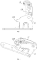
- FIG. 1 and FIG. 2 show a hinge assembly structure in the prior art.
- the hinge assembly includes a hinge plate 11 and an adapter 12 rotatably connected to the hinge plate 11.
- the hinge plate 11 is fixed on a cabinet of the refrigerator, and a door body of the refrigerator is fixed on the adapter 12, thereby achieving the rotatably connection of the cabinet and the door body.
- a hook-shaped stop 120 is generally formed on the adapter 12, and a protrusion 110 corresponding to the stop 120 is formed on the hinge plate 11; referring to FIG. 2 , based on the above structure, after the door body of the refrigerator is closed, the hook of the stop 120 can catch the protrusion 110, thereby keeping the closed state of the door body.
- this technical means of keeping the door body closed has the following disadvantages:
- the stop 120 needs to be deformed during the door body closing process to catch the protrusion 110 of the hinge plate 11. If the size of the hook of the stop 120 is too small, after the door body is closed, loss fitting might occur between the stop 120 and the protrusion 110 and cause the door body not to be closed tightly; if the size of the hook of the stop 120 is too large, the stop 120 needs to be deformed greatly when the door body is closed so that the stop 120 wears seriously and even is directly broken during use of the refrigerator.
- the present invention aims to at least solve one of the technical problems existing in the prior art.
- the present invention provides a door closer whose specific design manner is as follows.
- a door closer comprises a hinge plate, a hinge shaft disposed on the hinge plate, and an adapter disposed rotatably around the hinge shaft.
- the door closer further comprises a cam disposed on the hinge shaft, a peripheral side of the cam retracts inward the cam to form a first recessed region, an elastic mechanism is provided in the adapter, and the elastic mechanism has an abutting end for elastically abutting against the periphery of the cam; during the turning of the adapter, the abutting end moves relative to the periphery of the cam, and when the adapter turns to the side of the first recessed region of the cam, the abutting end enters the first recessed region to lock a positional relationship between the adapter and the hinge plate.
- the adapter is a housing
- the housing comprises a top plate and a bottom plate which are arranged opposite to each other
- a receiving cavity for receiving the elastic mechanism is formed between the top plate and the bottom plate
- the top plate and bottom plate extend towards the hinge shaft to form a top plate extension and a bottom plate extension located above and below the cam, respectively
- both the top plate extension and the bottom plate extension are provided with a rotational hole enabling the adapter to turn about the hinge shaft.
- the elastic mechanism comprises a spring and an elastic force release portion
- the spring is compressed and disposed in the receiving cavity in a radial direction of the hinge shaft, and an end of the spring away from the hinge shaft is fixedly disposed relative to the housing;
- the elastic force release portion is located between the spring and the cam to apply the elastic force of the spring to the periphery of the cam, and the abutting end is formed at an end of the elastic force release portion adjacent to the hinge shaft.
- the elastic force release portion comprises a bracket and a roller
- the bracket is disposed abutting against the spring
- a bracket tail extending into the spring is formed on a side of the bracket adjacent to spring
- the roller is rotatably disposed at the end of the bracket away from the spring and constitutes the abutting end
- an axis of rotation of the roller is parallel to an axis of rotation of the adapter.
- top plate and the bottom plate are formed with elongated guide holes in a radial direction of the hinge shaft, and both ends of the roller respectively have guide fitting portions which extend into the guide holes to limit the movement of the roller in the radial direction of the hinge shaft.
- an upper bushing and a lower bushing sleeved around the hinge shaft are disposed on an upper side and a lower side of the cam, respectively, and the top plate extension and the bottom plate extension are fitted outside the upper bushing and the lower bushing through the rotational holes, respectively.
- a second recessed region is formed on a side of the periphery of the cam opposite to the first recessed region; when the adapter turns to the side of the second recessed region of the cam, the abutting end enters the second recessed region to lock a positional relationship between the adapter and the hinge plate.
- the surface of the periphery of the cam on which the abutting end moves is further formed with at least one third recessed region which is located between the first recessed region and the second recessed region; when the adapter turns to the third recessed region of the cam, the abutting end enters the third recessed region to lock a positional relationship between the adapter and the hinge plate.
- the hinge shaft comprises a first shaft body and a second shaft body
- the first shaft body is fixed on the hinge plate and a fitting hole is formed therein in a height direction
- the second shaft body is rod-shaped and its lower end is non-rotatably fitted in the fitting hole.
- an internal thread of the fitting hole is connected to a screw whose height is adjustable, and the lower end of the second shaft body abuts against a top of the screw.
- the present invention further provides a refrigerator which comprises a cabinet having an accommodating compartment and a door body for closing the accommodating compartment, the refrigerator further comprises the abovementioned door closer, the hinge plate of the door closer is fixed on the cabinet, and the door body is fixed on the adapter; when the door body is closed, the adapter turns to the side of the first recessed region of the cam to keep the door body in a closed state.
- An advantageous effect of the present invention is as follows: based on the door closer structure provided by the present invention, in the application scenario where the door body is closed, the door closer can ensure that the door body can be closed tightly without damaging component parts, and meet the user's requirements for long-term and reliable use.
- FIG. 3 through FIG. 13 they are some preferred embodiments of the present invention.
- the refrigerator according to the present invention includes a cabinet (not shown) having an accommodating compartment, a door body 3 for closing the accommodating compartment, and a door closer 200 connecting the cabinet with the door body 3.
- the hinge plate 21 of the door closer 200 is fixed on the cabinet, and the door body 3 is fixed on an adapter 23.
- the underside of the door body 3 is recessed upward to form a groove 30, and the adapter 23 is embedded and fixed in the groove 30 to realize the connection between the door body 3 and the door closer 200;
- the door closer 200 is fixed on the cabinet via a fixing portion 210 on the hinge plate 21.
- fixing holes are provided on the fixing portion 210, and screws pass through the through holes to fix the hinge plate 21 on the refrigerator.
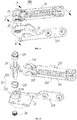
- the door closer 200 includes a hinge plate 21, a hinge shaft 22 provided on the hinge plate 21, and an adapter 23 rotatably disposed around the hinge shaft 22.
- the hinge shaft 22 includes a first shaft body 221 and a second shaft body 222.
- the first shaft body 221 is fixed on the hinge plate 21 and a fitting hole 2210 is formed therein in a height direction.
- the second shaft body 222 is rod-shaped and its lower end is non-rotatably fitted in the fitting hole 2210 of the second shaft body 222.
- the hinge shaft 22 may be integrally formed, or formed by splicing more shaft bodies, which will not be described in detail here.
- the door closer 200 further includes a cam 24 provided on the hinge shaft 22.
- a fitting hole 240 (not shown) is formed in the middle of the cam 24, and the second shaft body 222 passes through the fitting hole 240 fixes the cam 24.
- a peripheral side of the cam 24 retracts inward the cam 24 to form a first recessed region 241; an elastic mechanism is provided in the adapter 23, and the elastic mechanism has an abutting end for elastically abutting against the periphery of the cam 24;
- the abutting end of the elastic mechanism moves relative to the periphery of the cam 24, and when the adapter 23 turns to the side of the first recessed region 241 of the cam 24, the abutting end enters the first recessed region 241 to lock the positional relationship between the adapter 23 and the hinge plate 21.
- the first recessed region 241 gradually retracts inward the cam from the periphery of the cam 24 to form an indented arc surface.
- the abutting end of the elastic mechanism approaches the edge of the first recessed region 241, the abutting end can move inward the first recessed region 241 under the action of the elastic force of the elastic mechanism, thereby achieving the complete closing of the door body 3.
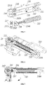
- this specific embodiment also has the following optimized settings: referring to FIG. 7 , when the door body 3 is completely closed, the abutment end of the elastic mechanism protrudes into the first recessed region 241.
- the first recessed region 241 has a recessed space continuing to extend inward the cam 24.
- the elastic mechanism can further provide the door body 3 with a force that drives it to continue to turn in the closing direction of the door body 3, thereby ensuring that the door body 3 is closed tightly.
- a side surface in contact with the abutting end during the opening process of the door body 3 is a circular arc surface.
- a spring 235 as an elastic force providing element of the elastic mechanism, does not have a compression or decompression process, so that the adapter 23 can smoothly turn about the hinge shaft 22, i.e., can ensure smoothness in the opening process of the door body 3.
- the adapter 23 is a housing, and the housing includes a top plate 231 and a bottom plate 232 which are arranged opposite to each other.
- a receiving cavity 230 for receiving the elastic mechanism is formed between the top plate 231 and the bottom plate 232.
- the top plate 231 and bottom plate 232 extend towards the hinge shaft 22 to form a top plate extension 2310 and a bottom plate extension 2320 located above and below the cam 24, respectively.
- Both the top plate extension 2310 and the bottom plate extension 2320 are provided with a rotational hole 234 enabling the adapter 23 to turn about the hinge shaft 22.
- the elastic mechanism includes a spring 235 and an elastic force release portion, the spring 235 is compressed and disposed in the receiving cavity 230 in a radial direction of the hinge shaft 222, and an end of the spring 235 away from the hinge shaft 222 is fixedly disposed relative to the housing.
- a baffle 233 is provided in the housing at an end far away from the top plate extension 2310 and the bottom plate extension 2320, and the end of the spring 235 away from the hinge shaft 222 abuts against and is fixed on a side of the baffle 233.
- the elastic force release portion in the present invention is located between the spring 235 and the cam 24 to apply the elastic force of the spring 235 to the periphery of the cam 24.
- the end of the elastic force release portion adjacent to the hinge shaft 222 constitutes the abutting end described above.
- the elastic force release portion includes a bracket 236 and a roller 237.
- the bracket 236 abuts against the spring 235
- a bracket tail 2360 extending into the spring 235 is formed on a side of the bracket 236 adjacent to spring 235, and the bracket tail 2360 can ensure that the bracket 236 does not disengage from the spring 235;
- the roller 237 is rotatably disposed at the end of the bracket 236 away from the spring 235.
- the roller 237 constitutes the abutting end described above.
- a rolling shaft 2371 allowing the roller 237 to rotate is formed in the roller 237, a pair of support sheets (not shown) are formed vertically opposite to each other on the side of the bracket 236 away from the spring 235, a receiving notch 2361 fitted with the rolling shaft 2371 is formed on each of the pair of support sheets, and the rolling shaft 2371 is fitted in the receiving notch 2361 to abut against the periphery of the cam 24 under the action of the elastic force of the spring 235.
- the axis of the rotation of the roller 237 is parallel to the axis of rotation of the adapter 23.
- the top plate 231 and the bottom plate 232 are formed with elongated guide holes 238 in a radial direction of the hinge shaft 22, and upper and lower ends of the rolling shaft 2371 of the roller 237 respectively extend into the guide holes 238 of the top plate 231 and the bottom plate 232; the upper and lower ends of the rolling shaft 2371 in the present embodiment form a guide fitting portion that limits the movement of the roller 237 in the radial direction of the hinge shaft 22.
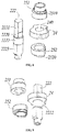
- an upper bushing 251 and a lower bushing 252 sleeved around the hinge shaft 22 are disposed on an upper side and a lower side of the cam 24, respectively.
- the top plate extension 2310 and the bottom plate extension 2320 are fitted outside the upper bushing 251 and the lower bushing 252 through the rotational holes 234, respectively.
- the upper bushing 251, the cam 24 and the lower bushing 252 are sleeved around the second shaft body 222 in turn from top to bottom.
- the cam 24 in the present invention is not rotatable with respect to the second shaft body 222.
- the fitting hole 240 in the middle of the cam 24 is set to be non-circular, and the second shaft body 222 is provided with a cam fitting portion 2220 that matches the fitting hole 240; an upper bushing fitting portion 2221 and a lower bushing fitting portion 2222 for fitting the upper bushing 251 and the lower bushing 252 are provided on an upper side and a lower side of the fitting portion 2220, respectively, wherein the lower bushing fitting portion 2222 has a projection (not shown) projecting from the surface of the fitting portion 2220, thereby avoiding downward movement of the cam 24 along the second shaft body 222.
- the upper bushing 251 and the lower bushing 252 are both disposed rotatable relative to the second shaft body 222, and the top plate extension 2310 and the bottom plate extension 2320 are fixedly disposed with respect to the upper bushing 251 and the lower bushing 252, respectively.
- the rotational hole 234 is provided as a non-circular profiled hole.
- the upper bushing 251 and the lower bushing 252 are respectively formed with an upper rotational hole mating portion 2510 and a lower rotational hole mating portion 2520 that mate with the rotational hole 234, thereby preventing the adapter 23 from rotating relative to the upper bushing 251 and the lower bushing 252.
- the upper bushing 251 and the lower bushing 252 are also set to be non-rotatable relative to the second shaft body 222, and the rotational holes 234 on the top plate extension 2310 and the bottom plate extension 2320 are set to be circular, thereby implementing rotatable arrangement of the adapter 23 relative to the hinge shaft 22.
- a second recessed region 242 is formed on a side of the periphery of the cam 24 opposite to the first recessed region 241.
- the abutting end namely, the roller 237 enters the second recessed region 242 to lock the positional relationship between the adapter 23 and the hinge plate 21.
- the roller 237 enters the second recessed region 242 to position the door body 3 at the certain opening angle, so that the door body 3 does not rotate freely when the user places items into or remove items from the refrigerator.
- the surface of the periphery of the cam 24 on which the roller 237 rolls is further formed with at least one third recessed region (not shown) which is located between the first recessed region and the second recessed region.
- the roller 237 enters the third recessed region to lock the positional relationship between the adapter 23 and the hinge plate 21; in a specific implementation process, as a preferred embodiment, the depth of the third recessed region is smaller than the depth of the first recessed region 241 and the second recessed region 242, so that after the door body 3 is stopped, the user may re-rotate the door body 3 with only a slight force.
- the fitting hole 2210 of the first shaft body 221 is a non-circular hole, and the lower end 2223 of the second shaft body 222 matches the non-circular hole, thereby avoiding the relative rotation of the first shaft body 221 and the second shaft body 222.
- the fitting hole 2210 is vertically through, an internal thread of the fitting hole 2210 is connected to a screw 26 whose height is adjustable, and the lower end of the second shaft body 222 abuts against the top of the screw 26. Based on this arrangement manner, if the door body 3 sags during the use of the refrigerator, the height position of the second screw 222 and the adapter 23 may be raised by rotating the screw 26 upward, thereby indirectly adjusting the height of the door body 3.
Landscapes
- Engineering & Computer Science (AREA)
- Mechanical Engineering (AREA)
- Chemical & Material Sciences (AREA)
- Combustion & Propulsion (AREA)
- Physics & Mathematics (AREA)
- Thermal Sciences (AREA)
- General Engineering & Computer Science (AREA)
- Refrigerator Housings (AREA)
- Hinges (AREA)
Applications Claiming Priority (2)
| Application Number | Priority Date | Filing Date | Title |
|---|---|---|---|
| CN201810374364.4A CN109695391A (zh) | 2018-04-24 | 2018-04-24 | 闭门器及具有该闭门器的冰箱 |
| PCT/CN2019/083724 WO2019206093A1 (fr) | 2018-04-24 | 2019-04-22 | Ferme-porte et réfrigérateur le comprenant |
Publications (2)
| Publication Number | Publication Date |
|---|---|
| EP3786400A1 true EP3786400A1 (fr) | 2021-03-03 |
| EP3786400A4 EP3786400A4 (fr) | 2021-05-19 |
Family
ID=66229987
Family Applications (1)
| Application Number | Title | Priority Date | Filing Date |
|---|---|---|---|
| EP19791803.0A Withdrawn EP3786400A4 (fr) | 2018-04-24 | 2019-04-22 | Ferme-porte et réfrigérateur le comprenant |
Country Status (5)
| Country | Link |
|---|---|
| EP (1) | EP3786400A4 (fr) |
| CN (1) | CN109695391A (fr) |
| AU (1) | AU2019258466A1 (fr) |
| MX (1) | MX2020011113A (fr) |
| WO (1) | WO2019206093A1 (fr) |
Families Citing this family (12)
| Publication number | Priority date | Publication date | Assignee | Title |
|---|---|---|---|---|
| US10995977B2 (en) * | 2019-08-28 | 2021-05-04 | Whirlpool Corporation | Mullion hinge assembly |
| CN114876299B (zh) * | 2019-08-28 | 2023-11-14 | 青岛海尔电冰箱有限公司 | 铰链组件及具有其的制冷设备 |
| US11913271B2 (en) * | 2020-05-20 | 2024-02-27 | Kason Industries, Inc. | Pivot hinge |
| CN111595092B (zh) * | 2020-05-27 | 2022-02-18 | 长虹美菱股份有限公司 | 一种冰箱铰链组件及基于其的冰箱 |
| US11982041B2 (en) * | 2021-02-23 | 2024-05-14 | Whirlpool Corporation | Spring-loaded side swing hinge with feedback elimination |
| CN115405179B (zh) * | 2021-05-28 | 2024-06-11 | 青岛海尔特种电冰柜有限公司 | 开闭调节装置及冰箱 |
| CN115596307B (zh) * | 2021-07-07 | 2026-01-09 | 青岛海尔电冰箱有限公司 | 闭门装置及具有其的冰箱 |
| CN113338739B (zh) * | 2021-07-12 | 2023-10-13 | 江苏玖星精密科技集团有限公司 | 一种自由嵌入式冰箱铰链 |
| CN115839583B (zh) * | 2021-09-18 | 2026-04-28 | 海信冰箱有限公司 | 冰箱 |
| CN114061213B (zh) * | 2021-11-04 | 2024-02-06 | 安徽康佳同创电器有限公司 | 一种冰箱闭门器及冰箱 |
| CN116336716B (zh) * | 2021-12-17 | 2025-05-16 | 青岛海尔智能技术研发有限公司 | 冰箱 |
| CN115235167B (zh) * | 2022-03-24 | 2024-02-27 | 海信冰箱有限公司 | 冰箱 |
Family Cites Families (13)
| Publication number | Priority date | Publication date | Assignee | Title |
|---|---|---|---|---|
| US3452387A (en) * | 1967-10-09 | 1969-07-01 | Ajax Hardware Mfg Corp | Closing device for doors |
| BE778938A (fr) * | 1971-02-11 | 1972-05-30 | Julio Escalona Julian | Dispositif de fermeture pour porte |
| DE102004041358B4 (de) * | 2004-08-25 | 2006-07-13 | Dorma Gmbh + Co. Kg | Obentürschließer |
| CN201420457Y (zh) * | 2009-04-21 | 2010-03-10 | 合肥美菱股份有限公司 | 电冰箱门卡簧自锁限位装置及电冰箱 |
| US9095214B2 (en) * | 2012-11-29 | 2015-08-04 | Mansfield Engineered Components, Inc. | Door closure mechanism for refrigerator or other appliance |
| KR102073004B1 (ko) * | 2013-04-12 | 2020-02-04 | 삼성전자주식회사 | 냉장고 |
| JP6449906B2 (ja) * | 2014-04-16 | 2019-01-09 | オーエル.エムアイ エス.アール.エル. | 扉および扉板などの回転動作のためのヒンジ |
| US20160083993A1 (en) * | 2014-09-22 | 2016-03-24 | Kason Industries, Inc. | Hinge and method of assembling same |
| CN104499860B (zh) * | 2014-11-19 | 2016-12-07 | 海达门控有限公司 | 一种开关门力可调式多段定位地弹簧 |
| CN104989208B (zh) * | 2015-08-07 | 2016-11-30 | 佛山市奥达金属制品有限公司 | 机械式开门延时地弹簧 |
| CN106223759A (zh) * | 2016-09-13 | 2016-12-14 | 佛山市奥达金属制品有限公司 | 多点定位凸轮 |
| CN106839619B (zh) * | 2017-01-04 | 2019-03-12 | 合肥华凌股份有限公司 | 冰箱的门体组件及冰箱 |
| CN107217937B (zh) * | 2017-06-26 | 2019-12-06 | 青岛海尔股份有限公司 | 铰链组件及具有该铰链组件的冰箱 |
-
2018
- 2018-04-24 CN CN201810374364.4A patent/CN109695391A/zh active Pending
-
2019
- 2019-04-22 WO PCT/CN2019/083724 patent/WO2019206093A1/fr not_active Ceased
- 2019-04-22 AU AU2019258466A patent/AU2019258466A1/en not_active Abandoned
- 2019-04-22 MX MX2020011113A patent/MX2020011113A/es unknown
- 2019-04-22 EP EP19791803.0A patent/EP3786400A4/fr not_active Withdrawn
Also Published As
| Publication number | Publication date |
|---|---|
| CN109695391A (zh) | 2019-04-30 |
| MX2020011113A (es) | 2020-11-11 |
| EP3786400A4 (fr) | 2021-05-19 |
| WO2019206093A1 (fr) | 2019-10-31 |
| AU2019258466A1 (en) | 2020-11-12 |
Similar Documents
| Publication | Publication Date | Title |
|---|---|---|
| EP3786400A1 (fr) | Ferme-porte et réfrigérateur le comprenant | |
| US8382216B2 (en) | Electric household appliance | |
| KR101543649B1 (ko) | 조절가능한 토크 힌지 | |
| US7934290B2 (en) | Door hinge device with fulcrum at variable position | |
| CN104727679B (zh) | 门铰链机构及洗碗机 | |
| WO2017109648A1 (fr) | Appareil de réfrigération | |
| CA2853774A1 (fr) | Appareil electromenager de cuisson pourvu d'une porte de four pivotante laterale dotee d'un verrou a capture automatique integre | |
| KR101138288B1 (ko) | 회동식 창호용 스테이바 | |
| US8677566B2 (en) | Hinge for doors or wings | |
| EP3786401A1 (fr) | Charnière invisible à arbre rotatif à configuration en forme de v | |
| KR102000902B1 (ko) | 경첩 장치 | |
| CN107130870A (zh) | 一种合页 | |
| KR100479006B1 (ko) | 김치냉장고용 힌지장치 | |
| CN115142752B (zh) | 一种多功能铰链 | |
| GB2134593A (en) | Door closing devices | |
| KR101544144B1 (ko) | 힌지장치 | |
| CN211081433U (zh) | 二段力缓冲铰链和柜体组件 | |
| CN204002217U (zh) | 门铰链机构及洗碗机 | |
| WO2023151221A1 (fr) | Dispositif d'ouverture et de fermeture de porte et appareil de matériel | |
| CN209817684U (zh) | 平开窗的把手组件 | |
| KR101146047B1 (ko) | 도어 회동 어시스트 기구 | |
| CN111480986B (zh) | 一种鞋柜 | |
| CN222731344U (zh) | 柜体铰链 | |
| CN222526083U (zh) | 一种冰箱门体缓冲结构及冰箱 | |
| CN219910466U (zh) | 一种防夹门框及门扇 |
Legal Events
| Date | Code | Title | Description |
|---|---|---|---|
| STAA | Information on the status of an ep patent application or granted ep patent |
Free format text: STATUS: THE INTERNATIONAL PUBLICATION HAS BEEN MADE |
|
| PUAI | Public reference made under article 153(3) epc to a published international application that has entered the european phase |
Free format text: ORIGINAL CODE: 0009012 |
|
| STAA | Information on the status of an ep patent application or granted ep patent |
Free format text: STATUS: REQUEST FOR EXAMINATION WAS MADE |
|
| 17P | Request for examination filed |
Effective date: 20200325 |
|
| AK | Designated contracting states |
Kind code of ref document: A1 Designated state(s): AL AT BE BG CH CY CZ DE DK EE ES FI FR GB GR HR HU IE IS IT LI LT LU LV MC MK MT NL NO PL PT RO RS SE SI SK SM TR |
|
| AX | Request for extension of the european patent |
Extension state: BA ME |
|
| A4 | Supplementary search report drawn up and despatched |
Effective date: 20210421 |
|
| RIC1 | Information provided on ipc code assigned before grant |
Ipc: E05D 3/02 20060101AFI20210415BHEP Ipc: E05D 11/10 20060101ALI20210415BHEP Ipc: E05D 7/00 20060101ALI20210415BHEP Ipc: E05F 1/10 20060101ALI20210415BHEP Ipc: E05F 1/12 20060101ALI20210415BHEP Ipc: F25D 23/02 20060101ALI20210415BHEP |
|
| DAV | Request for validation of the european patent (deleted) | ||
| DAX | Request for extension of the european patent (deleted) | ||
| STAA | Information on the status of an ep patent application or granted ep patent |
Free format text: STATUS: THE APPLICATION IS DEEMED TO BE WITHDRAWN |
|
| 18D | Application deemed to be withdrawn |
Effective date: 20211123 |