EP3786424B1 - Moteur à combustion interne à allumage externe à formation intérieure de mélange destiné à la combustion d'un mélange de carburant gazeux et d'air - Google Patents
Moteur à combustion interne à allumage externe à formation intérieure de mélange destiné à la combustion d'un mélange de carburant gazeux et d'air Download PDFInfo
- Publication number
- EP3786424B1 EP3786424B1 EP20192339.8A EP20192339A EP3786424B1 EP 3786424 B1 EP3786424 B1 EP 3786424B1 EP 20192339 A EP20192339 A EP 20192339A EP 3786424 B1 EP3786424 B1 EP 3786424B1
- Authority
- EP
- European Patent Office
- Prior art keywords
- combustion chamber
- combustion engine
- internal combustion
- spark
- ignition
- Prior art date
- Legal status (The legal status is an assumption and is not a legal conclusion. Google has not performed a legal analysis and makes no representation as to the accuracy of the status listed.)
- Active
Links
Images
Classifications
-
- F—MECHANICAL ENGINEERING; LIGHTING; HEATING; WEAPONS; BLASTING
- F02—COMBUSTION ENGINES; HOT-GAS OR COMBUSTION-PRODUCT ENGINE PLANTS
- F02B—INTERNAL-COMBUSTION PISTON ENGINES; COMBUSTION ENGINES IN GENERAL
- F02B23/00—Other engines characterised by special shape or construction of combustion chambers to improve operation
- F02B23/08—Other engines characterised by special shape or construction of combustion chambers to improve operation with positive ignition
-
- F—MECHANICAL ENGINEERING; LIGHTING; HEATING; WEAPONS; BLASTING
- F02—COMBUSTION ENGINES; HOT-GAS OR COMBUSTION-PRODUCT ENGINE PLANTS
- F02B—INTERNAL-COMBUSTION PISTON ENGINES; COMBUSTION ENGINES IN GENERAL
- F02B23/00—Other engines characterised by special shape or construction of combustion chambers to improve operation
- F02B23/08—Other engines characterised by special shape or construction of combustion chambers to improve operation with positive ignition
- F02B23/10—Other engines characterised by special shape or construction of combustion chambers to improve operation with positive ignition with separate admission of air and fuel into cylinder
-
- F—MECHANICAL ENGINEERING; LIGHTING; HEATING; WEAPONS; BLASTING
- F02—COMBUSTION ENGINES; HOT-GAS OR COMBUSTION-PRODUCT ENGINE PLANTS
- F02F—CYLINDERS, PISTONS OR CASINGS, FOR COMBUSTION ENGINES; ARRANGEMENTS OF SEALINGS IN COMBUSTION ENGINES
- F02F1/00—Cylinders; Cylinder heads
- F02F1/24—Cylinder heads
- F02F1/242—Arrangement of spark plugs or injectors
-
- F—MECHANICAL ENGINEERING; LIGHTING; HEATING; WEAPONS; BLASTING
- F02—COMBUSTION ENGINES; HOT-GAS OR COMBUSTION-PRODUCT ENGINE PLANTS
- F02M—SUPPLYING COMBUSTION ENGINES IN GENERAL WITH COMBUSTIBLE MIXTURES OR CONSTITUENTS THEREOF
- F02M21/00—Apparatus for supplying engines with non-liquid fuels, e.g. gaseous fuels stored in liquid form
- F02M21/02—Apparatus for supplying engines with non-liquid fuels, e.g. gaseous fuels stored in liquid form for gaseous fuels
- F02M21/0203—Apparatus for supplying engines with non-liquid fuels, e.g. gaseous fuels stored in liquid form for gaseous fuels characterised by the type of gaseous fuel
- F02M21/0206—Non-hydrocarbon fuels, e.g. hydrogen, ammonia or carbon monoxide
-
- F—MECHANICAL ENGINEERING; LIGHTING; HEATING; WEAPONS; BLASTING
- F02—COMBUSTION ENGINES; HOT-GAS OR COMBUSTION-PRODUCT ENGINE PLANTS
- F02M—SUPPLYING COMBUSTION ENGINES IN GENERAL WITH COMBUSTIBLE MIXTURES OR CONSTITUENTS THEREOF
- F02M21/00—Apparatus for supplying engines with non-liquid fuels, e.g. gaseous fuels stored in liquid form
- F02M21/02—Apparatus for supplying engines with non-liquid fuels, e.g. gaseous fuels stored in liquid form for gaseous fuels
- F02M21/0218—Details on the gaseous fuel supply system, e.g. tanks, valves, pipes, pumps, rails, injectors or mixers
- F02M21/0248—Injectors
-
- F—MECHANICAL ENGINEERING; LIGHTING; HEATING; WEAPONS; BLASTING
- F02—COMBUSTION ENGINES; HOT-GAS OR COMBUSTION-PRODUCT ENGINE PLANTS
- F02M—SUPPLYING COMBUSTION ENGINES IN GENERAL WITH COMBUSTIBLE MIXTURES OR CONSTITUENTS THEREOF
- F02M21/00—Apparatus for supplying engines with non-liquid fuels, e.g. gaseous fuels stored in liquid form
- F02M21/02—Apparatus for supplying engines with non-liquid fuels, e.g. gaseous fuels stored in liquid form for gaseous fuels
- F02M21/0218—Details on the gaseous fuel supply system, e.g. tanks, valves, pipes, pumps, rails, injectors or mixers
- F02M21/0248—Injectors
- F02M21/0275—Injectors for in-cylinder direct injection, e.g. injector combined with spark plug
-
- F—MECHANICAL ENGINEERING; LIGHTING; HEATING; WEAPONS; BLASTING
- F02—COMBUSTION ENGINES; HOT-GAS OR COMBUSTION-PRODUCT ENGINE PLANTS
- F02M—SUPPLYING COMBUSTION ENGINES IN GENERAL WITH COMBUSTIBLE MIXTURES OR CONSTITUENTS THEREOF
- F02M21/00—Apparatus for supplying engines with non-liquid fuels, e.g. gaseous fuels stored in liquid form
- F02M21/02—Apparatus for supplying engines with non-liquid fuels, e.g. gaseous fuels stored in liquid form for gaseous fuels
- F02M21/0218—Details on the gaseous fuel supply system, e.g. tanks, valves, pipes, pumps, rails, injectors or mixers
- F02M21/0248—Injectors
- F02M21/0281—Adapters, sockets or the like to mount injection valves onto engines; Fuel guiding passages between injectors and the air intake system or the combustion chamber
-
- F—MECHANICAL ENGINEERING; LIGHTING; HEATING; WEAPONS; BLASTING
- F02—COMBUSTION ENGINES; HOT-GAS OR COMBUSTION-PRODUCT ENGINE PLANTS
- F02B—INTERNAL-COMBUSTION PISTON ENGINES; COMBUSTION ENGINES IN GENERAL
- F02B1/00—Engines characterised by fuel-air mixture compression
- F02B1/02—Engines characterised by fuel-air mixture compression with positive ignition
- F02B1/08—Engines characterised by fuel-air mixture compression with positive ignition with separate admission of air and fuel into cylinder
-
- Y—GENERAL TAGGING OF NEW TECHNOLOGICAL DEVELOPMENTS; GENERAL TAGGING OF CROSS-SECTIONAL TECHNOLOGIES SPANNING OVER SEVERAL SECTIONS OF THE IPC; TECHNICAL SUBJECTS COVERED BY FORMER USPC CROSS-REFERENCE ART COLLECTIONS [XRACs] AND DIGESTS
- Y02—TECHNOLOGIES OR APPLICATIONS FOR MITIGATION OR ADAPTATION AGAINST CLIMATE CHANGE
- Y02T—CLIMATE CHANGE MITIGATION TECHNOLOGIES RELATED TO TRANSPORTATION
- Y02T10/00—Road transport of goods or passengers
- Y02T10/10—Internal combustion engine [ICE] based vehicles
- Y02T10/12—Improving ICE efficiencies
-
- Y—GENERAL TAGGING OF NEW TECHNOLOGICAL DEVELOPMENTS; GENERAL TAGGING OF CROSS-SECTIONAL TECHNOLOGIES SPANNING OVER SEVERAL SECTIONS OF THE IPC; TECHNICAL SUBJECTS COVERED BY FORMER USPC CROSS-REFERENCE ART COLLECTIONS [XRACs] AND DIGESTS
- Y02—TECHNOLOGIES OR APPLICATIONS FOR MITIGATION OR ADAPTATION AGAINST CLIMATE CHANGE
- Y02T—CLIMATE CHANGE MITIGATION TECHNOLOGIES RELATED TO TRANSPORTATION
- Y02T10/00—Road transport of goods or passengers
- Y02T10/10—Internal combustion engine [ICE] based vehicles
- Y02T10/30—Use of alternative fuels, e.g. biofuels
Definitions
- the invention relates to a spark-ignited internal combustion engine with internal mixture formation for the combustion of a mixture of a gaseous fuel and air while performing work.
- the gaseous fuel can preferably be hydrogen.
- the invention further relates to a motor vehicle, preferably a commercial vehicle, with such an internal combustion engine and the use of such a spark-ignited internal combustion engine as a generator drive motor for power generation or for maritime applications.
- Hydrogen can become very important as a fuel due to its chemical properties and can be used particularly advantageously in combustion engines to generate torque.
- Hydrogen combustion engines are already known from the state of the art. These are combustion engines that run on hydrogen as fuel. The basis is the oxyhydrogen reaction (two parts hydrogen with one part oxygen) in a rotating piston cylinder. The basic concept of such combustion engines therefore corresponds to that of conventional reciprocating piston engines with one or more cylinders.
- the documents are only an example. EP 1 647 684 A2 and DE 103 59 445 A1 referred to.
- Another example is from the DE 10 2009 037160 A1 known.
- modified Otto engines are usually used as spark-ignition internal combustion engines, although hydrogen combustion engines that work according to the diesel process are also known.
- hydrogen combustion engines that work as spark-ignition internal combustion engines the hydrogen is introduced into the combustion chamber using a nozzle and ignited with a spark plug. This creates a flame front that spreads from the spark plug towards the cylinder wall.
- hydrogen combustion engines are known that operate with external mixture formation (manifold injection) as well as hydrogen combustion engines that operate with internal mixture formation (direct injection).
- the hydrogen stored under pressure is blown into the intake pipe in front of the inlet valves in gaseous form at a slight excess pressure.
- gaseous hydrogen is blown under pressure directly into the combustion chamber.
- the charge mixture is heated significantly during the compression phase and then ignited with a spark plug.
- natural gas and biogas engines as well as the use of other fuel gases are also known.
- combustion speed of hydrogen is in the range of 200 m/s and, under the same ambient conditions, is significantly higher than the combustion speed of diesel and gasoline (approx. 20 m/s).
- combustion anomalies such as knocking, pre-ignition or backfiring can also occur in hydrogen engines.
- Combustion anomalies tend to occur at "hot spots", i.e. particularly hot spots in the combustion chamber.
- Critical combustion chamber areas are in particular the spark plug or the area around the spark plug, the exhaust valve plate, valve webs and the combustion chamber roof.
- a disadvantage of the hydrogen combustion engines known from the state of the art is that the components in the combustion chamber, in particular the spark plug and the injection valve, are exposed to high thermal stress, which has a detrimental effect on their function and service life.
- the WO 2015/138987 A1 an injection-ignition device with a pre-chamber, wherein the pre-chamber is in fluid communication with a combustion chamber of an internal combustion engine.
- This can be designed as an integrated, screwed, single unit that is suitable for operating high-performance direct injection engines with spark ignition with gaseous fuels in diluted or lean conditions.
- the WO 2015/138987 A1 also methods for combustion processes for operating a spark-ignition engine with direct injection and lean combustion, wherein injection events are to occur during the intake and compression strokes in an engine.
- the US 3 572 297 A an internal combustion engine that operates by direct injection of hydrogen into its cylinders. Hydrogen is mixed with part of the air in the cylinders to form a combustible mixture that is ignited and burned simultaneously with the injection over part of the expansion stroke and in some cases over part of the compression stroke.
- Double-disk valves are used, which open and close depending on the detected engine operating parameters.
- a valve ignition prechamber for an internal combustion engine which has a combustion chamber in which a main charge more or less diluted with a neutral gas is ignited.
- the prechamber has a stratification cavity into which ignition means open and into which a stratification injector can inject an easily ignitable pilot charge under pressure.
- a stratification valve can completely or partially close the stratification channel, in particular under the effect of the gas pressure prevailing in the combustion chamber.
- the object of the invention is in particular to provide such an internal combustion engine which reduces the thermal load on components in the combustion chamber.
- a spark-ignition internal combustion engine with internal mixture formation for combustion of a mixture of a gaseous Fuel and air are provided under work performance.
- the spark-ignition internal combustion engine (hereinafter also referred to as internal combustion engine or combustion motor) comprises at least one cylinder in which a combustion chamber is defined between a longitudinally movable piston and a cylinder head.
- the internal combustion engine further comprises, in a manner known per se, charge exchange valves for supplying air (air inlet valves) into the combustion chamber and charge exchange valves for removing exhaust gas (exhaust valves) from the combustion chamber.
- Each of the at least one cylinder includes an injection valve arranged in the cylinder head and a spark plug arranged in the cylinder head.
- the injection valve is used to feed the gaseous fuel into the combustion chamber, where the gaseous fuel mixes with air.
- the injection valve is arranged at a distance from the combustion chamber in a supply channel that opens directly into the combustion chamber.
- This supply channel is also referred to below as the first supply channel to better distinguish it from a further supply channel described below, which is referred to as the second supply channel.
- the injection valve does not protrude into the combustion chamber or directly border on it, but is arranged set back from it in the cylinder head. Gaseous fuel escaping through the injection valve in the direction of the combustion chamber therefore does not enter the combustion chamber directly, but must at least travel a distance in the supply channel before the gaseous fuel can enter the combustion chamber.
- the injection valve (or injection valve) is also called a direct injection valve because the gaseous fuel is injected under pressure directly into the combustion chamber via the supply channel or channels (internal mixture formation) and not, as with external mixture formation, in gaseous form with a slight overpressure into the intake pipe in front of the intake valves.
- the internal combustion engine further comprises a spark plug arranged in the cylinder head and having an ignition tip, which is arranged in a further feed channel opening into the combustion chamber, hereinafter referred to as the second feed channel, wherein the ignition tip is arranged at a distance from the opening of the second feed channel into the combustion chamber.
- the spark plug and its ignition tip do not protrude into the combustion chamber, but are arranged set back in the cylinder head.
- spark plug neither the spark plug nor the injection valve protrude directly into the actual combustion chamber of the piston, but are set back in the cylinder head.
- inventive arrangement of the spark plug and direct injection valve offers the particular advantage that these components are subjected to less thermal stress due to the setback. Accordingly, the spark plug has a longer service life and the direct injection valve can be constructed more cost-effectively.
- the direct injection valve does not extend into the combustion chamber, there are also more degrees of freedom for the direct injection valve in terms of design in order to optimize performance, and there is also no need to extensively redesign the cylinder head when using hydrogen from a liquid fuel.
- Another particular advantage is that the recessed arrangement of the gas injection valve and spark plug tip makes it possible - as described in more detail below - to burn lean mixtures cleanly. The reason for this is that during the intake process, a richer mixture (lower lambda) can be generated in the area of the second feed channel than in the combustion chamber, which can be ignited by the spark plug. This generates an ignition jet through the second feed channel to the combustion chamber, which means that even lean mixtures with a high lambda can be burned as completely and cleanly as possible. This in turn enables low nitrogen oxide emissions.
- the gaseous fuel is hydrogen.
- the injection valve can be in fluid communication with a hydrogen storage device.
- the gaseous fuel can also be another gaseous fuel.
- the first supply channel opens directly into the combustion chamber, and therefore does not open indirectly into the combustion chamber via the second supply channel.
- the two supply channels open into the combustion chamber at different points.
- the second supply channel is used to supply gaseous fuel and air to the ignition tip, which is set back from the combustion chamber.
- the second supply channel can open into the combustion chamber in a central region of a combustion chamber roof. It is particularly advantageous if the second supply channel opens into the combustion chamber in the middle of the combustion chamber roof.
- the cylinder head forms the combustion chamber roof, in particular the region of the cylinder head facing the piston.
- the combustion chamber the area that is limited between the longitudinally movable piston and the cylinder head is referred to here as the combustion chamber.
- the second supply channel and the first supply channel are not considered to be part of the combustion chamber, even if the combustion is ignited or initiated in the second supply channel, similar to a spark plug with a pre-chamber.
- the combustion chamber roof refers to the cylinder head wall that delimits the cylinder and through which the charge exchange (supply of air and fuel, expulsion of exhaust gases) takes place.
- the spark-ignition internal combustion engine comprises an engine control device which is designed to carry out a gas injection of the gaseous fuel by means of the injection valve during an intake process and to terminate it before the start of the compression phase.
- the gas injection of the gaseous fuel can take place during the intake process of the internal combustion engine, with the intake valves open and the piston moving downwards, ie away from the cylinder head.
- the engine control device can control the gas injection valve so that it closes before the compression phase in the cylinder begins.
- the spark-ignition internal combustion engine can be provided without a throttle valve.
- the efficiency of the internal combustion engine can be improved. In the case of exhaust gas recirculation and knowledge of the exhaust gas mass, this can also be taken into account as a control variable.
- the internal combustion engine can further comprise an exhaust gas recirculation system based on the donor cylinder principle, which is designed to recirculate exhaust gas from a subset of the cylinders of the internal combustion engine to an intake side.
- an exhaust gas recirculation system based on the donor cylinder principle, which is designed to recirculate exhaust gas from a subset of the cylinders of the internal combustion engine to an intake side.
- the internal combustion engine can, for example, have at least one exhaust gas turbocharger, which comprises a compressor and a turbine, as well as a charge air line for supplying compressed air to the internal combustion engine.
- the at least one cylinder of the internal combustion engine comprises a first cylinder group and a second cylinder group, the second Cylinder group works according to the donor cylinder principle.
- An exhaust manifold is provided which has a first section for collecting exhaust gas from the first cylinder group and a second section for collecting exhaust gas from the second cylinder group.
- a first exhaust line is provided which connects the first section of the exhaust manifold to the turbine, with a return line for exhaust gas recirculation from the second section of the exhaust manifold into the charge air line.
- the piston of the spark-ignition internal combustion engine can have a concave recess.
- a convex elevation can be provided in the concave recess.
- the first feed channel can have a constant cross-section, wherein preferably the length of the first feed channel is greater than its cross-sectional width.
- the second feed channel can have a constant cross-section, wherein preferably the length of the second feed channel is greater than its cross-sectional width.
- the first feed channel and/or the second feed channel can be produced by a bore or a core casting.
- the invention further relates to a motor vehicle with a spark-ignition internal combustion engine as described in this document.
- the motor vehicle can be a commercial vehicle, such as a truck or bus.
- the spark-ignited internal combustion engine 1 works according to the principle of internal mixture formation to burn a mixture of a gaseous fuel, here hydrogen, and air while performing work.
- the internal combustion engine 1 thus represents a hydrogen engine.
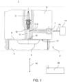
- the internal combustion engine 1 comprises at least one cylinder 2 in which a combustion chamber 3 between a longitudinally movable piston 4 and a cylinder head 6.
- the direction of movement of the piston 4 is shown schematically by the arrow 16.
- the piston 6 has a concave recess 5.
- FIG. 1 shows a schematic detailed view in section of just one cylinder head area of a cylinder 2 of the internal combustion engine 1.
- each of the cylinders 2 comprises a spark plug 9 arranged in the cylinder head 6, having an ignition tip 10, which is arranged in the second supply channel 11 opening into the combustion chamber.
- the opening of the second supply channel 11 into the combustion chamber 3 is identified by the reference number 12.
- the ignition tip 10 is arranged at a distance from the opening 12 of the second supply channel 11 into the combustion chamber 3.
- each of the cylinders 2 comprises an injection valve 7 arranged in the cylinder head 6, which can be designed as a control valve.
- the injection valve 7 is arranged at a distance from the combustion chamber 3 in a first supply channel 8.
- the first supply channel 8 opens indirectly into the combustion chamber 3 via the second supply channel 11.
- the injection valve 7 is in fluid connection with a hydrogen storage device 14 via a line 15.
- the first feed channel 8 opens into the second feed channel 11 between the ignition tip 10 and the opening 12 of the second feed channel 11 in the combustion chamber 3.
- the opening of the first feed channel 8 into the second feed channel 11 is identified by the reference number 13.
- the opening 12 of the second feed channel 11 into the combustion chamber 3 is located in the middle of the combustion chamber roof 17.
- the arrangement of the spark plug 9 and direct injection valve 7 according to the invention offers the particular advantage that these components are subjected to less thermal stress due to the setback. Accordingly, the spark plug 9 achieves a longer service life and the direct injection valve 7 can be constructed more cost-effectively.
- the internal combustion engine 3 further comprises charge exchange valves on each cylinder 2 for supplying air (air inlet valves) into the combustion chamber 3 and charge exchange valves for Discharge of exhaust gas (exhaust valves) from the combustion chamber 3, which are not shown in each case and can be designed in a manner known per se.
- the gas injection valve 7 is in signal connection with an engine control device 20 and is controlled by it.
- the engine control device 20 can be the engine control unit.
- the engine control device 20 is designed to carry out a gas injection of the gaseous fuel by means of the injection valve during an intake process and preferably to end it before the start of the compression phase. To this end, the engine control device 20 controls the gas injection valve 20 accordingly in order to open or close it.
- the mixture at the spark plug tip 10 is "richer", which increases the ignition readiness.
- the combustion directly at the spark plug initiates, similar to a spark plug with a pre-chamber, a propagation of the combustion with high energy in the main combustion chamber 3 via the feed channel 11, much greater than the ignition energy of a spark plug, and ensures that even lean mixtures in the combustion chamber 3 with a high lambda burn through completely.
- the arrangement of the spark plug 9 and the injection valve 7 set back from the combustion chamber 3 thus leads to a hydrogen enrichment in the second supply channel 11 and, upon ignition, to a type of "ignition jet" that propagates into the combustion chamber 3 via the feed channel 11. Because a reduced lambda always prevails at the spark plug 9 in the design shown, even very lean mixtures in the combustion chamber 3 are still reliably and completely burned via the "ignition jet”. This principle also makes it possible to dispense with the throttle valve, as already mentioned above.
- the engine control unit also regulates the "driver's request” in a known manner, i.e. torque and/or speed.
- the "amount of fuel to be injected” depends on the "accelerator pedal position", but takes into account the amount of combustion air (lambda).
- the air mass and, in the case of exhaust gas recirculation, the exhaust gas mass are also measured.
- the nitrogen oxide emissions can also be influenced. Basically, the higher the lambda, the lower the nitrogen oxide emissions.
- the internal combustion engine 1 can also have an exhaust gas recirculation system based on the donor cylinder principle, which is designed to recirculate exhaust gas from a subset of the cylinders 2 of the internal combustion engine 1 to an intake side.
- an exhaust gas recirculation system based on the donor cylinder principle, which is designed to recirculate exhaust gas from a subset of the cylinders 2 of the internal combustion engine 1 to an intake side.
- the entire exhaust gas from a cylinder is led directly back to the intake side. This achieves a stable exhaust gas recirculation rate (100/6).
- the exhaust gas turbocharger then only receives the exhaust gas mass from 5 cylinders.
- the exhaust gas recirculation line can usually also be switched off with a shut-off valve.
- the recirculated exhaust gas can also be cooled.
- a cylinder head for a diesel engine with a common rail injector and so-called side feed connection can be manufactured from a blank for the cylinder head, as well as the cylinder head 6 for the hydrogen engine or the internal combustion engine 1 according to Figure 1 .
- Such an internal combustion engine 1 or such a hydrogen engine is not only suitable for motor vehicles (trucks and buses), but is also suitable as a generator drive motor for power generation or for maritime applications. If the hydrogen is regenerative
- the internal combustion engine 1 can be described as a CO2 -neutral internal combustion engine and can make a significant contribution to low-emission electricity generation, particularly during periods of low light.
Landscapes
- Engineering & Computer Science (AREA)
- Chemical & Material Sciences (AREA)
- Combustion & Propulsion (AREA)
- Mechanical Engineering (AREA)
- General Engineering & Computer Science (AREA)
- Chemical Kinetics & Catalysis (AREA)
- General Chemical & Material Sciences (AREA)
- Oil, Petroleum & Natural Gas (AREA)
- Combustion Methods Of Internal-Combustion Engines (AREA)
- Output Control And Ontrol Of Special Type Engine (AREA)
Claims (10)
- Moteur à combustion interne à allumage commandé (1) avec formation de mélange interne pour la combustion d'un mélange d'un carburant gazeux et d'air en fonctionnement, ledit moteur comprenant
au moins un cylindre (2) dans lequel une chambre de combustion (3) est délimitée entre un piston (4) mobile longitudinalement et une culasse (6), chacun des au moins un cylindre (2) comprenant :une soupape d'injection directe (7) qui est disposée dans la culasse (6) et qui est disposée à distance de la chambre de combustion (3) dans un premier conduit d'alimentation (8) qui débouche directement dans la chambre de combustion (3) ; etune bougie d'allumage (9) qui est disposée dans la culasse (6), qui comporte une pointe d'allumage (10) et qui est disposée dans un deuxième conduit d'alimentation (11) qui débouche dans la chambre de combustion, la pointe d'allumage (10) étant disposée à distance de l'embouchure (12) du deuxième conduit d'alimentation (11) dans la chambre de combustion (3) ;un dispositif de commande de moteur (20) qui est conçu pour effectuer une injection du carburant gazeux au moyen de la soupape d'injection directe (7) pendant un processus d'admission et pour y mettre fin avant le début de la phase de compression ;caractérisé en ce que le premier conduit d'alimentation (8) débouche dans la chambre de combustion (3) en un point différent du deuxième conduit d'alimentation (11). - Moteur à combustion interne à allumage commandé (1) selon la revendication 1,a) le carburant gazeux étant de l'hydrogène ; et/oub) la soupape d'injection directe (7) étant en communication fluidique avec un dispositif de stockage d'hydrogène (14).
- Moteur à combustion interne à allumage commandé (1) selon l'une des revendications précédentes,
le deuxième conduit d'alimentation (11) débouchant dans la chambre de combustion (3) dans une zone médiane d'un toit de chambre de combustion (17), et débouchant de préférence dans la chambre de combustion (3) au milieu du toit de chambre de combustion (17). - Moteur à combustion interne à allumage commandé (1) selon l'une des revendications précédentes,
le moteur à combustion interne ne comportant pas de papillon de gaz. - Moteur à combustion interne à allumage commandé selon l'une des revendications précédentes,
ledit moteur comprenant une recirculation de gaz d'échappement selon le principe du cylindre donneur, laquelle est conçue pour renvoyer les gaz d'échappement d'un sous-ensemble de cylindres du moteur à combustion interne vers un côté admission. - Moteur à combustion interne à allumage commandé (1) selon l'une des revendications précédentes,
le piston comportant une cavité concave (5). - Moteur à combustion interne à allumage commandé selon la revendication 6,
une élévation convexe étant prévue dans la cavité concave. - Véhicule automobile, de préférence véhicule utilitaire, tel qu'un camion ou un bus, équipé d'un moteur à combustion interne à allumage commandé selon l'une des revendications précédentes.
- Utilisation d'un moteur à combustion interne à allumage commandé (1) selon l'une des revendications 1 à 7 comme moteur d'entraînement de générateur dans la production de l'électricité ou dans des applications maritimes.
- Utilisation d'un moteur à combustion interne à allumage commandé (1) selon l'une des revendications 1 à 7,
le carburant gazeux étant injecté sous pression directement dans la chambre de combustion (3) par le biais du premier conduit d'alimentation (8).
Applications Claiming Priority (1)
| Application Number | Priority Date | Filing Date | Title |
|---|---|---|---|
| DE102019006019.9A DE102019006019A1 (de) | 2019-08-26 | 2019-08-26 | Fremdgezündete Brennkraftmaschine mit innerer Gemischbildung zur Verbrennung eines Gemischs aus einem gasförmigen Kraftstoff und Luft |
Publications (2)
| Publication Number | Publication Date |
|---|---|
| EP3786424A1 EP3786424A1 (fr) | 2021-03-03 |
| EP3786424B1 true EP3786424B1 (fr) | 2025-02-19 |
Family
ID=72234676
Family Applications (1)
| Application Number | Title | Priority Date | Filing Date |
|---|---|---|---|
| EP20192339.8A Active EP3786424B1 (fr) | 2019-08-26 | 2020-08-24 | Moteur à combustion interne à allumage externe à formation intérieure de mélange destiné à la combustion d'un mélange de carburant gazeux et d'air |
Country Status (2)
| Country | Link |
|---|---|
| EP (1) | EP3786424B1 (fr) |
| DE (1) | DE102019006019A1 (fr) |
Families Citing this family (3)
| Publication number | Priority date | Publication date | Assignee | Title |
|---|---|---|---|---|
| CN113719343B (zh) * | 2021-07-29 | 2022-12-23 | 东风商用车有限公司 | 分体侧置式射流点火系统 |
| CN113719375B (zh) * | 2021-07-29 | 2023-01-24 | 东风商用车有限公司 | 侧置式射流点火系统燃料供给结构 |
| DE102023116067A1 (de) * | 2023-06-20 | 2024-12-24 | Alstom Holdings | Fahrzeug und entsprechendes Verfahren |
Citations (1)
| Publication number | Priority date | Publication date | Assignee | Title |
|---|---|---|---|---|
| DE102009037160A1 (de) * | 2009-08-03 | 2011-06-22 | Er-System | Verfahren zum Betreiben eines Gasmotors, sowie Gasmotor |
Family Cites Families (7)
| Publication number | Priority date | Publication date | Assignee | Title |
|---|---|---|---|---|
| US3572297A (en) * | 1970-01-26 | 1971-03-23 | Schoeppel Roger J | Hydrogen fueled internal combustion engine |
| DE19622945A1 (de) * | 1996-06-07 | 1997-12-11 | Wtz Fuer Motoren Und Maschinen | Verfahren zum Betrieb von Brennkraftmaschinen |
| DE10359445A1 (de) * | 2003-12-17 | 2005-07-28 | Enginion Ag | Wasserstoff-Verbrennungsmotor |
| DE102004049589A1 (de) * | 2004-10-12 | 2006-04-20 | Bayerische Motoren Werke Ag | Wasserstoffmotor mit optimierter Kraftstoffeinblasvorrichtung |
| US9200560B2 (en) * | 2013-01-11 | 2015-12-01 | Caterpillar Inc. | Gaseous common rail fuel system and high compression ratio engine using same |
| WO2015138987A1 (fr) * | 2014-03-14 | 2015-09-17 | Advanced Green Technologies, Llc | Injecteur-allumeur à préchambre pour combustion de carburant gazeux, et systèmes et méthodes associés |
| FR3061743B1 (fr) * | 2017-01-12 | 2019-08-16 | Vianney Rabhi | Prechambre d'allumage a clapet |
-
2019
- 2019-08-26 DE DE102019006019.9A patent/DE102019006019A1/de active Pending
-
2020
- 2020-08-24 EP EP20192339.8A patent/EP3786424B1/fr active Active
Patent Citations (1)
| Publication number | Priority date | Publication date | Assignee | Title |
|---|---|---|---|---|
| DE102009037160A1 (de) * | 2009-08-03 | 2011-06-22 | Er-System | Verfahren zum Betreiben eines Gasmotors, sowie Gasmotor |
Also Published As
| Publication number | Publication date |
|---|---|
| EP3786424A1 (fr) | 2021-03-03 |
| DE102019006019A1 (de) | 2021-03-04 |
Similar Documents
| Publication | Publication Date | Title |
|---|---|---|
| DE10147529B4 (de) | Verfahren zum Betreiben einer mit selbstzündbarem Kraftstoff betriebenen Brennkraftmaschine | |
| WO2019068484A1 (fr) | Moteur à combustion interne pour véhicule automobile | |
| EP3786424B1 (fr) | Moteur à combustion interne à allumage externe à formation intérieure de mélange destiné à la combustion d'un mélange de carburant gazeux et d'air | |
| DE102017120512B4 (de) | Verfahren zum Betreiben eines Wasserstoffmotors für ein Kraftfahrzeug | |
| DE102011056519A1 (de) | Diesel-Benzin-Hybridmotor | |
| DE102018109939A1 (de) | Verbrennungsmotor | |
| DE102018000706A1 (de) | Verfahren zum Betreiben einer Verbrennungskraftmaschine für ein Kraftfahrzeug | |
| DE102016218707A1 (de) | Hubkolben-Brennkraftmaschine | |
| DE102008045915A1 (de) | Brennkraftmaschine mit Vorkammerzündung | |
| DE2851504A1 (de) | Verfahren zum betreiben einer brennkraftmaschine mit innerer verbrennung und variablem verdichtungsverhaeltnis, sowie brennkraftmaschine zum durchfuehren des verfahrens | |
| EP3953574B1 (fr) | Procédé pour faire fonctionner un moteur à combustion interne | |
| WO2004101972A1 (fr) | Procede de fonctionnement d'un moteur a combustion interne | |
| DE102012202080A1 (de) | Hubkolben-Brennkraftmaschine | |
| DE102017009613A1 (de) | Verfahren zum Betreiben einer Verbrennungskraftmaschine eines Kraftfahrzeugs, insbesondere eines Kraftwagens | |
| DE2602127A1 (de) | Mehrfach fremdgezuendeter verbrennungsmotor mit auspuffgasrueckfuehrung | |
| EP4028659B1 (fr) | Procédé de fonctionnement d'un moteur à combustion interne | |
| DE102009049755A1 (de) | Verfahren zum Betreiben einer Kolbenbrennkraftmaschine sowie Kolbenbrennkraftmaschine | |
| DE102015221325B4 (de) | Verfahren zum Betreiben einer Brennkraftmaschine und Brennkraftmaschine | |
| WO2021074173A1 (fr) | Procédé de fonctionnement d'un moteur à combustion interne | |
| DE102015223351A1 (de) | Verfahren zum Betreiben einer Brennkraftmaschine und Brennkraftmaschine | |
| DE102014019563A1 (de) | Verfahren zum Unterdrücken von irregulären Verbrennungen eines Ottomotors | |
| DE102016205875B4 (de) | Direkteinspritzende fremdgezündete Brennkraftmaschine mit im Zylinderrohr angeordneter Einspritzvorrichtung und Verfahren zum Betreiben einer derartigen Brennkraftmaschine | |
| DE102023203862B4 (de) | Verfahren zum Betreiben einer Hubkolben-Verbrennungskraftmaschine | |
| EP1007833B1 (fr) | Procede de realisation de l'allumage dans un moteur a gaz a pistons alternatifs multicylindre par injection d'un gaz d'allumage | |
| DE2307284B2 (de) | Viertakt-brennkraftmaschine mit fremdzuendung mit einem ueber einen durchlass verbundenem zylinderpaar |
Legal Events
| Date | Code | Title | Description |
|---|---|---|---|
| PUAI | Public reference made under article 153(3) epc to a published international application that has entered the european phase |
Free format text: ORIGINAL CODE: 0009012 |
|
| STAA | Information on the status of an ep patent application or granted ep patent |
Free format text: STATUS: THE APPLICATION HAS BEEN PUBLISHED |
|
| AK | Designated contracting states |
Kind code of ref document: A1 Designated state(s): AL AT BE BG CH CY CZ DE DK EE ES FI FR GB GR HR HU IE IS IT LI LT LU LV MC MK MT NL NO PL PT RO RS SE SI SK SM TR |
|
| AX | Request for extension of the european patent |
Extension state: BA ME |
|
| STAA | Information on the status of an ep patent application or granted ep patent |
Free format text: STATUS: REQUEST FOR EXAMINATION WAS MADE |
|
| 17P | Request for examination filed |
Effective date: 20210831 |
|
| RBV | Designated contracting states (corrected) |
Designated state(s): AL AT BE BG CH CY CZ DE DK EE ES FI FR GB GR HR HU IE IS IT LI LT LU LV MC MK MT NL NO PL PT RO RS SE SI SK SM TR |
|
| STAA | Information on the status of an ep patent application or granted ep patent |
Free format text: STATUS: EXAMINATION IS IN PROGRESS |
|
| 17Q | First examination report despatched |
Effective date: 20220905 |
|
| GRAP | Despatch of communication of intention to grant a patent |
Free format text: ORIGINAL CODE: EPIDOSNIGR1 |
|
| STAA | Information on the status of an ep patent application or granted ep patent |
Free format text: STATUS: GRANT OF PATENT IS INTENDED |
|
| INTG | Intention to grant announced |
Effective date: 20240930 |
|
| GRAS | Grant fee paid |
Free format text: ORIGINAL CODE: EPIDOSNIGR3 |
|
| GRAA | (expected) grant |
Free format text: ORIGINAL CODE: 0009210 |
|
| STAA | Information on the status of an ep patent application or granted ep patent |
Free format text: STATUS: THE PATENT HAS BEEN GRANTED |
|
| AK | Designated contracting states |
Kind code of ref document: B1 Designated state(s): AL AT BE BG CH CY CZ DE DK EE ES FI FR GB GR HR HU IE IS IT LI LT LU LV MC MK MT NL NO PL PT RO RS SE SI SK SM TR |
|
| REG | Reference to a national code |
Ref country code: GB Ref legal event code: FG4D Free format text: NOT ENGLISH |
|
| REG | Reference to a national code |
Ref country code: CH Ref legal event code: EP |
|
| REG | Reference to a national code |
Ref country code: DE Ref legal event code: R096 Ref document number: 502020010413 Country of ref document: DE |
|
| REG | Reference to a national code |
Ref country code: IE Ref legal event code: FG4D Free format text: LANGUAGE OF EP DOCUMENT: GERMAN |
|
| REG | Reference to a national code |
Ref country code: NL Ref legal event code: FP |
|
| REG | Reference to a national code |
Ref country code: SE Ref legal event code: TRGR |
|
| PG25 | Lapsed in a contracting state [announced via postgrant information from national office to epo] |
Ref country code: RS Free format text: LAPSE BECAUSE OF FAILURE TO SUBMIT A TRANSLATION OF THE DESCRIPTION OR TO PAY THE FEE WITHIN THE PRESCRIBED TIME-LIMIT Effective date: 20250519 |
|
| PG25 | Lapsed in a contracting state [announced via postgrant information from national office to epo] |
Ref country code: FI Free format text: LAPSE BECAUSE OF FAILURE TO SUBMIT A TRANSLATION OF THE DESCRIPTION OR TO PAY THE FEE WITHIN THE PRESCRIBED TIME-LIMIT Effective date: 20250219 |
|
| PG25 | Lapsed in a contracting state [announced via postgrant information from national office to epo] |
Ref country code: PL Free format text: LAPSE BECAUSE OF FAILURE TO SUBMIT A TRANSLATION OF THE DESCRIPTION OR TO PAY THE FEE WITHIN THE PRESCRIBED TIME-LIMIT Effective date: 20250219 |
|
| PG25 | Lapsed in a contracting state [announced via postgrant information from national office to epo] |
Ref country code: ES Free format text: LAPSE BECAUSE OF FAILURE TO SUBMIT A TRANSLATION OF THE DESCRIPTION OR TO PAY THE FEE WITHIN THE PRESCRIBED TIME-LIMIT Effective date: 20250219 |
|
| REG | Reference to a national code |
Ref country code: LT Ref legal event code: MG9D |
|
| PG25 | Lapsed in a contracting state [announced via postgrant information from national office to epo] |
Ref country code: NO Free format text: LAPSE BECAUSE OF FAILURE TO SUBMIT A TRANSLATION OF THE DESCRIPTION OR TO PAY THE FEE WITHIN THE PRESCRIBED TIME-LIMIT Effective date: 20250519 Ref country code: IS Free format text: LAPSE BECAUSE OF FAILURE TO SUBMIT A TRANSLATION OF THE DESCRIPTION OR TO PAY THE FEE WITHIN THE PRESCRIBED TIME-LIMIT Effective date: 20250619 |
|
| PG25 | Lapsed in a contracting state [announced via postgrant information from national office to epo] |
Ref country code: HR Free format text: LAPSE BECAUSE OF FAILURE TO SUBMIT A TRANSLATION OF THE DESCRIPTION OR TO PAY THE FEE WITHIN THE PRESCRIBED TIME-LIMIT Effective date: 20250219 |
|
| PG25 | Lapsed in a contracting state [announced via postgrant information from national office to epo] |
Ref country code: LV Free format text: LAPSE BECAUSE OF FAILURE TO SUBMIT A TRANSLATION OF THE DESCRIPTION OR TO PAY THE FEE WITHIN THE PRESCRIBED TIME-LIMIT Effective date: 20250219 Ref country code: PT Free format text: LAPSE BECAUSE OF FAILURE TO SUBMIT A TRANSLATION OF THE DESCRIPTION OR TO PAY THE FEE WITHIN THE PRESCRIBED TIME-LIMIT Effective date: 20250620 |
|
| PG25 | Lapsed in a contracting state [announced via postgrant information from national office to epo] |
Ref country code: GR Free format text: LAPSE BECAUSE OF FAILURE TO SUBMIT A TRANSLATION OF THE DESCRIPTION OR TO PAY THE FEE WITHIN THE PRESCRIBED TIME-LIMIT Effective date: 20250520 Ref country code: BG Free format text: LAPSE BECAUSE OF FAILURE TO SUBMIT A TRANSLATION OF THE DESCRIPTION OR TO PAY THE FEE WITHIN THE PRESCRIBED TIME-LIMIT Effective date: 20250219 |
|
| PGFP | Annual fee paid to national office [announced via postgrant information from national office to epo] |
Ref country code: NL Payment date: 20250825 Year of fee payment: 6 |
|
| PG25 | Lapsed in a contracting state [announced via postgrant information from national office to epo] |
Ref country code: SM Free format text: LAPSE BECAUSE OF FAILURE TO SUBMIT A TRANSLATION OF THE DESCRIPTION OR TO PAY THE FEE WITHIN THE PRESCRIBED TIME-LIMIT Effective date: 20250219 |
|
| PG25 | Lapsed in a contracting state [announced via postgrant information from national office to epo] |
Ref country code: DK Free format text: LAPSE BECAUSE OF FAILURE TO SUBMIT A TRANSLATION OF THE DESCRIPTION OR TO PAY THE FEE WITHIN THE PRESCRIBED TIME-LIMIT Effective date: 20250219 |
|
| PGFP | Annual fee paid to national office [announced via postgrant information from national office to epo] |
Ref country code: DE Payment date: 20250827 Year of fee payment: 6 |
|
| PGFP | Annual fee paid to national office [announced via postgrant information from national office to epo] |
Ref country code: IT Payment date: 20250825 Year of fee payment: 6 |
|
| PGFP | Annual fee paid to national office [announced via postgrant information from national office to epo] |
Ref country code: GB Payment date: 20250826 Year of fee payment: 6 |
|
| PGFP | Annual fee paid to national office [announced via postgrant information from national office to epo] |
Ref country code: FR Payment date: 20250825 Year of fee payment: 6 |
|
| PGFP | Annual fee paid to national office [announced via postgrant information from national office to epo] |
Ref country code: SE Payment date: 20250825 Year of fee payment: 6 |
|
| PG25 | Lapsed in a contracting state [announced via postgrant information from national office to epo] |
Ref country code: CZ Free format text: LAPSE BECAUSE OF FAILURE TO SUBMIT A TRANSLATION OF THE DESCRIPTION OR TO PAY THE FEE WITHIN THE PRESCRIBED TIME-LIMIT Effective date: 20250219 Ref country code: EE Free format text: LAPSE BECAUSE OF FAILURE TO SUBMIT A TRANSLATION OF THE DESCRIPTION OR TO PAY THE FEE WITHIN THE PRESCRIBED TIME-LIMIT Effective date: 20250219 |
|
| PG25 | Lapsed in a contracting state [announced via postgrant information from national office to epo] |
Ref country code: RO Free format text: LAPSE BECAUSE OF FAILURE TO SUBMIT A TRANSLATION OF THE DESCRIPTION OR TO PAY THE FEE WITHIN THE PRESCRIBED TIME-LIMIT Effective date: 20250219 |
|
| PG25 | Lapsed in a contracting state [announced via postgrant information from national office to epo] |
Ref country code: SK Free format text: LAPSE BECAUSE OF FAILURE TO SUBMIT A TRANSLATION OF THE DESCRIPTION OR TO PAY THE FEE WITHIN THE PRESCRIBED TIME-LIMIT Effective date: 20250219 |
|
| REG | Reference to a national code |
Ref country code: DE Ref legal event code: R097 Ref document number: 502020010413 Country of ref document: DE |
|
| PLBE | No opposition filed within time limit |
Free format text: ORIGINAL CODE: 0009261 |
|
| STAA | Information on the status of an ep patent application or granted ep patent |
Free format text: STATUS: NO OPPOSITION FILED WITHIN TIME LIMIT |
|
| REG | Reference to a national code |
Ref country code: CH Ref legal event code: L10 Free format text: ST27 STATUS EVENT CODE: U-0-0-L10-L00 (AS PROVIDED BY THE NATIONAL OFFICE) Effective date: 20251231 |
|
| 26N | No opposition filed |
Effective date: 20251120 |
|
| REG | Reference to a national code |
Ref country code: CH Ref legal event code: H13 Free format text: ST27 STATUS EVENT CODE: U-0-0-H10-H13 (AS PROVIDED BY THE NATIONAL OFFICE) Effective date: 20260324 |
|
| PG25 | Lapsed in a contracting state [announced via postgrant information from national office to epo] |
Ref country code: MC Free format text: LAPSE BECAUSE OF FAILURE TO SUBMIT A TRANSLATION OF THE DESCRIPTION OR TO PAY THE FEE WITHIN THE PRESCRIBED TIME-LIMIT Effective date: 20250219 |
|
| PG25 | Lapsed in a contracting state [announced via postgrant information from national office to epo] |
Ref country code: LU Free format text: LAPSE BECAUSE OF NON-PAYMENT OF DUE FEES Effective date: 20250824 |
|
| PG25 | Lapsed in a contracting state [announced via postgrant information from national office to epo] |
Ref country code: CH Free format text: LAPSE BECAUSE OF NON-PAYMENT OF DUE FEES Effective date: 20250831 |