EP3786514B1 - Station zur gravimetrischen verteilung von kondensiertem gas in flüssigem zustand, und verfahren zum betrieb einer solchen station - Google Patents
Station zur gravimetrischen verteilung von kondensiertem gas in flüssigem zustand, und verfahren zum betrieb einer solchen station Download PDFInfo
- Publication number
- EP3786514B1 EP3786514B1 EP20191763.0A EP20191763A EP3786514B1 EP 3786514 B1 EP3786514 B1 EP 3786514B1 EP 20191763 A EP20191763 A EP 20191763A EP 3786514 B1 EP3786514 B1 EP 3786514B1
- Authority
- EP
- European Patent Office
- Prior art keywords
- tank
- pressure
- stationary
- station
- circuit
- Prior art date
- Legal status (The legal status is an assumption and is not a legal conclusion. Google has not performed a legal analysis and makes no representation as to the accuracy of the status listed.)
- Active
Links
Images

Classifications
-
- F—MECHANICAL ENGINEERING; LIGHTING; HEATING; WEAPONS; BLASTING
- F17—STORING OR DISTRIBUTING GASES OR LIQUIDS
- F17C—VESSELS FOR CONTAINING OR STORING COMPRESSED, LIQUEFIED OR SOLIDIFIED GASES; FIXED-CAPACITY GAS-HOLDERS; FILLING VESSELS WITH, OR DISCHARGING FROM VESSELS, COMPRESSED, LIQUEFIED, OR SOLIDIFIED GASES
- F17C5/00—Methods or apparatus for filling containers with liquefied, solidified, or compressed gases under pressures
-
- F—MECHANICAL ENGINEERING; LIGHTING; HEATING; WEAPONS; BLASTING
- F17—STORING OR DISTRIBUTING GASES OR LIQUIDS
- F17C—VESSELS FOR CONTAINING OR STORING COMPRESSED, LIQUEFIED OR SOLIDIFIED GASES; FIXED-CAPACITY GAS-HOLDERS; FILLING VESSELS WITH, OR DISCHARGING FROM VESSELS, COMPRESSED, LIQUEFIED, OR SOLIDIFIED GASES
- F17C2201/00—Vessel construction, in particular geometry, arrangement or size
- F17C2201/05—Size
- F17C2201/054—Size medium (>1 m3)
-
- F—MECHANICAL ENGINEERING; LIGHTING; HEATING; WEAPONS; BLASTING
- F17—STORING OR DISTRIBUTING GASES OR LIQUIDS
- F17C—VESSELS FOR CONTAINING OR STORING COMPRESSED, LIQUEFIED OR SOLIDIFIED GASES; FIXED-CAPACITY GAS-HOLDERS; FILLING VESSELS WITH, OR DISCHARGING FROM VESSELS, COMPRESSED, LIQUEFIED, OR SOLIDIFIED GASES
- F17C2205/00—Vessel construction, in particular mounting arrangements, attachments or identifications means
- F17C2205/03—Fluid connections, filters, valves, closure means or other attachments
- F17C2205/0302—Fittings, valves, filters, or components in connection with the gas storage device
- F17C2205/0323—Valves
- F17C2205/0326—Valves electrically actuated
-
- F—MECHANICAL ENGINEERING; LIGHTING; HEATING; WEAPONS; BLASTING
- F17—STORING OR DISTRIBUTING GASES OR LIQUIDS
- F17C—VESSELS FOR CONTAINING OR STORING COMPRESSED, LIQUEFIED OR SOLIDIFIED GASES; FIXED-CAPACITY GAS-HOLDERS; FILLING VESSELS WITH, OR DISCHARGING FROM VESSELS, COMPRESSED, LIQUEFIED, OR SOLIDIFIED GASES
- F17C2205/00—Vessel construction, in particular mounting arrangements, attachments or identifications means
- F17C2205/03—Fluid connections, filters, valves, closure means or other attachments
- F17C2205/0302—Fittings, valves, filters, or components in connection with the gas storage device
- F17C2205/0323—Valves
- F17C2205/0332—Safety valves or pressure relief valves
-
- F—MECHANICAL ENGINEERING; LIGHTING; HEATING; WEAPONS; BLASTING
- F17—STORING OR DISTRIBUTING GASES OR LIQUIDS
- F17C—VESSELS FOR CONTAINING OR STORING COMPRESSED, LIQUEFIED OR SOLIDIFIED GASES; FIXED-CAPACITY GAS-HOLDERS; FILLING VESSELS WITH, OR DISCHARGING FROM VESSELS, COMPRESSED, LIQUEFIED, OR SOLIDIFIED GASES
- F17C2205/00—Vessel construction, in particular mounting arrangements, attachments or identifications means
- F17C2205/03—Fluid connections, filters, valves, closure means or other attachments
- F17C2205/0302—Fittings, valves, filters, or components in connection with the gas storage device
- F17C2205/0352—Pipes
- F17C2205/0367—Arrangements in parallel
-
- F—MECHANICAL ENGINEERING; LIGHTING; HEATING; WEAPONS; BLASTING
- F17—STORING OR DISTRIBUTING GASES OR LIQUIDS
- F17C—VESSELS FOR CONTAINING OR STORING COMPRESSED, LIQUEFIED OR SOLIDIFIED GASES; FIXED-CAPACITY GAS-HOLDERS; FILLING VESSELS WITH, OR DISCHARGING FROM VESSELS, COMPRESSED, LIQUEFIED, OR SOLIDIFIED GASES
- F17C2205/00—Vessel construction, in particular mounting arrangements, attachments or identifications means
- F17C2205/03—Fluid connections, filters, valves, closure means or other attachments
- F17C2205/0302—Fittings, valves, filters, or components in connection with the gas storage device
- F17C2205/0376—Dispensing pistols
-
- F—MECHANICAL ENGINEERING; LIGHTING; HEATING; WEAPONS; BLASTING
- F17—STORING OR DISTRIBUTING GASES OR LIQUIDS
- F17C—VESSELS FOR CONTAINING OR STORING COMPRESSED, LIQUEFIED OR SOLIDIFIED GASES; FIXED-CAPACITY GAS-HOLDERS; FILLING VESSELS WITH, OR DISCHARGING FROM VESSELS, COMPRESSED, LIQUEFIED, OR SOLIDIFIED GASES
- F17C2221/00—Handled fluid, in particular type of fluid
- F17C2221/01—Pure fluids
- F17C2221/014—Nitrogen
-
- F—MECHANICAL ENGINEERING; LIGHTING; HEATING; WEAPONS; BLASTING
- F17—STORING OR DISTRIBUTING GASES OR LIQUIDS
- F17C—VESSELS FOR CONTAINING OR STORING COMPRESSED, LIQUEFIED OR SOLIDIFIED GASES; FIXED-CAPACITY GAS-HOLDERS; FILLING VESSELS WITH, OR DISCHARGING FROM VESSELS, COMPRESSED, LIQUEFIED, OR SOLIDIFIED GASES
- F17C2221/00—Handled fluid, in particular type of fluid
- F17C2221/03—Mixtures
- F17C2221/031—Air
-
- F—MECHANICAL ENGINEERING; LIGHTING; HEATING; WEAPONS; BLASTING
- F17—STORING OR DISTRIBUTING GASES OR LIQUIDS
- F17C—VESSELS FOR CONTAINING OR STORING COMPRESSED, LIQUEFIED OR SOLIDIFIED GASES; FIXED-CAPACITY GAS-HOLDERS; FILLING VESSELS WITH, OR DISCHARGING FROM VESSELS, COMPRESSED, LIQUEFIED, OR SOLIDIFIED GASES
- F17C2221/00—Handled fluid, in particular type of fluid
- F17C2221/03—Mixtures
- F17C2221/032—Hydrocarbons
- F17C2221/033—Methane, e.g. natural gas, CNG, LNG, GNL, GNC, PLNG
-
- F—MECHANICAL ENGINEERING; LIGHTING; HEATING; WEAPONS; BLASTING
- F17—STORING OR DISTRIBUTING GASES OR LIQUIDS
- F17C—VESSELS FOR CONTAINING OR STORING COMPRESSED, LIQUEFIED OR SOLIDIFIED GASES; FIXED-CAPACITY GAS-HOLDERS; FILLING VESSELS WITH, OR DISCHARGING FROM VESSELS, COMPRESSED, LIQUEFIED, OR SOLIDIFIED GASES
- F17C2223/00—Handled fluid before transfer, i.e. state of fluid when stored in the vessel or before transfer from the vessel
- F17C2223/01—Handled fluid before transfer, i.e. state of fluid when stored in the vessel or before transfer from the vessel characterised by the phase
- F17C2223/0146—Two-phase
- F17C2223/0153—Liquefied gas, e.g. LPG, GPL
- F17C2223/0161—Liquefied gas, e.g. LPG, GPL cryogenic, e.g. LNG, GNL, PLNG
-
- F—MECHANICAL ENGINEERING; LIGHTING; HEATING; WEAPONS; BLASTING
- F17—STORING OR DISTRIBUTING GASES OR LIQUIDS
- F17C—VESSELS FOR CONTAINING OR STORING COMPRESSED, LIQUEFIED OR SOLIDIFIED GASES; FIXED-CAPACITY GAS-HOLDERS; FILLING VESSELS WITH, OR DISCHARGING FROM VESSELS, COMPRESSED, LIQUEFIED, OR SOLIDIFIED GASES
- F17C2223/00—Handled fluid before transfer, i.e. state of fluid when stored in the vessel or before transfer from the vessel
- F17C2223/03—Handled fluid before transfer, i.e. state of fluid when stored in the vessel or before transfer from the vessel characterised by the pressure level
- F17C2223/033—Small pressure, e.g. for liquefied gas
-
- F—MECHANICAL ENGINEERING; LIGHTING; HEATING; WEAPONS; BLASTING
- F17—STORING OR DISTRIBUTING GASES OR LIQUIDS
- F17C—VESSELS FOR CONTAINING OR STORING COMPRESSED, LIQUEFIED OR SOLIDIFIED GASES; FIXED-CAPACITY GAS-HOLDERS; FILLING VESSELS WITH, OR DISCHARGING FROM VESSELS, COMPRESSED, LIQUEFIED, OR SOLIDIFIED GASES
- F17C2225/00—Handled fluid after transfer, i.e. state of fluid after transfer from the vessel
- F17C2225/01—Handled fluid after transfer, i.e. state of fluid after transfer from the vessel characterised by the phase
- F17C2225/0146—Two-phase
- F17C2225/0153—Liquefied gas, e.g. LPG, GPL
- F17C2225/0161—Liquefied gas, e.g. LPG, GPL cryogenic, e.g. LNG, GNL, PLNG
-
- F—MECHANICAL ENGINEERING; LIGHTING; HEATING; WEAPONS; BLASTING
- F17—STORING OR DISTRIBUTING GASES OR LIQUIDS
- F17C—VESSELS FOR CONTAINING OR STORING COMPRESSED, LIQUEFIED OR SOLIDIFIED GASES; FIXED-CAPACITY GAS-HOLDERS; FILLING VESSELS WITH, OR DISCHARGING FROM VESSELS, COMPRESSED, LIQUEFIED, OR SOLIDIFIED GASES
- F17C2225/00—Handled fluid after transfer, i.e. state of fluid after transfer from the vessel
- F17C2225/03—Handled fluid after transfer, i.e. state of fluid after transfer from the vessel characterised by the pressure level
- F17C2225/033—Small pressure, e.g. for liquefied gas
-
- F—MECHANICAL ENGINEERING; LIGHTING; HEATING; WEAPONS; BLASTING
- F17—STORING OR DISTRIBUTING GASES OR LIQUIDS
- F17C—VESSELS FOR CONTAINING OR STORING COMPRESSED, LIQUEFIED OR SOLIDIFIED GASES; FIXED-CAPACITY GAS-HOLDERS; FILLING VESSELS WITH, OR DISCHARGING FROM VESSELS, COMPRESSED, LIQUEFIED, OR SOLIDIFIED GASES
- F17C2227/00—Transfer of fluids, i.e. method or means for transferring the fluid; Heat exchange with the fluid
- F17C2227/01—Propulsion of the fluid
- F17C2227/0107—Propulsion of the fluid by pressurising the ullage
-
- F—MECHANICAL ENGINEERING; LIGHTING; HEATING; WEAPONS; BLASTING
- F17—STORING OR DISTRIBUTING GASES OR LIQUIDS
- F17C—VESSELS FOR CONTAINING OR STORING COMPRESSED, LIQUEFIED OR SOLIDIFIED GASES; FIXED-CAPACITY GAS-HOLDERS; FILLING VESSELS WITH, OR DISCHARGING FROM VESSELS, COMPRESSED, LIQUEFIED, OR SOLIDIFIED GASES
- F17C2227/00—Transfer of fluids, i.e. method or means for transferring the fluid; Heat exchange with the fluid
- F17C2227/01—Propulsion of the fluid
- F17C2227/0121—Propulsion of the fluid by gravity
-
- F—MECHANICAL ENGINEERING; LIGHTING; HEATING; WEAPONS; BLASTING
- F17—STORING OR DISTRIBUTING GASES OR LIQUIDS
- F17C—VESSELS FOR CONTAINING OR STORING COMPRESSED, LIQUEFIED OR SOLIDIFIED GASES; FIXED-CAPACITY GAS-HOLDERS; FILLING VESSELS WITH, OR DISCHARGING FROM VESSELS, COMPRESSED, LIQUEFIED, OR SOLIDIFIED GASES
- F17C2227/00—Transfer of fluids, i.e. method or means for transferring the fluid; Heat exchange with the fluid
- F17C2227/03—Heat exchange with the fluid
- F17C2227/0302—Heat exchange with the fluid by heating
- F17C2227/0309—Heat exchange with the fluid by heating using another fluid
- F17C2227/0311—Air heating
-
- F—MECHANICAL ENGINEERING; LIGHTING; HEATING; WEAPONS; BLASTING
- F17—STORING OR DISTRIBUTING GASES OR LIQUIDS
- F17C—VESSELS FOR CONTAINING OR STORING COMPRESSED, LIQUEFIED OR SOLIDIFIED GASES; FIXED-CAPACITY GAS-HOLDERS; FILLING VESSELS WITH, OR DISCHARGING FROM VESSELS, COMPRESSED, LIQUEFIED, OR SOLIDIFIED GASES
- F17C2227/00—Transfer of fluids, i.e. method or means for transferring the fluid; Heat exchange with the fluid
- F17C2227/03—Heat exchange with the fluid
- F17C2227/0367—Localisation of heat exchange
- F17C2227/0388—Localisation of heat exchange separate
-
- F—MECHANICAL ENGINEERING; LIGHTING; HEATING; WEAPONS; BLASTING
- F17—STORING OR DISTRIBUTING GASES OR LIQUIDS
- F17C—VESSELS FOR CONTAINING OR STORING COMPRESSED, LIQUEFIED OR SOLIDIFIED GASES; FIXED-CAPACITY GAS-HOLDERS; FILLING VESSELS WITH, OR DISCHARGING FROM VESSELS, COMPRESSED, LIQUEFIED, OR SOLIDIFIED GASES
- F17C2227/00—Transfer of fluids, i.e. method or means for transferring the fluid; Heat exchange with the fluid
- F17C2227/04—Methods for emptying or filling
- F17C2227/047—Methods for emptying or filling by repeating a process cycle
-
- F—MECHANICAL ENGINEERING; LIGHTING; HEATING; WEAPONS; BLASTING
- F17—STORING OR DISTRIBUTING GASES OR LIQUIDS
- F17C—VESSELS FOR CONTAINING OR STORING COMPRESSED, LIQUEFIED OR SOLIDIFIED GASES; FIXED-CAPACITY GAS-HOLDERS; FILLING VESSELS WITH, OR DISCHARGING FROM VESSELS, COMPRESSED, LIQUEFIED, OR SOLIDIFIED GASES
- F17C2250/00—Accessories; Control means; Indicating, measuring or monitoring of parameters
- F17C2250/03—Control means
- F17C2250/032—Control means using computers
-
- F—MECHANICAL ENGINEERING; LIGHTING; HEATING; WEAPONS; BLASTING
- F17—STORING OR DISTRIBUTING GASES OR LIQUIDS
- F17C—VESSELS FOR CONTAINING OR STORING COMPRESSED, LIQUEFIED OR SOLIDIFIED GASES; FIXED-CAPACITY GAS-HOLDERS; FILLING VESSELS WITH, OR DISCHARGING FROM VESSELS, COMPRESSED, LIQUEFIED, OR SOLIDIFIED GASES
- F17C2250/00—Accessories; Control means; Indicating, measuring or monitoring of parameters
- F17C2250/04—Indicating or measuring of parameters as input values
- F17C2250/0404—Parameters indicated or measured
- F17C2250/043—Pressure
-
- F—MECHANICAL ENGINEERING; LIGHTING; HEATING; WEAPONS; BLASTING
- F17—STORING OR DISTRIBUTING GASES OR LIQUIDS
- F17C—VESSELS FOR CONTAINING OR STORING COMPRESSED, LIQUEFIED OR SOLIDIFIED GASES; FIXED-CAPACITY GAS-HOLDERS; FILLING VESSELS WITH, OR DISCHARGING FROM VESSELS, COMPRESSED, LIQUEFIED, OR SOLIDIFIED GASES
- F17C2250/00—Accessories; Control means; Indicating, measuring or monitoring of parameters
- F17C2250/04—Indicating or measuring of parameters as input values
- F17C2250/0404—Parameters indicated or measured
- F17C2250/0439—Temperature
-
- F—MECHANICAL ENGINEERING; LIGHTING; HEATING; WEAPONS; BLASTING
- F17—STORING OR DISTRIBUTING GASES OR LIQUIDS
- F17C—VESSELS FOR CONTAINING OR STORING COMPRESSED, LIQUEFIED OR SOLIDIFIED GASES; FIXED-CAPACITY GAS-HOLDERS; FILLING VESSELS WITH, OR DISCHARGING FROM VESSELS, COMPRESSED, LIQUEFIED, OR SOLIDIFIED GASES
- F17C2250/00—Accessories; Control means; Indicating, measuring or monitoring of parameters
- F17C2250/04—Indicating or measuring of parameters as input values
- F17C2250/0404—Parameters indicated or measured
- F17C2250/0443—Flow or movement of content
-
- F—MECHANICAL ENGINEERING; LIGHTING; HEATING; WEAPONS; BLASTING
- F17—STORING OR DISTRIBUTING GASES OR LIQUIDS
- F17C—VESSELS FOR CONTAINING OR STORING COMPRESSED, LIQUEFIED OR SOLIDIFIED GASES; FIXED-CAPACITY GAS-HOLDERS; FILLING VESSELS WITH, OR DISCHARGING FROM VESSELS, COMPRESSED, LIQUEFIED, OR SOLIDIFIED GASES
- F17C2250/00—Accessories; Control means; Indicating, measuring or monitoring of parameters
- F17C2250/04—Indicating or measuring of parameters as input values
- F17C2250/0404—Parameters indicated or measured
- F17C2250/0447—Composition; Humidity
- F17C2250/0452—Concentration of a product
-
- F—MECHANICAL ENGINEERING; LIGHTING; HEATING; WEAPONS; BLASTING
- F17—STORING OR DISTRIBUTING GASES OR LIQUIDS
- F17C—VESSELS FOR CONTAINING OR STORING COMPRESSED, LIQUEFIED OR SOLIDIFIED GASES; FIXED-CAPACITY GAS-HOLDERS; FILLING VESSELS WITH, OR DISCHARGING FROM VESSELS, COMPRESSED, LIQUEFIED, OR SOLIDIFIED GASES
- F17C2250/00—Accessories; Control means; Indicating, measuring or monitoring of parameters
- F17C2250/06—Controlling or regulating of parameters as output values
- F17C2250/0605—Parameters
- F17C2250/0626—Pressure
-
- F—MECHANICAL ENGINEERING; LIGHTING; HEATING; WEAPONS; BLASTING
- F17—STORING OR DISTRIBUTING GASES OR LIQUIDS
- F17C—VESSELS FOR CONTAINING OR STORING COMPRESSED, LIQUEFIED OR SOLIDIFIED GASES; FIXED-CAPACITY GAS-HOLDERS; FILLING VESSELS WITH, OR DISCHARGING FROM VESSELS, COMPRESSED, LIQUEFIED, OR SOLIDIFIED GASES
- F17C2250/00—Accessories; Control means; Indicating, measuring or monitoring of parameters
- F17C2250/07—Actions triggered by measured parameters
- F17C2250/072—Action when predefined value is reached
- F17C2250/075—Action when predefined value is reached when full
-
- F—MECHANICAL ENGINEERING; LIGHTING; HEATING; WEAPONS; BLASTING
- F17—STORING OR DISTRIBUTING GASES OR LIQUIDS
- F17C—VESSELS FOR CONTAINING OR STORING COMPRESSED, LIQUEFIED OR SOLIDIFIED GASES; FIXED-CAPACITY GAS-HOLDERS; FILLING VESSELS WITH, OR DISCHARGING FROM VESSELS, COMPRESSED, LIQUEFIED, OR SOLIDIFIED GASES
- F17C2260/00—Purposes of gas storage and gas handling
- F17C2260/02—Improving properties related to fluid or fluid transfer
- F17C2260/021—Avoiding over pressurising
-
- F—MECHANICAL ENGINEERING; LIGHTING; HEATING; WEAPONS; BLASTING
- F17—STORING OR DISTRIBUTING GASES OR LIQUIDS
- F17C—VESSELS FOR CONTAINING OR STORING COMPRESSED, LIQUEFIED OR SOLIDIFIED GASES; FIXED-CAPACITY GAS-HOLDERS; FILLING VESSELS WITH, OR DISCHARGING FROM VESSELS, COMPRESSED, LIQUEFIED, OR SOLIDIFIED GASES
- F17C2260/00—Purposes of gas storage and gas handling
- F17C2260/02—Improving properties related to fluid or fluid transfer
- F17C2260/026—Improving properties related to fluid or fluid transfer by calculation
-
- F—MECHANICAL ENGINEERING; LIGHTING; HEATING; WEAPONS; BLASTING
- F17—STORING OR DISTRIBUTING GASES OR LIQUIDS
- F17C—VESSELS FOR CONTAINING OR STORING COMPRESSED, LIQUEFIED OR SOLIDIFIED GASES; FIXED-CAPACITY GAS-HOLDERS; FILLING VESSELS WITH, OR DISCHARGING FROM VESSELS, COMPRESSED, LIQUEFIED, OR SOLIDIFIED GASES
- F17C2260/00—Purposes of gas storage and gas handling
- F17C2260/04—Reducing risks and environmental impact
- F17C2260/044—Avoiding pollution or contamination
-
- F—MECHANICAL ENGINEERING; LIGHTING; HEATING; WEAPONS; BLASTING
- F17—STORING OR DISTRIBUTING GASES OR LIQUIDS
- F17C—VESSELS FOR CONTAINING OR STORING COMPRESSED, LIQUEFIED OR SOLIDIFIED GASES; FIXED-CAPACITY GAS-HOLDERS; FILLING VESSELS WITH, OR DISCHARGING FROM VESSELS, COMPRESSED, LIQUEFIED, OR SOLIDIFIED GASES
- F17C2265/00—Effects achieved by gas storage or gas handling
- F17C2265/03—Treating the boil-off
- F17C2265/032—Treating the boil-off by recovery
- F17C2265/033—Treating the boil-off by recovery with cooling
- F17C2265/034—Treating the boil-off by recovery with cooling with condensing the gas phase
-
- F—MECHANICAL ENGINEERING; LIGHTING; HEATING; WEAPONS; BLASTING
- F17—STORING OR DISTRIBUTING GASES OR LIQUIDS
- F17C—VESSELS FOR CONTAINING OR STORING COMPRESSED, LIQUEFIED OR SOLIDIFIED GASES; FIXED-CAPACITY GAS-HOLDERS; FILLING VESSELS WITH, OR DISCHARGING FROM VESSELS, COMPRESSED, LIQUEFIED, OR SOLIDIFIED GASES
- F17C2265/00—Effects achieved by gas storage or gas handling
- F17C2265/06—Fluid distribution
- F17C2265/065—Fluid distribution for refuelling vehicle fuel tanks
-
- F—MECHANICAL ENGINEERING; LIGHTING; HEATING; WEAPONS; BLASTING
- F17—STORING OR DISTRIBUTING GASES OR LIQUIDS
- F17C—VESSELS FOR CONTAINING OR STORING COMPRESSED, LIQUEFIED OR SOLIDIFIED GASES; FIXED-CAPACITY GAS-HOLDERS; FILLING VESSELS WITH, OR DISCHARGING FROM VESSELS, COMPRESSED, LIQUEFIED, OR SOLIDIFIED GASES
- F17C2270/00—Applications
- F17C2270/01—Applications for fluid transport or storage
- F17C2270/0165—Applications for fluid transport or storage on the road
- F17C2270/0168—Applications for fluid transport or storage on the road by vehicles
Definitions
- the invention relates to the distribution of condensed gas in the liquid state (e.g. liquefied natural gas or LNG) from a stationary tank to a tank on board a vehicle, typically a vehicle running on natural gas.
- condensed gas in the liquid state e.g. liquefied natural gas or LNG
- Natural gas essentially composed of methane (chemical formula CH4), is an abundant resource. Used as fuel in internal combustion engines, natural gas has the advantage of being little polluting compared to hydrocarbons (gasoline, fuel oil) from petroleum refining.
- This double advantage allows it to hold a place of choice among the alternative sources of energy intended for the propulsion of vehicles, in particular land vehicles, and more particularly heavy vehicles intended e.g. transport (trucks), handling or work (construction machinery).
- vehicles in particular land vehicles, and more particularly heavy vehicles intended e.g. transport (trucks), handling or work (construction machinery).
- natural gas is partly transported in gaseous form by means of gas pipelines at the start of the chain, that is to say between the production sites and the processing plants, where the other gases (notably carbon dioxide) are separated from methane. of carbon), it is, in the middle and at the end of the chain, that is to say downstream of the treatment plants, transported in liquefied form.
- natural gas is cryogenically cooled to a temperature of -161°C, which causes it to condense and reduce its volume by a ratio of 600 to 1.
- LNG For use as fuel for land transport vehicles, LNG is transported by tanker trucks to distribution stations where it is stored in tanks.
- Stations equipped with LNG distribution pumps have the main advantage of forcing the injection of LNG into the tanks, without the need to degas them, the LNG vapor present in the tank recondensing in liquid form as it the tank fills and the saturated vapor pressure thus increases.
- the controller is in particular programmed to maintain in the stationary tank (6) of the station a steam pressure equal to (or greater than) a target pressure or working pressure for the station, which is a parameter which can be modified manually by the operator or maintenance manager.
- a target pressure or working pressure for the station which is a parameter which can be modified manually by the operator or maintenance manager.
- the steam pressure in the tank (6) is systematically measured by means of a sensor (PT1), taken into account by the controller, and compared to the value of the stored target pressure.
- PT1 sensor
- the pressurization valve (V50) of a pressurization circuit (31) which connects the lower part of the tank (6) to its upper part is kept closed.
- the pressurization valve (V50) is opened and the LNG circulates in the pressurization circuit. As it heats up, the LNG vaporizes and thus increases the vapor pressure of the gas phase of the natural gas present in the tank (6).
- the pressure in the station may also be inappropriate in that it is too high.
- the station target pressure is set manually by the station operator or maintenance manager.
- the precise adjustment of this pressure is an essential criterion to enable optimal management and operation of an LNG distribution station, in particular in stations without a pump.
- this adjustment is based solely on the expertise acquired by the operator during the operation of the station.
- the adjustment of the working pressure of the station depends on the skill of the operator, who will adjust this pressure upwards or downwards according to current operating conditions of the station, whether he will know how to appreciate his acquired experience.
- the proper functioning of the distribution station relies on the presence and competence of a qualified workforce. In the absence of qualified labor, LNG distribution stations without pumps therefore find themselves the most often outside of optimal operating conditions and exhibit poor performance.
- This aspect is a significant obstacle to the existing need to automate LNG distribution stations without pumps, to be able to deploy them widely over territories, while ensuring their optimal operation.
- LNG distribution station operators prefer to deploy stations equipped with distribution pumps to the detriment of pumpless stations using gravimetric distribution, despite the advantages in terms of cost and reliability that the latter type of station can offer.
- the present invention aims to propose a method for managing a gravimetric distribution station for condensed gas in the liquid state, which is free from at least one of the limitations previously mentioned.
- the method of managing a condensed gas distribution station in the liquid state provides decisive advantages.
- distribution can be carried out gravimetrically, that is to say by pressure difference - and therefore without a pump. This results in energy savings, because a cryogenic pump consumes a lot of electricity.
- the distribution is automated and can thus be carried out without resorting to qualified labor, the only human operations being the connection and disconnection of the distribution and degassing circuits of the station on the on-board tank of the vehicle.
- the distribution is particularly efficient thanks to the control of the steam pressure in the stationary tank and the regulation of this pressure around a dynamic target pressure, calculated permanently, in particular between two distribution cycles, so as to keep the pressure of the stationary tank always as close as possible to an optimal pressure making it possible to guarantee the desired flow rate during filling of the on-board tank, while avoiding the potential consequences of too high a pressure in the stationary tank.
- the updating of said first and second pressure values is conditioned by the prior detection of the connection of the degassing connector of the degassing circuit and/or of the distribution gun to the on-board tank during the distribution cycle. This ensures that we can have measurements of the pressure in the on-board tank, with a view to updating the target pressure.
- the method advantageously comprises at least one degassing phase during a distribution cycle, in which steam from the on-board tank is injected into a boil-off tank of the station, regulating the pressure of the stationary tank to the target pressure. comprising the reinjection of the gas stored in the boil-off tank either into the gas phase of the stationary tank, or into the condensed phase in the liquid state of the stationary tank, based on an estimate of the temperature of the gas in the liquid state in the stationary tank and the vapor pressure in the stationary tank.
- the method advantageously comprises a step of measuring the vapor pressure in the stationary tank during a distribution cycle and if the vapor pressure reaches a predetermined high threshold, it comprises a phase of degassing the stationary tank into which steam is injected from the stationary tank into a boil-off tank of the station.
- This advantageously makes it possible to act to keep the pressure of the stationary tank always as close as possible to the optimal target pressure, including when the pressure of the stationary tank is greater than the target pressure, without degassing to the atmosphere.
- a step can be provided for recondensing the gas stored in the boil-off tank by means of a compressor and reinjecting the recondensed gas into the liquid phase of the stationary tank.
- the invention also relates to a gravimetric distribution station for condensed gas in the liquid state comprising a stationary storage tank, a distribution circuit connected to the stationary tank and provided with a distribution valve and a distribution gun for the connection to an on-board tank on a vehicle, a degassing circuit provided with a degassing valve and a degassing connector for connection to the on-board tank, said degassing circuit being connected to a boil-off tank of the station , this station comprising a programmable controller connected to the valves of the distribution circuit and the degassing circuit to control a distribution cycle, this station being characterized in that said programmable controller is adapted for implementing the method as described below above.
- the station comprises an additional circuit extending between the stationary tank and the boil-off tank, said controller being connected to valves of this additional circuit and being adapted to control the depressurization of the gas phase of the stationary tank through this additional circuit and the recovery of the gas from the stationary tank in the boil-off tank, so as to maintain the pressure of the stationary tank at the target pressure.
- the station comprises a circuit for reinjection of the gas stored in the boil-off tank into the stationary tank, the reinjection circuit comprising a first reinjection conduit extending from the boil-off tank towards the upper part of the tank stationary, opening into the gas phase of the stationary tank, and a second reinjection conduit extending from the boil-off tank towards the lower part of the stationary tank, opening into the liquid phase of the stationary tank, said programmable controller being adapted to control the reinjection of the gas stored in the boil-off tank either in the liquid phase or in the gas phase of the stationary tank, in function of the temperature of the condensed gas in the liquid state and the pressure in the stationary tank, so as to maintain the pressure of the stationary tank at the target pressure.
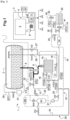
- FIG. 1 On the figure 1 is shown an embodiment of a station 1 for gravimetric distribution of a condensed gas in the liquid state.
- the gas condensed to the liquid state could be liquid air, liquid nitrogen or any other gas that is advantageous to store in condensed form to the liquid state.
- LNG liquefied natural gas
- GN gas phase of natural gas
- station 1 is designed to distribute LNG to one (or more) vehicle(s) equipped with a combustion engine running on LNG.
- vehicle is equipped with an on-board tank 40 (and therefore mobile) suitable for storing the LNG distributed to it.
- the tank is equipped with a fluid connection 41 through which the LNG is intended to be injected during distribution, and with a pneumatic connection 42 through which the NG vapors present in the tank are intended to be evacuated piecemeal by degassing during distribution (and, where applicable, before).
- station 1 includes a terminal 3 provided with a man-machine interface 4.
- the interface 4 includes a display screen 5, which can be touchscreen.
- the interface 5 can also include a card reader 6, associated with a keyboard 7.
- the keyboard 7 is in the form of a separate mechanical module, but it could be tactile and integrated into the screen 5.
- the V20 safety valve is manually operated.
- the sensors TT100, TT200, PT100 and PT200 and PT10 are connected to the automaton 11, which receives the measurements (of temperature or, respectively, of pressure) in real time or at any predefined period compatible with the performances (in particular the clock rate) of these sensors.
- the stationary tank 2 is preferably raised relative to the main distribution conduit, in particular to promote the flow of LNG from the tank towards the distribution circuit during the initial cooling of the distribution circuit.
- the tank is for example installed at a height (measured at its base) greater than or equal to 1.50 m.
- the filling circuit 9 comprises a filling conduit, which extends from a connection terminal A3 to a branch on the main conduit 13 between the isolation valve X3 and the safety valve V20, and a filling tap V1 manually operated, mounted on this filling conduit.
- the degassing circuit 10 comprises a pressure sensor PT2 and a temperature sensor TT5A, mounted on the main degassing conduit 19 between the degassing valve X6 and the connector 20.
- the GN In the degassing circuit 10, the GN is in the compressed state (but not condensed); its temperature varies depending on its pressure but it remains above -161°C.
- the X6, X15, B300 and B301 valves, through which the NG passes in the compressed state, are also cryogenic valves.
- the model of each valve can be chosen according to the gas temperature where the valve is located; for safety, we can also choose for the degassing circuit 10 valves capable of operating up to the temperature of the LNG (i.e. -161°C).
- the valve X6, in particular, the closest to the on-board tank 40 to be filled, must be able to operate at this temperature.
- the sensors TT5A and PT2 are connected to the automaton 11, which receives the measurements (of temperature or, respectively, of pressure) in real time or at any predefined period compatible with the performance (in particular the clock rate) of these sensors.
- station 1 also includes a recirculation circuit 24, which connects the distribution circuit 8, downstream of the flow meter FM and upstream of the final distribution valve X21, to the degassing circuit 10 downstream of the degassing valve X6.
- This recirculation circuit 24 includes a recirculation valve X20, connected to the automaton 11, which controls the opening or closing according to the progress of its program.
- Station 1 further comprises a main reinjection conduit 25, which extends from compressor 21, located upstream of the boil-off tank BO to stationary tank 2.
- This reinjection conduit 25 makes it possible to reinject the gas stored in the boil-off tank BO into the stationary tank 2.
- a double reinjection circuit is planned, making it possible to reinject the gas stored in the boil-off tank BO, i.e. in the upper part of tank 2 stationary, in other words directly in the gas phase, or in the lower part of the stationary tank 2, in other words directly in the liquid phase, depending on whether the reinjection in the gas phase or in the liquid phase of the NG will ensure that the pressure is maintained from the station always as close as possible to the target pressure, as will be explained later in the description.
- the main reinjection conduit 25 is split into a reinjection conduit 26 towards the upper part of the stationary reservoir 2, opening into the gas phase, and a reinjection conduit 27 towards the lower part of the stationary reservoir 2, opening into the gas phase. liquid.
- a first reinjection valve V24 is located on the reinjection conduit 26 towards the upper part of the stationary tank 2, downstream of the branch on the main reinjection conduit 25 and a second reinjection valve V22 is located on the conduit 27 of reinjection towards the lower part downstream of the branch on the main reinjection conduit 25.
- the valves V22 and V24 are connected to the automaton 11, which controls the opening and closing according to the progress of its program, so as to allow the gas stored in the boil-off tank VO to be reinjected either in the phase gaseous, or in the liquid phase.
- Station 1 also includes a pressurization circuit 28, which connects the lower part of tank 2 (where it is in communication with the liquid phase) to its upper part (where it is in communication with the gas phase).
- a pressurization valve V50 connected to the automaton 11, which controls its opening and closing.
- the pressurization circuit 28 is equipped with a pressure sensor PT1, mounted on the downstream section of the circuit 28, between the valve V50 and the connection of the circuit 28 on the upper part of the tank 2.
- the pressure sensor PT1 is connected to the automaton 11, which collects the measurements.
- the vapor pressure in the tank 2 is measured systematically (e.g.
- the pressurization valve V50 is kept closed.
- the pressurization valve V50 is opened and the LNG circulates in the pressurization circuit 28. As it heats up, the LNG vaporizes and thus increases the vapor pressure of the NG present in the stationary tank 2.
- the pressurization circuit 28 makes it possible to increase the pressure of the stationary tank 2 in the event of necessary, especially when the pressure becomes lower than the target pressure that has been set.
- the pressurization circuit 28 also preferably comprises a vaporizer 31.
- This particular arrangement makes it possible to optimally manage the rise in pressure in the stationary tank 2, before starting distribution or even during distribution. It is thus possible to vaporize condensed gas in the liquid state stored in the stationary tank 2 by circulating it in the vaporizer 31 of the pressurization circuit 28.
- the LNG thus vaporized is reinjected into the upper part of stationary tank 2 via circuit 28 and therefore, the vapor pressure of the NG present in tank 2 is increased.
- valve V50 is placed by the controller in the open state.
- the pressure rise circuit making it possible to manage the rise in pressure in the stationary tank 2 of the station could use the vaporizer 15, connected to the main conduit 13 of the distribution circuit and also used to ensure, if necessary, a thermal conditioning of LNG.
- the following valves are placed, on command from the automaton, in the following respective states (O meaning open and F meaning closed): [Table 1] Valve State X3 O V35 O V50 F V100 O V101 F V102 F V103 O X20 O X21 F X6 F X15 F B300 F B301 O V33 O V45 F V22 F V24 O
- Compressor 21 is stopped.
- the principle of the invention lies in the determination of an optimal target pressure for the stationary tank, which is calculated dynamically. More precisely, it is planned to permanently recalculate this optimal target pressure on which the pressure of the stationary tank 2 must be regulated, both between two fills, i.e. between two successive distribution cycles, but also during a distribution cycle. current, with the objective of guaranteeing the desired flow rate during a distribution cycle.
- the station 1 includes an additional circuit 29, making it possible to reduce the pressure in tank 2 of the station without degassing into the atmosphere.
- this additional circuit 29 comprises a depressurization conduit 30, which extends from the main reinjection conduit 25 downstream of the compressor 21 to the boil-off tank BO.
- a valve V33 for supplying the boil-off tank BO is located on the depressurization conduit 30, upstream of the boil-off tank BO and downstream of the junction of the depressurization conduit 30 with the main reinjection conduit 25 .
- a bypass valve V45 is mounted on the reinjection conduit 25, on the section downstream of the compressor 21 between the latter and the branch of the depressurization conduit 30.
- the valves V33 and V45 are connected to the controller 11, which controls the opening or closing according to the progress of its program.
- the gas phase of the stationary tank 2 of the station can be depressurized and recovered in the boil-off tank BO via the reinjection conduit 26 into the upper part of the stationary tank, the main conduit 25 reinjection and the depressurization conduit 30. Once recovered, this gas can be reinjected in the liquid phase, as explained previously.
- This double operation of recovering the overpressurized gas stored in the stationary tank 2 and reinjecting this recovered gas into the liquid phase of the tank 2 makes it possible to reduce the pressure of the stationary tank 2.
- the fact of reinjecting the gas into the phase liquid from the stationary tank 2 where it will condense will also cause an increase in the temperature of the liquid phase and therefore, a modification of the optimal target pressure value of the station.
- the effect of this double operation is to modify both the pressure in the stationary tank 2 and the target pressure to which the pressure of the stationary tank must be regulated. It is advantageously triggered by the automaton 11 only if the effect of the envisaged pressure reduction leads to reducing the difference between the target pressure and the pressure in the stationary tank.
- the target pressure in the stationary tank 2 corresponds to the pressure value that must be maintained in the stationary tank 2 to always have a sufficient pressure differential with the saturation pressure Psat in the on-board tank 40 making it possible to obtain the speed d the desired flow of LNG in the station's distribution circuit.
- LNG contains several hydrocarbon fractions.
- the composition of LNG can thus be noted as follows ⁇ x1, x2, x3, x4 ⁇ , where the parameters x1 to x4 correspond respectively to the fraction of methane, ethane, propane and butane present in the LNG. The heavier fractions are negligible.
- the saturation pressure Psat and the density of LNG can be estimated from its composition ⁇ x1, x2, x3, x4 ⁇ and its temperature.
- the temperature of the LNG varies along the distribution circuit 8, but by applying equation [1] to a distribution circuit reduced to a simplified model of an orifice, it is possible to obtain a sufficient approximation of the actual process .
- Pmax corresponds to the value of the maximum pressure reached in the on-board tank 40 of the vehicle during a first phase of the distribution cycle, occurring after the start of distribution, this first phase of the corresponding distribution cycle at a phase of initial increase in pressure in the on-board tank 40.
- the distribution gun 14 and the degassing connector 20 are connected respectively to the fluid connection 41 and to the pneumatic connection 42 of the on-board tank 40. These connections can be made manually by an unqualified operator, e.g. by the driver of the vehicle. Once the connections have been made and distribution authorized, the automaton 11 initiates a distribution cycle, which may include several successive distribution phases separated by intermediate degassing phases.
- the LNG flows from the stationary tank 2 to the on-board tank 40 via the distribution circuit 8, where the pressure P2 of the LNG undergoes a sudden increase.
- valve X20 of the recirculation circuit which puts the distribution circuit 8 in communication with the degassing circuit 10, itself in communication with the boil-off tank BO (at low pressure) via valve B301, which causes a pressure drop in distribution circuit 8.
- the pressure difference between it and the stationary tank 2 causes the LNG to flow from the stationary tank 2 towards the distribution circuit 8, then towards the degassing circuit 10.
- the automaton 11 can verify via the flow meter FM that the LNG is actually flowing into the distribution circuit 8.
- the GN from the boil-off tank BO is recompressed using compressor 21 and reinjected into stationary tank 2.
- the aforementioned states are maintained as long as the distribution circuit is not properly cooled. End of cooling detection is determined based on measurements provided by the circuit sensors. As soon as the end of cooling is detected, the valves X15, . Distribution can then be authorized.
- the maximum pressure Pmax likely to be reached in the on-board tank in the first phase of distribution will be estimated from temperature measurements carried out by the temperature sensors installed along the distribution circuit. distribution.
- the automaton 11 will be able to determine the degree of heating of the LNG during its flow in the distribution circuit and therefore, to determine the initial rise in pressure in the tank on board the first distribution phase and thus, to estimate the value Pmax, corresponding to the maximum pressure reached in this first phase.
- Pmargin defining the safety margin that we allow in relation to Pmax for determining the objective.
- Pmargin defining the safety margin that we allow in relation to Pmax for determining the objective.
- This optimal value of Pmargin is for example derived by statistical analysis of a fill-up history.
- the saturation pressure Psat of the LNG in the tank is estimated, before the start of distribution, on the basis of the composition of the LNG ⁇ x1, x2, x3, x4 ⁇ and the temperature of the LNG delivered to the on-board tank. From the temperature of the LNG delivered, we can estimate fairly precisely the temperature of the LNG in the on-board tank.
- the saturation pressure Psat is also estimated based on the LNG composition ⁇ x1, x2, x3, x4 ⁇ .
- the station's mass meter capable of providing a measurement of the mass of the LNG and therefore its density.
- an estimate of the composition of the LNG is determined based on pre-established temperature/density curves of the individual components of the LNG.
- the composition of the LNG is estimated by regression of the acquired temperature/density measurements on the temperature/density curves of the individual components.
- this target pressure Pobjective also depends on the pressure difference that must be maintained with the estimated value of the maximum pressure Pmax which will be reached in the on-board tank in the first phase of distribution.
- the pressure in the stationary tank 2 of the station increases due to the regasification of the LNG used to cool the circuit (as explained previously, the LNG is re-circulated and returned to the station when the circuit is cooled).
- the pressure in the station's stationary tank naturally drops.
- the station control mechanism can compensate for such a drop but cannot eliminate it.
- the adjustment variable ⁇ Padjust is then fixed, during refueling, on the basis of the refueling phase.
- the values to be assigned to ⁇ Padjust at each filling phase are estimated by regression from the measurements of the fillings previously carried out.
- the optimal target pressure is also constantly recalculated during a fill-up.
- ⁇ P corresponding to the difference between the pressure in the stationary tank 2 and the pressure in the on-board tank 40 on the vehicle, is measured during refueling.
- the flow rate Qv (or mass flow rate) is also measured.
- the LNG delivery temperature is also measured during refueling.
- the parameter K and the parameters x1,.., x4 defining the composition of the LNG are calculated and stored for later use.
- K Qv . Rho ⁇ P
- the measurements taken during a fill-up are used to update in real time the estimates made before the fill-up and thus update the optimal target pressure value for the station tank which was estimated before the fill-up.
- these measurements can be acquired via the sensor PT2, placed in the degassing circuit 10.
- connection of the degassing connector 20 to the pneumatic connection 42 of the on-board tank during a distribution cycle can be detected, according to an exemplary embodiment, from monitoring the pressure in the flexible conduit connected to the connector 20 which must be plugged in.
- This pressure monitoring can be carried out using measurements provided by the PT2 pressure sensor.
- the measurements of the pressure in the on-board tank 40 for updating the optimal target pressure value for the station tank can be acquired by the pressure sensor PT10, placed in the conduit flexible intended to be connected to the on-board tank 40, between the valve X21 and the distribution gun 14.
- This method of measuring the pressure of the on-board tank 40 can advantageously be used if the degassing connector is not connected. However, this implies that we close the valve X21 to be able to read the pressure on the PT10 sensor and therefore temporarily stop the distribution.
- the connection of the distribution gun 14 to the fluid connection 41 of the on-board tank during a distribution cycle can be detected from monitoring the pressure in the flexible conduit intended to be connected to the on-board tank 40. This monitoring of pressure can be carried out from the measurements provided by the PT10 pressure sensor.
- the principle described with reference to the detection of the connection of the degassing connector can therefore also be applied to detect and confirm the connection of the LNG distribution gun 14 to the fluid connection 41 of the on-board tank 40 of a vehicle, by implementing monitoring the pressure in the flexible conduit connected to the gun. This avoids having to add a dedicated sensor in the gun to confirm the connection.
- the pressure in the on-board tank must be estimated during refueling, to possibly allow adjustment of the optimal target pressure of the stationary tank estimated before the start of refueling, in accordance with the principles already explained for the estimation of this pressure before starting refueling.
- the station advantageously comprises a double reinjection circuit 26, 27, making it possible to reinject the gas stored in the boil-off tank BO, either in the gas phase or in the liquid phase of the on-board tank, this arrangement allows in particular improved management of the degassing phases of the on-board tank.
- the valve lower than a predetermined high threshold (condition verified by the automaton 11, which receives the measurement of the steam pressure from the PT2 sensor and is programmed to compare this pressure to the previously stored high threshold), the degassing valve X6 remains closed and the main distribution valve V35 remains open.
- the upper threshold is e.g. of approximately 11 bars.
- the automaton 11 controls the interruption of distribution by closing the main distribution valve V35, and the initiation of an intermediate degassing phase by opening the valve X6 degassing to reduce the vapor pressure in the on-board tank.
- the automaton 11 can control the opening of the vent valve X15 and the closing of the bypass valve B300 and the tank supply valve B301 Boil-off soundtrack.
- the steam (in gray) of GN present in the on-board tank 40 then escapes into the open air until it falls to a pressure (measured by the PT2 sensor and taken into account by the automaton 11) equal to or less than one low threshold, which triggers closing by the automaton 11 of the degassing valve X6.
- This degassing technique is however not desirable as it has the disadvantage of releasing natural gas into the atmosphere.
- the automaton 11 controls the maintenance of the vent valve X15 in the closed state, the maintenance of the valve B300 bypass in the closed state, and the opening of the B301 supply valve to the boil-off tank BO.
- the compressor 21 is started to compress the gas present in the boil-off tank BO and reinject it, via the reinjection conduit 25, into the stationary tank.
- the automaton 11 is adapted to control the reinjection of this gas, either into the gas phase (shaded) in the upper part of the stationary tank 2, via the reinjection conduit 26, or into the liquid phase ( in dotted lines) in the lower part of the stationary tank, via the reinjection conduit 27, by appropriate control of the opening and closing states of the corresponding valves V24 and V22 mounted in these reinjection conduits.
- the gas stored in the boil-off tank BO can also come from the stationary tank 2 itself via circuit 29, if the pressure in the stationary tank 2 must be reduced.
- the controller 11 will determine whether the degassing recovered in the boil-off tank BO must be reinjected in the gas phase or in the liquid phase into the stationary tank 2, depending on whether the reinjection in the gas phase or in the liquid phase will have the effect of keeping the pressure of the station closest to the determined optimal target pressure.
- the choice controlled by the automaton 11 to reinject the gas from the boil-off tank BO either in the gas phase or in the liquid phase into the stationary tank 2 depends on the result of one or the other of this action in favor of restoring the equilibrium of the vapor pressure without the stationary tank (systematically measured by means of the sensor PT1) in relation to the optimal target pressure Pobjective. This arrangement therefore makes it possible to keep the pressure in the stationary tank always as close as possible to the optimal target pressure Pobjective.
Landscapes
- Engineering & Computer Science (AREA)
- Mechanical Engineering (AREA)
- General Engineering & Computer Science (AREA)
- Filling Or Discharging Of Gas Storage Vessels (AREA)
Claims (10)
- Verfahren zur Verwaltung einer Station (1) zum gravimetrischen Zapfen von kondensiertem Gas in flüssigem Zustand, wobei die Station einen stationären Speichertank (2), einen Zapfkreis (8), der mit dem stationären Tank verbunden und mit einem Zapfventil (X21) und einer Zapfpistole (14) für den Anschluss an einen bordeigenen Tank (40) an einem Fahrzeug versehen ist, einen Entgasungskreis (10), der mit einem Entgasungsventil (X6) und einem Entgasungsverbinder (20) für den Anschluss an den bordeigenen Tank versehen ist, umfasst, wobei das Verfahren eine Regelung des Dampfdrucks im stationären Tank auf einen Zieldruck (PZiel) umfasst, die es ermöglicht, den Dampfdruck im stationären Tank zu steuern, um bei einem Zapfzyklus, bei dem der bordeigene Tank mit dem Zapfkreis verbunden ist, eine Druckdifferenz (ΔP) zwischen dem stationären Tank und dem bordeigenen Tank zu halten, sodass das kondensierte Gas in flüssigem Zustand mit einer vorbestimmten Schwerkraftströmungsrate vom stationären Tank zum bordeigenen Tank strömen kann, wobei das Verfahren dadurch gekennzeichnet ist, dass es vor dem Start eines Zapfzyklus Schritte umfasst des:Schätzens, auf Grundlage von Temperaturmessungen entlang des Zapfkreises (8), eines ersten Druckwerts (Pmax), der einem Druckmaximum entspricht, das im Laufe einer ersten Phase der Erhöhung des Drucks des Zapfzyklus nach dessen Start im bordeigenen Tank (40) erreicht wird;Schätzens, auf Grundlage der Temperatur des kondensierten Gases in flüssigem Zustand, das in den bordeigenen Tank abgegeben wird, und der Zusammensetzung des kondensierten Gases in flüssigem Zustand, eines zweiten Druckwerts, der dem Sättigungsdruck (Psat) entspricht, der im Laufe einer zweiten Phase der Stabilisierung des Drucks im Anschluss an die erste Phase des Zapfzyklus im bordeigenen Tank erreicht wird;wobei der Zieldruck (PZiel) des stationären Tanks zwischen zwei aufeinanderfolgenden Zapfzyklen fortlaufend in Abhängigkeit von der Schätzung des ersten und des zweiten Druckwerts berechnet wird.
- Verfahren nach Anspruch 1, dadurch gekennzeichnet, dass während eines Zapfzyklus der vor dem Start des Zapfzyklus berechnete Zieldruck (PZiel) aktualisiert wird.
- Verfahren nach Anspruch 2, dadurch gekennzeichnet, dass während eines Zapfzyklus Messungen des Drucks im bordeigenen Tank (40) erfasst, der erste und der zweite Druckwert, die vor dem Start des Zapfzyklus geschätzt wurden, auf Grundlage der erfassten Druckmessungen aktualisiert und der Zieldruck (PZiel) auf Grundlage des ersten und des zweiten aktualisierten Druckwerts aktualisiert werden.
- Verfahren nach Anspruch 3, dadurch gekennzeichnet, dass beim Zapfzyklus die Aktualisierung des ersten und des zweiten Druckwerts an das vorhergehende Erkennen des Anschlusses des Entgasungsverbinders (20) des Entgasungskreises und/oder der Zapfpistole (14) an den bordeigenen Tank (40) geknüpft ist.
- Verfahren nach einem der vorstehenden Ansprüche, dadurch gekennzeichnet, dass es während eines Zapfzyklus mindestens eine Entgasungsphase umfasst, bei der Dampf aus dem bordeigenen Tank (40) in einen Boil-off- (BO-) Tank der Station eingespritzt wird, wobei die Regelung des Drucks des stationären Tanks (2) auf den Zieldruck (PZiel) das Wiedereinspritzen des im Boil-off- (BO) Tank gespeicherten Gases in Abhängigkeit von einer Schätzung der Temperatur des Gases in flüssigem Zustand im stationären Tank und des Dampfdrucks im stationären Tank entweder in die Gasphase des stationären Tanks oder in die kondensierte Phase in flüssigem Zustand des stationären Tanks umfasst.
- Verfahren nach einem der vorstehenden Ansprüche, dadurch gekennzeichnet, dass es während eines Zapfzyklus das Messen des Dampfdrucks im stationären Tank umfasst, und, wenn der Dampfdruck eine vorbestimmte obere Schwelle erreicht, es eine Phase des Entgasens des stationären Tanks umfasst, bei der Dampf aus dem stationären Tank (2) in einen Boil-off- (BO-) Tank der Station eingespritzt wird.
- Verfahren nach Anspruch 6, dadurch gekennzeichnet, dass es das Rekondensieren des im Boil-off-Tank gespeicherten Gases mittels eines Verdichters und das Wiedereinspritzen des rekondensierten Gases in die flüssige Phase des stationären Tanks umfasst.
- Station (1) zum gravimetrischen Zapfen von kondensiertem Gas in flüssigem Zustand, die einen stationären Speichertank (2), einen Zapfkreis (8), der mit dem stationären Tank (2) verbunden und mit einem Zapfventil (X21) und einer Zapfpistole (14) für den Anschluss an einen bordeigenen Tank (40) an einem Fahrzeug versehen ist, einen Entgasungskreis (10), der mit einem Entgasungsventil (X6) und einem Entgasungsverbinder (20) für den Anschluss an den bordeigenen Tank (40) versehen ist, umfasst, wobei der Entgasungskreis (10) mit einem Boil-off- (BO-) Tank der Station verbunden ist, wobei diese Station eine programmierbare Steuerung (11), die mit den Ventilen des Zapfkreises und des Entgasungskreises verbunden ist, um einen Zapfzyklus zu steuern, sowie Temperatursensoren, die entlang des Zapfkreises platziert sind, und Mittel zum Bestimmen der Zusammensetzung des Kältemittels auf Grundlage der Messung seiner Masse umfasst, wobei diese Station dadurch gekennzeichnet ist, dass die programmierbare Steuerung (11) zur Umsetzung des Verfahrens nach einem der vorstehenden Ansprüche geeignet ist.
- Station nach Anspruch 8, dadurch gekennzeichnet, dass sie einen zusätzlichen Kreis (29) umfasst, der sich zwischen dem stationären Tank (2) und dem Boil-off- (BO-) Tank erstreckt, wobei die Steuerung (11) mit Ventilen dieses zusätzlichen Kreises verbunden und dafür geeignet ist, die Druckentlastung der Gasphase des stationären Tanks (2) durch diesen zusätzlichen Kreis (29) und das Rückführen des Gases aus dem stationären Tank in den Boil-off- (BO-) Tank zu steuern, um den Druck des stationären Tanks auf dem Zieldruck (PZiel) zu halten.
- Station nach Anspruch 8 oder 9, dadurch gekennzeichnet, dass sie einen Kreis zum Wiedereinspritzen des im Boil-off- (BO-) Tank gespeicherten Gases in den stationären Tank (2) umfasst, wobei der Wiedereinspritzkreis eine erste Wiedereinspritzleitung (26), die sich vom Boil-off-Tank zum oberen Teil des stationären Tanks erstreckt und in die Gasphase des stationären Tanks mündet, und eine zweite Wiedereinspritzleitung (27) umfasst, die sich vom Boil-off-Tank zum unteren Teil des stationären Tanks erstreckt und in die flüssige Phase des stationären Tanks mündet, wobei die programmierbare Steuerung (11) geeignet ist, das Wiedereinspritzen des im Boil-off- (BO-) Tank gespeicherten Gases in Abhängigkeit von der Temperatur des kondensierten Gases in flüssigem Zustand und des Drucks im stationären Tank entweder in die flüssige Phase oder in die Gasphase des stationären Tanks zu steuern, um den Druck des stationären Tanks auf dem Zieldruck zu halten.
Applications Claiming Priority (1)
| Application Number | Priority Date | Filing Date | Title |
|---|---|---|---|
| FR1909298A FR3100032B1 (fr) | 2019-08-20 | 2019-08-20 | Station de distribution gravimétrique de gaz condensé à l’état liquide et procédé de gestion d’une telle station |
Publications (3)
| Publication Number | Publication Date |
|---|---|
| EP3786514A1 EP3786514A1 (de) | 2021-03-03 |
| EP3786514B1 true EP3786514B1 (de) | 2024-03-27 |
| EP3786514C0 EP3786514C0 (de) | 2024-03-27 |
Family
ID=68733344
Family Applications (1)
| Application Number | Title | Priority Date | Filing Date |
|---|---|---|---|
| EP20191763.0A Active EP3786514B1 (de) | 2019-08-20 | 2020-08-19 | Station zur gravimetrischen verteilung von kondensiertem gas in flüssigem zustand, und verfahren zum betrieb einer solchen station |
Country Status (2)
| Country | Link |
|---|---|
| EP (1) | EP3786514B1 (de) |
| FR (1) | FR3100032B1 (de) |
Families Citing this family (1)
| Publication number | Priority date | Publication date | Assignee | Title |
|---|---|---|---|---|
| US12270514B1 (en) | 2022-12-07 | 2025-04-08 | United Launch Alliance, L.L.C. | Methods and systems to determine liquid natural gas (LNG) composition and density |
Family Cites Families (5)
| Publication number | Priority date | Publication date | Assignee | Title |
|---|---|---|---|---|
| DE102006031000A1 (de) * | 2006-07-05 | 2008-01-17 | Bayerische Motoren Werke Ag | Verfahren zum Betrieb einer Vorrichtung zur Befüllung eines Behälters mit kryogen gespeichertem Kraftstoff |
| US9181077B2 (en) | 2013-01-22 | 2015-11-10 | Linde Aktiengesellschaft | Methods for liquefied natural gas fueling |
| FR3041951B1 (fr) * | 2015-10-05 | 2020-09-04 | Cryostar Sas | Procede de delivrance de liquide cryogenique et installation pour la mise en oeuvre de ce procede |
| FR3041624B1 (fr) * | 2016-04-13 | 2018-01-26 | Axegaz | Procede et station automatises de distribution gravimetrique de gaz condense a l’etat liquide |
| EP3232113A1 (de) | 2016-04-13 | 2017-10-18 | Axegaz | Automatisiertes verfahren und automatisierte station zur gravimetrischen verteilung von kondensiertem gas in flüssigzustand |
-
2019
- 2019-08-20 FR FR1909298A patent/FR3100032B1/fr active Active
-
2020
- 2020-08-19 EP EP20191763.0A patent/EP3786514B1/de active Active
Also Published As
| Publication number | Publication date |
|---|---|
| FR3100032B1 (fr) | 2021-09-10 |
| EP3786514C0 (de) | 2024-03-27 |
| EP3786514A1 (de) | 2021-03-03 |
| FR3100032A1 (fr) | 2021-02-26 |
Similar Documents
| Publication | Publication Date | Title |
|---|---|---|
| US11441736B2 (en) | Multi-vessel fluid storage and delivery system | |
| KR102330773B1 (ko) | 선박 | |
| EP2191190B1 (de) | Verfahren zum füllen eines druckgastanks | |
| EP3851731B1 (de) | Station und verfahren zum füllen von behältern | |
| FR2971011A1 (fr) | Systeme pour reguler l'alimentation en combustible d'un moteur a turbine a gaz. | |
| EP3271637B1 (de) | Verfahren zum füllen von tanks mit unter druck stehendem gas | |
| EP1596122A2 (de) | Anlage zur Abgabe von brennbaren Gas zur Antrieb eines Boates für den Transport von flüssigen Gasen | |
| WO2014177796A2 (fr) | Procédé et dispositif de ravitaillement en liquide cryogénique, notamment en gaz naturel liquéfié | |
| KR20200047623A (ko) | 선박 | |
| FR3093785A1 (fr) | Système de contrôle de pression dans une cuve de gaz naturel liquéfié. | |
| EP3786514B1 (de) | Station zur gravimetrischen verteilung von kondensiertem gas in flüssigem zustand, und verfahren zum betrieb einer solchen station | |
| FR3041624A1 (fr) | Procede et station automatises de distribution gravimetrique de gaz condense a l’etat liquide | |
| KR102316444B1 (ko) | 선박 및 lpg 온도/압력 관리 방법 | |
| KR102303751B1 (ko) | 선박 | |
| EP3232113A1 (de) | Automatisiertes verfahren und automatisierte station zur gravimetrischen verteilung von kondensiertem gas in flüssigzustand | |
| EP3359867B1 (de) | Verfahren zur zuführung einer kryogenen flüssigkeit und einrichtung zur umsetzung des besagten verfahrens | |
| EP1511965B1 (de) | Verfahren und anlage zum steuern mindestens eines kryogenen zentrifugalkompressors, druckleitung | |
| WO2019057541A1 (fr) | Dispositif et procede d'alimentation en gaz a indice de methane optimise d'au moins un moteur thermique, en particulier d'un navire de transport de gaz liquefie | |
| FR2989147A1 (fr) | Procede et dispositif de remplissage d'un reservoir de gaz sous pression | |
| WO2019049789A1 (ja) | 船舶 | |
| EP3046788B1 (de) | Verfahren zur verwaltung des betriebs eines kühlwagens zum transport von wärmeempfindlichen produkten durch modifizierung der kälteleistung | |
| FR3166666A1 (fr) | Systeme d’alimentation en hydrogene d’une turbomachine et dispositif de regulation en temperature d’un tel systeme d’alimentation en hydrogene |
Legal Events
| Date | Code | Title | Description |
|---|---|---|---|
| PUAI | Public reference made under article 153(3) epc to a published international application that has entered the european phase |
Free format text: ORIGINAL CODE: 0009012 |
|
| STAA | Information on the status of an ep patent application or granted ep patent |
Free format text: STATUS: THE APPLICATION HAS BEEN PUBLISHED |
|
| AK | Designated contracting states |
Kind code of ref document: A1 Designated state(s): AL AT BE BG CH CY CZ DE DK EE ES FI FR GB GR HR HU IE IS IT LI LT LU LV MC MK MT NL NO PL PT RO RS SE SI SK SM TR |
|
| AX | Request for extension of the european patent |
Extension state: BA ME |
|
| STAA | Information on the status of an ep patent application or granted ep patent |
Free format text: STATUS: REQUEST FOR EXAMINATION WAS MADE |
|
| 17P | Request for examination filed |
Effective date: 20210831 |
|
| RBV | Designated contracting states (corrected) |
Designated state(s): AL AT BE BG CH CY CZ DE DK EE ES FI FR GB GR HR HU IE IS IT LI LT LU LV MC MK MT NL NO PL PT RO RS SE SI SK SM TR |
|
| GRAP | Despatch of communication of intention to grant a patent |
Free format text: ORIGINAL CODE: EPIDOSNIGR1 |
|
| STAA | Information on the status of an ep patent application or granted ep patent |
Free format text: STATUS: GRANT OF PATENT IS INTENDED |
|
| INTG | Intention to grant announced |
Effective date: 20231009 |
|
| GRAS | Grant fee paid |
Free format text: ORIGINAL CODE: EPIDOSNIGR3 |
|
| GRAA | (expected) grant |
Free format text: ORIGINAL CODE: 0009210 |
|
| STAA | Information on the status of an ep patent application or granted ep patent |
Free format text: STATUS: THE PATENT HAS BEEN GRANTED |
|
| RAP3 | Party data changed (applicant data changed or rights of an application transferred) |
Owner name: AXEGAZ TRADING AND TECHNOLOGIES |
|
| AK | Designated contracting states |
Kind code of ref document: B1 Designated state(s): AL AT BE BG CH CY CZ DE DK EE ES FI FR GB GR HR HU IE IS IT LI LT LU LV MC MK MT NL NO PL PT RO RS SE SI SK SM TR |
|
| REG | Reference to a national code |
Ref country code: GB Ref legal event code: FG4D Free format text: NOT ENGLISH |
|
| REG | Reference to a national code |
Ref country code: CH Ref legal event code: EP |
|
| REG | Reference to a national code |
Ref country code: DE Ref legal event code: R096 Ref document number: 602020027816 Country of ref document: DE |
|
| REG | Reference to a national code |
Ref country code: IE Ref legal event code: FG4D Free format text: LANGUAGE OF EP DOCUMENT: FRENCH |
|
| U01 | Request for unitary effect filed |
Effective date: 20240423 |
|
| U07 | Unitary effect registered |
Designated state(s): AT BE BG DE DK EE FI FR IT LT LU LV MT NL PT SE SI Effective date: 20240429 |
|
| PG25 | Lapsed in a contracting state [announced via postgrant information from national office to epo] |
Ref country code: GR Free format text: LAPSE BECAUSE OF FAILURE TO SUBMIT A TRANSLATION OF THE DESCRIPTION OR TO PAY THE FEE WITHIN THE PRESCRIBED TIME-LIMIT Effective date: 20240628 |
|
| PG25 | Lapsed in a contracting state [announced via postgrant information from national office to epo] |
Ref country code: RS Free format text: LAPSE BECAUSE OF FAILURE TO SUBMIT A TRANSLATION OF THE DESCRIPTION OR TO PAY THE FEE WITHIN THE PRESCRIBED TIME-LIMIT Effective date: 20240627 Ref country code: HR Free format text: LAPSE BECAUSE OF FAILURE TO SUBMIT A TRANSLATION OF THE DESCRIPTION OR TO PAY THE FEE WITHIN THE PRESCRIBED TIME-LIMIT Effective date: 20240327 |
|
| PG25 | Lapsed in a contracting state [announced via postgrant information from national office to epo] |
Ref country code: RS Free format text: LAPSE BECAUSE OF FAILURE TO SUBMIT A TRANSLATION OF THE DESCRIPTION OR TO PAY THE FEE WITHIN THE PRESCRIBED TIME-LIMIT Effective date: 20240627 Ref country code: NO Free format text: LAPSE BECAUSE OF FAILURE TO SUBMIT A TRANSLATION OF THE DESCRIPTION OR TO PAY THE FEE WITHIN THE PRESCRIBED TIME-LIMIT Effective date: 20240627 Ref country code: HR Free format text: LAPSE BECAUSE OF FAILURE TO SUBMIT A TRANSLATION OF THE DESCRIPTION OR TO PAY THE FEE WITHIN THE PRESCRIBED TIME-LIMIT Effective date: 20240327 Ref country code: GR Free format text: LAPSE BECAUSE OF FAILURE TO SUBMIT A TRANSLATION OF THE DESCRIPTION OR TO PAY THE FEE WITHIN THE PRESCRIBED TIME-LIMIT Effective date: 20240628 |
|
| U20 | Renewal fee for the european patent with unitary effect paid |
Year of fee payment: 5 Effective date: 20240821 |
|
| PG25 | Lapsed in a contracting state [announced via postgrant information from national office to epo] |
Ref country code: IS Free format text: LAPSE BECAUSE OF FAILURE TO SUBMIT A TRANSLATION OF THE DESCRIPTION OR TO PAY THE FEE WITHIN THE PRESCRIBED TIME-LIMIT Effective date: 20240727 |
|
| PG25 | Lapsed in a contracting state [announced via postgrant information from national office to epo] |
Ref country code: SM Free format text: LAPSE BECAUSE OF FAILURE TO SUBMIT A TRANSLATION OF THE DESCRIPTION OR TO PAY THE FEE WITHIN THE PRESCRIBED TIME-LIMIT Effective date: 20240327 |
|
| PG25 | Lapsed in a contracting state [announced via postgrant information from national office to epo] |
Ref country code: ES Free format text: LAPSE BECAUSE OF FAILURE TO SUBMIT A TRANSLATION OF THE DESCRIPTION OR TO PAY THE FEE WITHIN THE PRESCRIBED TIME-LIMIT Effective date: 20240327 |
|
| PG25 | Lapsed in a contracting state [announced via postgrant information from national office to epo] |
Ref country code: CZ Free format text: LAPSE BECAUSE OF FAILURE TO SUBMIT A TRANSLATION OF THE DESCRIPTION OR TO PAY THE FEE WITHIN THE PRESCRIBED TIME-LIMIT Effective date: 20240327 |
|
| PG25 | Lapsed in a contracting state [announced via postgrant information from national office to epo] |
Ref country code: PL Free format text: LAPSE BECAUSE OF FAILURE TO SUBMIT A TRANSLATION OF THE DESCRIPTION OR TO PAY THE FEE WITHIN THE PRESCRIBED TIME-LIMIT Effective date: 20240327 |
|
| PG25 | Lapsed in a contracting state [announced via postgrant information from national office to epo] |
Ref country code: SK Free format text: LAPSE BECAUSE OF FAILURE TO SUBMIT A TRANSLATION OF THE DESCRIPTION OR TO PAY THE FEE WITHIN THE PRESCRIBED TIME-LIMIT Effective date: 20240327 |
|
| PG25 | Lapsed in a contracting state [announced via postgrant information from national office to epo] |
Ref country code: SM Free format text: LAPSE BECAUSE OF FAILURE TO SUBMIT A TRANSLATION OF THE DESCRIPTION OR TO PAY THE FEE WITHIN THE PRESCRIBED TIME-LIMIT Effective date: 20240327 Ref country code: SK Free format text: LAPSE BECAUSE OF FAILURE TO SUBMIT A TRANSLATION OF THE DESCRIPTION OR TO PAY THE FEE WITHIN THE PRESCRIBED TIME-LIMIT Effective date: 20240327 Ref country code: RO Free format text: LAPSE BECAUSE OF FAILURE TO SUBMIT A TRANSLATION OF THE DESCRIPTION OR TO PAY THE FEE WITHIN THE PRESCRIBED TIME-LIMIT Effective date: 20240327 Ref country code: PL Free format text: LAPSE BECAUSE OF FAILURE TO SUBMIT A TRANSLATION OF THE DESCRIPTION OR TO PAY THE FEE WITHIN THE PRESCRIBED TIME-LIMIT Effective date: 20240327 Ref country code: IS Free format text: LAPSE BECAUSE OF FAILURE TO SUBMIT A TRANSLATION OF THE DESCRIPTION OR TO PAY THE FEE WITHIN THE PRESCRIBED TIME-LIMIT Effective date: 20240727 Ref country code: ES Free format text: LAPSE BECAUSE OF FAILURE TO SUBMIT A TRANSLATION OF THE DESCRIPTION OR TO PAY THE FEE WITHIN THE PRESCRIBED TIME-LIMIT Effective date: 20240327 Ref country code: CZ Free format text: LAPSE BECAUSE OF FAILURE TO SUBMIT A TRANSLATION OF THE DESCRIPTION OR TO PAY THE FEE WITHIN THE PRESCRIBED TIME-LIMIT Effective date: 20240327 |
|
| REG | Reference to a national code |
Ref country code: DE Ref legal event code: R097 Ref document number: 602020027816 Country of ref document: DE |
|
| PLBE | No opposition filed within time limit |
Free format text: ORIGINAL CODE: 0009261 |
|
| STAA | Information on the status of an ep patent application or granted ep patent |
Free format text: STATUS: NO OPPOSITION FILED WITHIN TIME LIMIT |
|
| 26N | No opposition filed |
Effective date: 20250103 |
|
| REG | Reference to a national code |
Ref country code: CH Ref legal event code: PL |
|
| GBPC | Gb: european patent ceased through non-payment of renewal fee |
Effective date: 20240819 |
|
| PG25 | Lapsed in a contracting state [announced via postgrant information from national office to epo] |
Ref country code: MC Free format text: LAPSE BECAUSE OF FAILURE TO SUBMIT A TRANSLATION OF THE DESCRIPTION OR TO PAY THE FEE WITHIN THE PRESCRIBED TIME-LIMIT Effective date: 20240327 Ref country code: CH Free format text: LAPSE BECAUSE OF NON-PAYMENT OF DUE FEES Effective date: 20240831 |
|
| PG25 | Lapsed in a contracting state [announced via postgrant information from national office to epo] |
Ref country code: GB Free format text: LAPSE BECAUSE OF NON-PAYMENT OF DUE FEES Effective date: 20240819 |
|
| PG25 | Lapsed in a contracting state [announced via postgrant information from national office to epo] |
Ref country code: IE Free format text: LAPSE BECAUSE OF NON-PAYMENT OF DUE FEES Effective date: 20240819 |
|
| U20 | Renewal fee for the european patent with unitary effect paid |
Year of fee payment: 6 Effective date: 20250717 |
|
| PG25 | Lapsed in a contracting state [announced via postgrant information from national office to epo] |
Ref country code: CY Free format text: LAPSE BECAUSE OF FAILURE TO SUBMIT A TRANSLATION OF THE DESCRIPTION OR TO PAY THE FEE WITHIN THE PRESCRIBED TIME-LIMIT; INVALID AB INITIO Effective date: 20200819 |
|
| PG25 | Lapsed in a contracting state [announced via postgrant information from national office to epo] |
Ref country code: HU Free format text: LAPSE BECAUSE OF FAILURE TO SUBMIT A TRANSLATION OF THE DESCRIPTION OR TO PAY THE FEE WITHIN THE PRESCRIBED TIME-LIMIT; INVALID AB INITIO Effective date: 20200819 |