EP3786526B1 - Kochvorrichtung - Google Patents
Kochvorrichtung Download PDFInfo
- Publication number
- EP3786526B1 EP3786526B1 EP19791561.4A EP19791561A EP3786526B1 EP 3786526 B1 EP3786526 B1 EP 3786526B1 EP 19791561 A EP19791561 A EP 19791561A EP 3786526 B1 EP3786526 B1 EP 3786526B1
- Authority
- EP
- European Patent Office
- Prior art keywords
- heating chamber
- illuminator
- top panel
- disposed
- opening
- Prior art date
- Legal status (The legal status is an assumption and is not a legal conclusion. Google has not performed a legal analysis and makes no representation as to the accuracy of the status listed.)
- Active
Links
Images



Classifications
-
- F—MECHANICAL ENGINEERING; LIGHTING; HEATING; WEAPONS; BLASTING
- F24—HEATING; RANGES; VENTILATING
- F24C—DOMESTIC STOVES OR RANGES ; DETAILS OF DOMESTIC STOVES OR RANGES, OF GENERAL APPLICATION
- F24C15/00—Details
- F24C15/008—Illumination for oven cavities
-
- F—MECHANICAL ENGINEERING; LIGHTING; HEATING; WEAPONS; BLASTING
- F24—HEATING; RANGES; VENTILATING
- F24C—DOMESTIC STOVES OR RANGES ; DETAILS OF DOMESTIC STOVES OR RANGES, OF GENERAL APPLICATION
- F24C15/00—Details
- F24C15/004—Windows not in a door
-
- F—MECHANICAL ENGINEERING; LIGHTING; HEATING; WEAPONS; BLASTING
- F24—HEATING; RANGES; VENTILATING
- F24C—DOMESTIC STOVES OR RANGES ; DETAILS OF DOMESTIC STOVES OR RANGES, OF GENERAL APPLICATION
- F24C7/00—Stoves or ranges heated by electric energy
- F24C7/04—Stoves or ranges heated by electric energy with heat radiated directly from the heating element
- F24C7/046—Ranges
-
- F—MECHANICAL ENGINEERING; LIGHTING; HEATING; WEAPONS; BLASTING
- F24—HEATING; RANGES; VENTILATING
- F24C—DOMESTIC STOVES OR RANGES ; DETAILS OF DOMESTIC STOVES OR RANGES, OF GENERAL APPLICATION
- F24C7/00—Stoves or ranges heated by electric energy
- F24C7/08—Arrangement or mounting of control or safety devices
- F24C7/082—Arrangement or mounting of control or safety devices on ranges, e.g. control panels, illumination
- F24C7/085—Arrangement or mounting of control or safety devices on ranges, e.g. control panels, illumination on baking ovens
-
- H—ELECTRICITY
- H05—ELECTRIC TECHNIQUES NOT OTHERWISE PROVIDED FOR
- H05B—ELECTRIC HEATING; ELECTRIC LIGHT SOURCES NOT OTHERWISE PROVIDED FOR; CIRCUIT ARRANGEMENTS FOR ELECTRIC LIGHT SOURCES, IN GENERAL
- H05B6/00—Heating by electric, magnetic or electromagnetic fields
- H05B6/64—Heating using microwaves
- H05B6/6444—Aspects relating to lighting devices in the microwave cavity
-
- H—ELECTRICITY
- H05—ELECTRIC TECHNIQUES NOT OTHERWISE PROVIDED FOR
- H05B—ELECTRIC HEATING; ELECTRIC LIGHT SOURCES NOT OTHERWISE PROVIDED FOR; CIRCUIT ARRANGEMENTS FOR ELECTRIC LIGHT SOURCES, IN GENERAL
- H05B6/00—Heating by electric, magnetic or electromagnetic fields
- H05B6/64—Heating using microwaves
- H05B6/6447—Method of operation or details of the microwave heating apparatus related to the use of detectors or sensors
-
- F—MECHANICAL ENGINEERING; LIGHTING; HEATING; WEAPONS; BLASTING
- F24—HEATING; RANGES; VENTILATING
- F24C—DOMESTIC STOVES OR RANGES ; DETAILS OF DOMESTIC STOVES OR RANGES, OF GENERAL APPLICATION
- F24C7/00—Stoves or ranges heated by electric energy
- F24C7/02—Stoves or ranges heated by electric energy using microwaves
Definitions
- the present invention relates to a heating cooking device for heating food.
- That heating cooking device including an imaging unit to image inside of the chamber (for example, see PTL 1).
- That heating cooking device includes, on a ceiling of a heating chamber, an imaging unit to capture an image, and the heating cooking device further includes an illuminator to increase an amount of light for stable imaging.
- another configuration may be considered in which the inside of the chamber is illuminated only with an illuminator on a side wall to avoid the illumination from the ceiling.
- an illuminator on a side wall to avoid the illumination from the ceiling.
- a heating cooking device in the present disclosure includes a heating chamber having a front face opening on a front face of the heating chamber, an upper wall disposed on an upper part of the heating chamber, a left-side wall disposed on a left-side part of the heating chamber, a right-side wall disposed on a right-side part of the heating chamber, a back wall disposed on a rear part of the heating chamber and a bottom wall disposed on a lower part of the heating chamber; a heater configured to heat an object to be heated stored in the heating chamber; a camera that has an optical axis and is disposed on the upper wall of the heating chamber to face inside of the heating chamber; and a first illuminator arranged on an upper side of the upper wall and configured to radiate light toward the inside of the heating chamber; the heating cooking device further comprises a top panel disposed below the upper wall of the heating chamber, the top panel including a semitransparent member configured to diffuse the light from the first illuminator to illuminate downward, and the top panel including a top panel opening serving
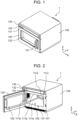
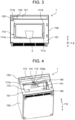
- FIGS. 1 to 17 each show a heating cooking device according to the invention.
- heating cooking device 1 has; chassis 100; heating chamber 110 disposed in chassis 100; and door 120 openably covering front face opening 102 located on front frame 101 serving as a front face of chassis 100.
- a side of front face opening 102 of heating cooking device 1 is assumed to be a front side, and a back face side, which is the opposite side, is assumed to be a rear side. Further, when viewed from the front side, in other words, in a front view, a top surface side of heating cooking device 1 is assumed to be an upper side, and a bottom face side is assumed to be a lower side. Further, in the front view, a right direction from heating cooking device 1 is assumed to be a right side, and a left direction is assumed to be a left side.
- heating cooking device 1 In the front view of heating cooking device 1, the right direction is assumed to be X direction, and the left direction is assumed to be -X direction. A rear direction and a front direction of heating cooking device 1 are respectively assumed to be Y direction and -Y direction. An upper direction and a lower direction of heating cooking device 1 are respectively assumed to be Z direction and -Z direction.
- Heating chamber 110 has: upper wall 111a disposed on an upper part of heating chamber 110; left-side wall 111b and right-side wall 111c each disposed on one of both parts on the right and left of heating chamber 110; back wall 111d disposed on a rear part of heating chamber 110; and bottom wall 111e disposed on a lower part of heating chamber 110.
- heating chamber 110 there is formed a space.
- Door 120 is attached to chassis 100 on the left side of front face opening 102 in an openable manner about a rotation center in the vertical direction.
- Door 120 has handle 121 on a right end part of a front surface of door 120.
- handle 121 is pulled by a user, door 120 is rotationally operated, and front face opening 102 is opened. Further, when handle 121 is pushed by a user, front face opening 102 is closed.
- Door 120 is provided with glass window 122 through which a user can check condition in heating chamber 110.
- Heating cooking device 1 supplies at least one of microwaves (high-frequency waves), radiation heat, hot air, and steam to the inside of heating chamber 110 to heat an object to be heated placed on a bottom part of heating chamber 110.
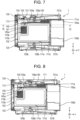
- heating cooking device 1 includes as a heater serving as a heating means at least one of the followings: a high-frequency wave generator including magnetrons 106a, 106b to generate microwaves (see FIGS. 7 and 8 ); an upper heater unit (not shown) to heat, by radiation heat, an object to be heated; a convection heater unit (not shown) to circulate hot air in heating chamber 110; and a steam generator (not shown) to generate steam in heating chamber 110.
- a high-frequency wave generator including magnetrons 106a, 106b to generate microwaves (see FIGS. 7 and 8 ); an upper heater unit (not shown) to heat, by radiation heat, an object to be heated; a convection heater unit (not shown) to circulate hot air in heating chamber 110; and a steam generator (not shown) to generate steam in heating
- wall surface opening 112 as an opening.
- Wall surface depression 113 formed in a recessed shape is provided upward from a circumferential edge of wall surface opening 112.
- Wall surface depression 113 is formed in a recessed shape obliquely upward from the circumferential edge of wall surface opening 112 provided in upper wall 111a of heating chamber 110.
- depression bottom opening 114 that is an opening for imaging.
- a side wall of wall surface depression 113 has a tapered shape that is narrower toward wall surface opening 112 from heating chamber 110.
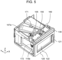
- FIG. 5 is a perspective view showing heating cooking device 1 according to the one aspect of the present disclosure with an upper face and a side face of chassis 100 removed.
- FIG. 6 is a top view showing heating cooking device 1 according to the one aspect of the present disclosure with the upper face and the side face of chassis 100 removed.
- magnetrons 106a, 106b are each provided on one of an upper part and a lower part on the rear part of heating cooking device 1.
- Magnetrons 106a, 106b are respectively connected to waveguides 107a, 107b that transfer microwaves.
- Upper magnetron 106a is connected to waveguide 107a provided above upper wall 111a of heating chamber 110.
- Lower magnetron 106b is connected to waveguide 107b provided below bottom wall 111e of heating chamber 110.
- Waveguide 107a is connected to radiation opening 108a formed at an approximate center in heating chamber 110 as seen from above.
- Waveguide 107b is connected to radiation opening 108b formed at an approximate center in heating chamber 110 as seen from above, and below bottom wall 111e of heating chamber 110.
- the microwaves generated by magnetrons 106a and 106b are respectively radiated from above and below into heating chamber 110 through waveguides 107a and 107b and radiation openings 108a and 108b. By radiating the microwaves from above and below, the object to be heated can be uniformly heated.
- stirrers 109a and 109b are rotating antennas and stir the microwaves radiated from radiation openings 108a, 108b to more uniformly heat the object to be heated.
- antenna cover 145 is provided to cover, from below, a rotation area of stirrer 109a.
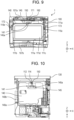
- heating chamber 110 Above heating chamber 110, imaging unit 150 and air blower 160 are provided (see FIGS. 6 and 9 ). Above and on the sides of heating chamber 110, the illuminators (upper illuminator 171, left illuminator 172, and right illuminator 173) are provided to illuminate the inside of the chamber.
- Imaging unit 150 has support frame 151, a camera substrate (not shown), camera 154, a shutter (not shown), and a drive motor (not shown).
- Support frame 151 constituting imaging unit 150 is provided to cover wall surface depression 113 on an upper face of heating chamber 110. Imaging unit 150 is attached to face the inside of heating chamber 110 from the forward side of upper wall 111a of heating chamber 110, in other words, from a side that is closer to front face opening 102 than an approximate center of upper wall 111a is.
- the camera substrate constituting camera 154 has an approximately rectangular flat plate shape, and camera 154 is attached such that the camera substrate is disposed at an approximate center of a surface of the camera substrate that is directed downward when support frame 151 is installed on upper wall 111a of heating chamber 110.
- An imaging surface of camera 154 is formed in an approximately circular shape.
- a charge coupled device (CCD) or a complementary metal-oxide silicon (CMOS) device is used, for example.
- Camera 154 captures an image of the inside of heating chamber 110, on the basis of an instruction from controller 105.
- the camera substrate is attached to support frame 151 in such a manner that an imaging opening, depression bottom opening 114, and wall surface opening 112 are disposed in line in an imaging direction of camera 154, in other words, in a direction of optical axis 157 as shown in FIG. 15 .
- This arrangement enables camera 154 to face the inside of heating chamber 110 and to thus capture an image of the inside of heating chamber 110.
- Imaging unit 150 is attached from the forward side of upper wall 111a of heating chamber 110, in other words, from a side that is closer to front face opening 102 than the center of upper wall 111a is. Further, imaging unit 150 is provided such that an imaging surface of camera 154 is inclined with respect to a horizontal plane such that the imaging direction is directed to an approximately central direction of bottom wall 111e of heating chamber 110. In other words, imaging unit 150 is provided to be inclined such that optical axis 157, which is the imaging direction of camera 154, is directed backward with respect to the vertical direction of heating chamber 110, in other words, such that optical axis 157 is directed away from front face opening 102.
- imaging unit 150 is provided with the imaging direction inclined backward with respect to the vertical direction, it is possible to prevent or reduce an influence, on imaging by imaging unit 150, caused by external light entering through glass window 122 of door 120. Specifically, it is possible to prevent deterioration of imaging accuracy of camera 154 caused by external light having entered through glass window 122 being directly or indirectly superposed with high luminance on an image captured by camera 154.
- Upper illuminator 171 includes illumination substrate 171a, light emitting diodes (LEDs) 171b, and illumination support 171c.
- LEDs light emitting diodes
- Illumination substrate 171a is attached to illumination support 171c.
- Illumination support 171c is attached to upper wall 111a of heating chamber 110.
- FIG. 11 is an exploded perspective view containing the illuminators, heating chamber 110, and top panel 140 of the heating cooking device according to the invention.
- FIG. 12 is an exploded perspective view from below containing heating chamber 110, antenna cover 145, and top panel opening 141 of the heating cooking device according to the invention.
- FIG. 13 is a top view schematic diagram illustrating the configuration and disposition of the illuminators and other components of the heating cooking device.
- FIG. 14 is a schematic diagram of a front view illustrating the configuration and disposition of the illuminators and other components of the heating cooking device.
- illumination opening 115a constituted by a plurality of punched holes at a position behind the center as seen from above.
- Illumination opening 115a is provided with diffuser sheet 170 to cover illumination opening 115a from outside.
- upper illuminator 171 is provided to face the inside of heating chamber 110 through diffuser sheet 170 and illumination opening 115a.
- Upper illuminator 171 is disposed on the rear side with respect to the center of upper wall 111a of heating chamber 110 as seen from above. As seen from above, upper illuminator 171 and imaging unit 150 are disposed at opposite positions with respect to waveguide 107a, which is disposed on upper wall 111a to be inclined with respect to a front-back direction. In other words, upper illuminator 171 and imaging unit 150 are disposed at opposite positions with respect to radiation opening 108a as seen from above (see FIG. 8 ). This arrangement makes it possible to dispose upper illuminator 171 in a small space while avoiding the vicinity of the center seen from above, where various components are disposed.
- stirrer 109a serving as the rotating antenna to stir microwaves.
- Stirrer 109a is provided below upper wall 111a to stir microwaves in heating chamber 110, in other words, stirrer 109a is provided in heating chamber 110.
- top panel opening 141 is provided in top panel 140 to image the inside of heating chamber 110
- antenna cover 145 is provided between stirrer 109a and top panel 140.
- antenna cover 145 is located in an opening of top panel opening 141 as seen from above. Since antenna cover 145 is disposed in this way, it is possible to prevent the user of heating cooking device 1 from touching stirrer 109a.
- Upper illuminator 171 disposed on the upper surface of upper wall 111a is provided above top panel 140 as shown in FIG. 14 , and left illuminator 172 and right illuminator 173 are provided below top panel 140.
- illumination light from upper illuminator 171 disposed on the upper side of heating chamber 110 which is the same side as imaging unit 150 as seen from side, is converted into soft surface illumination light, and is radiated to object 2 to be heated.
- top panel 140 is formed of a semitransparent material, the high-luminance light having reached passes through downward toward heating chamber 110 while spreading horizontally. This arrangement can reduce concentration of luminance and, at the same time, supply an enough amount of light to the upper surface of object 2 to be heated placed in heating chamber 110.
- top panel 140 guides the incident light in the planar direction, in other words, in the horizontal direction. This arrangement makes it possible to illuminate, from top panel 140, a wider area inside the heating chamber 110. As a result, an enough amount of light can be supplied more widely to the upper surface of object 2 to be heated placed in heating chamber 110.
- the illuminator can prevent luminance from increasing locally and, at the same time, the illuminator can illuminate a large area in heating chamber 110, supply a large amount of light, and illuminate the inside of heating chamber 110 from above as a surface light source.
- Imaging unit 150 is provided on the front side of upper wall 111a of heating chamber 110, in other words, the side closer to front face opening 102. Imaging unit 150 is provided such that the imaging direction of camera 154, in other words, optical axis 157 is inclined to be directed backward with respect to the vertical direction of heating chamber 110.
- Imaging unit 150 faces the inside of heating chamber 110 through wall surface opening 112 provided in upper wall 111a and through top panel opening 141 provided in top panel 140.
- imaging unit 150 captures an image with optical axis 157 directed to the inside of heating chamber 110 through wall surface opening 112 formed in upper wall 111a and top panel opening 141 formed in top panel 140.
- the illumination light radiated from upper illuminator 171 is applied to object 2 to be heated through diffuser sheet 170 and top panel 140. That is, the illumination on object 2 to be heated from above is soft surface illumination.
- the illumination on object 2 to be heated from above is soft surface illumination.
- an enough amount of light can be supplied, and an exposure time (or a shutter open time) can be shortened.
- an imaging time by imaging unit 150 can be shortened, operability of a user of heating cooking device 1 can be improved.
- the exposure time can be shortened, it is possible to prevent or reduce blur in an image captured by imaging unit 150 in a case where heating cooking device 1 vibrates. It is possible to supply an enough amount of light and, at the same time, to prevent or reduce occurrence of halation; therefore, in an application for recognizing a captured image as mentioned above, recognition accuracy can be improved.
- Left illuminator 172 and right illuminator 173 radiate light in a right-left direction, in other words, in the horizontal direction. This arrangement makes it possible to supply an enough amount of light also to a lower part, in other words, lower positions in heating chamber 110. Further, since it is possible to prevent or reduce direct incidence of light on imaging unit 150 from left illuminator 172 and right illuminator 173, it is possible to reduce occurrence of halation in an image captured by imaging unit 150.
- a plurality of illuminators specifically, left illuminator 172 and right illuminator 173, are used below top panel 140. This arrangement can prevent or reduce luminance per one illuminator and, at the same time, increase the total amount of light; therefore, the inside of heating chamber 110 can be illuminated more uniformly, and it is possible to reduce occurrence of halation in an image captured by imaging unit 150.
- imaging unit 150 is provided such that optical axis 157 is inclined to be directed backward with respect to the vertical direction of heating chamber 110. Further, below imaging unit 150, top panel 140 is provided from a position of back wall 111d of heating chamber 110 to the vicinity of front face opening 102. This arrangement can prevent or reduce incidence, of external light that enters heating chamber 110 from the outside of heating cooking device 1 through front face opening 102, on camera 154 of imaging unit 150. This arrangement can prevent halation occurring in an image captured by imaging unit 150 due to external light.
- Imaging unit 150 is disposed on the forward side of heating chamber 110 and is inclined to face backward. This arrangement can prevent or reduce incidence of external light on imaging unit 150 while the external light being reflected by the upper surface of object 2 to be heated placed in heating chamber 110, thereby reducing occurrence of halation in an image captured by imaging unit 150.
- imaging unit 150 is provided such that optical axis 157 is inclined to be directed backward with respect to the vertical direction of heating chamber 110.
- Imaging unit 150 faces the inside of heating chamber 110 through wall surface opening 112 provided in upper wall 111a and through top panel opening 141 provided in top panel 140.
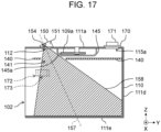
- Field of view 158 shown in FIG. 17 represents an area that is imaged by imaging unit 150. Since top panel opening 141 is provided in top panel 140, imaging unit 150 can image object 2 to be heated placed in heating chamber 110 with a wide field of view 158.
- top panel opening 141 is formed such that a straight line starting from a position of camera 154 of imaging unit 150 and passing through an end part of the forward side of top panel opening 141 intersects a surface of bottom wall 111e of heating chamber 110. That is, top panel opening 141 is formed such that a front end of field of view 158 of camera 154 does not intersect front face opening 102.
- This arrangement can prevent or reduce direct incidence of the external light having entered through front face opening 102, on imaging unit 150. As a result, it is possible to prevent or reduce occurrence of halation in an image captured by imaging unit 150 due to external light.
- the center of top panel opening 141 in the front-back direction is provided on the rear side with respect to the center of imaging unit 150.
- imaging unit 150 is disposed to be inclined toward the back of heating chamber 110, it is possible to prevent or reduce incidence of external light coming through front face opening 102 and, at the same time, to ensure field of view 158 to be wide.
- imaging unit 150 can image object 2 to be heated placed in a large area in heating chamber 110.
- slope 145a is provided on the front side of antenna cover 145, in other words, on a side, of antenna cover 145, toward imaging unit 150.
- Slope 145a is provided on the front side of antenna cover 145 in such a manner that slope 145a is along the inclination of a rear side of field of view 158.
- a rear end of field of view 158 of camera 154 can be such a straight line that starts from the position of camera 154 of imaging unit 150 and passes an end part on the backward side of top panel opening 141.
- field of view 158 is not blocked by antenna cover 145 and is thus ensured to be wide.
- top panel opening 141 is formed such that a straight line starting from the position of camera 154 of imaging unit 150 and passing the end part of the backward side of top panel opening 141 intersects a surface of back wall 111d of heating chamber 110.
- This arrangement enables imaging unit 150 to image a large area of the inside of heating chamber 110.
- Imaging unit 150 can image taller object 2 to be heated placed in heating chamber 110.
- it is possible to prevent or reduce incidence of external light and, at the same time, to image a large area of the inside of heating chamber 110.
- image object 2 to be heated placed at various positions on a bottom surface of heating chamber 110.
- LEDs are used as the light source.
- a light source that emits a large amount of light and has a high luminance, for example, a laser light source or a halogen light source.
- the illuminators include three illuminators, namely, upper illuminator 171, left illuminator 172, and right illuminator 173.
- the number of illuminators may be any number greater than or equal to one.
- the upper illuminator 171 only has to be disposed above top panel 140 to illuminate toward top panel 140.
- flat plate 140a which is the main surface of top panel 140, is constituted by a laminated plate of glass cloth and silicone.
- top panel 140 only has to be made of a semitransparent material that allows light to pass through while softly diffusing the light.
- antenna cover 145 is formed of a polypropylene material.
- antenna cover 145 only has to be made of a flame-retardant material that is microwave permeable, and the usable material is not limited to the polypropylene material.
- Antenna cover 145 is formed approximately circular as seen from above. However, antenna cover 145 only has to have such a shape that covers stirrer 109a and the heater, which are provided to be exposed below upper wall 111a of heating chamber 110.
- This configuration can prevent or reduce halation caused by light entering from outside of the heating cooking device.
- the first illuminator of the heating cooking device may include an LED as a light source. This configuration can improve reliability of the light source and, at the same time, can supply a more amount of light.
- the first illuminator of the heating cooking device may be disposed farther from the front face opening than the center of the heating chamber seen from above is. This configuration can supply the light reflected by the object to be heated, more to the imaging unit.
- the camera and the first illuminator of the heating cooking device may be disposed to face each other with the center of the heating chamber interposed between the camera and the first illuminator as seen from above.
- This configuration can supply the light reflected by the object to be heated, more to the imaging unit.
- a second illuminator and a third illuminator each illuminating the inside of the heating chamber. This configuration can prevent halation and, at the same time, can supply a larger amount of light to the inside of the chamber.
- each of the second illuminator and the third illuminator of the heating cooking device may be disposed one of the right and left side walls, of the heating chamber, facing each other at a position that is closer to the front face opening than an approximate center of the heating chamber seen from side is. This configuration can prevent halation and, at the same time, can supply an enough amount of light also to lower positions. high accuracy.
- the present disclosure can be applied to a heating cooking device the inside of whose chamber is imaged by an imaging unit.
Landscapes
- Engineering & Computer Science (AREA)
- Chemical & Material Sciences (AREA)
- Combustion & Propulsion (AREA)
- Mechanical Engineering (AREA)
- General Engineering & Computer Science (AREA)
- Physics & Mathematics (AREA)
- Electromagnetism (AREA)
- Electric Ovens (AREA)
- Electric Stoves And Ranges (AREA)
- Compression-Type Refrigeration Machines With Reversible Cycles (AREA)
- Resistance Heating (AREA)
Claims (7)
- Erwärmungskochvorrichtung (1), die umfasst:eine Erwärmungskammer (110) mit einer Vorderseitenöffnung (102) an einer Vorderseite der Erwärmungskammer (110), einer oberen Wand (111a), die an einem oberen Teil der Erwärmungskammer (110) angeordnet ist, einer linken Seitenwand (111b), die an einem linken Teil der Erwärmungskammer (110) angeordnet ist, eine rechte Seitenwand (111c), die an einem rechten Seitenteil der Erwärmungskammer (110) angeordnet ist, eine Rückwand (111d), die an einem hinteren Teil der Erwärmungskammer (110) angeordnet ist, und eine Bodenwand (111e), die an einem unteren Teil der Erwärmungskammer (110) angeordnet ist;eine Erwärmungseinrichtung (106a, 106b), die so konfiguriert ist, dass sie einen zu erwärmenden Gegenstand (2) erwärmt, der in der Erwärmungskammer (110) gelagert ist;eine Kamera (154), die eine optische Achse (157) hat und an der oberen Wand (111a) der Erwärmungskammer (110) so angeordnet ist, dass sie ins Innere der Erwärmungskammer (110) weist; undeiner ersten Beleuchtung (171), die auf einer Oberseite der oberen Wand (111a) angeordnet und so konfiguriert ist, dass sie Licht in das Innere der Erwärmungskammer (110) strahlt;dadurch gekennzeichnet, dass:
die Erwärmungs-Kochvorrichtung (1) ferner umfasst:eine obere Platte (140), die unterhalb der oberen Wand (111a) der Erwärmungskammer (110) angeordnet ist, wobei die obere Platte (140) Folgendes umfasst: Ein halbtransparentes Element, das so konfiguriert ist, dass es das Licht der ersten Beleuchtung (171) streut, um es nach unten zu leuchten, wobei die obere Platte (140) eine obere Plattenöffnung (141) aufweist, die als Öffnung dient, durch die die Kamera (154) das Innere der Erwärmungskammer (110) abbildet,wobei die obere Platte (140) eine flache Platte (140a) ist, die parallel zur oberen Wand (111a) mit einem Zwischenraum zwischen der oberen Platte (140) und der oberen Wand (111a) vorgesehen ist,wobei die Kamera (154) bei Betrachtung von oben näher an der Vorderseitenöffnung (102) angeordnet ist als eine Mitte der oberen Wand (111a), unddie optische Achse (157) in Bezug auf eine vertikale Richtung zu einer Rückseite der Erwärmungskammer (110) hin geneigt ist. - Erwärmungskochvorrichtung (1) nach Anspruch 1, wobei die erste Beleuchtung (171) eine Leuchtdiode als Lichtquelle umfasst.
- Erwärmungskochvorrichtung (1) nach Anspruch 1, wobei die erste Beleuchtung (171) von oben betrachtet weiter von der Vorderseitenöffnung (102) entfernt angeordnet ist als eine Mitte der oberen Wand (111a).
- Erwärmungskochvorrichtung (1) nach Anspruch 1, wobei die Kamera (154) und die erste Beleuchtung (171) so angeordnet sind, dass sie einander zugewandt sind, wobei eine Mitte der oberen Wand (111a) zwischen der Kamera (154) und der ersten Beleuchtung (171) angeordnet ist.
- Erwärmungskochvorrichtung (1) nach einem der Ansprüche 1 bis 3, die ferner umfasst:
eine zweite Beleuchtung (172) und eine dritte Beleuchtung (173), die unter der oberen Platte (140) angeordnet sind, wobei die zweite Beleuchtung (172) und die dritte Beleuchtung (173) jeweils das Innere der Erwärmungskammer (110) beleuchten. - Erwärmungskochvorrichtung (1) nach Anspruch 5, wobeidie zweite Beleuchtung (172) an einer Position an der linken Seitenwand (111b) der Erwärmungskammer angeordnet ist, wobei die Position der zweiten Beleuchtung (172) von oben gesehen näher an der Vorderseitenöffnung (102) liegt als an einer Mitte der linken Seitenwand (111b), unddie dritte Beleuchtung (173) an einer Position an der rechten Seitenwand (111c) der Erwärmungskammer (110) angeordnet ist, wobei die Position der dritten Beleuchtung (173) von oben gesehen näher an der Vorderseitenöffnung (102) liegt als an einer Mitte der rechten Seitenwand (111c), wobei die rechte Seitenwand (111c) der linken Seitenwand (111b) zugewandt ist.
- Erwärmungskochvorrichtung nach einem der Ansprüche 1 bis 6, die ferner umfasst:eine Beleuchtungsöffnung (115a), die in der oberen Wand (111a) der Erwärmungskammer (110) geöffnet ist,wobei die obere Platte (140) von oben gesehen eine größere Fläche aufweist als die Beleuchtungsöffnung (115a), so geformt ist, dass sie von oben gesehen nicht mit der Kamera (154) überlappt, und aus einem halbtransparenten Material besteht, um es zu gestatten, dass Lichtabstrahlung von der ersten Beleuchtung (171) nach unten hindurchgeht und das Licht dabei gestreut wird.
Applications Claiming Priority (2)
| Application Number | Priority Date | Filing Date | Title |
|---|---|---|---|
| JP2018085909A JP7108820B2 (ja) | 2018-04-27 | 2018-04-27 | 加熱調理器 |
| PCT/JP2019/016914 WO2019208458A1 (ja) | 2018-04-27 | 2019-04-22 | 加熱調理器 |
Publications (3)
| Publication Number | Publication Date |
|---|---|
| EP3786526A1 EP3786526A1 (de) | 2021-03-03 |
| EP3786526A4 EP3786526A4 (de) | 2021-06-23 |
| EP3786526B1 true EP3786526B1 (de) | 2023-12-20 |
Family
ID=68295327
Family Applications (1)
| Application Number | Title | Priority Date | Filing Date |
|---|---|---|---|
| EP19791561.4A Active EP3786526B1 (de) | 2018-04-27 | 2019-04-22 | Kochvorrichtung |
Country Status (6)
| Country | Link |
|---|---|
| US (1) | US20210095862A1 (de) |
| EP (1) | EP3786526B1 (de) |
| JP (1) | JP7108820B2 (de) |
| CN (1) | CN112005056B (de) |
| TW (1) | TWI779187B (de) |
| WO (1) | WO2019208458A1 (de) |
Families Citing this family (5)
| Publication number | Priority date | Publication date | Assignee | Title |
|---|---|---|---|---|
| KR102920403B1 (ko) * | 2020-10-15 | 2026-01-30 | 엘지전자 주식회사 | 조리 장치 |
| US11649970B2 (en) | 2020-11-20 | 2023-05-16 | Haier Us Appliance Solutions, Inc. | Lighting assembly for an over-the-range appliance |
| WO2022249752A1 (ja) * | 2021-05-26 | 2022-12-01 | シャープ株式会社 | 撮像装置 |
| JP7737285B2 (ja) * | 2021-10-19 | 2025-09-10 | シャープ株式会社 | 加熱調理器 |
| KR20250031618A (ko) * | 2023-08-29 | 2025-03-07 | 엘지전자 주식회사 | 조리기기 |
Family Cites Families (17)
| Publication number | Priority date | Publication date | Assignee | Title |
|---|---|---|---|---|
| JPS5944793A (ja) | 1982-09-08 | 1984-03-13 | 株式会社東芝 | 調理器 |
| US4507529A (en) * | 1983-06-29 | 1985-03-26 | General Electric Company | Food emission sensing |
| KR100329543B1 (ko) * | 1998-07-29 | 2002-08-21 | 엘지전자주식회사 | 전자레인지의할로겐램프냉각구조 |
| JP4558112B2 (ja) * | 1998-10-13 | 2010-10-06 | 山形カシオ株式会社 | 部品搭載装置用の照明装置とその照明装置を備える部品搭載装置 |
| JP2003056852A (ja) * | 2001-08-09 | 2003-02-26 | Hitachi Hometec Ltd | 加熱調理器 |
| CN1888565A (zh) * | 2005-06-30 | 2007-01-03 | 乐金电子(天津)电器有限公司 | 微波炉的照明灯安装结构 |
| DE102009002775A1 (de) * | 2009-04-30 | 2010-11-04 | BSH Bosch und Siemens Hausgeräte GmbH | Lampe für Hausgerät sowie Hausgerät, insbesondere zum Zubereiten von Lebensmitteln, mit einer Lampe |
| KR101044207B1 (ko) * | 2009-06-15 | 2011-06-29 | 엘지전자 주식회사 | 조리기기 및 그 제어방법 |
| US20120170247A1 (en) * | 2011-01-05 | 2012-07-05 | General Electric Company | Method of using light-emitting diode (led) lighting to illuminate the interior of microwave ovens |
| JP5747162B2 (ja) * | 2011-07-26 | 2015-07-08 | パナソニックIpマネジメント株式会社 | 高周波調理器 |
| US9454265B2 (en) * | 2013-09-23 | 2016-09-27 | Qualcomm Incorporated | Integration of a light collection light-guide with a field sequential color display |
| JP6579301B2 (ja) * | 2014-10-10 | 2019-09-25 | パナソニックIpマネジメント株式会社 | 加熱調理器 |
| CN205026746U (zh) * | 2015-08-22 | 2016-02-10 | 天津有序环境科技发展有限公司 | 视频监控遥控微波炉 |
| US10716174B2 (en) | 2015-11-27 | 2020-07-14 | Panasonic Intellectual Property Management Co., Ltd. | Heating cooker, method for controlling heating cooker, and heating cooking system |
| CN108885008A (zh) | 2016-03-29 | 2018-11-23 | 松下知识产权经营株式会社 | 加热烹调器 |
| US10591218B2 (en) * | 2017-10-27 | 2020-03-17 | Whirlpool Corporation | Oven having an imaging device |
| CN107842885A (zh) * | 2017-11-07 | 2018-03-27 | 深圳市得城网络科技有限公司 | 可视智能微波炉 |
-
2018
- 2018-04-27 JP JP2018085909A patent/JP7108820B2/ja active Active
-
2019
- 2019-04-17 TW TW108113409A patent/TWI779187B/zh active
- 2019-04-22 EP EP19791561.4A patent/EP3786526B1/de active Active
- 2019-04-22 CN CN201980027484.XA patent/CN112005056B/zh active Active
- 2019-04-22 WO PCT/JP2019/016914 patent/WO2019208458A1/ja not_active Ceased
- 2019-04-22 US US17/044,830 patent/US20210095862A1/en not_active Abandoned
Also Published As
| Publication number | Publication date |
|---|---|
| CN112005056B (zh) | 2023-02-28 |
| CN112005056A (zh) | 2020-11-27 |
| JP2019190770A (ja) | 2019-10-31 |
| JP7108820B2 (ja) | 2022-07-29 |
| US20210095862A1 (en) | 2021-04-01 |
| EP3786526A4 (de) | 2021-06-23 |
| EP3786526A1 (de) | 2021-03-03 |
| TWI779187B (zh) | 2022-10-01 |
| TW201945669A (zh) | 2019-12-01 |
| WO2019208458A1 (ja) | 2019-10-31 |
Similar Documents
| Publication | Publication Date | Title |
|---|---|---|
| EP3786526B1 (de) | Kochvorrichtung | |
| JP7126046B2 (ja) | 加熱調理器 | |
| EP3786527B1 (de) | Kochvorrichtung mit kamera | |
| CN106662332B (zh) | 加热烹调器 | |
| JP7727928B2 (ja) | 加熱調理器 | |
| JP7489588B2 (ja) | 加熱調理器 | |
| JP7737285B2 (ja) | 加熱調理器 | |
| JP2026056812A (ja) | 加熱調理器 | |
| JP2026056813A (ja) | 加熱調理器 |
Legal Events
| Date | Code | Title | Description |
|---|---|---|---|
| STAA | Information on the status of an ep patent application or granted ep patent |
Free format text: STATUS: THE INTERNATIONAL PUBLICATION HAS BEEN MADE |
|
| PUAI | Public reference made under article 153(3) epc to a published international application that has entered the european phase |
Free format text: ORIGINAL CODE: 0009012 |
|
| STAA | Information on the status of an ep patent application or granted ep patent |
Free format text: STATUS: REQUEST FOR EXAMINATION WAS MADE |
|
| 17P | Request for examination filed |
Effective date: 20201021 |
|
| AK | Designated contracting states |
Kind code of ref document: A1 Designated state(s): AL AT BE BG CH CY CZ DE DK EE ES FI FR GB GR HR HU IE IS IT LI LT LU LV MC MK MT NL NO PL PT RO RS SE SI SK SM TR |
|
| AX | Request for extension of the european patent |
Extension state: BA ME |
|
| A4 | Supplementary search report drawn up and despatched |
Effective date: 20210525 |
|
| RIC1 | Information provided on ipc code assigned before grant |
Ipc: F24C 7/08 20060101AFI20210518BHEP Ipc: F24C 15/00 20060101ALI20210518BHEP Ipc: H05B 6/64 20060101ALI20210518BHEP Ipc: F24C 7/02 20060101ALI20210518BHEP |
|
| DAV | Request for validation of the european patent (deleted) | ||
| DAX | Request for extension of the european patent (deleted) | ||
| REG | Reference to a national code |
Ref legal event code: R079 Ipc: F24C0007080000 Ref country code: DE Ref legal event code: R079 Ref document number: 602019043673 Country of ref document: DE Free format text: PREVIOUS MAIN CLASS: F24C0007020000 Ipc: F24C0007080000 |
|
| GRAP | Despatch of communication of intention to grant a patent |
Free format text: ORIGINAL CODE: EPIDOSNIGR1 |
|
| STAA | Information on the status of an ep patent application or granted ep patent |
Free format text: STATUS: GRANT OF PATENT IS INTENDED |
|
| RIC1 | Information provided on ipc code assigned before grant |
Ipc: H05B 6/64 20060101ALI20230711BHEP Ipc: F24C 7/04 20210101ALI20230711BHEP Ipc: F24C 15/00 20060101ALI20230711BHEP Ipc: F24C 7/08 20060101AFI20230711BHEP |
|
| INTG | Intention to grant announced |
Effective date: 20230731 |
|
| GRAS | Grant fee paid |
Free format text: ORIGINAL CODE: EPIDOSNIGR3 |
|
| GRAA | (expected) grant |
Free format text: ORIGINAL CODE: 0009210 |
|
| STAA | Information on the status of an ep patent application or granted ep patent |
Free format text: STATUS: THE PATENT HAS BEEN GRANTED |
|
| AK | Designated contracting states |
Kind code of ref document: B1 Designated state(s): AL AT BE BG CH CY CZ DE DK EE ES FI FR GB GR HR HU IE IS IT LI LT LU LV MC MK MT NL NO PL PT RO RS SE SI SK SM TR |
|
| REG | Reference to a national code |
Ref country code: GB Ref legal event code: FG4D |
|
| RIN1 | Information on inventor provided before grant (corrected) |
Inventor name: SHIMIZU, TAKUZO Inventor name: HAYASHI, HIROKI Inventor name: NAKASHIMA, TAKESHI |
|
| REG | Reference to a national code |
Ref country code: CH Ref legal event code: EP |
|
| REG | Reference to a national code |
Ref country code: DE Ref legal event code: R096 Ref document number: 602019043673 Country of ref document: DE |
|
| REG | Reference to a national code |
Ref country code: IE Ref legal event code: FG4D |
|
| PG25 | Lapsed in a contracting state [announced via postgrant information from national office to epo] |
Ref country code: GR Free format text: LAPSE BECAUSE OF FAILURE TO SUBMIT A TRANSLATION OF THE DESCRIPTION OR TO PAY THE FEE WITHIN THE PRESCRIBED TIME-LIMIT Effective date: 20240321 |
|
| REG | Reference to a national code |
Ref country code: LT Ref legal event code: MG9D |
|
| PG25 | Lapsed in a contracting state [announced via postgrant information from national office to epo] |
Ref country code: LT Free format text: LAPSE BECAUSE OF FAILURE TO SUBMIT A TRANSLATION OF THE DESCRIPTION OR TO PAY THE FEE WITHIN THE PRESCRIBED TIME-LIMIT Effective date: 20231220 |
|
| REG | Reference to a national code |
Ref country code: NL Ref legal event code: MP Effective date: 20231220 |
|
| PG25 | Lapsed in a contracting state [announced via postgrant information from national office to epo] |
Ref country code: ES Free format text: LAPSE BECAUSE OF FAILURE TO SUBMIT A TRANSLATION OF THE DESCRIPTION OR TO PAY THE FEE WITHIN THE PRESCRIBED TIME-LIMIT Effective date: 20231220 |
|
| PG25 | Lapsed in a contracting state [announced via postgrant information from national office to epo] |
Ref country code: LT Free format text: LAPSE BECAUSE OF FAILURE TO SUBMIT A TRANSLATION OF THE DESCRIPTION OR TO PAY THE FEE WITHIN THE PRESCRIBED TIME-LIMIT Effective date: 20231220 Ref country code: GR Free format text: LAPSE BECAUSE OF FAILURE TO SUBMIT A TRANSLATION OF THE DESCRIPTION OR TO PAY THE FEE WITHIN THE PRESCRIBED TIME-LIMIT Effective date: 20240321 Ref country code: FI Free format text: LAPSE BECAUSE OF FAILURE TO SUBMIT A TRANSLATION OF THE DESCRIPTION OR TO PAY THE FEE WITHIN THE PRESCRIBED TIME-LIMIT Effective date: 20231220 Ref country code: ES Free format text: LAPSE BECAUSE OF FAILURE TO SUBMIT A TRANSLATION OF THE DESCRIPTION OR TO PAY THE FEE WITHIN THE PRESCRIBED TIME-LIMIT Effective date: 20231220 Ref country code: BG Free format text: LAPSE BECAUSE OF FAILURE TO SUBMIT A TRANSLATION OF THE DESCRIPTION OR TO PAY THE FEE WITHIN THE PRESCRIBED TIME-LIMIT Effective date: 20240320 |
|
| REG | Reference to a national code |
Ref country code: AT Ref legal event code: MK05 Ref document number: 1642760 Country of ref document: AT Kind code of ref document: T Effective date: 20231220 |
|
| PG25 | Lapsed in a contracting state [announced via postgrant information from national office to epo] |
Ref country code: NL Free format text: LAPSE BECAUSE OF FAILURE TO SUBMIT A TRANSLATION OF THE DESCRIPTION OR TO PAY THE FEE WITHIN THE PRESCRIBED TIME-LIMIT Effective date: 20231220 |
|
| PG25 | Lapsed in a contracting state [announced via postgrant information from national office to epo] |
Ref country code: SE Free format text: LAPSE BECAUSE OF FAILURE TO SUBMIT A TRANSLATION OF THE DESCRIPTION OR TO PAY THE FEE WITHIN THE PRESCRIBED TIME-LIMIT Effective date: 20231220 Ref country code: RS Free format text: LAPSE BECAUSE OF FAILURE TO SUBMIT A TRANSLATION OF THE DESCRIPTION OR TO PAY THE FEE WITHIN THE PRESCRIBED TIME-LIMIT Effective date: 20231220 Ref country code: NO Free format text: LAPSE BECAUSE OF FAILURE TO SUBMIT A TRANSLATION OF THE DESCRIPTION OR TO PAY THE FEE WITHIN THE PRESCRIBED TIME-LIMIT Effective date: 20240320 Ref country code: NL Free format text: LAPSE BECAUSE OF FAILURE TO SUBMIT A TRANSLATION OF THE DESCRIPTION OR TO PAY THE FEE WITHIN THE PRESCRIBED TIME-LIMIT Effective date: 20231220 Ref country code: LV Free format text: LAPSE BECAUSE OF FAILURE TO SUBMIT A TRANSLATION OF THE DESCRIPTION OR TO PAY THE FEE WITHIN THE PRESCRIBED TIME-LIMIT Effective date: 20231220 Ref country code: HR Free format text: LAPSE BECAUSE OF FAILURE TO SUBMIT A TRANSLATION OF THE DESCRIPTION OR TO PAY THE FEE WITHIN THE PRESCRIBED TIME-LIMIT Effective date: 20231220 |
|
| PG25 | Lapsed in a contracting state [announced via postgrant information from national office to epo] |
Ref country code: IS Free format text: LAPSE BECAUSE OF FAILURE TO SUBMIT A TRANSLATION OF THE DESCRIPTION OR TO PAY THE FEE WITHIN THE PRESCRIBED TIME-LIMIT Effective date: 20240420 |
|
| PG25 | Lapsed in a contracting state [announced via postgrant information from national office to epo] |
Ref country code: CZ Free format text: LAPSE BECAUSE OF FAILURE TO SUBMIT A TRANSLATION OF THE DESCRIPTION OR TO PAY THE FEE WITHIN THE PRESCRIBED TIME-LIMIT Effective date: 20231220 Ref country code: AT Free format text: LAPSE BECAUSE OF FAILURE TO SUBMIT A TRANSLATION OF THE DESCRIPTION OR TO PAY THE FEE WITHIN THE PRESCRIBED TIME-LIMIT Effective date: 20231220 |
|
| PG25 | Lapsed in a contracting state [announced via postgrant information from national office to epo] |
Ref country code: SK Free format text: LAPSE BECAUSE OF FAILURE TO SUBMIT A TRANSLATION OF THE DESCRIPTION OR TO PAY THE FEE WITHIN THE PRESCRIBED TIME-LIMIT Effective date: 20231220 |
|
| PG25 | Lapsed in a contracting state [announced via postgrant information from national office to epo] |
Ref country code: SM Free format text: LAPSE BECAUSE OF FAILURE TO SUBMIT A TRANSLATION OF THE DESCRIPTION OR TO PAY THE FEE WITHIN THE PRESCRIBED TIME-LIMIT Effective date: 20231220 Ref country code: SK Free format text: LAPSE BECAUSE OF FAILURE TO SUBMIT A TRANSLATION OF THE DESCRIPTION OR TO PAY THE FEE WITHIN THE PRESCRIBED TIME-LIMIT Effective date: 20231220 Ref country code: RO Free format text: LAPSE BECAUSE OF FAILURE TO SUBMIT A TRANSLATION OF THE DESCRIPTION OR TO PAY THE FEE WITHIN THE PRESCRIBED TIME-LIMIT Effective date: 20231220 Ref country code: IT Free format text: LAPSE BECAUSE OF FAILURE TO SUBMIT A TRANSLATION OF THE DESCRIPTION OR TO PAY THE FEE WITHIN THE PRESCRIBED TIME-LIMIT Effective date: 20231220 Ref country code: IS Free format text: LAPSE BECAUSE OF FAILURE TO SUBMIT A TRANSLATION OF THE DESCRIPTION OR TO PAY THE FEE WITHIN THE PRESCRIBED TIME-LIMIT Effective date: 20240420 Ref country code: EE Free format text: LAPSE BECAUSE OF FAILURE TO SUBMIT A TRANSLATION OF THE DESCRIPTION OR TO PAY THE FEE WITHIN THE PRESCRIBED TIME-LIMIT Effective date: 20231220 Ref country code: CZ Free format text: LAPSE BECAUSE OF FAILURE TO SUBMIT A TRANSLATION OF THE DESCRIPTION OR TO PAY THE FEE WITHIN THE PRESCRIBED TIME-LIMIT Effective date: 20231220 Ref country code: AT Free format text: LAPSE BECAUSE OF FAILURE TO SUBMIT A TRANSLATION OF THE DESCRIPTION OR TO PAY THE FEE WITHIN THE PRESCRIBED TIME-LIMIT Effective date: 20231220 |
|
| PG25 | Lapsed in a contracting state [announced via postgrant information from national office to epo] |
Ref country code: PT Free format text: LAPSE BECAUSE OF FAILURE TO SUBMIT A TRANSLATION OF THE DESCRIPTION OR TO PAY THE FEE WITHIN THE PRESCRIBED TIME-LIMIT Effective date: 20240422 Ref country code: PL Free format text: LAPSE BECAUSE OF FAILURE TO SUBMIT A TRANSLATION OF THE DESCRIPTION OR TO PAY THE FEE WITHIN THE PRESCRIBED TIME-LIMIT Effective date: 20231220 |
|
| PG25 | Lapsed in a contracting state [announced via postgrant information from national office to epo] |
Ref country code: PT Free format text: LAPSE BECAUSE OF FAILURE TO SUBMIT A TRANSLATION OF THE DESCRIPTION OR TO PAY THE FEE WITHIN THE PRESCRIBED TIME-LIMIT Effective date: 20240422 Ref country code: PL Free format text: LAPSE BECAUSE OF FAILURE TO SUBMIT A TRANSLATION OF THE DESCRIPTION OR TO PAY THE FEE WITHIN THE PRESCRIBED TIME-LIMIT Effective date: 20231220 |
|
| REG | Reference to a national code |
Ref country code: DE Ref legal event code: R097 Ref document number: 602019043673 Country of ref document: DE |
|
| PG25 | Lapsed in a contracting state [announced via postgrant information from national office to epo] |
Ref country code: DK Free format text: LAPSE BECAUSE OF FAILURE TO SUBMIT A TRANSLATION OF THE DESCRIPTION OR TO PAY THE FEE WITHIN THE PRESCRIBED TIME-LIMIT Effective date: 20231220 |
|
| PLBE | No opposition filed within time limit |
Free format text: ORIGINAL CODE: 0009261 |
|
| STAA | Information on the status of an ep patent application or granted ep patent |
Free format text: STATUS: NO OPPOSITION FILED WITHIN TIME LIMIT |
|
| PG25 | Lapsed in a contracting state [announced via postgrant information from national office to epo] |
Ref country code: SI Free format text: LAPSE BECAUSE OF FAILURE TO SUBMIT A TRANSLATION OF THE DESCRIPTION OR TO PAY THE FEE WITHIN THE PRESCRIBED TIME-LIMIT Effective date: 20231220 |
|
| PG25 | Lapsed in a contracting state [announced via postgrant information from national office to epo] |
Ref country code: SI Free format text: LAPSE BECAUSE OF FAILURE TO SUBMIT A TRANSLATION OF THE DESCRIPTION OR TO PAY THE FEE WITHIN THE PRESCRIBED TIME-LIMIT Effective date: 20231220 Ref country code: DK Free format text: LAPSE BECAUSE OF FAILURE TO SUBMIT A TRANSLATION OF THE DESCRIPTION OR TO PAY THE FEE WITHIN THE PRESCRIBED TIME-LIMIT Effective date: 20231220 |
|
| PG25 | Lapsed in a contracting state [announced via postgrant information from national office to epo] |
Ref country code: MC Free format text: LAPSE BECAUSE OF FAILURE TO SUBMIT A TRANSLATION OF THE DESCRIPTION OR TO PAY THE FEE WITHIN THE PRESCRIBED TIME-LIMIT Effective date: 20231220 |
|
| 26N | No opposition filed |
Effective date: 20240923 |
|
| PG25 | Lapsed in a contracting state [announced via postgrant information from national office to epo] |
Ref country code: MC Free format text: LAPSE BECAUSE OF FAILURE TO SUBMIT A TRANSLATION OF THE DESCRIPTION OR TO PAY THE FEE WITHIN THE PRESCRIBED TIME-LIMIT Effective date: 20231220 |
|
| REG | Reference to a national code |
Ref country code: CH Ref legal event code: PL |
|
| PG25 | Lapsed in a contracting state [announced via postgrant information from national office to epo] |
Ref country code: LU Free format text: LAPSE BECAUSE OF NON-PAYMENT OF DUE FEES Effective date: 20240422 |
|
| GBPC | Gb: european patent ceased through non-payment of renewal fee |
Effective date: 20240422 |
|
| REG | Reference to a national code |
Ref country code: BE Ref legal event code: MM Effective date: 20240430 |
|
| PG25 | Lapsed in a contracting state [announced via postgrant information from national office to epo] |
Ref country code: LU Free format text: LAPSE BECAUSE OF NON-PAYMENT OF DUE FEES Effective date: 20240422 |
|
| PG25 | Lapsed in a contracting state [announced via postgrant information from national office to epo] |
Ref country code: BE Free format text: LAPSE BECAUSE OF NON-PAYMENT OF DUE FEES Effective date: 20240430 |
|
| PG25 | Lapsed in a contracting state [announced via postgrant information from national office to epo] |
Ref country code: GB Free format text: LAPSE BECAUSE OF NON-PAYMENT OF DUE FEES Effective date: 20240422 |
|
| PG25 | Lapsed in a contracting state [announced via postgrant information from national office to epo] |
Ref country code: FR Free format text: LAPSE BECAUSE OF NON-PAYMENT OF DUE FEES Effective date: 20240430 |
|
| PG25 | Lapsed in a contracting state [announced via postgrant information from national office to epo] |
Ref country code: GB Free format text: LAPSE BECAUSE OF NON-PAYMENT OF DUE FEES Effective date: 20240422 Ref country code: FR Free format text: LAPSE BECAUSE OF NON-PAYMENT OF DUE FEES Effective date: 20240430 Ref country code: BE Free format text: LAPSE BECAUSE OF NON-PAYMENT OF DUE FEES Effective date: 20240430 Ref country code: CH Free format text: LAPSE BECAUSE OF NON-PAYMENT OF DUE FEES Effective date: 20240430 |
|
| PG25 | Lapsed in a contracting state [announced via postgrant information from national office to epo] |
Ref country code: IE Free format text: LAPSE BECAUSE OF NON-PAYMENT OF DUE FEES Effective date: 20240422 |
|
| PGFP | Annual fee paid to national office [announced via postgrant information from national office to epo] |
Ref country code: DE Payment date: 20250422 Year of fee payment: 7 |
|
| PG25 | Lapsed in a contracting state [announced via postgrant information from national office to epo] |
Ref country code: CY Free format text: LAPSE BECAUSE OF FAILURE TO SUBMIT A TRANSLATION OF THE DESCRIPTION OR TO PAY THE FEE WITHIN THE PRESCRIBED TIME-LIMIT; INVALID AB INITIO Effective date: 20190422 |
|
| PG25 | Lapsed in a contracting state [announced via postgrant information from national office to epo] |
Ref country code: HU Free format text: LAPSE BECAUSE OF FAILURE TO SUBMIT A TRANSLATION OF THE DESCRIPTION OR TO PAY THE FEE WITHIN THE PRESCRIBED TIME-LIMIT; INVALID AB INITIO Effective date: 20190422 |