EP3786559B1 - Heat exchanger assembly - Google Patents
Heat exchanger assembly Download PDFInfo
- Publication number
- EP3786559B1 EP3786559B1 EP19315107.3A EP19315107A EP3786559B1 EP 3786559 B1 EP3786559 B1 EP 3786559B1 EP 19315107 A EP19315107 A EP 19315107A EP 3786559 B1 EP3786559 B1 EP 3786559B1
- Authority
- EP
- European Patent Office
- Prior art keywords
- heat exchanger
- fan
- assembly
- casing
- sloped wall
- Prior art date
- Legal status (The legal status is an assumption and is not a legal conclusion. Google has not performed a legal analysis and makes no representation as to the accuracy of the status listed.)
- Active
Links
Images







Classifications
-
- F—MECHANICAL ENGINEERING; LIGHTING; HEATING; WEAPONS; BLASTING
- F28—HEAT EXCHANGE IN GENERAL
- F28D—HEAT-EXCHANGE APPARATUS, NOT PROVIDED FOR IN ANOTHER SUBCLASS, IN WHICH THE HEAT-EXCHANGE MEDIA DO NOT COME INTO DIRECT CONTACT
- F28D1/00—Heat-exchange apparatus having stationary conduit assemblies for one heat-exchange medium only, the media being in contact with different sides of the conduit wall, in which the other heat-exchange medium is a large body of fluid, e.g. domestic or motor car radiators
- F28D1/02—Heat-exchange apparatus having stationary conduit assemblies for one heat-exchange medium only, the media being in contact with different sides of the conduit wall, in which the other heat-exchange medium is a large body of fluid, e.g. domestic or motor car radiators with heat-exchange conduits immersed in the body of fluid
- F28D1/04—Heat-exchange apparatus having stationary conduit assemblies for one heat-exchange medium only, the media being in contact with different sides of the conduit wall, in which the other heat-exchange medium is a large body of fluid, e.g. domestic or motor car radiators with heat-exchange conduits immersed in the body of fluid with tubular conduits
- F28D1/047—Heat-exchange apparatus having stationary conduit assemblies for one heat-exchange medium only, the media being in contact with different sides of the conduit wall, in which the other heat-exchange medium is a large body of fluid, e.g. domestic or motor car radiators with heat-exchange conduits immersed in the body of fluid with tubular conduits the conduits being bent, e.g. in a serpentine or zig-zag
- F28D1/0477—Heat-exchange apparatus having stationary conduit assemblies for one heat-exchange medium only, the media being in contact with different sides of the conduit wall, in which the other heat-exchange medium is a large body of fluid, e.g. domestic or motor car radiators with heat-exchange conduits immersed in the body of fluid with tubular conduits the conduits being bent, e.g. in a serpentine or zig-zag the conduits being bent in a serpentine or zig-zag
-
- F—MECHANICAL ENGINEERING; LIGHTING; HEATING; WEAPONS; BLASTING
- F04—POSITIVE - DISPLACEMENT MACHINES FOR LIQUIDS; PUMPS FOR LIQUIDS OR ELASTIC FLUIDS
- F04D—NON-POSITIVE-DISPLACEMENT PUMPS
- F04D25/00—Pumping installations or systems
- F04D25/16—Combinations of two or more pumps ; Producing two or more separate gas flows
- F04D25/166—Combinations of two or more pumps ; Producing two or more separate gas flows using fans
-
- F—MECHANICAL ENGINEERING; LIGHTING; HEATING; WEAPONS; BLASTING
- F28—HEAT EXCHANGE IN GENERAL
- F28D—HEAT-EXCHANGE APPARATUS, NOT PROVIDED FOR IN ANOTHER SUBCLASS, IN WHICH THE HEAT-EXCHANGE MEDIA DO NOT COME INTO DIRECT CONTACT
- F28D1/00—Heat-exchange apparatus having stationary conduit assemblies for one heat-exchange medium only, the media being in contact with different sides of the conduit wall, in which the other heat-exchange medium is a large body of fluid, e.g. domestic or motor car radiators
- F28D1/02—Heat-exchange apparatus having stationary conduit assemblies for one heat-exchange medium only, the media being in contact with different sides of the conduit wall, in which the other heat-exchange medium is a large body of fluid, e.g. domestic or motor car radiators with heat-exchange conduits immersed in the body of fluid
- F28D1/0233—Heat-exchange apparatus having stationary conduit assemblies for one heat-exchange medium only, the media being in contact with different sides of the conduit wall, in which the other heat-exchange medium is a large body of fluid, e.g. domestic or motor car radiators with heat-exchange conduits immersed in the body of fluid with air flow channels
- F28D1/024—Heat-exchange apparatus having stationary conduit assemblies for one heat-exchange medium only, the media being in contact with different sides of the conduit wall, in which the other heat-exchange medium is a large body of fluid, e.g. domestic or motor car radiators with heat-exchange conduits immersed in the body of fluid with air flow channels with an air driving element
-
- F—MECHANICAL ENGINEERING; LIGHTING; HEATING; WEAPONS; BLASTING
- F04—POSITIVE - DISPLACEMENT MACHINES FOR LIQUIDS; PUMPS FOR LIQUIDS OR ELASTIC FLUIDS
- F04D—NON-POSITIVE-DISPLACEMENT PUMPS
- F04D25/00—Pumping installations or systems
- F04D25/02—Units comprising pumps and their driving means
- F04D25/06—Units comprising pumps and their driving means the pump being electrically driven
- F04D25/0606—Units comprising pumps and their driving means the pump being electrically driven the electric motor being specially adapted for integration in the pump
-
- F—MECHANICAL ENGINEERING; LIGHTING; HEATING; WEAPONS; BLASTING
- F04—POSITIVE - DISPLACEMENT MACHINES FOR LIQUIDS; PUMPS FOR LIQUIDS OR ELASTIC FLUIDS
- F04D—NON-POSITIVE-DISPLACEMENT PUMPS
- F04D29/00—Details, component parts, or accessories
- F04D29/26—Rotors specially for elastic fluids
- F04D29/32—Rotors specially for elastic fluids for axial flow pumps
- F04D29/325—Rotors specially for elastic fluids for axial flow pumps for axial flow fans
-
- F—MECHANICAL ENGINEERING; LIGHTING; HEATING; WEAPONS; BLASTING
- F04—POSITIVE - DISPLACEMENT MACHINES FOR LIQUIDS; PUMPS FOR LIQUIDS OR ELASTIC FLUIDS
- F04D—NON-POSITIVE-DISPLACEMENT PUMPS
- F04D29/00—Details, component parts, or accessories
- F04D29/40—Casings; Connections of working fluid
- F04D29/52—Casings; Connections of working fluid for axial pumps
- F04D29/522—Casings; Connections of working fluid for axial pumps especially adapted for elastic fluid pumps
-
- F—MECHANICAL ENGINEERING; LIGHTING; HEATING; WEAPONS; BLASTING
- F04—POSITIVE - DISPLACEMENT MACHINES FOR LIQUIDS; PUMPS FOR LIQUIDS OR ELASTIC FLUIDS
- F04D—NON-POSITIVE-DISPLACEMENT PUMPS
- F04D29/00—Details, component parts, or accessories
- F04D29/60—Mounting; Assembling; Disassembling
- F04D29/64—Mounting; Assembling; Disassembling of axial pumps
- F04D29/644—Mounting; Assembling; Disassembling of axial pumps especially adapted for elastic fluid pumps
- F04D29/646—Mounting or removal of fans
-
- F—MECHANICAL ENGINEERING; LIGHTING; HEATING; WEAPONS; BLASTING
- F04—POSITIVE - DISPLACEMENT MACHINES FOR LIQUIDS; PUMPS FOR LIQUIDS OR ELASTIC FLUIDS
- F04D—NON-POSITIVE-DISPLACEMENT PUMPS
- F04D29/00—Details, component parts, or accessories
- F04D29/66—Combating cavitation, whirls, noise, vibration or the like; Balancing
-
- F—MECHANICAL ENGINEERING; LIGHTING; HEATING; WEAPONS; BLASTING
- F28—HEAT EXCHANGE IN GENERAL
- F28C—HEAT-EXCHANGE APPARATUS, NOT PROVIDED FOR IN ANOTHER SUBCLASS, IN WHICH THE HEAT-EXCHANGE MEDIA COME INTO DIRECT CONTACT WITHOUT CHEMICAL INTERACTION
- F28C1/00—Direct-contact trickle coolers, e.g. cooling towers
- F28C1/10—Arrangements for suppressing noise
-
- F—MECHANICAL ENGINEERING; LIGHTING; HEATING; WEAPONS; BLASTING
- F28—HEAT EXCHANGE IN GENERAL
- F28D—HEAT-EXCHANGE APPARATUS, NOT PROVIDED FOR IN ANOTHER SUBCLASS, IN WHICH THE HEAT-EXCHANGE MEDIA DO NOT COME INTO DIRECT CONTACT
- F28D1/00—Heat-exchange apparatus having stationary conduit assemblies for one heat-exchange medium only, the media being in contact with different sides of the conduit wall, in which the other heat-exchange medium is a large body of fluid, e.g. domestic or motor car radiators
- F28D1/02—Heat-exchange apparatus having stationary conduit assemblies for one heat-exchange medium only, the media being in contact with different sides of the conduit wall, in which the other heat-exchange medium is a large body of fluid, e.g. domestic or motor car radiators with heat-exchange conduits immersed in the body of fluid
- F28D1/04—Heat-exchange apparatus having stationary conduit assemblies for one heat-exchange medium only, the media being in contact with different sides of the conduit wall, in which the other heat-exchange medium is a large body of fluid, e.g. domestic or motor car radiators with heat-exchange conduits immersed in the body of fluid with tubular conduits
- F28D1/0408—Multi-circuit heat exchangers, e.g. integrating different heat exchange sections in the same unit or heat exchangers for more than two fluids
- F28D1/0426—Multi-circuit heat exchangers, e.g. integrating different heat exchange sections in the same unit or heat exchangers for more than two fluids with units having particular arrangement relative to the large body of fluid, e.g. with interleaved units or with adjacent heat exchange units in common air flow or with units extending at an angle to each other or with units arranged around a central element
- F28D1/0452—Combination of units extending one behind the other with units extending one beside or one above the other
-
- F—MECHANICAL ENGINEERING; LIGHTING; HEATING; WEAPONS; BLASTING
- F28—HEAT EXCHANGE IN GENERAL
- F28F—DETAILS OF HEAT-EXCHANGE AND HEAT-TRANSFER APPARATUS, OF GENERAL APPLICATION
- F28F1/00—Tubular elements; Assemblies of tubular elements
- F28F1/10—Tubular elements and assemblies thereof with means for increasing heat-transfer area, e.g. with fins, with projections, with recesses
- F28F1/12—Tubular elements and assemblies thereof with means for increasing heat-transfer area, e.g. with fins, with projections, with recesses the means being only outside the tubular element
- F28F1/24—Tubular elements and assemblies thereof with means for increasing heat-transfer area, e.g. with fins, with projections, with recesses the means being only outside the tubular element and extending transversely
- F28F1/32—Tubular elements and assemblies thereof with means for increasing heat-transfer area, e.g. with fins, with projections, with recesses the means being only outside the tubular element and extending transversely the means having portions engaging further tubular elements
-
- F—MECHANICAL ENGINEERING; LIGHTING; HEATING; WEAPONS; BLASTING
- F28—HEAT EXCHANGE IN GENERAL
- F28F—DETAILS OF HEAT-EXCHANGE AND HEAT-TRANSFER APPARATUS, OF GENERAL APPLICATION
- F28F9/00—Casings; Header boxes; Auxiliary supports for elements; Auxiliary members within casings
- F28F9/001—Casings in the form of plate-like arrangements; Frames enclosing a heat exchange core
-
- F—MECHANICAL ENGINEERING; LIGHTING; HEATING; WEAPONS; BLASTING
- F28—HEAT EXCHANGE IN GENERAL
- F28F—DETAILS OF HEAT-EXCHANGE AND HEAT-TRANSFER APPARATUS, OF GENERAL APPLICATION
- F28F9/00—Casings; Header boxes; Auxiliary supports for elements; Auxiliary members within casings
- F28F9/007—Auxiliary supports for elements
-
- F—MECHANICAL ENGINEERING; LIGHTING; HEATING; WEAPONS; BLASTING
- F28—HEAT EXCHANGE IN GENERAL
- F28D—HEAT-EXCHANGE APPARATUS, NOT PROVIDED FOR IN ANOTHER SUBCLASS, IN WHICH THE HEAT-EXCHANGE MEDIA DO NOT COME INTO DIRECT CONTACT
- F28D21/00—Heat-exchange apparatus not covered by any of the groups F28D1/00 - F28D20/00
- F28D2021/0019—Other heat exchangers for particular applications; Heat exchange systems not otherwise provided for
- F28D2021/0028—Other heat exchangers for particular applications; Heat exchange systems not otherwise provided for for cooling heat generating elements, e.g. for cooling electronic components or electric devices
- F28D2021/0031—Radiators for recooling a coolant of cooling systems
-
- F—MECHANICAL ENGINEERING; LIGHTING; HEATING; WEAPONS; BLASTING
- F28—HEAT EXCHANGE IN GENERAL
- F28D—HEAT-EXCHANGE APPARATUS, NOT PROVIDED FOR IN ANOTHER SUBCLASS, IN WHICH THE HEAT-EXCHANGE MEDIA DO NOT COME INTO DIRECT CONTACT
- F28D21/00—Heat-exchange apparatus not covered by any of the groups F28D1/00 - F28D20/00
- F28D2021/0019—Other heat exchangers for particular applications; Heat exchange systems not otherwise provided for
- F28D2021/0061—Other heat exchangers for particular applications; Heat exchange systems not otherwise provided for for phase-change applications
- F28D2021/0063—Condensers
-
- F—MECHANICAL ENGINEERING; LIGHTING; HEATING; WEAPONS; BLASTING
- F28—HEAT EXCHANGE IN GENERAL
- F28F—DETAILS OF HEAT-EXCHANGE AND HEAT-TRANSFER APPARATUS, OF GENERAL APPLICATION
- F28F9/00—Casings; Header boxes; Auxiliary supports for elements; Auxiliary members within casings
- F28F9/22—Arrangements for directing heat-exchange media into successive compartments, e.g. arrangements of guide plates
- F28F2009/222—Particular guide plates, baffles or deflectors, e.g. having particular orientation relative to an elongated casing or conduit
- F28F2009/228—Oblique partitions
-
- F—MECHANICAL ENGINEERING; LIGHTING; HEATING; WEAPONS; BLASTING
- F28—HEAT EXCHANGE IN GENERAL
- F28F—DETAILS OF HEAT-EXCHANGE AND HEAT-TRANSFER APPARATUS, OF GENERAL APPLICATION
- F28F2250/00—Arrangements for modifying the flow of the heat exchange media, e.g. flow guiding means; Particular flow patterns
- F28F2250/08—Fluid driving means, e.g. pumps, fans
-
- F—MECHANICAL ENGINEERING; LIGHTING; HEATING; WEAPONS; BLASTING
- F28—HEAT EXCHANGE IN GENERAL
- F28F—DETAILS OF HEAT-EXCHANGE AND HEAT-TRANSFER APPARATUS, OF GENERAL APPLICATION
- F28F2265/00—Safety or protection arrangements; Arrangements for preventing malfunction
- F28F2265/28—Safety or protection arrangements; Arrangements for preventing malfunction for preventing noise
-
- F—MECHANICAL ENGINEERING; LIGHTING; HEATING; WEAPONS; BLASTING
- F28—HEAT EXCHANGE IN GENERAL
- F28F—DETAILS OF HEAT-EXCHANGE AND HEAT-TRANSFER APPARATUS, OF GENERAL APPLICATION
- F28F2280/00—Mounting arrangements; Arrangements for facilitating assembling or disassembling of heat exchanger parts
- F28F2280/06—Adapter frames, e.g. for mounting heat exchanger cores on other structure and for allowing fluidic connections
-
- H—ELECTRICITY
- H05—ELECTRIC TECHNIQUES NOT OTHERWISE PROVIDED FOR
- H05K—PRINTED CIRCUITS; CASINGS OR CONSTRUCTIONAL DETAILS OF ELECTRIC APPARATUS; MANUFACTURE OF ASSEMBLAGES OF ELECTRICAL COMPONENTS
- H05K7/00—Constructional details common to different types of electric apparatus
- H05K7/20—Modifications to facilitate cooling, ventilating, or heating
- H05K7/20709—Modifications to facilitate cooling, ventilating, or heating for server racks or cabinets; for data centers, e.g. 19-inch computer racks
- H05K7/20763—Liquid cooling without phase change
Definitions
- the present disclosure relates to heat exchanger assemblies such as dry coolers.
- Heat exchanger assemblies are used to evacuate heat from environments that require a generally cool operating temperature.
- data centers typically rely on heat exchanger assemblies such as dry coolers to provide adequate cooling to the electronic devices (e.g., servers and others) operating therein.
- dry coolers are installed outside of the data centers (e.g., on their roofs) to evacuate heated air into the surroundings, operation of dry coolers in populated areas can be problematic due to their high levels of sound emission which can be bothersome to inhabitants in the vicinity thereof.
- sound emission from a dry cooler mainly results from the suction of air at the level of the dry cooler's heat exchanger panels and at the fans where heated air is discharged from the dry cooler.
- German Patent DE1126430B discloses a heat exchanger having an impeller enclosed by a cylindrical air duct. Two heat exchanger elements are disposed above the cylindrical air duct and the impeller, arranged in a roof-shape configuration.
- US 2004/093880 A1 discloses a further heat exchanger assembly with several heat exchangers and fans arranged within a casing.
- the heat exchanger assembly includes: a frame; a heat exchanger panel mounted to the frame and configured to exchange heat with air flowing therethrough, the heat exchanger panel having a lower end and an upper end, the heat exchanger panel being disposed at an inclined orientation such that the upper and lower ends thereof are offset from one another, the heat exchanger panel comprising: a tubing arrangement for circulating fluid therein; and a plurality of fins in thermal contact with the tubing arrangement, the fins being spaced apart from one another for air to flow therebetween and into an interior space of the heat exchanger assembly; a plurality of enclosing panels connected to the frame and defining in part the interior space of the heat exchanger assembly; a fan assembly disposed vertically above the heat exchanger panel, the fan assembly comprising: a fan mount; an a fan impeller connected to the fan mount, the fan impeller being sized and positioned such that part of the fan impeller rotates vertically above the upper end of the heat exchanger panel; a casing mounted to the frame between the fan assembly and the upper
- the sloped wall extends generally parallel to the inclined orientation of the heat exchanger panel.
- an angle between the sloped wall of the casing and a vertical plane is between 20° and 40° inclusively.
- the fan rotation axis extends generally vertically.
- a ratio of a height of the casing over a diameter of the fan impeller is between 0.20 and 0.40.
- a ratio of a height of the casing over a vertical distance between the upper and lower ends of the heat exchanger panel is between 0.10 and 0.20.
- a ratio of a diameter of the fan impeller over a horizontal distance between the upper and lower ends of the heat exchanger panel is between 0.80 and 1.20.
- a height of the casing is between 200 and 400 mm inclusively.
- the height of the casing is between 250 and 350 mm inclusively.
- the height of the casing is approximately 320 mm.
- the plurality of inner walls of the casing also includes: two parallel walls; and a transversal wall extending between the two parallel walls and facing the sloped wall.
- the casing is made of sheet metal.
- the heat exchanger panel is a first heat exchanger panel; the fan assembly is a first fan assembly, and the fan rotation axis is a first fan rotation axis; the casing is a first casing; and the heat exchanger assembly further comprises: a second heat exchanger panel mounted to the frame and configured to exchange heat with air flowing therethrough, the second heat exchanger panel having a lower end and an upper end, the second heat exchanger panel being disposed at an inclined orientation such that the upper and lower ends thereof are offset from one another, the first and second heat exchanger panels being disposed in a V-configuration such that a distance between the upper ends of the first and second heat exchanger panels is greater than a distance between the lower ends of the first and second heat exchanger panels, the second heat exchanger panel comprising: a tubing arrangement for circulating fluid therein; and a plurality of fins in thermal contact with the tubing arrangement of the second heat exchanger panel, the fins of the second heat exchanger panel being spaced apart from one another for air to flow therebetween and
- the sloped wall of the second casing extends generally parallel to the inclined orientation of the second heat exchanger panel.
- the frame comprises: a first leg and a second leg laterally spaced apart from the first leg; at least one lower transversal member extending laterally and interconnecting the first and second legs; a first upstanding member and a second upstanding member laterally spaced apart from the first upstanding member, the first and second upstanding members extending upwardly from the first and second legs; an upper transversal member extending laterally and connected to upper ends of the first and second upstanding members; and an upper frame assembly affixed to the upper transversal member and supporting the first and second casings, wherein: the first and second heat exchanger panels are disposed on opposite sides of a vertical plane extending through the first and second upstanding members; and the first fan rotation axis and the second fan rotation axis are disposed on opposite sides of the vertical plane extending through first and second upstanding members.
- Embodiments of the present technology each have at least one of the above-mentioned object and/or aspects, but do not necessarily have all of them. It should be understood that some aspects of the present technology that have resulted from attempting to attain the above-mentioned object may not satisfy this object and/or may satisfy other objects not specifically recited herein.
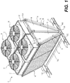
- a heat exchanger assembly 10 in accordance with an embodiment of the present technology.
- the heat exchanger assembly 10 is a dry cooler 10.
- any other suitable type of heat exchanger assembly e.g., a condenser, a chiller may be constructed in the manner that will be described below.
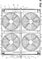
- the dry cooler 10 comprises a frame 12 which supports the dry cooler 10 on a support surface (e.g., a roof of a building), a plurality of heat exchanger panels 14 for exchanging heat with air flowing therethrough, and a plurality of fan assemblies 16 for pulling air through the heat exchanger panels 14 and discharging air from an interior space 25 of the dry cooler 10.
- a plurality of enclosing panels 18, 19 are also affixed to the frame 12 to define in part the interior space 25 of the dry cooler 10.
- the dry cooler 10 is also provided with casings 20 (each one associated with a respective one of the fan assemblies 16) to attenuate sound emissions generated by the dry cooler 10.
- a significant source of sound emission in a conventional dry cooler 2010 has been found to be caused by a "blade-passing effect" which involves part of a fan impeller 2012 of the dry cooler 2010 passing over a plate member 2014 disposed atop an upper end 2016 of a heat exchanger panel 2018.
- FIG. 18 which illustrates a cross-section of the conventional dry cooler 2010, a fluid flow analysis has shown that the proximity of the fan impeller 2012 to the plate member 2014 causes the flow of air within the dry cooler 2012 to be turbulent at zone TZ between the fan impeller 2012 and the plate member 2014.
- This turbulent flow has been identified as a significant source of noise produced by the conventional dry cooler 2010, in addition to generating significant vibrations which can negatively affect the life cycle of certain components of the dry cooler 2010. It should be pointed out that the blade-passing effect is in part a result of a desire to produce a narrower dry cooler 2010 (which makes it easier to transport and affords more space in the environment in which it is installed) while simultaneously having a fan impeller 2012 of a significant diameter to improve the efficiency of the dry cooler 2010. As will be described below, the casings 20 of the dry cooler 10 alleviate this blade-passing effect such that the dry cooler 10 is relatively quiet in comparison to the conventional dry cooler 2010.
- the frame 12 is configured to support various components of the dry cooler 10.
- the frame 12 comprises two legs 1030 laterally spaced apart from one another and which support the dry cooler 10 on the support surface.
- Each of the legs 1030 extends from a first end to a second end and has opposite end portions 1034 and a central portion 1037 between the end portions 1034.
- the end portions 1034 of each of the legs have a U-shaped cross-section while the central portion 1037 has a generally planar configuration forming a wall that extends along a plane extending vertically and parallel to the legs 1030.
- the dry cooler 10 may include wheels 1049 (e.g., caster wheels) ( FIG. 5 ) that are connected to the end portions 1034 of the legs 1030 such that the dry cooler 10 can be more easily displaced. For instance, this may facilitate moving the dry cooler 10 in/out of a container for transport.
- wheels 1049 e.g., caster wheels
- each of the legs 1030 has a cut-out configured to support therein part of the lower transversal member 1035. To that end, the cut-out has a shape and dimensions designed to receive the lower transversal member 1035.
- a pair of bracing members 1032 also extend laterally (i.e., parallel to and spaced apart from the lower transversal member) to interconnect the legs 1030. More specifically, the end portions 1034 of each of the legs 1030 have a rectangular groove for receiving a respective one of the bracing members 1032.
- the bracing members 1032 may be connected to the legs 1030 in any suitable way. In this example, the bracing members 1032 are fastened (e.g., welded) to the legs.
- the bracing members 1032 are positioned such that the lower transversal member 1035 is disposed between the bracing members 1032.
- the bracing members 1032 may be used to lift the dry cooler 10 via a forklift or other work vehicle, with the forks thereof being engaged within the cavity of each of the bracing members.
- a plurality of angular members 1052 are located between the legs 1030 and are configured to support the heat exchanger panels 14 of the dry cooler 10.
- four angular members 1052 are provided, with each angular member 1052 being disposed between a respective one of the bracing members 1032 and the lower transversal member 1035 such that two of the angular members 1052 are located on one side of the lower transversal member 1035 while the other two angular members 1052 are located on the opposite side of the lower transversal member1035.
- each of the angular members 1052 is connected to a respective one of the legs 1030 and to the lower transversal member 1035.
- each angular member 1052 could be connected solely to the lower transversal member 1035.
- the angular members 1052 have an angular configuration for conforming to the orientation of lower ends 24 of the heat exchanger panels 14.
- each angular member 1052 includes two upwardly oriented faces that are transversal (e.g., perpendicular) to one another and converge at a junction.
- the angular member is a bent component such that the junction is a bend in the angular member.
- the frame 12 further comprises three upstanding members 1036 laterally spaced apart from one another and extending upwardly (e.g., vertically) from the lower transversal member 1035.
- each of the upstanding members 1036 extends from a lower end portion 1050 that is connected to the lower transversal member 1050 to an upper end portion 1051.
- the upstanding members 1036 can be connected to the lower transversal member 1035 in any suitable way.
- fasteners e.g., bolts
- fasteners fasten a flange 141 at the lower end portion 1050 of each of the upstanding members 1036 to the lower transversal member 1035.
- An upper transversal member 1038 extending laterally and connecting the upper end portions 1051 of the upstanding members 1036, is disposed above the lower transversal member 1035.
- the upper transversal member 1038 is connected to the upstanding members 1036 in any suitable way (e.g., welded).
- An upper frame assembly 1045 is affixed to the upper transversal member 1038 and is configured to support the casings 20.
- the upper frame assembly 1045 comprises three upper retaining members 1040 which extend transversally to the upper transversal member 1038 and parallel to the legs 1030.
- the upper retaining members 1040 are laterally spaced apart from one another and are connected to the upper transversal member 1038. More specifically, an underside of each of the upper retaining members 1040 has a cut-out of an appropriate shape and size for receiving part of the upper transversal member 1038.
- the lower transversal member 1035, the upstanding members 1036, the upper transversal member 1038 and the upper retaining members 1040 are tubular, defining an interior space therein. This may allow the frame to support a greater load than if the members were made of sheet metal as is typically the case in conventional dry cooler assemblies.
- the heat exchanger panels 14 are mounted to the frame 12 and configured to exchange heat with air flowing therethrough.
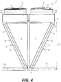
- the dry cooler 10 includes two heat exchanger panels 14, each being disposed on opposite sides of a vertical plane extending through the upstanding members 1036 of the frame 12, such that the heat exchanger panels 14 are arranged on each side of the lower transversal member 1035 of the frame 12.
- the lower end 24 of each heat exchanger panel 14 is supported by a respective one of the angular members 1052 of the frame 12 while an upper end 26 of each heat exchanger panel 14 is affixed to the upper frame assembly 1045.
- each of the heat exchanger panels 14 is connected to the ends of upper retaining members 1040 via fasteners (e.g., bolts).
- the lower end 24 of each of the heat exchanger panels 14 is supported by at least one of the angular members 1052 of the frame 12 such that the lower end 24 of each of the heat exchanger panels 14 is disposed between the bracing members 1032 of the frame 12.
- the lower end 24 of each of the heat exchanger panels 14 is fastened (e.g., bolted) to the angular members 1052.
- each of the heat exchanger panels 14 is disposed in an inclined orientation such that the upper and lower ends 24, 26 thereof are offset from one another.
- the two heat exchanger panels 14 are disposed in a V-configuration such that a distance between the upper ends 26 of the heat exchanger panels 14 is greater than a distance between the lower ends 24 of the heat exchanger panels 14.
- an angle formed between the heat exchanger panels 14 may be approximately 50°. This configuration reduces the footprint, or amount of ground space occupied by the dry cooler 10 and facilitates its transport, notably in shipping containers, or heavy-duty trailers, and the like.
- each of the outer fan supporting members 1015 is connected to respective ones of the heat exchanger panels 14 and are configured to support respective ones of the fan assemblies 16.
- the outer fan supporting members 1015 are provided to support an outer part of a corresponding one of the fan assemblies 16 due to a significant diameter of a fan impeller thereof which extends beyond the innermost point of an upper end 26 of the corresponding heat exchanger panel 14.
- each of the outer fan supporting members 1015 is disposed vertically above the upper end 26 of one of the heat exchanger panels 14.
- the upper end 26 of each heat exchanger panel 14 is disposed vertically below two of the outer fan supporting members 1015.
- Each outer fan supporting member 1015 is generally elongated and extends laterally (i.e., parallel to the upper transversal member 1038).
- Each outer fan supporting member 1015 has a flat plate portion 1016 and two lip portions 1018 (only one of which is shown in the Figures) extending downwardly and perpendicularly from the flat plate portion 1016. Both the flat plate portion 1016 and the lip portions 1018 extend along an entire length of the outer fan supporting member 1015.
- the flat plate portion 1016 is configured for affixing the corresponding fan assembly 16 thereto.
- the flat plate portion 1016 is provided with openings for receiving corresponding fasteners therein to affix the fan assembly 16 to the flat plate portion 1016.
- the innermost lip portion 1018 is affixed to the upper end 26 of the corresponding heat exchanger panel 14.
- each outer fan supporting member 1015 may be provided instead of four, with each outer fan supporting member 1015 extending above the upper end 26 of one of the heat exchanger panels 14.
- the heat exchanger panel 14 comprises a tubing arrangement 28 for circulating fluid therein, best seen in FIG. 2 .
- the fluid circulated in the tubing arrangement 28 is water; however, it is contemplated that other fluids or additional fluids (e.g., glycol) could circulate within the tubing arrangement 28 as well.
- the fluid enters the tubing arrangement 28 through a fluid intake 30, and exits the tubing arrangement through a fluid outtake 32.
- heat is transferred from water circulating in the tubing arrangement 28 to the air being pulled into the dry cooler10.
- the water circulating in the tubing arrangement 28 is cooled while, conversely, the air pulled into the dry cooler 10 is heated.
- the heat exchanger panel 14 also comprises a plurality of fins 33 in thermal contact with the tubing arrangement 28 to facilitate heat exchange between fluid circulating in the tubing arrangement 28 and air pulled into the dry cooler 10.
- the fins 33 are spaced apart from one another for air to flow therebetween and into the interior space 25 of the dry cooler 10.
- each heat exchanger panel 14 may be replaced by a plurality of heat exchanger panels (e.g., two heat exchanger panels) arranged to be laterally-adjacent to one another (i.e., disposed side-by-side) to form a series of laterally-adjacent heat exchanger panels.
- each series of laterally-adjacent heat exchanger panels would thus be disposed on opposite sides of the vertical plane extending through the upstanding members 1036 of the frame 12.
- the enclosing panels 18, 19 are connected to the frame 12 and define in part the interior space 25 of the dry cooler 10. More specifically, the enclosing panels 18, 19 define in part the lateral outer boundaries of the interior space 25 of the dry cooler 10 and also sub-divide the interior space 25 into sub-compartments, each sub-compartment being associated with a respective one of the fan assemblies 16.
- the enclosing panels 18, 19 include side enclosing panels 18 and middle enclosing panels 19 which extend perpendicularly to one another.
- the side enclosing panels 18 generally extend along a longitudinal plane (extending parallel to the legs 1030 of the frame 12) while the middle enclosing panels 19 generally extend along a lateral plane perpendicular to the longitudinal plane.
- the dry cooler 10 includes six side enclosing panels 18 and two middle enclosing panels 19.
- Each of the side enclosing panels 18 is connected to a respective one of the upstanding members 1036 of the frame 12, to an adjacent portion of an upper retaining member 1040, and to a respective one of the heat exchanger panels 14. As such, each upstanding member 1036 of the frame 12 is connected to two of the side enclosing panels 18.
- the side enclosing panels 18 which are disposed at the lateral extremities of the dry cooler 10 define outer walls of the dry cooler 10.
- the side enclosing panels 18 which are disposed between the lateral extremities of the dry cooler 10, namely between laterally-adjacent ones of the fan assemblies 16, define inner walls of the dry cooler 10 that sub-divide the interior space of the dry cooler 10 into laterally-adjacent sub-compartments.
- the side enclosing panels 18 are generally triangular in shape.
- Each of the middle enclosing panels 19 is connected to adjacent ones of the upstanding members 1036 of the frame 12, to an adjacent portion of the upper transversal member 1038 and to the lower transversal member 1035.
- the middle enclosing panels 19 thus define inner walls of the dry cooler 10 that sub-divide the interior space 25 of the dry cooler 10 into longitudinally-adjacent sub-compartments.
- the middle enclosing panels 19 and the side enclosing panels 18 which are disposed between the lateral extremities of the dry cooler 10 define the inner walls of the dry cooler 10 which sub-divide the interior space 25 of the dry cooler 10, and together with the other side enclosing panels 18 allow for each fan assembly 16 to have an isolated volume within which to pull air into and evacuate air therefrom.
- the middle enclosing panels 19 are generally rectangular.
- the fan assemblies 16 are disposed above and mounted to the casings 20 such that the casings 20 are disposed between the fan assemblies 16 and the upper ends 26 of the heat exchanger panels 14.
- each fan assembly 16 is configured identically in this embodiment, only one of the fan assemblies 16 will be described in detail herein. It is understood that the same description applies to the other fan assemblies 16.
- the fan assembly 16 comprises a fan mount 34 and a fan impeller 36 connected thereto (shown in FIGs. 15 , 16 ).
- the fan mount 34 has an outer flange portion 44 and an annular portion 42 extending upwardly from the outer flange portion 44.
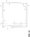
- the outer flange portion 44 of the fan mount 34 is connected to an upper end 47 of the corresponding casing 20, while the fan impeller 36 connects to the fan mount 34 via a motor 38 ( FIG. 12 ) that is supported by the annular portion 42 of the fan mount 34.
- a grill 40 covers and is affixed to the upper end of the annular portion 42 of the fan mount 34 and supports the motor 38 centrally thereof.
- the fan impeller 36 is rotatable by the motor 38 about a fan rotation axis FA extending generally vertically (i.e., parallel to the upstanding members 1036 of the frame 12).
- the fan impeller 36 is of a significant size to provide the dry cooler 10 with efficient performance.
- the fan impeller 36 has a diameter D of 950 mm.
- the fan impeller 36 is sized and positioned such that part of the fan impeller 36 rotates vertically above the upper end 26 of a corresponding one of the heat exchanger panels 14.
- the fan impeller 36 is surrounded by the annular portion 42 of the fan mount 34.
- the fan impeller 36 may have an even greater diameter in other embodiments.
- a larger fan impeller may be provided generally centered between the two heat exchanger panels disposed in the V-configuration.
- the fan assemblies 16 are thus arranged to evacuate heated air upwardly from the interior space 25 of the dry cooler 10.
- rotation of the fan impeller 36 of each fan assembly 16 causes ambient air to be pulled into dry cooler 10 through the corresponding heat exchanger panel 14.
- heat is transferred from fluid circulating in the tubing arrangement 28 of the heat exchanger panel 14 to the air, such that the air becomes heated.
- the heated air is then rejected upwardly from the interior space 25 of the dry cooler 10 through the fan assembly 16.
- the dry cooler 10 may have a plurality of fan assemblies arranged laterally-adjacent to one another to form a single row of laterally-adjacent fan assemblies.
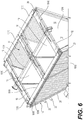
- each casing 20 is mounted to the upper frame assembly 1045. Specifically, each casing 20 is disposed between the upper frame assembly 1045 and a corresponding one of the fan assemblies 16. As such, each casing 20 is positioned between the corresponding fan assembly 16 and the upper end 26 of the corresponding heat exchanger panel 14, thus distancing the fan impeller from the outer fan supporting member 1015 disposed above the upper end 26 of the heat exchanger panel 14. This increased spacing between the fan impeller 36 and the outer fan supporting members 1015 results in a reduction in the turbulence and velocity of air at the area between the fan impeller and the outer fan supporting member 1015 compared to the conventional dry cooler 2010 of FIGs.
- the distance created between the fan assembly 16 and the upper end 26 of the heat exchanger panel 14 allows for the installation of further means of noise reduction below the fan assembly 16 such as grids and the like, which can further reduce the blade-passing effect and sound generated by the dry cooler 10.
- each casing 20 is configured identically and therefore only one of the casings 20 will be described in detail herein. It is understood that the same description applies to the other casings 20.
- the casing 20 includes four upright wall members 50, 52, 54, 56 which define the outer walls and thus the outer shape of the casing 20.
- the upright wall members 50, 52, 54, 56 are affixed (e.g., welded) to one another to form the generally box-like shape of the casing 20.
- the two upright wall members 50, 54 extend generally parallel to one another while the two upright wall members 54, 56 extend generally parallel to one another (and perpendicularly to the upright wall members 50, 54).
- Each of the upright wall members 50, 52, 54, 56 has an upper lip portion 66 and a lower lip portion 68, and a central portion extending therebetween.
- the upper and lower lip portions 66, 68 of each of the upright wall member members 50, 52, 54, 56 extend perpendicularly to the central portion.
- the upper lip portions 66 of the upright wall members 50, 52, 54, 56 define an upper end 47 of the casing 20.
- the lower lip portions 68 of the upright wall members 50, 52, 54, 56 define a lower end 49 of the casing 20.
- the upper end 47 thus accommodates the fan mount 34 of the fan assembly 16 so as to secure the fan mount 34 (e.g., via fasteners) to the upper end 47, while the lower end 49 is disposed atop the upper frame assembly 1045 (atop the corresponding outer fan supporting member 1015 and two of the upper retaining members 1040) and secured thereto.
- the casing 20 is open from its upper end 47 and its lower end 49 so as to allow air to flow from the corresponding heat exchanger panel 14 towards the corresponding fan assembly 16.
- the casing 20 has a plurality of inner walls for guiding air from the heat exchanger panel 14 toward the fan assembly 16.
- the inner walls of the casing 20 include upright inner walls 58, 59, 61 defined by the upright wall components 50, 52, 54 respectively.
- the upright inner walls 58, 61 are parallel to one another while the upright inner wall 59 extends transversally to the upright inner walls 58, 61.
- Another inner wall 62 of the casing 20 is defined by a spoiler 60 of the casing 20 which is affixed (e.g., welded) to the upright wall member 56 and thus substantially covers an inner wall 64 of the upright wall member 56 ( FIG. 11 ).
- the upright inner wall 59 faces the inner wall 62.
- the inner walls 58, 59, 61 and the spoiler 60 of the casing 20 are arranged so as to define in part the interior space 25 of the dry cooler 10.
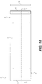
- the spoiler 60 is provided to modify the dynamics of air flow between the heat exchanger panel 14 and the fan assembly 16. As shown in FIG. 11 , the spoiler 60 has a lower portion 70 and a sloped portion 72 extending at angle to the lower portion 70. Notably, the lower portion 70 extends generally horizontally while the sloped portion 72 extends at an acute angle relative to the lower portion 70.
- the sloped portion 72 defines the inner wall 62 of the casing 20 and therefore the inner wall 62 may be referred to as a sloped wall 62.
- the sloped wall 62 is oriented to extend outwardly away from the fan rotation axis FA of the corresponding fan assembly 16.
- a distance between an upper end 76 of the sloped wall 62 and the fan rotation axis FA of the corresponding fan assembly 16 is greater than a distance between a lower end 78 of the sloped wall 62 and the fan rotation axis FA.
- the sloped wall 62 is disposed adjacent to the upper end 26 of the corresponding heat exchanger panel 14 and extends generally parallel to the inclined orientation of the heat exchanger panel 14 such that part of the fan impeller 36 rotates vertically above the sloped wall 62.
- an angle ⁇ is formed between the sloped wall 62 of the casing 20 and a vertical plane VP extending laterally (parallel to the inner walls 59, 64).
- the angle ⁇ between the sloped wall 62 of the casing 20 and the vertical plane VP is about 25°.
- the angle ⁇ can be smaller or greater than 25° in other embodiments.
- the angle ⁇ may be between about 20° and about 40° inclusively, between about 20° and about 35° inclusively, or between about 20° and about 30° inclusively.
- the angular orientation of the sloped wall 62 of the casing 20 has been found to further decrease the turbulent flow of air generated by the blade-passing effect. Therefore, the angular orientation of the sloped wall 62 results in an even greater reduction in sound emission by the dry cooler 10 than if the fan impeller 36 were only distanced further from the outer fan supporting member 1015. Furthermore, this decrease in turbulent flow further optimizes air flow at the entrance of the fan assembly 16 (as air enters the fan assembly 16 from the heat exchanger panel 14) and increases the overall performance of the dry cooler 10. By the same token, the life span of the fan impeller 36 is extended due to the reduced turbulent air flow compared to conventional dry coolers such as the conventional dry cooler 2010 of FIGs. 17 and 18 , notably due to an accompanying reduction in vibrations.
- the casing 20 reduces turbulent air flow within the interior space 25, it also increases a height of the dry cooler 10.
- the casing 20 is configured to elevate the corresponding fan assembly 16 sufficiently to distance the fan impeller 36 from the upper end 26 of the corresponding heat exchanger panel 14 while simultaneously avoiding having an excessively tall dry cooler 10 which would be more difficult to accommodate during transportation thereof.
- a height HC ( FIG. 10 ) of the casing 20, measured from the upper end 47 to the lower end 49, is significant enough for the sloped wall 62 to extend over a sufficiently long distance and thus positively affecting air flow, but not so significant as to render difficult the transport and/or the storage of the dry cooler 10.
- a ratio of the height HC of the casing 20 over a diameter D of the fan impeller 36 is between 0.20 and 0.40.
- the ratio of the height HC of the casing 20 over a diameter D of the fan impeller 36 is approximately 0.30
- a ratio of the height HC of the casing 20 over a vertical distance ULV ( FIG. 4 ) between the upper and lower ends 24, 26 of the heat exchanger panel 14 is between 0.10 and 0.20.
- the ratio of the height HC of the casing 20 over the vertical distance ULV is approximately 0.15.
- the height H of the casing is about 320 mm.
- the height H of the casing may be between about 200 mm and 400 mm inclusively or between about 200 mm and 350 mm inclusively.
- the provision of the casing 20 allows the installation of a bigger fan impeller 36 on the dry cooler 10 which would otherwise cause excessive turbulent air flow within the dry cooler 10 if it were not for the presence of the casing 20.
- a bigger fan impeller 36 i.e., having a greater diameter
- the desirability of having a bigger fan impeller 36 also runs contrary to the desire of limiting the width of a dry cooler 10 to facilitate its transport (e.g., to more easily fit in a shipping container).
- the dry cooler 10 has a maximal width of about 2200 mm to fit in a shipping container.
- the casing 20 thus provides the dry cooler 10 with the possibility of having the fan impeller 36 of a significant size while also having the width of the dry cooler 10 be relative small.
- a ratio of the diameter D of the fan impeller 36 over a horizontal distance ULH ( FIG. 15 ) between the upper and lower ends 24, 26 of the corresponding heat exchanger panel 14 is between 0.80 and 1.20.
- the ratio of the diameter D of the fan impeller 36 over the horizontal distance ULH is approximately 0.90.
- the casing 20 is made of sheet metal.
- the sheet metal may be made of any other suitable, including for example one or more of steel, stainless steel, galvanized steel, aluminum, brass, zinc and the like.
Landscapes
- Engineering & Computer Science (AREA)
- Mechanical Engineering (AREA)
- General Engineering & Computer Science (AREA)
- Physics & Mathematics (AREA)
- Thermal Sciences (AREA)
- Geometry (AREA)
- Heat-Exchange Devices With Radiators And Conduit Assemblies (AREA)
Priority Applications (5)
| Application Number | Priority Date | Filing Date | Title |
|---|---|---|---|
| EP19315107.3A EP3786559B1 (en) | 2019-08-30 | 2019-08-30 | Heat exchanger assembly |
| DK19315107.3T DK3786559T3 (da) | 2019-08-30 | 2019-08-30 | Varmeveksleranordning |
| PL19315107T PL3786559T3 (pl) | 2019-08-30 | 2019-08-30 | Zespół wymiennika ciepła |
| US16/988,216 US11280341B2 (en) | 2019-08-30 | 2020-08-07 | Heat exchanger assembly |
| CN202010887265.3A CN112444144A (zh) | 2019-08-30 | 2020-08-28 | 热交换器组件 |
Applications Claiming Priority (1)
| Application Number | Priority Date | Filing Date | Title |
|---|---|---|---|
| EP19315107.3A EP3786559B1 (en) | 2019-08-30 | 2019-08-30 | Heat exchanger assembly |
Publications (2)
| Publication Number | Publication Date |
|---|---|
| EP3786559A1 EP3786559A1 (en) | 2021-03-03 |
| EP3786559B1 true EP3786559B1 (en) | 2022-01-12 |
Family
ID=68072288
Family Applications (1)
| Application Number | Title | Priority Date | Filing Date |
|---|---|---|---|
| EP19315107.3A Active EP3786559B1 (en) | 2019-08-30 | 2019-08-30 | Heat exchanger assembly |
Country Status (5)
| Country | Link |
|---|---|
| US (1) | US11280341B2 (da) |
| EP (1) | EP3786559B1 (da) |
| CN (1) | CN112444144A (da) |
| DK (1) | DK3786559T3 (da) |
| PL (1) | PL3786559T3 (da) |
Families Citing this family (6)
| Publication number | Priority date | Publication date | Assignee | Title |
|---|---|---|---|---|
| US11946667B2 (en) * | 2019-06-18 | 2024-04-02 | Forum Us, Inc. | Noise suppresion vertical curtain apparatus for heat exchanger units |
| JP7224475B2 (ja) * | 2019-08-07 | 2023-02-17 | 三菱電機株式会社 | チリングユニット |
| MX2022009800A (es) | 2022-08-09 | 2022-10-26 | Noriega Victor Manuel Aguilar | Intercambiador de calor. |
| CN115727686A (zh) * | 2022-11-16 | 2023-03-03 | 深圳市英维克科技股份有限公司 | 一种干式联合换热设备 |
| CN119289585A (zh) * | 2023-07-10 | 2025-01-10 | 开利公司 | 用于冷柜装置的室外机组和冷柜装置 |
| EP4506647A1 (en) * | 2023-08-09 | 2025-02-12 | Ovh | Dry cooler assembly and method of assembling thereof |
Citations (1)
| Publication number | Priority date | Publication date | Assignee | Title |
|---|---|---|---|---|
| US20040093880A1 (en) * | 2002-11-19 | 2004-05-20 | Jing Zheng | Dual evaporator air conditioning system and method of use |
Family Cites Families (28)
| Publication number | Priority date | Publication date | Assignee | Title |
|---|---|---|---|---|
| US2330653A (en) * | 1942-06-22 | 1943-09-28 | Wilson Engineering Corp | Unit heater |
| DE1126430B (de) * | 1957-09-09 | 1962-03-29 | Gea Luftkuehler Happel Gmbh | Luftgekuehlter Waermeaustauscher |
| US4688472A (en) | 1986-10-31 | 1987-08-25 | Carrier Corporation | Noise reduction spoiler for a damper |
| JP2767045B2 (ja) * | 1988-10-31 | 1998-06-18 | 臼井国際産業 株式会社 | ラジエータ用シュラウド |
| JPH0311114A (ja) * | 1989-06-09 | 1991-01-18 | Nippondenso Co Ltd | 熱交換器に付設されるファン装置 |
| JPH0735095A (ja) * | 1993-07-19 | 1995-02-03 | Matsushita Refrig Co Ltd | ファンモータ取付装置 |
| CN1137348C (zh) * | 1998-06-22 | 2004-02-04 | 开利公司 | 具有三种安装方式的空调机室内装置 |
| TW566073B (en) | 2003-04-11 | 2003-12-11 | Delta Electronics Inc | Heat-dissipating device and a housing thereof |
| US20060131101A1 (en) | 2004-12-17 | 2006-06-22 | Michael Crocker | Fan noise attenuator |
| US8789291B2 (en) * | 2005-09-08 | 2014-07-29 | Bridgewater LLC | Heat exchanger assembly with air mover |
| US9863434B2 (en) * | 2005-10-11 | 2018-01-09 | Steven C. Elsner | Fins, tubes, and structures for fin array for use in a centrifugal fan |
| WO2008113160A1 (en) | 2007-03-16 | 2008-09-25 | E.H. Price Ltd. | Single duct silencing terminal unit |
| US8210308B2 (en) | 2007-03-16 | 2012-07-03 | E.H. Price Ltd. | Sound attentuator |
| JP2010127594A (ja) * | 2008-12-01 | 2010-06-10 | Fujitsu General Ltd | 空気調和機の室外機 |
| DE102009027170A1 (de) | 2009-06-24 | 2010-12-30 | BSH Bosch und Siemens Hausgeräte GmbH | Externes Gebläse für Dunstabzugsvorrichtung |
| WO2012001735A1 (ja) | 2010-06-29 | 2012-01-05 | 三菱電機株式会社 | 空気調和機 |
| US8770340B2 (en) | 2011-11-16 | 2014-07-08 | Huntair, Inc. | Sound-absorptive panel for an air handling system |
| US8813908B1 (en) | 2013-03-08 | 2014-08-26 | Ford Global Technologies, Llc | HVAC blower with noise suppression features |
| US9335098B2 (en) * | 2013-03-12 | 2016-05-10 | Copper Core Limited | V-shaped heat exchanger apparatus |
| US10267527B2 (en) * | 2013-06-04 | 2019-04-23 | Mitsubishi Electric Corporation | Outdoor unit for an air-conditioning device |
| CN104654825B (zh) * | 2013-06-25 | 2017-06-23 | 国电龙源电力技术工程有限责任公司 | 具有△形通道空间的空冷单元的导流装置 |
| US10837720B2 (en) * | 2013-11-06 | 2020-11-17 | Trane International Inc. | Heat exchanger with aluminum tubes rolled into an aluminum tube support |
| CN103925742B (zh) * | 2014-04-18 | 2016-06-29 | 丹佛斯微通道换热器(嘉兴)有限公司 | 换热器及其制造方法、换热模块、换热装置和热源单元 |
| NL2014380B1 (nl) | 2015-03-02 | 2017-01-17 | Eco-Logical Entpr B V | Enthalpiewisselaar. |
| US10260772B2 (en) | 2016-02-24 | 2019-04-16 | VAW Systems Ltd. | Duct mounted sound attenuating baffle with an internally suspended mass layer |
| US20170276397A1 (en) | 2016-03-24 | 2017-09-28 | VAW Systems Ltd. | Sound Attenuating Baffle Including a Non-Eroding Liner Sheet |
| PL416695A1 (pl) | 2016-03-30 | 2017-10-09 | Vts Spółka Z Ograniczoną Odpowiedzialnością | Tłumik kulisowy instalacji wentylacyjnej |
| CN109059244A (zh) | 2018-07-23 | 2018-12-21 | 常州信息职业技术学院 | 一种电子设备用空调噪音降低设备 |
-
2019
- 2019-08-30 PL PL19315107T patent/PL3786559T3/pl unknown
- 2019-08-30 DK DK19315107.3T patent/DK3786559T3/da active
- 2019-08-30 EP EP19315107.3A patent/EP3786559B1/en active Active
-
2020
- 2020-08-07 US US16/988,216 patent/US11280341B2/en active Active
- 2020-08-28 CN CN202010887265.3A patent/CN112444144A/zh active Pending
Patent Citations (1)
| Publication number | Priority date | Publication date | Assignee | Title |
|---|---|---|---|---|
| US20040093880A1 (en) * | 2002-11-19 | 2004-05-20 | Jing Zheng | Dual evaporator air conditioning system and method of use |
Also Published As
| Publication number | Publication date |
|---|---|
| DK3786559T3 (da) | 2022-02-07 |
| US20210062817A1 (en) | 2021-03-04 |
| PL3786559T3 (pl) | 2022-03-28 |
| CN112444144A (zh) | 2021-03-05 |
| US11280341B2 (en) | 2022-03-22 |
| EP3786559A1 (en) | 2021-03-03 |
Similar Documents
| Publication | Publication Date | Title |
|---|---|---|
| EP3786559B1 (en) | Heat exchanger assembly | |
| EP2710868B1 (en) | Variable frequency drive heat sink assembly | |
| EP0343834B1 (en) | Zero cube transport refrigeration unit for straight trucks | |
| JP5467125B2 (ja) | 孵卵機 | |
| US4307778A (en) | Heat exchange unit having an internal support | |
| CN101688735B (zh) | 具有通风组件的制冷装置 | |
| RU2515530C2 (ru) | Устройство кондиционирования для охлаждения воздуха в шкафу для электронных устройств | |
| CN220541247U (zh) | 除湿机 | |
| US11415338B2 (en) | Heat exchanger assembly | |
| US11272637B2 (en) | Rack arrangement for a data center | |
| CN116345272B (zh) | 一种压缩制冷光纤激光器 | |
| US20090033186A1 (en) | Enclosure providing improved cooling for a heat-generating device | |
| JP6145651B2 (ja) | 自動販売機 | |
| EP3567324B1 (en) | Hvacr system including multi-positional and multi-use plenum fans | |
| CN220582587U (zh) | 除湿机 | |
| CN216930639U (zh) | 散热器安装结构及窗式空调器 | |
| CN114206079B (zh) | 散热器安装结构及窗式空调器 | |
| CN214492460U (zh) | 驻车空调 | |
| CN223187410U (zh) | 一种底置式冷藏面包车用冷凝器总成 | |
| CN116981236B (zh) | 一种散热型电气控制柜 | |
| CN216982404U (zh) | 一种轻量化散热支架 | |
| US9976757B2 (en) | Airfoil frame for computer room air conditioning unit | |
| CN1378770A (zh) | 开关外壳 | |
| US12535230B2 (en) | Compact dehumidifier assemblies | |
| WO2026031708A1 (zh) | 储能装置及充电系统 |
Legal Events
| Date | Code | Title | Description |
|---|---|---|---|
| STAA | Information on the status of an ep patent application or granted ep patent |
Free format text: STATUS: EXAMINATION IS IN PROGRESS |
|
| PUAI | Public reference made under article 153(3) epc to a published international application that has entered the european phase |
Free format text: ORIGINAL CODE: 0009012 |
|
| 17P | Request for examination filed |
Effective date: 20200703 |
|
| AK | Designated contracting states |
Kind code of ref document: A1 Designated state(s): AL AT BE BG CH CY CZ DE DK EE ES FI FR GB GR HR HU IE IS IT LI LT LU LV MC MK MT NL NO PL PT RO RS SE SI SK SM TR |
|
| AX | Request for extension of the european patent |
Extension state: BA ME |
|
| GRAP | Despatch of communication of intention to grant a patent |
Free format text: ORIGINAL CODE: EPIDOSNIGR1 |
|
| STAA | Information on the status of an ep patent application or granted ep patent |
Free format text: STATUS: GRANT OF PATENT IS INTENDED |
|
| GRAS | Grant fee paid |
Free format text: ORIGINAL CODE: EPIDOSNIGR3 |
|
| INTG | Intention to grant announced |
Effective date: 20211111 |
|
| GRAA | (expected) grant |
Free format text: ORIGINAL CODE: 0009210 |
|
| STAA | Information on the status of an ep patent application or granted ep patent |
Free format text: STATUS: THE PATENT HAS BEEN GRANTED |
|
| AK | Designated contracting states |
Kind code of ref document: B1 Designated state(s): AL AT BE BG CH CY CZ DE DK EE ES FI FR GB GR HR HU IE IS IT LI LT LU LV MC MK MT NL NO PL PT RO RS SE SI SK SM TR |
|
| REG | Reference to a national code |
Ref country code: GB Ref legal event code: FG4D |
|
| REG | Reference to a national code |
Ref country code: CH Ref legal event code: EP |
|
| REG | Reference to a national code |
Ref country code: DE Ref legal event code: R096 Ref document number: 602019010862 Country of ref document: DE |
|
| REG | Reference to a national code |
Ref country code: IE Ref legal event code: FG4D |
|
| REG | Reference to a national code |
Ref country code: DK Ref legal event code: T3 Effective date: 20220202 |
|
| REG | Reference to a national code |
Ref country code: AT Ref legal event code: REF Ref document number: 1462659 Country of ref document: AT Kind code of ref document: T Effective date: 20220215 |
|
| REG | Reference to a national code |
Ref country code: NL Ref legal event code: FP |
|
| REG | Reference to a national code |
Ref country code: LT Ref legal event code: MG9D |
|
| REG | Reference to a national code |
Ref country code: AT Ref legal event code: MK05 Ref document number: 1462659 Country of ref document: AT Kind code of ref document: T Effective date: 20220112 |
|
| PG25 | Lapsed in a contracting state [announced via postgrant information from national office to epo] |
Ref country code: SE Free format text: LAPSE BECAUSE OF FAILURE TO SUBMIT A TRANSLATION OF THE DESCRIPTION OR TO PAY THE FEE WITHIN THE PRESCRIBED TIME-LIMIT Effective date: 20220112 Ref country code: RS Free format text: LAPSE BECAUSE OF FAILURE TO SUBMIT A TRANSLATION OF THE DESCRIPTION OR TO PAY THE FEE WITHIN THE PRESCRIBED TIME-LIMIT Effective date: 20220112 Ref country code: PT Free format text: LAPSE BECAUSE OF FAILURE TO SUBMIT A TRANSLATION OF THE DESCRIPTION OR TO PAY THE FEE WITHIN THE PRESCRIBED TIME-LIMIT Effective date: 20220512 Ref country code: NO Free format text: LAPSE BECAUSE OF FAILURE TO SUBMIT A TRANSLATION OF THE DESCRIPTION OR TO PAY THE FEE WITHIN THE PRESCRIBED TIME-LIMIT Effective date: 20220412 Ref country code: LT Free format text: LAPSE BECAUSE OF FAILURE TO SUBMIT A TRANSLATION OF THE DESCRIPTION OR TO PAY THE FEE WITHIN THE PRESCRIBED TIME-LIMIT Effective date: 20220112 Ref country code: HR Free format text: LAPSE BECAUSE OF FAILURE TO SUBMIT A TRANSLATION OF THE DESCRIPTION OR TO PAY THE FEE WITHIN THE PRESCRIBED TIME-LIMIT Effective date: 20220112 Ref country code: ES Free format text: LAPSE BECAUSE OF FAILURE TO SUBMIT A TRANSLATION OF THE DESCRIPTION OR TO PAY THE FEE WITHIN THE PRESCRIBED TIME-LIMIT Effective date: 20220112 Ref country code: BG Free format text: LAPSE BECAUSE OF FAILURE TO SUBMIT A TRANSLATION OF THE DESCRIPTION OR TO PAY THE FEE WITHIN THE PRESCRIBED TIME-LIMIT Effective date: 20220412 |
|
| PG25 | Lapsed in a contracting state [announced via postgrant information from national office to epo] |
Ref country code: LV Free format text: LAPSE BECAUSE OF FAILURE TO SUBMIT A TRANSLATION OF THE DESCRIPTION OR TO PAY THE FEE WITHIN THE PRESCRIBED TIME-LIMIT Effective date: 20220112 Ref country code: GR Free format text: LAPSE BECAUSE OF FAILURE TO SUBMIT A TRANSLATION OF THE DESCRIPTION OR TO PAY THE FEE WITHIN THE PRESCRIBED TIME-LIMIT Effective date: 20220413 Ref country code: FI Free format text: LAPSE BECAUSE OF FAILURE TO SUBMIT A TRANSLATION OF THE DESCRIPTION OR TO PAY THE FEE WITHIN THE PRESCRIBED TIME-LIMIT Effective date: 20220112 Ref country code: AT Free format text: LAPSE BECAUSE OF FAILURE TO SUBMIT A TRANSLATION OF THE DESCRIPTION OR TO PAY THE FEE WITHIN THE PRESCRIBED TIME-LIMIT Effective date: 20220112 |
|
| PG25 | Lapsed in a contracting state [announced via postgrant information from national office to epo] |
Ref country code: IS Free format text: LAPSE BECAUSE OF FAILURE TO SUBMIT A TRANSLATION OF THE DESCRIPTION OR TO PAY THE FEE WITHIN THE PRESCRIBED TIME-LIMIT Effective date: 20220512 |
|
| REG | Reference to a national code |
Ref country code: DE Ref legal event code: R097 Ref document number: 602019010862 Country of ref document: DE |
|
| PG25 | Lapsed in a contracting state [announced via postgrant information from national office to epo] |
Ref country code: SM Free format text: LAPSE BECAUSE OF FAILURE TO SUBMIT A TRANSLATION OF THE DESCRIPTION OR TO PAY THE FEE WITHIN THE PRESCRIBED TIME-LIMIT Effective date: 20220112 Ref country code: SK Free format text: LAPSE BECAUSE OF FAILURE TO SUBMIT A TRANSLATION OF THE DESCRIPTION OR TO PAY THE FEE WITHIN THE PRESCRIBED TIME-LIMIT Effective date: 20220112 Ref country code: RO Free format text: LAPSE BECAUSE OF FAILURE TO SUBMIT A TRANSLATION OF THE DESCRIPTION OR TO PAY THE FEE WITHIN THE PRESCRIBED TIME-LIMIT Effective date: 20220112 Ref country code: EE Free format text: LAPSE BECAUSE OF FAILURE TO SUBMIT A TRANSLATION OF THE DESCRIPTION OR TO PAY THE FEE WITHIN THE PRESCRIBED TIME-LIMIT Effective date: 20220112 Ref country code: CZ Free format text: LAPSE BECAUSE OF FAILURE TO SUBMIT A TRANSLATION OF THE DESCRIPTION OR TO PAY THE FEE WITHIN THE PRESCRIBED TIME-LIMIT Effective date: 20220112 |
|
| PLBE | No opposition filed within time limit |
Free format text: ORIGINAL CODE: 0009261 |
|
| STAA | Information on the status of an ep patent application or granted ep patent |
Free format text: STATUS: NO OPPOSITION FILED WITHIN TIME LIMIT |
|
| PG25 | Lapsed in a contracting state [announced via postgrant information from national office to epo] |
Ref country code: AL Free format text: LAPSE BECAUSE OF FAILURE TO SUBMIT A TRANSLATION OF THE DESCRIPTION OR TO PAY THE FEE WITHIN THE PRESCRIBED TIME-LIMIT Effective date: 20220112 |
|
| 26N | No opposition filed |
Effective date: 20221013 |
|
| PG25 | Lapsed in a contracting state [announced via postgrant information from national office to epo] |
Ref country code: SI Free format text: LAPSE BECAUSE OF FAILURE TO SUBMIT A TRANSLATION OF THE DESCRIPTION OR TO PAY THE FEE WITHIN THE PRESCRIBED TIME-LIMIT Effective date: 20220112 |
|
| PG25 | Lapsed in a contracting state [announced via postgrant information from national office to epo] |
Ref country code: MC Free format text: LAPSE BECAUSE OF FAILURE TO SUBMIT A TRANSLATION OF THE DESCRIPTION OR TO PAY THE FEE WITHIN THE PRESCRIBED TIME-LIMIT Effective date: 20220112 |
|
| REG | Reference to a national code |
Ref country code: CH Ref legal event code: PL |
|
| PG25 | Lapsed in a contracting state [announced via postgrant information from national office to epo] |
Ref country code: LU Free format text: LAPSE BECAUSE OF NON-PAYMENT OF DUE FEES Effective date: 20220830 Ref country code: LI Free format text: LAPSE BECAUSE OF NON-PAYMENT OF DUE FEES Effective date: 20220831 Ref country code: CH Free format text: LAPSE BECAUSE OF NON-PAYMENT OF DUE FEES Effective date: 20220831 |
|
| REG | Reference to a national code |
Ref country code: BE Ref legal event code: MM Effective date: 20220831 |
|
| P01 | Opt-out of the competence of the unified patent court (upc) registered |
Effective date: 20230513 |
|
| PG25 | Lapsed in a contracting state [announced via postgrant information from national office to epo] |
Ref country code: IT Free format text: LAPSE BECAUSE OF FAILURE TO SUBMIT A TRANSLATION OF THE DESCRIPTION OR TO PAY THE FEE WITHIN THE PRESCRIBED TIME-LIMIT Effective date: 20220112 Ref country code: IE Free format text: LAPSE BECAUSE OF NON-PAYMENT OF DUE FEES Effective date: 20220830 |
|
| PG25 | Lapsed in a contracting state [announced via postgrant information from national office to epo] |
Ref country code: BE Free format text: LAPSE BECAUSE OF NON-PAYMENT OF DUE FEES Effective date: 20220831 |
|
| PGFP | Annual fee paid to national office [announced via postgrant information from national office to epo] |
Ref country code: NL Payment date: 20230828 Year of fee payment: 5 |
|
| PGFP | Annual fee paid to national office [announced via postgrant information from national office to epo] |
Ref country code: PL Payment date: 20230821 Year of fee payment: 5 Ref country code: DK Payment date: 20230810 Year of fee payment: 5 |
|
| PG25 | Lapsed in a contracting state [announced via postgrant information from national office to epo] |
Ref country code: CY Free format text: LAPSE BECAUSE OF FAILURE TO SUBMIT A TRANSLATION OF THE DESCRIPTION OR TO PAY THE FEE WITHIN THE PRESCRIBED TIME-LIMIT Effective date: 20220112 |
|
| PG25 | Lapsed in a contracting state [announced via postgrant information from national office to epo] |
Ref country code: MK Free format text: LAPSE BECAUSE OF FAILURE TO SUBMIT A TRANSLATION OF THE DESCRIPTION OR TO PAY THE FEE WITHIN THE PRESCRIBED TIME-LIMIT Effective date: 20220112 Ref country code: HU Free format text: LAPSE BECAUSE OF FAILURE TO SUBMIT A TRANSLATION OF THE DESCRIPTION OR TO PAY THE FEE WITHIN THE PRESCRIBED TIME-LIMIT; INVALID AB INITIO Effective date: 20190830 |
|
| PG25 | Lapsed in a contracting state [announced via postgrant information from national office to epo] |
Ref country code: MT Free format text: LAPSE BECAUSE OF FAILURE TO SUBMIT A TRANSLATION OF THE DESCRIPTION OR TO PAY THE FEE WITHIN THE PRESCRIBED TIME-LIMIT Effective date: 20220112 |
|
| REG | Reference to a national code |
Ref country code: DK Ref legal event code: EBP Effective date: 20240831 |
|
| REG | Reference to a national code |
Ref country code: NL Ref legal event code: MM Effective date: 20240901 |
|
| PG25 | Lapsed in a contracting state [announced via postgrant information from national office to epo] |
Ref country code: NL Free format text: LAPSE BECAUSE OF NON-PAYMENT OF DUE FEES Effective date: 20240901 |
|
| PG25 | Lapsed in a contracting state [announced via postgrant information from national office to epo] |
Ref country code: DK Free format text: LAPSE BECAUSE OF NON-PAYMENT OF DUE FEES Effective date: 20240831 |
|
| PGFP | Annual fee paid to national office [announced via postgrant information from national office to epo] |
Ref country code: DE Payment date: 20250828 Year of fee payment: 7 |
|
| PGFP | Annual fee paid to national office [announced via postgrant information from national office to epo] |
Ref country code: GB Payment date: 20250822 Year of fee payment: 7 |
|
| PGFP | Annual fee paid to national office [announced via postgrant information from national office to epo] |
Ref country code: FR Payment date: 20250822 Year of fee payment: 7 |
|
| PG25 | Lapsed in a contracting state [announced via postgrant information from national office to epo] |
Ref country code: TR Free format text: LAPSE BECAUSE OF FAILURE TO SUBMIT A TRANSLATION OF THE DESCRIPTION OR TO PAY THE FEE WITHIN THE PRESCRIBED TIME-LIMIT Effective date: 20220112 |
|
| PG25 | Lapsed in a contracting state [announced via postgrant information from national office to epo] |
Ref country code: PL Free format text: LAPSE BECAUSE OF NON-PAYMENT OF DUE FEES Effective date: 20240830 |