EP3786582A2 - Systèmes et procédés de correction d'erreurs dans des gyroscopes - Google Patents
Systèmes et procédés de correction d'erreurs dans des gyroscopes Download PDFInfo
- Publication number
- EP3786582A2 EP3786582A2 EP20175948.7A EP20175948A EP3786582A2 EP 3786582 A2 EP3786582 A2 EP 3786582A2 EP 20175948 A EP20175948 A EP 20175948A EP 3786582 A2 EP3786582 A2 EP 3786582A2
- Authority
- EP
- European Patent Office
- Prior art keywords
- fsr
- rotation rate
- resonator
- temperature
- bias
- Prior art date
- Legal status (The legal status is an assumption and is not a legal conclusion. Google has not performed a legal analysis and makes no representation as to the accuracy of the status listed.)
- Granted
Links
Images


Classifications
-
- G—PHYSICS
- G01—MEASURING; TESTING
- G01C—MEASURING DISTANCES, LEVELS OR BEARINGS; SURVEYING; NAVIGATION; GYROSCOPIC INSTRUMENTS; PHOTOGRAMMETRY OR VIDEOGRAMMETRY
- G01C19/00—Gyroscopes; Turn-sensitive devices using vibrating masses; Turn-sensitive devices without moving masses; Measuring angular rate using gyroscopic effects
- G01C19/58—Turn-sensitive devices without moving masses
- G01C19/64—Gyrometers using the Sagnac effect, i.e. rotation-induced shifts between counter-rotating electromagnetic beams
- G01C19/72—Gyrometers using the Sagnac effect, i.e. rotation-induced shifts between counter-rotating electromagnetic beams with counter-rotating light beams in a passive ring, e.g. fibre laser gyrometers
- G01C19/721—Details, e.g. optical or electronical details
-
- G—PHYSICS
- G01—MEASURING; TESTING
- G01C—MEASURING DISTANCES, LEVELS OR BEARINGS; SURVEYING; NAVIGATION; GYROSCOPIC INSTRUMENTS; PHOTOGRAMMETRY OR VIDEOGRAMMETRY
- G01C19/00—Gyroscopes; Turn-sensitive devices using vibrating masses; Turn-sensitive devices without moving masses; Measuring angular rate using gyroscopic effects
- G01C19/58—Turn-sensitive devices without moving masses
- G01C19/64—Gyrometers using the Sagnac effect, i.e. rotation-induced shifts between counter-rotating electromagnetic beams
- G01C19/72—Gyrometers using the Sagnac effect, i.e. rotation-induced shifts between counter-rotating electromagnetic beams with counter-rotating light beams in a passive ring, e.g. fibre laser gyrometers
- G01C19/727—Gyrometers using the Sagnac effect, i.e. rotation-induced shifts between counter-rotating electromagnetic beams with counter-rotating light beams in a passive ring, e.g. fibre laser gyrometers using a passive ring resonator
-
- G—PHYSICS
- G01—MEASURING; TESTING
- G01C—MEASURING DISTANCES, LEVELS OR BEARINGS; SURVEYING; NAVIGATION; GYROSCOPIC INSTRUMENTS; PHOTOGRAMMETRY OR VIDEOGRAMMETRY
- G01C19/00—Gyroscopes; Turn-sensitive devices using vibrating masses; Turn-sensitive devices without moving masses; Measuring angular rate using gyroscopic effects
- G01C19/58—Turn-sensitive devices without moving masses
- G01C19/64—Gyrometers using the Sagnac effect, i.e. rotation-induced shifts between counter-rotating electromagnetic beams
- G01C19/72—Gyrometers using the Sagnac effect, i.e. rotation-induced shifts between counter-rotating electromagnetic beams with counter-rotating light beams in a passive ring, e.g. fibre laser gyrometers
- G01C19/726—Phase nulling gyrometers, i.e. compensating the Sagnac phase shift in a closed loop system
Definitions
- the resonator fiber optic gyroscope is a navigation gyroscope that has a combination of low cost, small package size, and weight.
- the RFOG uses at least two optical signals, where one optical signal propagates around a resonator in the clockwise (CW) direction and the other optical signal propagates in the counter-clockwise (CCW) direction.
- CW clockwise
- CCW counter-clockwise
- the resonator is a ring resonator comprising a coil of optical fiber with layers of windings.
- the length of the optical fiber used in the coil may be many meters, and the coil may comprise many layers of the optical fiber.
- the optical fiber comprises a core covered by cladding.
- RFOGs are susceptible to errors which vary with temperature of the core of the optical fiber of the resonator.
- One such error occurs in bias which represents an offset error in measured rotation rate.
- a RFOG may indicate rotation that is due to such bias error.
- Bias varies in an RFOG with a resonator that is a coil of optical fiber due to several effects, many of which can be temperature sensitive, including for example, the non-linear Kerr effect or the magneto-optical Faraday Effect. In the former case, the Kerr effect introduces a bias proportional to a power difference between counterpropagating beams, which is temperature dependent.
- the temperature of a RFOG's resonator is measured. Because of the cladding and many layers of the optical fiber, the average temperature of the core of the optical fiber coil cannot be accurately measured. As a result, the model directly relying upon temperature cannot accurately compensate for bias as temperature varies.
- a method for correcting rotation rate output from a gyroscope due to at least one time varying parameter of at least one of a gyroscope and the gyroscope's environment comprises: determining free spectral range (FSR) and rotation rate frequency shift for a rotation around a center axis of a resonator of a resonant fiber optic gyroscope (RFOG); determining a corrected rotation rate frequency shift for a rotation around the center axis of the resonator of a resonant fiber optic gyroscope (RFOG) using the determined free spectral range frequency, the determined rotation rate frequency shift, and at least one of a: bias model dependent upon the at least one time varying parameter and a scale factor model dependent upon the at least one time varying parameter.
- FSR free spectral range
- RFOG resonant fiber optic gyroscope
- Embodiments of the invention described herein pertain to compensating for time varying changes to a gyroscope incorporating a resonator and/or to an environment in which the gyroscope is located, and which affect the resonator.
- the invention is described with respect to an RFOG, but applies to other type of gyroscopes with a passive resonator - such as an on chip resonator.
- the time varying changes to the gyroscope and its environment include, but are not limited to, gyroscope aging, humidity, ambient temperature, and ambient pressure.
- Some RFOGs determine both rotation rate and resonator free spectral range (FSR) of the RFOG.
- FSR free spectral range
- free spectral range frequency may be used interchangeably.
- Resonator FSR is inversely proportional to the average temperature of a resonator, e.g. the average temperature of the core of the fiber coil.
- resonator FSR can be used to generate model(s) that compensate for RFOG errors arising due to temperature variations.
- FSR can be used with such model(s) to more accurately determine rotation rate by removing effects dependent upon resonator temperature. Such temperature effects may appear in RFOG bias and/or RFOG scale factor.
- an exemplary RFOG configured to generate both rotation rate and FSR will be described.
- FIG. 1A is a block diagram of one embodiment of a resonator fiber optic gyroscope (RFOG) 100 configured to generate both rotation rate and free spectral range.
- RFOG 100 comprises a first laser source 110 and second laser source 112 each coupled to a fiber optic resonator 120 by at least one first optical coupler 122.
- RFOG 100 further comprises a first resonance switching servo loop 130, a second resonance switching servo loop 132, and a feed-forward rate processor 135, each of which are discussed further below.
- the RFOG 100 may also compromise a processing system 119 coupled to the feed-forward rate processor 135; however, in other embodiments, the feed-forward rate processor 135 may be combined with the processing system 119, e.g. so that there is either only the feed-forward rate processor 135 or the processing system 119.
- the processing system 119 and the feed-forward rate processor 135 each comprise processing circuitry, e.g . processor circuitry coupled to memory circuitry, application specific integrated circuitry, gate array circuitry, and/or other circuitry.
- the processing system 119 and the feed-forward rate processor 135 may be alternatively referred to respectively as processing circuitry and feed-forward rate processing circuitry.
- the resonator 120 of RFOG 100 is configured to rotate around a center axis 128.
- the rate of rotation (or rotation rate), ⁇ , 129 measured by the RFOG 100 is a rate of rotation 129 of the resonator 120 around the center axis 128.
- the first laser source 110 outputs a first optical signal 101 of laser light that is coupled into the resonator 120 by the at least one first optical coupler 122 and travels around the resonator 120 in a first direction.
- the first optical signal 101 is defined as traveling around the resonator 120 in a counter-clockwise (CCW) direction.
- the second laser source 112 outputs a second optical signal 102 of laser light that is coupled into the resonator 120 by the at least one first optical coupler 122 and travels around the resonator 120 in a second direction that is opposite to the first direction traveled by first optical signal 101.
- the second optical signal 102 is defined as traveling around the resonator 120 in a clockwise (CW) direction.
- the first laser source 110 and the second laser source 112 are each respectively controlled by the first resonance switching servo loop 130 and the second resonance switching servo loop 132 to maintain the frequencies of the first optical signal 101 and the second optical signal 102 at resonance frequencies of the resonator 120.
- the first laser source 110 launches the first optical signal 101 into the resonator 120 at a specific optical frequency (shown in Figure 1A as f ccw).
- f ccw the first optical signal 101 has a specific wavelength, ⁇ ccw (which for laser light can be a wavelength on the order of 1.5 microns, for example).
- the first optical signal 101 When the first optical signal 101 is tuned to a frequency f ccw such that the CCW resonator length is exactly an integer multiple of wavelengths ⁇ ccw propagating around the resonator 120, then the first optical signal 101 is said to be operating at a resonant frequency of the resonator 120 in the CCW direction (which can also be referred to as one of the resonant modes of the resonator 120). At this frequency, with each pass that the first optical signal 101 travels around the loop of the resonator 120, the first optical signal 101 is in phase with its previous pass and the optical power from each pass accumulates to a peak resonant intensity. Any deviation in f ccw from a resonance frequency will cause optical power within the resonator 120 to sum to less than the peak resonant intensity.
- the first laser source 110 and the second laser source 112 are controlled respectively by the first resonance switching servo loop 130 and the second resonance switching servo loop 132 to remain locked to different resonance modes with respect to each other. That is, if the first optical signal 101 is locked to a resonant frequency f oa (where an integer number, I, of wavelengths are propagating in the CCW direction around the resonator 120), then the second optical signal 102 is locked to a resonant frequency f ob (where an integer number, J ⁇ I, of wavelengths are propagating in the CW direction around the resonator 120).
- Adjacent resonant frequencies are separated from each other based on a function of the free spectral range (FSR) of the resonator 120, a difference referred to herein as f FSR .
- FSR free spectral range
- Figure 1B illustrates a diagram of one embodiment of resonant modes of a resonator of a resonating fiber optic gyroscope. Operation of the first laser source 110 and the second laser source 112 to produce the first optical signal 101 and the second optical signal 102 at adjacent resonant modes (shown at M 1 and M 2 ) is further illustrated by the intensity versus frequency graphs shown in Figure 1B . As shown generally at 160, the first optical signal 101 is driven to a frequency f ccw that is equal to the frequency f oa corresponding to a first resonant mode M 1 .
- the second optical signal 102 is driven to a frequency f cw equal to the frequency f ob corresponding to a second resonant mode M 2 .
- the frequency difference between the peak resonant intensity at mode M 1 and the peak resonant intensity at mode M 2 is equal to the f FSR .
- first laser source 110 and the second laser source 112 operate at adjacent resonant modes, respectively frequencies M 1 and M 2 , separated by one f FSR .
- first laser source 110 and the second laser source 112 are operated at respectively at frequencies M 1 and M 2 separated by other integer multiples of f FSR .
- the frequency f ccw of the first optical signal 101 is locked to a resonance frequency f oa by the first resonance switching servo loop 130 while the frequency f cw of the second optical signal 102 is locked to a resonance frequency f ob by the second resonance switching servo loop 132.
- this is accomplished by operating the first resonance switching servo loop 130 and the second resonance switching servo loop 132 as frequency locked loops.
- the first optical signal 101 is frequency or phase modulated to interrogate the resonator.
- a portion of the first optical signal 101 is coupled out of the resonator 120 by at least one second optical coupler 123 and delivered to a first photodetector 127, which measures the optical intensity of the coupled portion of the first optical signal 101. From this measurement, the first photodetector 127 produces a first resonance tracking signal 126, which is an electrical signal that varies as a function of the measured optical intensity.
- the output of the first photodetector 127 will not have a frequency component at the modulation frequency. To first order, the output of the first photodetector 127 at the modulation frequency will be proportional to small average optical frequency deviations from the resonance frequency.
- Deviation from resonance frequency f oa produces a tracking error at the modulation frequency reflected in the first resonance tracking signal 126.
- the first resonance switching servo loop 130 is configured to receive the first resonance tracking signal 126 at the modulation frequency and to output a first control signal 140 to the first laser source 110 that adjusts the frequency f ccw of the first optical signal 101 to drive the tracking error at the modulation frequency to zero (i.e., the first control signal 140 drives the first optical signal 101 to the desired resonance frequency).
- a portion of the second optical signal 102 is coupled out of the resonator 120 by the at least one second optical coupler 123 and delivered to a second photodetector 124, which measures the optical intensity of the coupled portion of the second optical signal 102.
- the second photodetector 124 produces a second resonance tracking signal 125, which is an electrical signal that varies as a function of the measured optical intensity.
- the output of the second photodetector 124 will not have a frequency component at the modulation frequency.
- the output of the second photodetector 124 at the modulation frequency will be proportional to small average optical frequency deviations from the resonance frequency. Deviation from resonance frequency f ob produces a tracking error at the modulation frequency reflected in the second resonance tracking signal 125.
- the second resonance switching servo loop 132 is configured to receive the second resonance tracking signal 125 and to output a second control signal 142 to laser source 112 that adjusts the frequency f cw of the second optical signal 102 to drive the tracking error at the modulation frequency to zero ( i.e., control signal 142 drives second optical signal 102 to the desired resonance frequency).
- the phase, or frequency, modulation applied within RFOG 100 prior to the resonator 120 to facilitate detection of when each of the optical signals are at a resonance mode is described by U.S. Patent 7,362,443 which is incorporated herein by reference in its entirety.
- the first resonance switching servo loop 130 and the second resonance switching servo loop 132 are referred to as "resonance switching" because, in some embodiments, the respective resonator modes used for the first optical signal 101 and the second optical signal 102 are periodically swapped. That is, after operating for a fixed period of time with the first optical signal 101 at resonance frequency f oa (Mode M 1 ) and the second optical signal 102 at resonance frequency f ob (Mode M 2 ), the first resonance switching servo loop 130 and the second resonance switching loop 132 will switch the first optical signal 101 from resonance frequency f oa to resonance frequency f ob while simultaneously switching the second optical signal 102 from resonance frequency f ob to resonance frequency f oa.
- FIG. 1B illustrates adjacent resonance modes for the first optical signal 101 and the second optical signal 102 under the condition that the resonator 120 is not experiencing any rotation (i.e., has an angular rotation rate of zero).
- the frequency shift f ⁇ between CW and CCW resonances in the resonator due to rotation is also referred to herein interchangeably as the "rotation rate frequency shift".
- the various resonance modes for second optical signal 102 traveling in the CW direction shown by curve 182
- the respective path lengths travelled by the second optical signal 102 and the first optical signal respectively travelling in the CW and CCW directions will no longer be equal, exhibiting a phenomenon known as the Sagnac effect.
- the Sagnac effect For example, if resonator begins rotating in the CCW direction, the distance that the first optical signal 101 must travel to complete one trip around the resonator 120 increases in length, while the distance that the second optical signal 102 must travel to complete one trip around the resonator 120 decreases in length.
- the number of wavelengths that fit within the CW and CCW paths become dissimilar, and therefore the resonance modes associated with each direction will no longer align with each other.
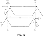
- Figure 1C illustrates a diagram of another embodiment of resonant modes of a resonator of a resonating fiber optic gyroscope.
- the frequencies of the first optical signal 101 and the second optical signal 102 have remained unchanged from the zero rotational resonance frequencies f oa and f ob .
- a resonance tracking error signal is present until the first and second resonance switching loops 130 and 132 control the laser frequencies to the new resonance frequencies to f 1 and f 2 .
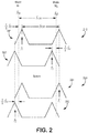
- FIG. 2 is a diagram illustrating one embodiment of resonant mode switching for a resonator fiber optic gyroscope. Operation of RFOG 100 during a first switching state is shown generally at 210 where the first optical signal 101 is locked to resonant mode M 1 and the second optical signal 102 is locked to the adjacent resonant mode M 2 . Due to rotation of the resonator 120, in the path traveled by the first optical signal 101 the frequency of resonance mode M 1 has shifted from the initial resonant frequency f oa to resonant frequency f 1 (as shown generally at 281). This shift is directly a function of the rate of rotation and equal to 1 ⁇ 2 f ⁇ .
- the frequency of resonance mode M 2 has shifted in the opposite direction from the initial resonant frequency f ob to a new resonant frequency f 2 (as shown generally at 282). This shift is also directly a function of the rate of rotation and equal to 1 ⁇ 2 f ⁇ .
- the first and second resonance switching servo loops 130 and 132 will adjust and drive the first optical signal 101 and the second optical signal 102 to maintain them at these new respective resonant frequencies f 1 and f 2 under a non-zero rotation rate.
- ⁇ f is the difference between the CCW and CW resonance frequencies of the resonator 120 which contains the shift due to the rotation rate and the FSR.
- ⁇ f includes a measurement of the rotation rate f ⁇ , but also includes a component of the FSR.
- the total length of the resonator 120 will expand and contract with temperature and for that reason FSR is a variable element that will change with the temperature. For that reason, the f FSR cannot be readily accounted for to obtain f ⁇ from ⁇ f .
- switching operation of RFOG 100 to the second switching state that swaps resonant modes between the first optical signal 101 and the second optical signal 102 leads to the development of a set of two independent linear equations with two unknowns, which permits solving for both f FSR and f ⁇ .
- RFOG 100 in the second switching state Operation of RFOG 100 in the second switching state is shown generally at 220 where the first optical signal 101 is now locked to resonant mode M 2 and the second optical signal 102 is locked to the adjacent resonant mode M 1 and the shifts in resonant frequencies in the CCW and CW directions due to rotation are shown respectively at 283 and 284
- calculation of ⁇ f + in the manner describe above by switching the first optical signal 101 and the second optical signal 102 between resonant modes M 1 and M 2 also serves to produce a value of 2 f ⁇ from which the effects of lineshape asymmetry gradient error have been canceled.
- ⁇ f a is the frequency shift in the first optical signal 101 due to lineshape asymmetry when the first optical signal 101 is locked to resonant mode M 1
- ⁇ f b is the frequency shift in the second optical signal 102 due to lineshape asymmetry when the second optical signal 102 is locked to resonant mode M 2 .
- the resonance switching servo loop 130 and resonance switching servo loop 132 repeatedly cycle between the first switching state and the second switching state so that during the first half of each cycle laser source 110 is locked to resonance mode M 1 and laser source 112 is locked to resonance mode M 2 , and during the second half of each cycle laser source 110 is locked to resonance mode M 2 and laser source 112 is locked to resonance mode M 1 .
- resonance switching servo loop 130 outputs the first control signal 140 equal to f 1 for the first half of each cycle, and equal to f 1 ⁇ for the second half of each cycle.
- resonance switching servo loop 132 outputs a control signal 142 equal to f 2 for the first half of each cycle, and equal to f 2 ⁇ for the second half of each cycle.
- the first control signal 140 and the second control signal 142 are also each provided to feed-forward rate processor 135, so that feed-forward rate processor 135 can calculate ⁇ f + and from that output rotation rate measurements ⁇ from rotation rate frequency shift value f ⁇ .
- feed-forward rate processor 135 may further utilize the values provided by the first control signal 140 and the second control signal 142 to calculate ⁇ f ⁇ and from that output FSR measurements f FSR .
- feed-forward rate processor 135 needs to continuously re-calculate ⁇ f + quickly enough to accommodate changes in FSR. Otherwise, if ⁇ f + is calculated from old data that does not represent current conditions, some fraction of FSR will enter into, and therefore corrupt, the rotation rate output. Resonant frequency switching needs to occur at a sufficiently high frequency so that FSR error is canceled out from the rotation rate calculations. However, switching too frequently also has drawbacks. During the finite period of time in which the servos 130 and 132 are actually performing the switch between resonant modes M 1 and M 2 , the frequency data carried by the first control signal 140 and the second control signal 142 becomes corrupted and unusable.
- Increasing the resonance switching frequency therefore also increases the fraction of corrupted and unusable data sent to feed-forward rate processor 135 per each resonance switching cycle, decreasing the usable fraction of data that feed-forward rate processor 135 has to work with per switching cycle.
- a completely independent consideration is the rate at which RFOG 100 needs to output fresh rotation rate measurement samples to satisfy system design criteria.
- the measurement sample output rate will likely be many orders of magnitude faster than the optimal resonance switching frequency. For example, where it may be optimal based on expected temperature dynamics for the switching state to be switched once per second (i.e., 1 Hz), for navigation applications, RFOG 100 may be called on to provide rotation rate measurement samples at a frequency of 1kHz or greater.
- feed-forward rate processor 135 also employs the feed forward mechanism.
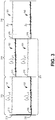
- Figure 3 is a diagram illustrating one embodiment of feed-forward rotation rate processing of a resonator fiber optic gyroscope.
- Curve 310 is a plot of frequency f 1 of the first optical signal 101 verses time while it is alternatively locked to the two CCW resonances
- curve 320 is a plot of frequency f 2 of the second optical signal 102 verses time while it is alternatively locked to the two CW resonances.
- f 1 and f 2 are assumed to be locked to a resonance frequency of the resonator 120, so f 1 and f 2 are indicative of both the frequencies of the first optical signal 101 and the second optical signal 102, and the measured CCW and CW resonance frequencies of the resonator 120, respectively.
- feed-forward rate processor 135 includes one or more digital signal processing units (or digital processing circuits) that calculate a first resonance frequency average ⁇ f 1 > based on the output of first optical signal 101 from the resonator 120, and a second resonance frequency average ⁇ f 2 > based on the output of the second optical signal 102 from the resonator 120, for each half of a switching cycle.
- an average ⁇ f ⁇ > may be calculated that is equal to ⁇ 2 f FSR >, which is proportional to the average FSR of the resonator 120 over the period of the full switching cycle 311.
- this ⁇ 2 f FSR > measured from the immediately prior switching cycle 311 is used by feed-forward rate processor 135 to cancel f FSR from current f 1 and f 2 resonant frequency measurements. That is, the ⁇ 2 f FSR > calculated for a past resonance switching cycle is fed-forward to and applied to the high frequency present frequency measurements to compensate for FSR during the current switching cycle, until a new ⁇ 2 f FSR > is calculated for the current switching cycle. This new ⁇ 2 f FSR > will then be fed-forward by feed-forward rate processor 135 for use to compensate for FSR for the next switching cycle.
- f 1 and f 2 are current resonant frequency measurements (since the frequencies of the second optical signal 102 and the first optical signal 101 are respectively locked to CW and CCW resonance frequencies of the resonator 120) provided from the outputs of the first resonance switching servo loop 130 and the second resonance switching servo loop 132
- ⁇ f ⁇ > is the fed-forward f FSR error correction (which may also include a lineshape asymmetry gradient correction as explained above) calculated from a past switching cycle.
- the rotation rate frequency shift value is not temperature compensated as discussed elsewhere herein.
- a previous full cycle of resonant frequency measurements comprises a first 1 ⁇ 2 cycle where the first optical signal 101 is locked to resonant mode M 1 and the second optical signal 102 is locked to resonant mode M 2 (shown at 312) and second 1 ⁇ 2 cycle where the first optical signal 101 is locked to resonant mode M 2 and the second optical signal 102 is locked to resonant mode M 1 (shown at 314).
- measurement samples resonant frequency switching states are indicated by the index reference "q" while the index "i” indicates resonant frequency f 1 , f 2 measurement samples produced by the first and second resonance switching servo loops 130 and 132.
- the higher frequency is represented by the lower of the two traces, consistent with the resonance frequency of mode M 2 being higher than the resonance frequency of mode M 1 .
- the average ⁇ f 1 > q-1 is the average of the measured resonant frequency f 1 values captured while the first optical signal 101 was locked to resonant mode M 2 during the full cycle 311 of resonant frequency measurements.
- the average ⁇ f 2 > q-1 is the average of the measured resonant frequency f 2 values captured while the second optical signal 102 was locked to resonant mode M 1 during the full cycle 311 of resonant frequency measurements.
- the average ⁇ f 1 > q-2 is the average of the resonant frequency f 1 values captured while optical beam 101 was locked to resonant mode M 1 during the full cycle 311 of resonant frequency measurements.
- the average ⁇ f 2 > q-2 is the average of the resonant frequency f 2 values captured while optical beam 102 was locked to resonant mode M 2 during the full cycle 311 of resonant frequency measurements. It should be noted that at 316, each of the resonant frequencies are flat-lined immediately after switching between modes M 1 and M 2 is initiated.
- f 1 values and f 2 values are blanked out and unused so as not to affect the calculation of the ⁇ f 1 > and ⁇ f 2 > averages.
- the two half-cycles 312 and 314 together form a full resonance switching cycle 311 from which a ⁇ f ⁇ > may be calculated as follows.
- An RFOG configured to generate both rotation rate and FSR, such as the one illustrated above, may be used to more accurately determine a temperature dependent rotation rate frequency shift by accounting for changes in RFOG bias and/or scale factor due to temperature.
- the temperature dependence of scale factor and/or bias may be characterized and stored in the RFOG 100 using model(s).
- the model(s) may be stored in the processing system 119.
- temperature dependent bias and temperature dependent scale factor can be modelled using FSR in lieu of temperature. Characterization of temperature dependent bias will first be addressed.
- Bias temperature dependence is characterized by determining bias versus one or more orders of FSR (e.g. one or more of FSR, FSR 2 , FSR 3 , etc.) and/or bias versus one or more orders of a derivative of FSR with respect to time (e.g. one or more of dFSR/dt, d 2 FSR/dt 2 , d 3 FSR/dt 3 , etc.).
- the orders of FSR and/or the orders of the derivative of FSR with respect to time may vary based upon RFOG design and/or the desired accuracy of rotation rate. Thus, bias and FSR must be determined with respect to changes in temperature or rates of change of temperature.
- FIG. 4A illustrates a diagram of one embodiment of a measurement system 440.
- the measurement system 440A comprises a heater 442 upon or in which the RFOG 400 can be placed.
- the heater 442 may be a hot plate or an oven.
- the heater 442 is configured to heat the RFOG 400, and particularly the resonator 120, as described herein to facilitate determination of temperature dependence of bias, and temperature dependence of scale factor.
- Determination of rotation rate versus one or more orders of FSR (e.g. one or more of FSR, FSR 2 , FSR 3 , etc.) and/or rotation rate versus one or more orders of a derivative of FSR with respect to time (e.g. one or more of dFSR/dt, d 2 FSR/dt 2 , d 3 FSR/dt 3 , etc.) may be performed as follows. Initially, a first set of measurements of the RFOG's rate of rotation 129 of the resonator 120 around the center axis 128 and FSR are taken over a temperature range.
- the resonator 120 of the RFOG 100 is fixedly positioned around its center axis 128 so that the resonator 120 has a known fixed first rotation rate, e.g. a zero rotation rate. Further, the center axis 128 may be pointed East or West, e.g. to diminish effects from the rotation of the Earth; otherwise a component corresponding to the Earth's rotation would have to be accounted for such measurements.
- the first set of measurements is stored in processing circuitry, e.g . other processing circuitry external to the RFOG 100.
- FIG. 4B illustrates a diagram of another embodiment of a measurement system 440B.
- the measurement system 440B comprises a heater 442 upon or in which the RFOG 400 can be placed.
- the heater 442 may be a hot plate or an oven.
- the heater 442 is configured to heat the RFOG 100, and particularly the resonator 120, as described herein.
- the RFOG 400 on or in the heater 442 are placed on a rotation system 444 (e.g. a rotation table) or the RFOG 400 on the rotation system 444 are placed in the heater 442.
- the measurement system 440B is used to rotate the RFOG 400 around its center axis 128 at fixed and/or variable rate(s) of rotation.
- rotation rate needs to be measured versus one or more orders of FSR and/or rotation rate versus one or more orders of a derivative of FSR with respect to time (e.g. one or more of dFSR/dt, d 2 FSR/dt 2 , d 3 FSR/dt 3 , etc.) in a manner described above but for one or more rotation rates (in the measurement range of the RFOG 400) that are different then the rotation rate used to characterize temperature dependent bias.
- a derivative of FSR with respect to time e.g. one or more of dFSR/dt, d 2 FSR/dt 2 , d 3 FSR/dt 3 , etc.
- the first set of measurements is made over and/or within the expected operating range of a corresponding order of temperature (that is the same order as the order of FSR).
- the first set of measurements are made over a corresponding expected temperature operating range (e.g. -55°C to 125°C or -40°C to 85°C) of the RFOG 100.
- measurements of a rotation rate versus the corresponding order FSR measurements and/or measurements of a rotation rate versus the order of derivative of FSR with respect to time can be made in equal increments or steps.
- the first set of measurements may include measurements of FSR made by varying temperature at fixed or varying rates with respect to time. For example, for the first order derivative of FSR with respect to time, RFOG temperature can be ramped up from a first temperature to a second temperature at a fixed rate, and then ramped down at the same or different fixed rate from the second temperature to the first temperature. As a result, positive and negative temperature slopes with respect to time are measured. Measurements can be made when varying a rate of change in temperature with respect to time to characterize higher order derivatives of FSR with respect to time.
- a second set of measurements of the RFOG's rate of rotation 129 of the resonator 120 around the center axis 128 and FSR are taken over a temperature range (which at least includes the temperature range used for the first set of measurements) at a known, fixed second rotation rate that is a non-zero rate of rotation and is different than the known, fixed second rotation rate.
- the center axis 128 may be pointed East or West, e.g. to diminish effects from the rotation of the Earth.
- the second set of measurements is taken by changing temperature at a fixed rate with respect to time and/or by varying a rate of change of temperature with respect to time - as discussed above.
- at least one additional bias component may be characterized which comprises an order of a derivative of a thermal spatial gradient across the resonator 120 with respect to time.
- the thermal spatial gradient may be measured with thermal sensors, e.g . thermocouples and/or thermistors placed at different locations of the resonator 120.
- thermal sensors e.g . thermocouples and/or thermistors placed at different locations of the resonator 120.
- a first set of at least one thermal sensor 131 may be placed on or by the resonator 120 diametrically opposite a second set of at least one thermal sensor 133 placed on or by the resonator 120.
- the thermal spatial gradient, ⁇ T may be measured between the inner and outer diameters of the optical fiber coil that forms the resonator 120.
- the first set of one or more thermal sensors may be placed on or by optical fiber(s) forming an inner diameter of the optical fiber coil and the second set of one or more thermal sensors may be placed (opposite the first set of at least one thermal sensor 131) on or by optical fiber(s) forming an outer diameter of the optical fiber coil.
- the sets of thermal sensors may be located elsewhere to characterize the foregoing or other thermal spatial gradients.
- This bias component (comprising order(s) of derivative of thermal spatial gradient data with respect to time) may be stored in the first set of measurements, e.g . as described elsewhere herein.
- the thermal spatial gradient can be induced in the resonator 120 by only activating heating elements in the heater 442 closer to one side of the resonator nearer to the first set of at least one thermal sensor 131 then the second set of at least one thermal sensor 133 (or vice versa).
- the thermal spatial gradient can be induced in the resonator 120 by generating more heat from heating elements in the heater 442 resonator nearer to the first set of at least one thermal sensor 131 then the heating elements nearer to the second set of at least one thermal sensor 133 (or vice versa).
- Coefficients of equations (or mathematical models) of temperature dependent bias and/or scale factor may be determined for each RFOG using corresponding measurement data.
- each of temperature dependent bias and temperature dependent scale factor can be modelled using a polynomial function having at least one term, where each term comprises: (a) at least one constant, and at least one of: (a) a power of FSR (e.g. one of FSR, FSR 2 , FSR 3 , etc.) multiplied by a corresponding constant; and (b) an order of a derivative of FSR with respect to time ( e.g. one of dFSR/dt, d 2 FSR/dt 2 , d 3 FSR/dt 3 , etc.) multiplied by a corresponding constant.
- FSR e.g. one of FSR, FSR 2 , FSR 3 , etc.
- the first measurement set must include a number of measurements taken equal to or greater than the number of constants to be solved (e.g. 5: k 1 through k 5 ).
- Bias FSR k 1 + k 2 * FSR + k 3 * FSR 2 + k 4 * dFSR / dt + k 5 * d ⁇ T / dt
- the foregoing model is exemplary and other models can be used, e.g. with different orders of FSR, different orders of derivative of FSR with respect to time, with order(s) of thermal spatial gradient, with different orders of thermal spatial gradient with respect to time, and/or without any term that is a function of thermal spatial gradient term.
- any coefficient of a constant term (e.g. k 1 ) and any coefficient multiplied by an order of FSR (e.g. k 2 and k 3 ) are determined using fitting. Fitting described herein may be, e.g. least square fitting.
- the bias is fitted with respect to measured FSR by changing the temperature (at a predetermined fixed rotation rate) in the first set of measurements. The number of determinations of bias with respect to FSR by varying temperature in the first measurement set must be equal or greater than the number of constants to be fitted or determined.
- bias must be measured at a minimum number of three different values of the FSR.
- many more points are used to get more confidence in the determination of the coefficients.
- a linear ramp of the temperature with continuous monitoring of the indicated rate gives hundreds or thousands of independent measurements to base the coefficient determination upon.
- k 3 a wide temperature range may be used, so that departures from a linear dependence may be observed.
- any coefficient of multiplied by an order of a derivative of FSR with respect to time (e.g. k 4 ) is determined using fitting.
- the bias is fitted with respect to the measured rate of change of the FSR with respect to time due to the corresponding derivative of temperature with respect to time (at a predetermined fixed rotation rate) in the first set of measurements.
- Coefficients of orders of thermal spatial gradient and orders of derivative of thermal spatial gradient can be determined in an analogous manner.
- temperature dependent scale factor may be modelled in analogously. All or a portion of the RFOG 100 (at least the resonator 120) is placed on the rotation system 444. Temperature is varied over the expected operating temperature range of the RFOG 100. At each temperature increment, rotation rate is measured for different known rotation rates within an expected operating rotation rate range of the RFOG, e.g. ⁇ 100 degrees/second; the rotation system 444 rotates the resonator 120 around its center axis 128 at such known rotation rates.
- Temperature dependent scale factor may be modelled using terms comprising a constant term, at least one term each of which comprises a coefficient multiplied by an order of FSR. Additionally, there may be at least one term each of which comprises a coefficient multiplied by an order of derivative of FSR with respect to time, at least one term each of which comprises a coefficient multiplied by an order of a spatial thermal gradient, and/or at least one term each of which comprises a coefficient multiplied by an order of a derivative of a spatial thermal gradient with respect to time.
- bias is subtracted from the measured rotation rate in the second set of measurement data.
- the bias is determined using a model whose coefficients have been solved in a manner described elsewhere herein. Then the resulting difference data is used to fit the constants in a manner as described elsewhere herein.
- the models for bias and scale factor are stored in the corresponding RFOG(s), e.g. in the processing system 119 of each RFOG.
- the term corrected rotation rate may be used for rotation rates corrected or compensated for varying temperature or other conditions.
- Figure 5 is a flow diagram illustrating one embodiment of a method 500 for determining a model for correcting time varying changes affecting a resonator of a gyroscope. For pedagogical purposes, the method 500 is illustrated with regards to temperature compensation of an RFOG.
- a predetermined fixed rotation rate may be a zero rotation rate.
- a temperature dependent bias model and a temperature dependent scale factor model determine at least one of: a temperature dependent bias model and a temperature dependent scale factor model.
- the at least one of the temperature dependent bias model and the temperature dependent scale factor model comprise at least a portion of a temperature dependent rotation rate model of an RFOG.
- Each of the temperature dependent bias model and the temperature dependent scale factor model comprises a term dependent upon the order of the FSR or dependent upon the order of derivative of the FSR with respect to time.
- store the determined at least one model in an RFOG which may be an RFOG for which rotation rate and FSR was characterized or another RFOG.
- Figure 6 is a flow diagram illustrating one embodiment of a method 600 for correcting time varying changes affecting a resonator of a gyroscope. For pedagogical purposes, the method 600 is illustrated with regards to temperature compensation of an RFOG.
- block 660 determine free spectral range and rotation rate frequency shift around a center axis of a resonator of an RFOG.
- block 662 determine a temperature compensated rotation rate frequency shift, or a temperature compensated rotation rate output, around the center axis of the resonator using the determined free spectral range frequency, the determined rotation rate frequency shift, and at least one of a: temperature dependent bias model and a temperature dependent scale factor model; each of the temperature dependent bias model and the temperature dependent scale factor model comprises a term dependent upon the order of the FSR or dependent upon the order of derivative of the FSR with respect to time.
- system elements, method steps, or examples described throughout this disclosure may be implemented on one or more computer systems, field programmable gate array (FPGA), or similar devices comprising a processor executing code to realize those elements, processes, or examples, said code stored on a non-transient data storage device. Therefore, other embodiments of the present disclosure may include elements comprising program instructions resident on computer readable media which when implemented by such computer systems, enable them to implement the embodiments described herein.
- computer readable media refers to tangible memory storage devices having non-transient physical forms.
- Non-transient physical forms may include computer memory devices, such as but not limited to punch cards, magnetic disk or tape, any optical data storage system, flash read only memory (ROM), non-volatile ROM, programmable ROM (PROM), erasable-programmable ROM (E-PROM), random access memory (RAM), or any other form of permanent, semi-permanent, or temporary memory storage system or device having a physical, tangible form.
- Program instructions include, but are not limited to computer-executable instructions executed by computer system processors and hardware description languages such as Very High Speed Integrated Circuit (VHSIC) Hardware Description Language (VHDL).
- VHSIC Very High Speed Integrated Circuit
- VHDL Hardware Description Language
Landscapes
- Physics & Mathematics (AREA)
- Engineering & Computer Science (AREA)
- Power Engineering (AREA)
- Optics & Photonics (AREA)
- Electromagnetism (AREA)
- General Physics & Mathematics (AREA)
- Radar, Positioning & Navigation (AREA)
- Remote Sensing (AREA)
- Gyroscopes (AREA)
Applications Claiming Priority (1)
| Application Number | Priority Date | Filing Date | Title |
|---|---|---|---|
| US16/519,768 US10914587B1 (en) | 2019-07-23 | 2019-07-23 | Systems and methods for correcting errors in gyroscopes |
Publications (3)
| Publication Number | Publication Date |
|---|---|
| EP3786582A2 true EP3786582A2 (fr) | 2021-03-03 |
| EP3786582A3 EP3786582A3 (fr) | 2021-03-24 |
| EP3786582B1 EP3786582B1 (fr) | 2022-05-11 |
Family
ID=70802760
Family Applications (1)
| Application Number | Title | Priority Date | Filing Date |
|---|---|---|---|
| EP20175948.7A Active EP3786582B1 (fr) | 2019-07-23 | 2020-05-21 | Systèmes et procédés de correction d'erreurs dans des gyroscopes |
Country Status (2)
| Country | Link |
|---|---|
| US (1) | US10914587B1 (fr) |
| EP (1) | EP3786582B1 (fr) |
Families Citing this family (4)
| Publication number | Priority date | Publication date | Assignee | Title |
|---|---|---|---|---|
| CN113739783B (zh) * | 2021-11-08 | 2022-03-01 | 华中光电技术研究所(中国船舶重工集团公司第七一七研究所) | 一种光纤陀螺振铃效应误差抑制系统及抑制方法 |
| US12492902B2 (en) | 2022-06-22 | 2025-12-09 | Honeywell International Inc. | Modulation methods and systems for non-reciprocal Kerr reduction in resonator fiber optic gyroscopes |
| CN115493622B (zh) * | 2022-09-29 | 2025-06-20 | 西北工业大学 | 一种基于模糊控制和高斯过程的半球谐振陀螺温补方法 |
| CN116734847B (zh) * | 2023-08-14 | 2023-10-31 | 中国人民解放军火箭军工程大学 | 一种激光捷联惯组温度补偿方法 |
Citations (3)
| Publication number | Priority date | Publication date | Assignee | Title |
|---|---|---|---|---|
| US7362443B2 (en) | 2005-11-17 | 2008-04-22 | Honeywell International Inc. | Optical gyro with free space resonator and method for sensing inertial rotation rate |
| US7372574B2 (en) | 2005-12-09 | 2008-05-13 | Honeywell International Inc. | System and method for stabilizing light sources in resonator gyro |
| US9772189B2 (en) | 2015-05-11 | 2017-09-26 | Honeywell International Inc. | Systems and methods for resonance switching resonator fiber optic gyroscopes (RFOGs) with feed-forward processing |
Family Cites Families (6)
| Publication number | Priority date | Publication date | Assignee | Title |
|---|---|---|---|---|
| US20070097374A1 (en) | 2005-11-01 | 2007-05-03 | Liu Ren-Young | IFOG modulation technique for real-time calibration of wavelength reference under harsh environment |
| US7912664B2 (en) | 2008-09-11 | 2011-03-22 | Northrop Grumman Guidance And Electronics Company, Inc. | Self calibrating gyroscope system |
| US8583371B1 (en) * | 2010-12-23 | 2013-11-12 | Lockheed Martin Corporation | Autonomous gyro temperature calibration |
| US8947671B2 (en) * | 2013-02-22 | 2015-02-03 | Honeywell International Inc. | Method and system for detecting optical ring resonator resonance frequencies and free spectral range to reduce the number of lasers in a resonator fiber optic gyroscope |
| US10228264B2 (en) * | 2016-09-02 | 2019-03-12 | Northrop Grumman Systems Corporation | Self-calibration of an inertial system |
| EP3447445A1 (fr) * | 2017-08-21 | 2019-02-27 | Tata Consultancy Services Limited | Systèmes et procédés permettant d'estimer les erreurs dans des capteurs gyroscopiques |
-
2019
- 2019-07-23 US US16/519,768 patent/US10914587B1/en active Active
-
2020
- 2020-05-21 EP EP20175948.7A patent/EP3786582B1/fr active Active
Patent Citations (3)
| Publication number | Priority date | Publication date | Assignee | Title |
|---|---|---|---|---|
| US7362443B2 (en) | 2005-11-17 | 2008-04-22 | Honeywell International Inc. | Optical gyro with free space resonator and method for sensing inertial rotation rate |
| US7372574B2 (en) | 2005-12-09 | 2008-05-13 | Honeywell International Inc. | System and method for stabilizing light sources in resonator gyro |
| US9772189B2 (en) | 2015-05-11 | 2017-09-26 | Honeywell International Inc. | Systems and methods for resonance switching resonator fiber optic gyroscopes (RFOGs) with feed-forward processing |
Also Published As
| Publication number | Publication date |
|---|---|
| US10914587B1 (en) | 2021-02-09 |
| US20210025709A1 (en) | 2021-01-28 |
| EP3786582A3 (fr) | 2021-03-24 |
| EP3786582B1 (fr) | 2022-05-11 |
Similar Documents
| Publication | Publication Date | Title |
|---|---|---|
| US9772189B2 (en) | Systems and methods for resonance switching resonator fiber optic gyroscopes (RFOGs) with feed-forward processing | |
| EP3786582A2 (fr) | Systèmes et procédés de correction d'erreurs dans des gyroscopes | |
| Lefèvre | The fiber-optic gyroscope: Challenges to become the ultimate rotation-sensing technology | |
| Lefèvre | The fiber-optic gyroscope, a century after Sagnac's experiment: The ultimate rotation-sensing technology? | |
| EP3336586B1 (fr) | Gyroscope à faisceau d'atomes | |
| Schreiber et al. | Variations in the Earth’s rotation rate measured with a ring laser interferometer | |
| KR101399423B1 (ko) | 광섬유 자이로 장치 및 그것의 온도 섭동에 의한 과도상태의 출력오차 보상방법, 광섬유 자이로 장치의 온도 섭동에 의한 과도상태의 출력오차 보상 값 산출방법 | |
| EP2246663B1 (fr) | Gyroscope optique commandé par laser doté d'une longueur de cohérence de source non négligeable | |
| US20230027677A1 (en) | Method for Determining a Change in a Rotational Orientation in the Space of an NMR Gyroscope, and NMR Gyroscope | |
| Pavlath | Fiber optic gyros past, present, and future | |
| US6181428B1 (en) | Closed loop fiber optic gyro with shupe effect compensation | |
| Di Virgilio et al. | Overcoming 1 part in 10 9 of earth angular rotation rate measurement with the G Wettzell data | |
| US10502585B2 (en) | Gyro rate computation for an interferometric fiber optic gyro | |
| JP6880834B2 (ja) | 磁気センサ、生体磁気測定装置 | |
| Korkishko et al. | Fiber optic gyro for space applications. Results of R&D and flight tests | |
| Wang et al. | Modeling and simulation of polarization errors in Sagnac fiber optic current sensor | |
| Chang et al. | Resonance asymmetry phenomenon in waveguide-type optical ring resonator gyro | |
| US8301407B2 (en) | Stabilized solid-state gyrolaser | |
| JP7825032B2 (ja) | 電子ゼーマン分裂を利用するデバイス | |
| Kublanova et al. | Study of an interferometric fiber-optic gyroscope with a birefringence modulator | |
| Pavlath | Challenges in the development of the IFOG | |
| JP2006528358A (ja) | 光ファイバ・ジャイロを備えるリアクション・ホイール・アセンブリ | |
| Çelikel | Construction and characterization of interferometric fiber optic gyroscope (IFOG) with erbium doped fiber amplifier (EDFA) | |
| Fateev et al. | Relativistic effects on moving clocks | |
| Sato et al. | Digital closed-loop thermal atomic beam interferometer for high-bandwidth, wide-dynamic-range, and simultaneous absolute sensing of acceleration and rotation |
Legal Events
| Date | Code | Title | Description |
|---|---|---|---|
| PUAI | Public reference made under article 153(3) epc to a published international application that has entered the european phase |
Free format text: ORIGINAL CODE: 0009012 |
|
| STAA | Information on the status of an ep patent application or granted ep patent |
Free format text: STATUS: THE APPLICATION HAS BEEN PUBLISHED |
|
| PUAL | Search report despatched |
Free format text: ORIGINAL CODE: 0009013 |
|
| AK | Designated contracting states |
Kind code of ref document: A2 Designated state(s): AL AT BE BG CH CY CZ DE DK EE ES FI FR GB GR HR HU IE IS IT LI LT LU LV MC MK MT NL NO PL PT RO RS SE SI SK SM TR |
|
| AX | Request for extension of the european patent |
Extension state: BA ME |
|
| AK | Designated contracting states |
Kind code of ref document: A3 Designated state(s): AL AT BE BG CH CY CZ DE DK EE ES FI FR GB GR HR HU IE IS IT LI LT LU LV MC MK MT NL NO PL PT RO RS SE SI SK SM TR |
|
| AX | Request for extension of the european patent |
Extension state: BA ME |
|
| RIC1 | Information provided on ipc code assigned before grant |
Ipc: G01C 19/72 20060101AFI20210216BHEP |
|
| STAA | Information on the status of an ep patent application or granted ep patent |
Free format text: STATUS: REQUEST FOR EXAMINATION WAS MADE |
|
| 17P | Request for examination filed |
Effective date: 20210517 |
|
| RBV | Designated contracting states (corrected) |
Designated state(s): AL AT BE BG CH CY CZ DE DK EE ES FI FR GB GR HR HU IE IS IT LI LT LU LV MC MK MT NL NO PL PT RO RS SE SI SK SM TR |
|
| GRAP | Despatch of communication of intention to grant a patent |
Free format text: ORIGINAL CODE: EPIDOSNIGR1 |
|
| STAA | Information on the status of an ep patent application or granted ep patent |
Free format text: STATUS: GRANT OF PATENT IS INTENDED |
|
| INTG | Intention to grant announced |
Effective date: 20211207 |
|
| GRAS | Grant fee paid |
Free format text: ORIGINAL CODE: EPIDOSNIGR3 |
|
| GRAA | (expected) grant |
Free format text: ORIGINAL CODE: 0009210 |
|
| STAA | Information on the status of an ep patent application or granted ep patent |
Free format text: STATUS: THE PATENT HAS BEEN GRANTED |
|
| AK | Designated contracting states |
Kind code of ref document: B1 Designated state(s): AL AT BE BG CH CY CZ DE DK EE ES FI FR GB GR HR HU IE IS IT LI LT LU LV MC MK MT NL NO PL PT RO RS SE SI SK SM TR |
|
| REG | Reference to a national code |
Ref country code: GB Ref legal event code: FG4D |
|
| REG | Reference to a national code |
Ref country code: CH Ref legal event code: EP |
|
| REG | Reference to a national code |
Ref country code: AT Ref legal event code: REF Ref document number: 1491767 Country of ref document: AT Kind code of ref document: T Effective date: 20220515 |
|
| REG | Reference to a national code |
Ref country code: DE Ref legal event code: R096 Ref document number: 602020003124 Country of ref document: DE |
|
| REG | Reference to a national code |
Ref country code: IE Ref legal event code: FG4D |
|
| REG | Reference to a national code |
Ref country code: LT Ref legal event code: MG9D |
|
| REG | Reference to a national code |
Ref country code: NL Ref legal event code: MP Effective date: 20220511 |
|
| REG | Reference to a national code |
Ref country code: AT Ref legal event code: MK05 Ref document number: 1491767 Country of ref document: AT Kind code of ref document: T Effective date: 20220511 |
|
| PG25 | Lapsed in a contracting state [announced via postgrant information from national office to epo] |
Ref country code: SE Free format text: LAPSE BECAUSE OF FAILURE TO SUBMIT A TRANSLATION OF THE DESCRIPTION OR TO PAY THE FEE WITHIN THE PRESCRIBED TIME-LIMIT Effective date: 20220511 Ref country code: PT Free format text: LAPSE BECAUSE OF FAILURE TO SUBMIT A TRANSLATION OF THE DESCRIPTION OR TO PAY THE FEE WITHIN THE PRESCRIBED TIME-LIMIT Effective date: 20220912 Ref country code: NO Free format text: LAPSE BECAUSE OF FAILURE TO SUBMIT A TRANSLATION OF THE DESCRIPTION OR TO PAY THE FEE WITHIN THE PRESCRIBED TIME-LIMIT Effective date: 20220811 Ref country code: NL Free format text: LAPSE BECAUSE OF FAILURE TO SUBMIT A TRANSLATION OF THE DESCRIPTION OR TO PAY THE FEE WITHIN THE PRESCRIBED TIME-LIMIT Effective date: 20220511 Ref country code: LT Free format text: LAPSE BECAUSE OF FAILURE TO SUBMIT A TRANSLATION OF THE DESCRIPTION OR TO PAY THE FEE WITHIN THE PRESCRIBED TIME-LIMIT Effective date: 20220511 Ref country code: HR Free format text: LAPSE BECAUSE OF FAILURE TO SUBMIT A TRANSLATION OF THE DESCRIPTION OR TO PAY THE FEE WITHIN THE PRESCRIBED TIME-LIMIT Effective date: 20220511 Ref country code: GR Free format text: LAPSE BECAUSE OF FAILURE TO SUBMIT A TRANSLATION OF THE DESCRIPTION OR TO PAY THE FEE WITHIN THE PRESCRIBED TIME-LIMIT Effective date: 20220812 Ref country code: FI Free format text: LAPSE BECAUSE OF FAILURE TO SUBMIT A TRANSLATION OF THE DESCRIPTION OR TO PAY THE FEE WITHIN THE PRESCRIBED TIME-LIMIT Effective date: 20220511 Ref country code: BG Free format text: LAPSE BECAUSE OF FAILURE TO SUBMIT A TRANSLATION OF THE DESCRIPTION OR TO PAY THE FEE WITHIN THE PRESCRIBED TIME-LIMIT Effective date: 20220811 Ref country code: AT Free format text: LAPSE BECAUSE OF FAILURE TO SUBMIT A TRANSLATION OF THE DESCRIPTION OR TO PAY THE FEE WITHIN THE PRESCRIBED TIME-LIMIT Effective date: 20220511 |
|
| PG25 | Lapsed in a contracting state [announced via postgrant information from national office to epo] |
Ref country code: RS Free format text: LAPSE BECAUSE OF FAILURE TO SUBMIT A TRANSLATION OF THE DESCRIPTION OR TO PAY THE FEE WITHIN THE PRESCRIBED TIME-LIMIT Effective date: 20220511 Ref country code: PL Free format text: LAPSE BECAUSE OF FAILURE TO SUBMIT A TRANSLATION OF THE DESCRIPTION OR TO PAY THE FEE WITHIN THE PRESCRIBED TIME-LIMIT Effective date: 20220511 Ref country code: LV Free format text: LAPSE BECAUSE OF FAILURE TO SUBMIT A TRANSLATION OF THE DESCRIPTION OR TO PAY THE FEE WITHIN THE PRESCRIBED TIME-LIMIT Effective date: 20220511 Ref country code: IS Free format text: LAPSE BECAUSE OF FAILURE TO SUBMIT A TRANSLATION OF THE DESCRIPTION OR TO PAY THE FEE WITHIN THE PRESCRIBED TIME-LIMIT Effective date: 20220911 |
|
| REG | Reference to a national code |
Ref country code: DE Ref legal event code: R119 Ref document number: 602020003124 Country of ref document: DE |
|
| REG | Reference to a national code |
Ref country code: BE Ref legal event code: MM Effective date: 20220531 |
|
| PG25 | Lapsed in a contracting state [announced via postgrant information from national office to epo] |
Ref country code: SM Free format text: LAPSE BECAUSE OF FAILURE TO SUBMIT A TRANSLATION OF THE DESCRIPTION OR TO PAY THE FEE WITHIN THE PRESCRIBED TIME-LIMIT Effective date: 20220511 Ref country code: SK Free format text: LAPSE BECAUSE OF FAILURE TO SUBMIT A TRANSLATION OF THE DESCRIPTION OR TO PAY THE FEE WITHIN THE PRESCRIBED TIME-LIMIT Effective date: 20220511 Ref country code: RO Free format text: LAPSE BECAUSE OF FAILURE TO SUBMIT A TRANSLATION OF THE DESCRIPTION OR TO PAY THE FEE WITHIN THE PRESCRIBED TIME-LIMIT Effective date: 20220511 Ref country code: LU Free format text: LAPSE BECAUSE OF NON-PAYMENT OF DUE FEES Effective date: 20220521 Ref country code: ES Free format text: LAPSE BECAUSE OF FAILURE TO SUBMIT A TRANSLATION OF THE DESCRIPTION OR TO PAY THE FEE WITHIN THE PRESCRIBED TIME-LIMIT Effective date: 20220511 Ref country code: EE Free format text: LAPSE BECAUSE OF FAILURE TO SUBMIT A TRANSLATION OF THE DESCRIPTION OR TO PAY THE FEE WITHIN THE PRESCRIBED TIME-LIMIT Effective date: 20220511 Ref country code: DK Free format text: LAPSE BECAUSE OF FAILURE TO SUBMIT A TRANSLATION OF THE DESCRIPTION OR TO PAY THE FEE WITHIN THE PRESCRIBED TIME-LIMIT Effective date: 20220511 Ref country code: CZ Free format text: LAPSE BECAUSE OF FAILURE TO SUBMIT A TRANSLATION OF THE DESCRIPTION OR TO PAY THE FEE WITHIN THE PRESCRIBED TIME-LIMIT Effective date: 20220511 |
|
| PG25 | Lapsed in a contracting state [announced via postgrant information from national office to epo] |
Ref country code: MC Free format text: LAPSE BECAUSE OF FAILURE TO SUBMIT A TRANSLATION OF THE DESCRIPTION OR TO PAY THE FEE WITHIN THE PRESCRIBED TIME-LIMIT Effective date: 20220511 |
|
| PLBE | No opposition filed within time limit |
Free format text: ORIGINAL CODE: 0009261 |
|
| STAA | Information on the status of an ep patent application or granted ep patent |
Free format text: STATUS: NO OPPOSITION FILED WITHIN TIME LIMIT |
|
| PG25 | Lapsed in a contracting state [announced via postgrant information from national office to epo] |
Ref country code: AL Free format text: LAPSE BECAUSE OF FAILURE TO SUBMIT A TRANSLATION OF THE DESCRIPTION OR TO PAY THE FEE WITHIN THE PRESCRIBED TIME-LIMIT Effective date: 20220511 |
|
| 26N | No opposition filed |
Effective date: 20230214 |
|
| PG25 | Lapsed in a contracting state [announced via postgrant information from national office to epo] |
Ref country code: IE Free format text: LAPSE BECAUSE OF NON-PAYMENT OF DUE FEES Effective date: 20220521 |
|
| PG25 | Lapsed in a contracting state [announced via postgrant information from national office to epo] |
Ref country code: SI Free format text: LAPSE BECAUSE OF FAILURE TO SUBMIT A TRANSLATION OF THE DESCRIPTION OR TO PAY THE FEE WITHIN THE PRESCRIBED TIME-LIMIT Effective date: 20220511 Ref country code: DE Free format text: LAPSE BECAUSE OF NON-PAYMENT OF DUE FEES Effective date: 20221201 Ref country code: BE Free format text: LAPSE BECAUSE OF NON-PAYMENT OF DUE FEES Effective date: 20220531 |
|
| P01 | Opt-out of the competence of the unified patent court (upc) registered |
Effective date: 20230525 |
|
| REG | Reference to a national code |
Ref country code: CH Ref legal event code: PL |
|
| PG25 | Lapsed in a contracting state [announced via postgrant information from national office to epo] |
Ref country code: LI Free format text: LAPSE BECAUSE OF NON-PAYMENT OF DUE FEES Effective date: 20230531 Ref country code: IT Free format text: LAPSE BECAUSE OF FAILURE TO SUBMIT A TRANSLATION OF THE DESCRIPTION OR TO PAY THE FEE WITHIN THE PRESCRIBED TIME-LIMIT Effective date: 20220511 Ref country code: CH Free format text: LAPSE BECAUSE OF NON-PAYMENT OF DUE FEES Effective date: 20230531 |
|
| PG25 | Lapsed in a contracting state [announced via postgrant information from national office to epo] |
Ref country code: MK Free format text: LAPSE BECAUSE OF FAILURE TO SUBMIT A TRANSLATION OF THE DESCRIPTION OR TO PAY THE FEE WITHIN THE PRESCRIBED TIME-LIMIT Effective date: 20220511 Ref country code: CY Free format text: LAPSE BECAUSE OF FAILURE TO SUBMIT A TRANSLATION OF THE DESCRIPTION OR TO PAY THE FEE WITHIN THE PRESCRIBED TIME-LIMIT Effective date: 20220511 |
|
| PG25 | Lapsed in a contracting state [announced via postgrant information from national office to epo] |
Ref country code: HU Free format text: LAPSE BECAUSE OF FAILURE TO SUBMIT A TRANSLATION OF THE DESCRIPTION OR TO PAY THE FEE WITHIN THE PRESCRIBED TIME-LIMIT; INVALID AB INITIO Effective date: 20200521 |
|
| PG25 | Lapsed in a contracting state [announced via postgrant information from national office to epo] |
Ref country code: MT Free format text: LAPSE BECAUSE OF FAILURE TO SUBMIT A TRANSLATION OF THE DESCRIPTION OR TO PAY THE FEE WITHIN THE PRESCRIBED TIME-LIMIT Effective date: 20220511 |
|
| PG25 | Lapsed in a contracting state [announced via postgrant information from national office to epo] |
Ref country code: BG Free format text: LAPSE BECAUSE OF FAILURE TO SUBMIT A TRANSLATION OF THE DESCRIPTION OR TO PAY THE FEE WITHIN THE PRESCRIBED TIME-LIMIT Effective date: 20220511 |
|
| PG25 | Lapsed in a contracting state [announced via postgrant information from national office to epo] |
Ref country code: BG Free format text: LAPSE BECAUSE OF FAILURE TO SUBMIT A TRANSLATION OF THE DESCRIPTION OR TO PAY THE FEE WITHIN THE PRESCRIBED TIME-LIMIT Effective date: 20220511 |
|
| GBPC | Gb: european patent ceased through non-payment of renewal fee |
Effective date: 20240521 |
|
| PG25 | Lapsed in a contracting state [announced via postgrant information from national office to epo] |
Ref country code: GB Free format text: LAPSE BECAUSE OF NON-PAYMENT OF DUE FEES Effective date: 20240521 |
|
| PGFP | Annual fee paid to national office [announced via postgrant information from national office to epo] |
Ref country code: FR Payment date: 20250526 Year of fee payment: 6 |
|
| PG25 | Lapsed in a contracting state [announced via postgrant information from national office to epo] |
Ref country code: TR Free format text: LAPSE BECAUSE OF FAILURE TO SUBMIT A TRANSLATION OF THE DESCRIPTION OR TO PAY THE FEE WITHIN THE PRESCRIBED TIME-LIMIT Effective date: 20220511 |