EP3786602B1 - Dispositif de paliers et appareil à broche de machine-outil - Google Patents
Dispositif de paliers et appareil à broche de machine-outil Download PDFInfo
- Publication number
- EP3786602B1 EP3786602B1 EP19834424.4A EP19834424A EP3786602B1 EP 3786602 B1 EP3786602 B1 EP 3786602B1 EP 19834424 A EP19834424 A EP 19834424A EP 3786602 B1 EP3786602 B1 EP 3786602B1
- Authority
- EP
- European Patent Office
- Prior art keywords
- compressed gas
- bearing device
- displacement
- pressure
- unit
- Prior art date
- Legal status (The legal status is an assumption and is not a legal conclusion. Google has not performed a legal analysis and makes no representation as to the accuracy of the status listed.)
- Active
Links
Images






Classifications
-
- F—MECHANICAL ENGINEERING; LIGHTING; HEATING; WEAPONS; BLASTING
- F16—ENGINEERING ELEMENTS AND UNITS; GENERAL MEASURES FOR PRODUCING AND MAINTAINING EFFECTIVE FUNCTIONING OF MACHINES OR INSTALLATIONS; THERMAL INSULATION IN GENERAL
- F16C—SHAFTS; FLEXIBLE SHAFTS; ELEMENTS OR CRANKSHAFT MECHANISMS; ROTARY BODIES OTHER THAN GEARING ELEMENTS; BEARINGS
- F16C19/00—Bearings with rolling contact, for exclusively rotary movement
- F16C19/52—Bearings with rolling contact, for exclusively rotary movement with devices affected by abnormal or undesired conditions
- F16C19/522—Bearings with rolling contact, for exclusively rotary movement with devices affected by abnormal or undesired conditions related to load on the bearing, e.g. bearings with load sensors or means to protect the bearing against overload
-
- F—MECHANICAL ENGINEERING; LIGHTING; HEATING; WEAPONS; BLASTING
- F16—ENGINEERING ELEMENTS AND UNITS; GENERAL MEASURES FOR PRODUCING AND MAINTAINING EFFECTIVE FUNCTIONING OF MACHINES OR INSTALLATIONS; THERMAL INSULATION IN GENERAL
- F16C—SHAFTS; FLEXIBLE SHAFTS; ELEMENTS OR CRANKSHAFT MECHANISMS; ROTARY BODIES OTHER THAN GEARING ELEMENTS; BEARINGS
- F16C19/00—Bearings with rolling contact, for exclusively rotary movement
- F16C19/52—Bearings with rolling contact, for exclusively rotary movement with devices affected by abnormal or undesired conditions
-
- F—MECHANICAL ENGINEERING; LIGHTING; HEATING; WEAPONS; BLASTING
- F16—ENGINEERING ELEMENTS AND UNITS; GENERAL MEASURES FOR PRODUCING AND MAINTAINING EFFECTIVE FUNCTIONING OF MACHINES OR INSTALLATIONS; THERMAL INSULATION IN GENERAL
- F16C—SHAFTS; FLEXIBLE SHAFTS; ELEMENTS OR CRANKSHAFT MECHANISMS; ROTARY BODIES OTHER THAN GEARING ELEMENTS; BEARINGS
- F16C23/00—Bearings for exclusively rotary movement adjustable for aligning or positioning
- F16C23/06—Ball or roller bearings
-
- F—MECHANICAL ENGINEERING; LIGHTING; HEATING; WEAPONS; BLASTING
- F16—ENGINEERING ELEMENTS AND UNITS; GENERAL MEASURES FOR PRODUCING AND MAINTAINING EFFECTIVE FUNCTIONING OF MACHINES OR INSTALLATIONS; THERMAL INSULATION IN GENERAL
- F16C—SHAFTS; FLEXIBLE SHAFTS; ELEMENTS OR CRANKSHAFT MECHANISMS; ROTARY BODIES OTHER THAN GEARING ELEMENTS; BEARINGS
- F16C33/00—Parts of bearings; Special methods for making bearings or parts thereof
- F16C33/30—Parts of ball or roller bearings
- F16C33/66—Special parts or details in view of lubrication
- F16C33/6637—Special parts or details in view of lubrication with liquid lubricant
- F16C33/6659—Details of supply of the liquid to the bearing, e.g. passages or nozzles
- F16C33/6662—Details of supply of the liquid to the bearing, e.g. passages or nozzles the liquid being carried by air or other gases, e.g. mist lubrication
-
- F—MECHANICAL ENGINEERING; LIGHTING; HEATING; WEAPONS; BLASTING
- F16—ENGINEERING ELEMENTS AND UNITS; GENERAL MEASURES FOR PRODUCING AND MAINTAINING EFFECTIVE FUNCTIONING OF MACHINES OR INSTALLATIONS; THERMAL INSULATION IN GENERAL
- F16C—SHAFTS; FLEXIBLE SHAFTS; ELEMENTS OR CRANKSHAFT MECHANISMS; ROTARY BODIES OTHER THAN GEARING ELEMENTS; BEARINGS
- F16C41/00—Other accessories, e.g. devices integrated in the bearing not relating to the bearing function as such
-
- F—MECHANICAL ENGINEERING; LIGHTING; HEATING; WEAPONS; BLASTING
- F16—ENGINEERING ELEMENTS AND UNITS; GENERAL MEASURES FOR PRODUCING AND MAINTAINING EFFECTIVE FUNCTIONING OF MACHINES OR INSTALLATIONS; THERMAL INSULATION IN GENERAL
- F16C—SHAFTS; FLEXIBLE SHAFTS; ELEMENTS OR CRANKSHAFT MECHANISMS; ROTARY BODIES OTHER THAN GEARING ELEMENTS; BEARINGS
- F16C41/00—Other accessories, e.g. devices integrated in the bearing not relating to the bearing function as such
- F16C41/005—Fluid passages not relating to lubrication or cooling
-
- G—PHYSICS
- G01—MEASURING; TESTING
- G01L—MEASURING FORCE, STRESS, TORQUE, WORK, MECHANICAL POWER, MECHANICAL EFFICIENCY, OR FLUID PRESSURE
- G01L5/00—Apparatus for, or methods of, measuring force, work, mechanical power, or torque, specially adapted for specific purposes
-
- F—MECHANICAL ENGINEERING; LIGHTING; HEATING; WEAPONS; BLASTING
- F16—ENGINEERING ELEMENTS AND UNITS; GENERAL MEASURES FOR PRODUCING AND MAINTAINING EFFECTIVE FUNCTIONING OF MACHINES OR INSTALLATIONS; THERMAL INSULATION IN GENERAL
- F16C—SHAFTS; FLEXIBLE SHAFTS; ELEMENTS OR CRANKSHAFT MECHANISMS; ROTARY BODIES OTHER THAN GEARING ELEMENTS; BEARINGS
- F16C19/00—Bearings with rolling contact, for exclusively rotary movement
- F16C19/22—Bearings with rolling contact, for exclusively rotary movement with bearing rollers essentially of the same size in one or more circular rows, e.g. needle bearings
- F16C19/24—Bearings with rolling contact, for exclusively rotary movement with bearing rollers essentially of the same size in one or more circular rows, e.g. needle bearings for radial load mainly
- F16C19/26—Bearings with rolling contact, for exclusively rotary movement with bearing rollers essentially of the same size in one or more circular rows, e.g. needle bearings for radial load mainly with a single row of rollers
-
- F—MECHANICAL ENGINEERING; LIGHTING; HEATING; WEAPONS; BLASTING
- F16—ENGINEERING ELEMENTS AND UNITS; GENERAL MEASURES FOR PRODUCING AND MAINTAINING EFFECTIVE FUNCTIONING OF MACHINES OR INSTALLATIONS; THERMAL INSULATION IN GENERAL
- F16C—SHAFTS; FLEXIBLE SHAFTS; ELEMENTS OR CRANKSHAFT MECHANISMS; ROTARY BODIES OTHER THAN GEARING ELEMENTS; BEARINGS
- F16C19/00—Bearings with rolling contact, for exclusively rotary movement
- F16C19/54—Systems consisting of a plurality of bearings with rolling friction
- F16C19/546—Systems with spaced apart rolling bearings including at least one angular contact bearing
- F16C19/547—Systems with spaced apart rolling bearings including at least one angular contact bearing with two angular contact rolling bearings
- F16C19/548—Systems with spaced apart rolling bearings including at least one angular contact bearing with two angular contact rolling bearings in O-arrangement
-
- F—MECHANICAL ENGINEERING; LIGHTING; HEATING; WEAPONS; BLASTING
- F16—ENGINEERING ELEMENTS AND UNITS; GENERAL MEASURES FOR PRODUCING AND MAINTAINING EFFECTIVE FUNCTIONING OF MACHINES OR INSTALLATIONS; THERMAL INSULATION IN GENERAL
- F16C—SHAFTS; FLEXIBLE SHAFTS; ELEMENTS OR CRANKSHAFT MECHANISMS; ROTARY BODIES OTHER THAN GEARING ELEMENTS; BEARINGS
- F16C2233/00—Monitoring condition, e.g. temperature, load, vibration
-
- F—MECHANICAL ENGINEERING; LIGHTING; HEATING; WEAPONS; BLASTING
- F16—ENGINEERING ELEMENTS AND UNITS; GENERAL MEASURES FOR PRODUCING AND MAINTAINING EFFECTIVE FUNCTIONING OF MACHINES OR INSTALLATIONS; THERMAL INSULATION IN GENERAL
- F16C—SHAFTS; FLEXIBLE SHAFTS; ELEMENTS OR CRANKSHAFT MECHANISMS; ROTARY BODIES OTHER THAN GEARING ELEMENTS; BEARINGS
- F16C2322/00—Apparatus used in shaping articles
- F16C2322/39—General buildup of machine tools, e.g. spindles, slides, actuators
-
- F—MECHANICAL ENGINEERING; LIGHTING; HEATING; WEAPONS; BLASTING
- F16—ENGINEERING ELEMENTS AND UNITS; GENERAL MEASURES FOR PRODUCING AND MAINTAINING EFFECTIVE FUNCTIONING OF MACHINES OR INSTALLATIONS; THERMAL INSULATION IN GENERAL
- F16C—SHAFTS; FLEXIBLE SHAFTS; ELEMENTS OR CRANKSHAFT MECHANISMS; ROTARY BODIES OTHER THAN GEARING ELEMENTS; BEARINGS
- F16C25/00—Bearings for exclusively rotary movement adjustable for wear or play
- F16C25/06—Ball or roller bearings
-
- F—MECHANICAL ENGINEERING; LIGHTING; HEATING; WEAPONS; BLASTING
- F16—ENGINEERING ELEMENTS AND UNITS; GENERAL MEASURES FOR PRODUCING AND MAINTAINING EFFECTIVE FUNCTIONING OF MACHINES OR INSTALLATIONS; THERMAL INSULATION IN GENERAL
- F16C—SHAFTS; FLEXIBLE SHAFTS; ELEMENTS OR CRANKSHAFT MECHANISMS; ROTARY BODIES OTHER THAN GEARING ELEMENTS; BEARINGS
- F16C35/00—Rigid support of bearing units; Housings, e.g. caps, covers
- F16C35/08—Rigid support of bearing units; Housings, e.g. caps, covers for spindles
- F16C35/12—Rigid support of bearing units; Housings, e.g. caps, covers for spindles with ball or roller bearings
Definitions
- An object of the present invention is to provide a bearing device and a spindle apparatus of a machine tool, which can measure the displacement of the rotary member in the radial direction of the rotary member precisely and contactless, without placing the measuring unit in the vicinity of the rotary member, when supporting the rotary member by rolling bearings.
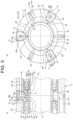
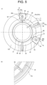
- the displacement detecting units 61 are arranged at those positions in the circumferential direction which at least avoid facing each other over the center axis in the small outer diameter portion 12a of the front cylindrical portion 12 of the housing 11, e.g., the displacement detecting units are formed at two locations with a distance of 120 degrees in the circumferential direction.
- the compressed gas is supplied to a lubrication system (lubrication line) of the pressure loss measuring unit 71 from the compressed gas supply unit 80 to carry out oil-air lubrication or oil-mist lubrication (not shown) for supplying a lubrication oil to the front rolling bearing set 31 and the rear rolling bearing 41.
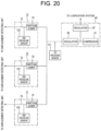
- the compressed gas supply unit 80 includes a compressor 81 for generating the compressed gas, a regulator 82 provided for the lubricant system for regulating the pressure of the compressed gas supplied from the compressor 81, and another regulator 83 connected in parallel with the regulator 82 and used for pressure loss measurement. It should be noted that the first embodiment is not limited to the oil-air lubrication or the oil-mist lubrication.
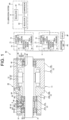
- the throttling of the throttling element 72 of the pressure loss measuring unit 71 is adjusted such that the differential pressure detection value detected by the differential pressure sensor 73 becomes the preset value while the rotary shaft 21 of the spindle apparatus 10 of the machine tool is rotating, with the radial direction displacement of the rotary shaft 21 being "0".
- the present invention is not limited to this adjustment.
- the differential pressure of each pressure loss measuring unit 71 may be adjusted to a certain value by the throttling element 72 of the pressure loss measuring unit 71 while the rotary shaft 21 of the spindle apparatus 10 is at rest without an external load (0 rotation state), and this state is set as displacement 0.
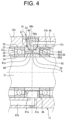
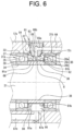
- the axial length of the measurement target gap g between the outer ring spacer 36 and the inner ring spacer 38, which is open to the compressed gas injection nozzle 62 is the required minimum axial length w, the influences of the viscosity of the compressed gas supplied to the measurement target gap g from the compressed gas injection nozzle 62 and the friction of the compressed gas supplied to the measurement target gap g are moderated.
- the time needed for the compressed gas to exit the bearing device is shortened. Therefore, it is possible to improve the responsiveness (speed of the response) to the radial direction displacement of the rotary shaft 21.
- the rise time (pressure rising speed) of the compressed gas at the high-pressure side of the differential pressure sensor 73 adjusted by the throttling element 77 is not necessarily exactly the same as the rise time of the compressed gas at the throttling element 72. It is satisfactory as long as the differential pressure between the high-pressure side and the low pressure side of the differential pressure sensor 73 falls within a predetermined range immediately after starting the supply of the compressed gas to the pressure loss measuring unit 71 from the regulator 83.
- the throttling element 77 is disposed in the pipe 75 that extends between the high-pressure side of the differential pressure sensor 73 and the regulator 83, and this prevents the differential pressure between the high-pressure side and the low-pressure side of the differential pressure sensor 73 from becoming excessively large, i.e., becoming larger than the standard value. It should be noted, however, that the present invention is not limited to the above-described configuration. As shown in FIG. 14 , the throttling element 77 of FIG. 13 may be omitted, and the relief valve 78 may be connected in parallel with the differential pressure sensor 73.
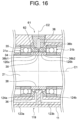
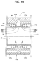
- the oil-air entering the air reservoirs 120a and 120b is depressurized in the air reservoirs 120a and 120b, respectively, and then flows in a gap between the portion 36b1 of the inner peripheral side ring portion 36b and the inner ring spacer 38 and a gap between the portion 36b2 of the inner peripheral side ring portion 36b and the inner ring spacer 38 such that the oil-air is supplied to the front rolling bearings 31 (31a, 31b).
Landscapes
- Engineering & Computer Science (AREA)
- General Engineering & Computer Science (AREA)
- Mechanical Engineering (AREA)
- Physics & Mathematics (AREA)
- General Physics & Mathematics (AREA)
- Rolling Contact Bearings (AREA)
- Magnetic Bearings And Hydrostatic Bearings (AREA)
- Force Measurement Appropriate To Specific Purposes (AREA)
- Turning (AREA)
Claims (24)
- Dispositif de palier prévu pour supporter un élément rotatif (21) sur un élément fixe (11) au moyen d'un roulement (31a, 31b) et comprenant une buse d'injection de gaz comprimé (62) prévue pour injecter du gaz comprimé dans un interstice (g) entre l'élément rotatif (21) et l'élément fixe (11) à proximité du roulement (31a, 31b),
caractérisé parune unité de mesure de déplacement (60) prévue pour mesurer un déplacement dans la direction radiale de l'élément rotatif (21) au moyen du gaz comprimé injecté dans l'interstice (g) à mesurer,ladite unité de mesure de déplacement (60) comprenant une pluralité de paires constituées d'une unité de détection de déplacement (61) et d'une unité de mesure de perte de pression (71), ainsi qu'une unité de traitement arithmétique (PU),la pluralité de paires de ladite unité de détection de déplacement (61) et de ladite unité de mesure de perte de pression (71) étant disposées dans la direction circonférentielle,l'unité de détection de déplacement (61) étant pourvue de la buse d'injection de gaz comprimé (62),l'unité de mesure de perte de pression (71) étant prévue pour mesurer une perte de pression du gaz comprimé refoulé vers l'unité de détection de déplacement (61),l'unité de traitement arithmétique (PU) étant prévue pour calculer le déplacement dans la direction radiale par conversion de la perte de pression mesurée en déplacement dans la direction radiale, oùchacune des unités de détection de déplacement (61) présente une rainure de récupération de gaz (81a, 81b) prévue pour récupérer le gaz comprimé injecté dans l'interstice (g) à mesurer par la buse d'injection de gaz comprimé (62), ladite rainure de récupération de gaz (81a, 81b) étant formée sur un côté ou sur les deux côtés par rapport à un axe (C2) de la buse d'injection de gaz comprimé (62), et oùl'unité de traitement arithmétique (PU) est prévue pour calculer une charge exercée sur l'élément rotatif (21) sur la base des résultats de mesure des unités de mesure de perte de pression (71). - Dispositif de palier selon la revendication 1, où
la pluralité de paires de ladite unité de détection de déplacement (61) et de ladite unité de mesure de perte de pression (71) sont disposées à différents emplacements dans la direction circonférentielle de l'élément rotatif (21), de sorte que les deux paires ne sont pas en vis-à-vis transversalement à un axe central (C1) de l'élément rotatif (21) . - Dispositif de palier selon la revendication 1, où
l'unité de mesure de déplacement (61) comprend trois paires ou plus de ladite unité de détection de déplacement (61) et de ladite unité de mesure de perte de pression (71) disposées à différents emplacements dans la direction circonférentielle de l'élément rotatif (21). - Dispositif de palier selon l'une des revendications 1 à 3, où
l'unité de détection de déplacement (61) comprend en outre un passage d'alimentation en gaz comprimé (64, 65) prévu pour alimenter en gaz comprimé la buse d'injection de gaz comprimé (62). - Dispositif de palier selon l'une des revendications 1 à 4, où
l'unité de détection de déplacement (61) comprend en outre une unité d'évacuation de gaz comprimé (87a, 87b) prévue pour évacuer le gaz comprimé récupéré dans la rainure de récupération de gaz à l'extérieur du dispositif de palier. - Dispositif de palier selon l'une des revendications 1 à 5, oùun anneau d'espacement extérieur (36) et un anneau d'espacement intérieur (38) sont disposés en contact avec le roulement (31a, 31b) entre l'élément rotatif (21) et l'élément fixe (11), etla buse d'injection de gaz comprimé (62) de l'unité de détection de déplacement (61) est formée dans l'anneau d'espacement extérieur (36), et l'interstice (g) à mesurer est formé entre l'anneau d'espacement extérieur (36) et l'anneau d'espacement intérieur (38).
- Dispositif de palier selon l'une des revendications 1 à 5, oùun anneau d'espacement extérieur (36) est disposé en contact avec le roulement (31a, 31b) entre l'élément rotatif et l'élément fixe (11), etla buse d'injection de gaz comprimé (62) de l'unité de détection de déplacement (61) est formée dans l'anneau d'espacement extérieur (36), et l'interstice (g) à mesurer est formé entre l'anneau d'espacement extérieur (36) et l'élément rotatif (21).
- Dispositif de palier selon la revendication 4, où une unité de conversion de direction du gaz (66) prévue pour convertir la direction du gaz comprimé est disposée entre la buse d'injection de gaz comprimé (62) et le passage d'alimentation en gaz comprimé (64, 65).
- Dispositif de palier selon la revendication 8, où l'unité de conversion de direction du gaz (66) comprend une partie de connexion de gaz (66) où est formé un passage de gaz (66a, 66b) prévu pour changer la direction du gaz comprimé.
- Dispositif de palier selon la revendication 8, où l'unité de conversion de direction du gaz (66) comprend un tube flexible (111) ayant des raccords de tube (112, 113) à ses deux extrémités.
- Dispositif de palier selon l'une des revendications 1 à 5, où
la buse d'injection de gaz comprimé (62) de l'unité de détection de déplacement (61) est formée à proximité du roulement (31a, 31b), et l'interstice (g) à mesurer est formé entre une surface périphérique intérieure de l'élément fixe (11) et une surface périphérique extérieure de l'élément rotatif (21) à proximité de la buse d'injection de gaz comprimé (62). - Dispositif de palier selon l'une des revendications 1 à 11, oùl'unité de mesure de perte de pression (71) comprend un élément d'étranglement (72) disposé sur un chemin d'alimentation en gaz comprimé (74) prévu pour refouler le gaz comprimé d'une unité d'alimentation en gaz comprimé (80) vers l'unité de détection de déplacement (61), etl'unité de mesure de perte de pression (71) mesure la perte de pression sur la base d'un différentiel de pression entre la pression du gaz comprimé entre l'élément d'étranglement (72) et l'unité de détection de déplacement (61) et la pression du gaz comprimé fourni par l'unité d'alimentation en gaz comprimé (80).
- Dispositif de palier selon la revendication 12, où
l'unité de mesure de perte de pression (71) comprend un capteur de différentiel de pression (73) prévu pour mesurer le différentiel de pression, et où un côté basse pression du capteur de différentiel de pression (73) est connecté entre l'élément d'étranglement (72) et l'unité de détection de déplacement (61), et un côté haute pression du capteur de différentiel de pression (73) est connecté à l'unité d'alimentation en gaz comprimé (80). - Dispositif de palier selon la revendication 13, où l'unité de mesure de perte de pression (71) comprend une soupape (78) disposée entre l'élément d'étranglement (72) et l'unité de détection de déplacement (61), et où la soupape est disposée à un emplacement plus proche de l'unité de détection de déplacement (61) qu'une partie de connexion à laquelle le côté basse pression du capteur de différentiel de pression (73) est connecté, et est prévue pour modérer une surcharge exercée sur le capteur de différentiel de pression (73) suite à une différence de temps de montée entre le côté haute pression et le côté basse pression.
- Dispositif de palier selon la revendication 13, où
un élément d'étranglement (77) prévu pour ajuster une montée en pression est prévu entre le côté haute pression du capteur de différentiel de pression (73) et l'unité d'alimentation en gaz comprimé (80). - Dispositif de palier selon la revendication 12, où l'unité de mesure de perte de pression (71) comprend un premier capteur de pression (121) prévu pour détecter la pression du gaz comprimé refoulé par l'unité d'alimentation en gaz comprimé (80) et un deuxième capteur de pression (122) prévu pour détecter la pression du gaz comprimé entre l'élément d'étranglement (72) et l'unité de détection de déplacement (61), et où l'unité de mesure de perte de pression (71) détecte le différentiel de pression en soustrayant une valeur de détection de pression du deuxième capteur de pression (122) d'une valeur de détection de pression du premier capteur de pression (121).
- Dispositif de palier selon l'une des revendications 12 à 16, où
l'unité de traitement arithmétique (PU) est prévue pour calculer une valeur de la charge exercée sur l'élément rotatif (21) sur la base du différentiel de pression détecté par l'unité de mesure de perte de pression (71). - Dispositif de palier selon la revendication 6 ou la revendication 7, comprenant en outreune unité d'alimentation en lubrifiant (123a, 123b) prévue pour alimenter le roulement (31a, 31b) en lubrifiant avec un deuxième gaz comprimé différent du gaz comprimé refoulé pour la mesure de déplacement,
oùau moins un renfoncement (120a, 120b) où circule le deuxième gaz comprimé est formé dans l'anneau d'espacement extérieur (36) entre la buse d'injection de gaz comprimé (62) et le roulement (31a, 31b). - Dispositif de palier selon la revendication 18, où
chacun desdits au moins un renfoncement (120a, 120b) est une partie de réduction de pression prévue pour réduire la pression du deuxième gaz comprimé. - Dispositif de palier selon la revendication 18 ou la revendication 19, où
chacun desdits au moins un renfoncement (120a, 120b) sert de rainure de récupération de gaz (81a, 81b). - Dispositif de palier selon l'une des revendications 18 à 20, où
l'unité d'alimentation en lubrifiant (123a, 123b) comporte une buse d'injection de lubrifiant (124a, 124b) débouchant sur ledit au moins un renfoncement (120a, 120b) formé dans l'anneau d'espacement extérieur (36) et injectant le lubrifiant avec le deuxième gaz comprimé dans ledit au moins un renfoncement (120a, 120b). - Dispositif de palier selon l'une des revendications 18 à 21, oùle dispositif de palier comprend une cavité (86) formée dans l'anneau d'espacement extérieur (36) et reliée à une partie d'évacuation de gaz comprimé (87a, 87b) prévue pour évacuer le gaz comprimé refoulé pour la mesure dedéplacement à l'extérieur du dispositif de palier, et où, lorsque ledit au moins un renfoncement comprend deux renfoncements (120a, 120b) formés de part et d'autre de la buse d'injection de gaz comprimé (62), la cavité communique avec au moins un des deux renfoncements (120a, 120b) formés de part et d'autre de la buse d'injection de gaz comprimé (62) .
- Dispositif de palier selon l'une des revendications 18 à 22, où
le roulement (31a, 31b) comprend une bague intérieure (34), une bague extérieure (33) et une pluralité d'éléments de roulement (35) disposés de manière rotative entre la bague intérieure (34) et la bague extérieure (33), et où la bague intérieure est de dimension (S) supérieure à la bague extérieure (33) dans une direction axiale de l'élément rotatif (21), et la bague intérieure (34) a une partie (34a) dont le diamètre s'accroît dans la direction des éléments de roulement (35). - Appareil à broche de machine-outil (10) comprenant un dispositif de palier selon l'une des revendications 1 à 23, où
l'appareil à broche de machine-outil (10) est prévu pour utiliser le dispositif de palier pour supporter de manière rotative un arbre principal (21) en tant qu'élément rotatif (21), et pour mesurer une charge exercée sur l'arbre principal (21).
Applications Claiming Priority (3)
| Application Number | Priority Date | Filing Date | Title |
|---|---|---|---|
| JP2018131256 | 2018-07-11 | ||
| PCT/JP2019/010373 WO2020012715A1 (fr) | 2018-07-11 | 2019-03-13 | Dispositif de paliers et appareil à broche de machine-outil |
| PCT/JP2019/027503 WO2020013276A1 (fr) | 2018-07-11 | 2019-07-11 | Dispositif de paliers et appareil à broche de machine-outil |
Publications (3)
| Publication Number | Publication Date |
|---|---|
| EP3786602A1 EP3786602A1 (fr) | 2021-03-03 |
| EP3786602A4 EP3786602A4 (fr) | 2022-01-05 |
| EP3786602B1 true EP3786602B1 (fr) | 2023-09-06 |
Family
ID=69143028
Family Applications (1)
| Application Number | Title | Priority Date | Filing Date |
|---|---|---|---|
| EP19834424.4A Active EP3786602B1 (fr) | 2018-07-11 | 2019-07-11 | Dispositif de paliers et appareil à broche de machine-outil |
Country Status (5)
| Country | Link |
|---|---|
| EP (1) | EP3786602B1 (fr) |
| JP (1) | JP6662499B1 (fr) |
| CN (1) | CN112384777B (fr) |
| TW (2) | TW202012801A (fr) |
| WO (2) | WO2020012715A1 (fr) |
Families Citing this family (6)
| Publication number | Priority date | Publication date | Assignee | Title |
|---|---|---|---|---|
| JP7543649B2 (ja) * | 2020-01-10 | 2024-09-03 | 日本精工株式会社 | 算出方法、軸受装置及び工作機械の主軸装置 |
| CN113281043B (zh) * | 2021-04-28 | 2023-06-06 | 重庆长江轴承股份有限公司 | 轴承动刚度测试装置 |
| KR102396577B1 (ko) * | 2021-10-01 | 2022-05-10 | 이지훈 | 워터젯 구동 스핀들 |
| CN114321188B (zh) * | 2021-12-29 | 2024-05-14 | 绍兴市肯特机械电子有限公司 | 一种低摩擦力矩轴承组及应用其的扭矩标准机 |
| JP7831228B2 (ja) | 2022-11-02 | 2026-03-17 | 日本精工株式会社 | 軸受装置 |
| TWI831691B (zh) * | 2023-05-08 | 2024-02-01 | 山衍機械有限公司 | 滑閥節流器及旋轉裝置 |
Family Cites Families (30)
| Publication number | Priority date | Publication date | Assignee | Title |
|---|---|---|---|---|
| DE2352788A1 (de) * | 1973-10-20 | 1975-04-30 | Zinser Textilmaschinen Gmbh | Luftgelagerter spinn- oder zwirnring fuer ringspinn- oder ringzwirnmaschinen |
| DE2356182A1 (de) * | 1973-11-09 | 1975-05-22 | Kraftwerk Union Ag | Kernreaktorbrennstab |
| JP3476164B2 (ja) * | 1995-04-18 | 2003-12-10 | 株式会社豊田自動織機 | 圧縮機における動力伝達構造 |
| JPH09329134A (ja) * | 1996-06-06 | 1997-12-22 | Mitsubishi Heavy Ind Ltd | 動圧気体軸受 |
| JP3662741B2 (ja) | 1997-04-28 | 2005-06-22 | Ntn株式会社 | 静圧磁気複合軸受 |
| JP3696398B2 (ja) * | 1997-04-28 | 2005-09-14 | Ntn株式会社 | 静圧磁気複合軸受およびスピンドル装置 |
| JP2000110836A (ja) * | 1998-10-06 | 2000-04-18 | Ntn Corp | 静圧軸受装置 |
| JP2002061750A (ja) * | 2000-08-24 | 2002-02-28 | Mitsutoyo Corp | 非接触シール装置 |
| JP4131312B2 (ja) * | 2000-10-27 | 2008-08-13 | 日本精工株式会社 | 軸受装置 |
| BR0210295B1 (pt) * | 2001-10-19 | 2011-08-09 | aparelho de mancal de fluido em uma máquina possuindo um pistão. | |
| CN2665395Y (zh) * | 2003-10-22 | 2004-12-22 | 何俊 | 气动马达 |
| KR100774009B1 (ko) * | 2005-10-14 | 2007-11-08 | 삼성전자주식회사 | 공기베어링용 강성실험장치 |
| JP2008082425A (ja) * | 2006-09-27 | 2008-04-10 | Ntn Corp | 磁気軸受装置 |
| JP2009061571A (ja) * | 2007-09-10 | 2009-03-26 | Ntn Corp | 工作機械主軸用スピンドル装置 |
| US8087907B2 (en) * | 2008-03-26 | 2012-01-03 | Ebara Corporation | Turbo vacuum pump |
| JP2010066150A (ja) * | 2008-09-11 | 2010-03-25 | Ntn Corp | 変位センサ |
| CN101408177A (zh) * | 2008-11-14 | 2009-04-15 | 浙江鸿友压缩机制造有限公司 | 一种旋转式压缩机的转子密封装置 |
| JP5564963B2 (ja) * | 2009-02-19 | 2014-08-06 | 日本精工株式会社 | 軸受装置及び工作機械の主軸装置 |
| CN202255341U (zh) * | 2011-09-22 | 2012-05-30 | 广州风神汽车有限公司 | 一种检测装置及具有该装置的压装系统 |
| JP5821781B2 (ja) * | 2012-05-29 | 2015-11-24 | 株式会社ジェイテクト | 転がり軸受装置 |
| DE202012102034U1 (de) * | 2012-06-04 | 2012-07-12 | Postberg + Co. Druckluft- Controlling Gmbh | Vorrichtung zur Differenzdruckmessung |
| JP5899056B2 (ja) * | 2012-06-08 | 2016-04-06 | 加藤 平三郎 | 転がり軸受 |
| CN202954972U (zh) * | 2012-08-07 | 2013-05-29 | 苏州英华特制冷设备技术有限公司 | 一种涡旋式压缩机的轴向密封机构 |
| CN103527560B (zh) * | 2013-10-18 | 2015-12-02 | 浙江工业大学 | 一种带气缸补偿的恒力输出气浮装置 |
| JP6209054B2 (ja) * | 2013-10-29 | 2017-10-04 | 株式会社日進製作所 | エアマイクロメータ |
| CN104279054B (zh) * | 2014-10-31 | 2017-05-17 | 刘振国 | 活塞转子发动机 |
| JP2016169946A (ja) * | 2015-03-11 | 2016-09-23 | 株式会社メトロール | 位置検出装置 |
| US10041534B2 (en) * | 2016-02-08 | 2018-08-07 | General Electric Company | Bearing outer race retention during high load events |
| JP6645378B2 (ja) * | 2016-08-03 | 2020-02-14 | 日本精工株式会社 | 玉軸受、及び工作機械用主軸装置 |
| CN207195180U (zh) * | 2017-09-19 | 2018-04-06 | 艾默生环境优化技术(苏州)有限公司 | 单向轴承组件、油刹车装置、涡旋压缩机 |
-
2019
- 2019-03-13 WO PCT/JP2019/010373 patent/WO2020012715A1/fr not_active Ceased
- 2019-05-23 TW TW108117864A patent/TW202012801A/zh unknown
- 2019-07-11 JP JP2019549490A patent/JP6662499B1/ja active Active
- 2019-07-11 TW TW108124467A patent/TWI814861B/zh active
- 2019-07-11 EP EP19834424.4A patent/EP3786602B1/fr active Active
- 2019-07-11 CN CN201980045690.3A patent/CN112384777B/zh active Active
- 2019-07-11 WO PCT/JP2019/027503 patent/WO2020013276A1/fr not_active Ceased
Also Published As
| Publication number | Publication date |
|---|---|
| TWI814861B (zh) | 2023-09-11 |
| CN112384777B (zh) | 2022-05-17 |
| WO2020013276A1 (fr) | 2020-01-16 |
| EP3786602A4 (fr) | 2022-01-05 |
| CN112384777A (zh) | 2021-02-19 |
| TW202012801A (zh) | 2020-04-01 |
| TW202012802A (zh) | 2020-04-01 |
| JP6662499B1 (ja) | 2020-03-11 |
| JPWO2020013276A1 (ja) | 2020-07-30 |
| WO2020012715A1 (fr) | 2020-01-16 |
| EP3786602A1 (fr) | 2021-03-03 |
Similar Documents
| Publication | Publication Date | Title |
|---|---|---|
| EP3786602A1 (fr) | Dispositif de paliers et appareil à broche de machine-outil | |
| JP4993688B2 (ja) | 主軸潤滑装置 | |
| JP5564963B2 (ja) | 軸受装置及び工作機械の主軸装置 | |
| JPS6158241B2 (fr) | ||
| US20080093175A1 (en) | Spindle device | |
| EP3822605B1 (fr) | Dispositif de paliers et appareil à broche de machine-outil | |
| EP4088839B1 (fr) | Procédé de calcul, dispositif de palier, et dispositif de broche pour machine-outil | |
| WO2022059573A1 (fr) | Dispositif de type palier | |
| JP2009138896A (ja) | 転がり軸受およびその潤滑方法 | |
| JPS6188015A (ja) | 予圧制御スピンドルユニツト | |
| EP4614126A1 (fr) | Dispositif de roulement et dispositif de broche | |
| KR20210141633A (ko) | 베어링 장치 | |
| GB2105416A (en) | Rolling bearing support | |
| US9194425B2 (en) | Device of the axial-directional oil chamber of hydrostatic spindle | |
| JP2005133891A (ja) | 軸受の予圧測定方法および予圧測定装置 | |
| EP4603715A1 (fr) | Dispositif de roulement et dispositif de fusée comportant un dispositif de roulement | |
| JP2024110470A (ja) | 軸受装置およびスピンドル装置 |
Legal Events
| Date | Code | Title | Description |
|---|---|---|---|
| STAA | Information on the status of an ep patent application or granted ep patent |
Free format text: STATUS: THE INTERNATIONAL PUBLICATION HAS BEEN MADE |
|
| PUAI | Public reference made under article 153(3) epc to a published international application that has entered the european phase |
Free format text: ORIGINAL CODE: 0009012 |
|
| STAA | Information on the status of an ep patent application or granted ep patent |
Free format text: STATUS: REQUEST FOR EXAMINATION WAS MADE |
|
| 17P | Request for examination filed |
Effective date: 20201116 |
|
| AK | Designated contracting states |
Kind code of ref document: A1 Designated state(s): AL AT BE BG CH CY CZ DE DK EE ES FI FR GB GR HR HU IE IS IT LI LT LU LV MC MK MT NL NO PL PT RO RS SE SI SK SM TR |
|
| AX | Request for extension of the european patent |
Extension state: BA ME |
|
| DAV | Request for validation of the european patent (deleted) | ||
| DAX | Request for extension of the european patent (deleted) | ||
| A4 | Supplementary search report drawn up and despatched |
Effective date: 20211203 |
|
| RIC1 | Information provided on ipc code assigned before grant |
Ipc: F16C 35/12 20060101ALI20211129BHEP Ipc: F16C 25/06 20060101ALI20211129BHEP Ipc: F16C 19/54 20060101ALI20211129BHEP Ipc: F16C 19/26 20060101ALI20211129BHEP Ipc: F16C 33/66 20060101ALI20211129BHEP Ipc: F16C 41/00 20060101ALI20211129BHEP Ipc: F16C 23/06 20060101ALI20211129BHEP Ipc: F16C 19/52 20060101ALI20211129BHEP Ipc: G01L 5/00 20060101AFI20211129BHEP |
|
| STAA | Information on the status of an ep patent application or granted ep patent |
Free format text: STATUS: EXAMINATION IS IN PROGRESS |
|
| 17Q | First examination report despatched |
Effective date: 20220809 |
|
| GRAP | Despatch of communication of intention to grant a patent |
Free format text: ORIGINAL CODE: EPIDOSNIGR1 |
|
| STAA | Information on the status of an ep patent application or granted ep patent |
Free format text: STATUS: GRANT OF PATENT IS INTENDED |
|
| INTG | Intention to grant announced |
Effective date: 20230616 |
|
| GRAS | Grant fee paid |
Free format text: ORIGINAL CODE: EPIDOSNIGR3 |
|
| GRAA | (expected) grant |
Free format text: ORIGINAL CODE: 0009210 |
|
| STAA | Information on the status of an ep patent application or granted ep patent |
Free format text: STATUS: THE PATENT HAS BEEN GRANTED |
|
| AK | Designated contracting states |
Kind code of ref document: B1 Designated state(s): AL AT BE BG CH CY CZ DE DK EE ES FI FR GB GR HR HU IE IS IT LI LT LU LV MC MK MT NL NO PL PT RO RS SE SI SK SM TR |
|
| REG | Reference to a national code |
Ref country code: GB Ref legal event code: FG4D |
|
| REG | Reference to a national code |
Ref country code: CH Ref legal event code: EP |
|
| REG | Reference to a national code |
Ref country code: DE Ref legal event code: R096 Ref document number: 602019037025 Country of ref document: DE |
|
| REG | Reference to a national code |
Ref country code: IE Ref legal event code: FG4D |
|
| REG | Reference to a national code |
Ref country code: LT Ref legal event code: MG9D |
|
| REG | Reference to a national code |
Ref country code: NL Ref legal event code: MP Effective date: 20230906 |
|
| PG25 | Lapsed in a contracting state [announced via postgrant information from national office to epo] |
Ref country code: GR Free format text: LAPSE BECAUSE OF FAILURE TO SUBMIT A TRANSLATION OF THE DESCRIPTION OR TO PAY THE FEE WITHIN THE PRESCRIBED TIME-LIMIT Effective date: 20231207 |
|
| PG25 | Lapsed in a contracting state [announced via postgrant information from national office to epo] |
Ref country code: SE Free format text: LAPSE BECAUSE OF FAILURE TO SUBMIT A TRANSLATION OF THE DESCRIPTION OR TO PAY THE FEE WITHIN THE PRESCRIBED TIME-LIMIT Effective date: 20230906 Ref country code: RS Free format text: LAPSE BECAUSE OF FAILURE TO SUBMIT A TRANSLATION OF THE DESCRIPTION OR TO PAY THE FEE WITHIN THE PRESCRIBED TIME-LIMIT Effective date: 20230906 Ref country code: NO Free format text: LAPSE BECAUSE OF FAILURE TO SUBMIT A TRANSLATION OF THE DESCRIPTION OR TO PAY THE FEE WITHIN THE PRESCRIBED TIME-LIMIT Effective date: 20231206 Ref country code: LV Free format text: LAPSE BECAUSE OF FAILURE TO SUBMIT A TRANSLATION OF THE DESCRIPTION OR TO PAY THE FEE WITHIN THE PRESCRIBED TIME-LIMIT Effective date: 20230906 Ref country code: LT Free format text: LAPSE BECAUSE OF FAILURE TO SUBMIT A TRANSLATION OF THE DESCRIPTION OR TO PAY THE FEE WITHIN THE PRESCRIBED TIME-LIMIT Effective date: 20230906 Ref country code: HR Free format text: LAPSE BECAUSE OF FAILURE TO SUBMIT A TRANSLATION OF THE DESCRIPTION OR TO PAY THE FEE WITHIN THE PRESCRIBED TIME-LIMIT Effective date: 20230906 Ref country code: GR Free format text: LAPSE BECAUSE OF FAILURE TO SUBMIT A TRANSLATION OF THE DESCRIPTION OR TO PAY THE FEE WITHIN THE PRESCRIBED TIME-LIMIT Effective date: 20231207 Ref country code: FI Free format text: LAPSE BECAUSE OF FAILURE TO SUBMIT A TRANSLATION OF THE DESCRIPTION OR TO PAY THE FEE WITHIN THE PRESCRIBED TIME-LIMIT Effective date: 20230906 |
|
| REG | Reference to a national code |
Ref country code: AT Ref legal event code: MK05 Ref document number: 1609123 Country of ref document: AT Kind code of ref document: T Effective date: 20230906 |
|
| PG25 | Lapsed in a contracting state [announced via postgrant information from national office to epo] |
Ref country code: NL Free format text: LAPSE BECAUSE OF FAILURE TO SUBMIT A TRANSLATION OF THE DESCRIPTION OR TO PAY THE FEE WITHIN THE PRESCRIBED TIME-LIMIT Effective date: 20230906 |
|
| PG25 | Lapsed in a contracting state [announced via postgrant information from national office to epo] |
Ref country code: IS Free format text: LAPSE BECAUSE OF FAILURE TO SUBMIT A TRANSLATION OF THE DESCRIPTION OR TO PAY THE FEE WITHIN THE PRESCRIBED TIME-LIMIT Effective date: 20240106 |
|
| PG25 | Lapsed in a contracting state [announced via postgrant information from national office to epo] |
Ref country code: AT Free format text: LAPSE BECAUSE OF FAILURE TO SUBMIT A TRANSLATION OF THE DESCRIPTION OR TO PAY THE FEE WITHIN THE PRESCRIBED TIME-LIMIT Effective date: 20230906 |
|
| PG25 | Lapsed in a contracting state [announced via postgrant information from national office to epo] |
Ref country code: ES Free format text: LAPSE BECAUSE OF FAILURE TO SUBMIT A TRANSLATION OF THE DESCRIPTION OR TO PAY THE FEE WITHIN THE PRESCRIBED TIME-LIMIT Effective date: 20230906 |
|
| PG25 | Lapsed in a contracting state [announced via postgrant information from national office to epo] |
Ref country code: SM Free format text: LAPSE BECAUSE OF FAILURE TO SUBMIT A TRANSLATION OF THE DESCRIPTION OR TO PAY THE FEE WITHIN THE PRESCRIBED TIME-LIMIT Effective date: 20230906 Ref country code: RO Free format text: LAPSE BECAUSE OF FAILURE TO SUBMIT A TRANSLATION OF THE DESCRIPTION OR TO PAY THE FEE WITHIN THE PRESCRIBED TIME-LIMIT Effective date: 20230906 Ref country code: IS Free format text: LAPSE BECAUSE OF FAILURE TO SUBMIT A TRANSLATION OF THE DESCRIPTION OR TO PAY THE FEE WITHIN THE PRESCRIBED TIME-LIMIT Effective date: 20240106 Ref country code: ES Free format text: LAPSE BECAUSE OF FAILURE TO SUBMIT A TRANSLATION OF THE DESCRIPTION OR TO PAY THE FEE WITHIN THE PRESCRIBED TIME-LIMIT Effective date: 20230906 Ref country code: EE Free format text: LAPSE BECAUSE OF FAILURE TO SUBMIT A TRANSLATION OF THE DESCRIPTION OR TO PAY THE FEE WITHIN THE PRESCRIBED TIME-LIMIT Effective date: 20230906 Ref country code: CZ Free format text: LAPSE BECAUSE OF FAILURE TO SUBMIT A TRANSLATION OF THE DESCRIPTION OR TO PAY THE FEE WITHIN THE PRESCRIBED TIME-LIMIT Effective date: 20230906 Ref country code: AT Free format text: LAPSE BECAUSE OF FAILURE TO SUBMIT A TRANSLATION OF THE DESCRIPTION OR TO PAY THE FEE WITHIN THE PRESCRIBED TIME-LIMIT Effective date: 20230906 Ref country code: PT Free format text: LAPSE BECAUSE OF FAILURE TO SUBMIT A TRANSLATION OF THE DESCRIPTION OR TO PAY THE FEE WITHIN THE PRESCRIBED TIME-LIMIT Effective date: 20240108 Ref country code: SK Free format text: LAPSE BECAUSE OF FAILURE TO SUBMIT A TRANSLATION OF THE DESCRIPTION OR TO PAY THE FEE WITHIN THE PRESCRIBED TIME-LIMIT Effective date: 20230906 |
|
| PG25 | Lapsed in a contracting state [announced via postgrant information from national office to epo] |
Ref country code: PL Free format text: LAPSE BECAUSE OF FAILURE TO SUBMIT A TRANSLATION OF THE DESCRIPTION OR TO PAY THE FEE WITHIN THE PRESCRIBED TIME-LIMIT Effective date: 20230906 |
|
| REG | Reference to a national code |
Ref country code: DE Ref legal event code: R097 Ref document number: 602019037025 Country of ref document: DE |
|
| PG25 | Lapsed in a contracting state [announced via postgrant information from national office to epo] |
Ref country code: DK Free format text: LAPSE BECAUSE OF FAILURE TO SUBMIT A TRANSLATION OF THE DESCRIPTION OR TO PAY THE FEE WITHIN THE PRESCRIBED TIME-LIMIT Effective date: 20230906 |
|
| PLBE | No opposition filed within time limit |
Free format text: ORIGINAL CODE: 0009261 |
|
| STAA | Information on the status of an ep patent application or granted ep patent |
Free format text: STATUS: NO OPPOSITION FILED WITHIN TIME LIMIT |
|
| PG25 | Lapsed in a contracting state [announced via postgrant information from national office to epo] |
Ref country code: DK Free format text: LAPSE BECAUSE OF FAILURE TO SUBMIT A TRANSLATION OF THE DESCRIPTION OR TO PAY THE FEE WITHIN THE PRESCRIBED TIME-LIMIT Effective date: 20230906 Ref country code: SI Free format text: LAPSE BECAUSE OF FAILURE TO SUBMIT A TRANSLATION OF THE DESCRIPTION OR TO PAY THE FEE WITHIN THE PRESCRIBED TIME-LIMIT Effective date: 20230906 |
|
| 26N | No opposition filed |
Effective date: 20240607 |
|
| PG25 | Lapsed in a contracting state [announced via postgrant information from national office to epo] |
Ref country code: BG Free format text: LAPSE BECAUSE OF FAILURE TO SUBMIT A TRANSLATION OF THE DESCRIPTION OR TO PAY THE FEE WITHIN THE PRESCRIBED TIME-LIMIT Effective date: 20230906 |
|
| PG25 | Lapsed in a contracting state [announced via postgrant information from national office to epo] |
Ref country code: BG Free format text: LAPSE BECAUSE OF FAILURE TO SUBMIT A TRANSLATION OF THE DESCRIPTION OR TO PAY THE FEE WITHIN THE PRESCRIBED TIME-LIMIT Effective date: 20230906 |
|
| PG25 | Lapsed in a contracting state [announced via postgrant information from national office to epo] |
Ref country code: MC Free format text: LAPSE BECAUSE OF FAILURE TO SUBMIT A TRANSLATION OF THE DESCRIPTION OR TO PAY THE FEE WITHIN THE PRESCRIBED TIME-LIMIT Effective date: 20230906 |
|
| PG25 | Lapsed in a contracting state [announced via postgrant information from national office to epo] |
Ref country code: LU Free format text: LAPSE BECAUSE OF NON-PAYMENT OF DUE FEES Effective date: 20240711 |
|
| GBPC | Gb: european patent ceased through non-payment of renewal fee |
Effective date: 20240711 |
|
| PG25 | Lapsed in a contracting state [announced via postgrant information from national office to epo] |
Ref country code: LU Free format text: LAPSE BECAUSE OF NON-PAYMENT OF DUE FEES Effective date: 20240711 |
|
| PG25 | Lapsed in a contracting state [announced via postgrant information from national office to epo] |
Ref country code: BE Free format text: LAPSE BECAUSE OF NON-PAYMENT OF DUE FEES Effective date: 20240731 |
|
| PG25 | Lapsed in a contracting state [announced via postgrant information from national office to epo] |
Ref country code: FR Free format text: LAPSE BECAUSE OF NON-PAYMENT OF DUE FEES Effective date: 20240731 |
|
| PG25 | Lapsed in a contracting state [announced via postgrant information from national office to epo] |
Ref country code: GB Free format text: LAPSE BECAUSE OF NON-PAYMENT OF DUE FEES Effective date: 20240711 |
|
| REG | Reference to a national code |
Ref country code: BE Ref legal event code: MM Effective date: 20240731 |
|
| PG25 | Lapsed in a contracting state [announced via postgrant information from national office to epo] |
Ref country code: IE Free format text: LAPSE BECAUSE OF NON-PAYMENT OF DUE FEES Effective date: 20240711 |
|
| PGFP | Annual fee paid to national office [announced via postgrant information from national office to epo] |
Ref country code: DE Payment date: 20250528 Year of fee payment: 7 |
|
| PGFP | Annual fee paid to national office [announced via postgrant information from national office to epo] |
Ref country code: IT Payment date: 20250623 Year of fee payment: 7 |
|
| PGFP | Annual fee paid to national office [announced via postgrant information from national office to epo] |
Ref country code: CH Payment date: 20250801 Year of fee payment: 7 |
|
| PG25 | Lapsed in a contracting state [announced via postgrant information from national office to epo] |
Ref country code: CY Free format text: LAPSE BECAUSE OF FAILURE TO SUBMIT A TRANSLATION OF THE DESCRIPTION OR TO PAY THE FEE WITHIN THE PRESCRIBED TIME-LIMIT; INVALID AB INITIO Effective date: 20190711 |
|
| PG25 | Lapsed in a contracting state [announced via postgrant information from national office to epo] |
Ref country code: HU Free format text: LAPSE BECAUSE OF FAILURE TO SUBMIT A TRANSLATION OF THE DESCRIPTION OR TO PAY THE FEE WITHIN THE PRESCRIBED TIME-LIMIT; INVALID AB INITIO Effective date: 20190711 |