EP3786603A1 - Surveillance d'une installation d'eau domestique - Google Patents
Surveillance d'une installation d'eau domestique Download PDFInfo
- Publication number
- EP3786603A1 EP3786603A1 EP20190825.8A EP20190825A EP3786603A1 EP 3786603 A1 EP3786603 A1 EP 3786603A1 EP 20190825 A EP20190825 A EP 20190825A EP 3786603 A1 EP3786603 A1 EP 3786603A1
- Authority
- EP
- European Patent Office
- Prior art keywords
- limit value
- water
- sensor
- control device
- electronic control
- Prior art date
- Legal status (The legal status is an assumption and is not a legal conclusion. Google has not performed a legal analysis and makes no representation as to the accuracy of the status listed.)
- Granted
Links
Images

Classifications
-
- G—PHYSICS
- G01—MEASURING; TESTING
- G01M—TESTING STATIC OR DYNAMIC BALANCE OF MACHINES OR STRUCTURES; TESTING OF STRUCTURES OR APPARATUS, NOT OTHERWISE PROVIDED FOR
- G01M3/00—Investigating fluid-tightness of structures
- G01M3/02—Investigating fluid-tightness of structures by using fluid or vacuum
- G01M3/26—Investigating fluid-tightness of structures by using fluid or vacuum by measuring rate of loss or gain of fluid, e.g. by pressure-responsive devices, by flow detectors
- G01M3/28—Investigating fluid-tightness of structures by using fluid or vacuum by measuring rate of loss or gain of fluid, e.g. by pressure-responsive devices, by flow detectors for pipes, cables or tubes; for pipe joints or seals; for valves ; for welds
- G01M3/2807—Investigating fluid-tightness of structures by using fluid or vacuum by measuring rate of loss or gain of fluid, e.g. by pressure-responsive devices, by flow detectors for pipes, cables or tubes; for pipe joints or seals; for valves ; for welds for pipes
Definitions
- Condition sensors are provided at the water outlets, which generally check whether a water outlet has been opened or not.
- reference [1] speaks of an - obviously fixedly predetermined - normal flow velocity, which is determined according to the description and claims according to a plausibility rule and assigned to the respectively detected actuation state, derived from the actuation state of the water consumer or based on the Consumption behavior of the water consumers going back from a water pressure to be measured determined depending on or calculated based on a flow model of the building's drinking water network and taught in a control system in a learning process.
- the necessary plausibility rule is only described in general in reference [1], however, concrete closing criteria are not mentioned.
- the value “zero” or an unspecified value of the detected flow rate is specified as a limit value - possibly in the sense of the first limit value GW1 defined at the outset. Accordingly, the detected flow velocity should only be classified as “plausible” if it “lies below a predetermined value or is zero”.
- the limit value does not necessarily have to be lower than the normal flow velocity.
- the normal flow rate is determined taking into account the actuation status of all water consumers - with and without a sensor. The actuation state of the water consumer without a sensor must also be derived or entered, which requires considerable effort.
- a method for monitoring a domestic water installation of the type mentioned which is characterized in that the first limit value GW1 is replaced by a variably predetermined second limit value GW2 stored in the electronic control device or retrievable by the electronic control device, if a sensor for detecting the state of a tap signals a water withdrawal, the following applies to the limit values: GW2> GW1, and that the second limit value GW2 is selected depending on the location of the sensor that signals water withdrawal.
- the present invention prescribes the first limit value GW1 in the electronic control device to save or from to have this queried. If a sensor for detecting the status of a tap signals a water withdrawal, the first limit value GW1 is always replaced by a second limit value GW2, which is not fixed but variable and which is also stored in the electronic control device or at least can be queried by it. However, the following must always apply: GW2> GW1, otherwise GW1 remains valid.
- tapping points that are equipped with a sensor are taken into account. All other water consumers are not taken into account.
- the second limit value GW2 is selected as a function of the location of use of the sensor, which signals that water has been withdrawn. If the sensor is located at a tap where larger water withdrawals are planned (e.g. garden irrigation, shower, water withdrawals for technical applications in industry ...), the limit value GW2 can be selected to be correspondingly high, while at tapping points with low water withdrawals (e.g. fittings on a hand wash basin) the limit value LV2 is selected correspondingly lower.
- the present invention always proposes an automatic change to a generous monitoring mode when it can be proven that water is being tapped. Then there is an automatic return to the stricter monitoring mode if no more water is being drawn from one of the sensor-monitored tapping points.
- Tapping points without a sensor are normally always automatically protected to a higher level above the stricter limit value GW1.
- the flow meter and the closure member in the central supply line do not necessarily have to be arranged in a common housing.
- the flow meter can be positioned in a central water softening system, while the closure element is installed separately in front of the water softener in the central supply line.
- Flow meters can be used as sensors.
- the sensors record, for example, the valve states " open” or “closed” at the relevant tapping point.
- the flow can be measured directly, for example by means of a turbine wheel flow meter, magnetic-inductive flow meter, ultrasonic flow meter and the like.
- the sensor can detect only an "on / on position" of the tap, such as via the actuation of a valve, a pressure change, a change in conductivity, a change in temperature or similar indicators.
- Sensors can be integrated in an aerator or be designed in some other way, for example as an intermediate piece. Likewise, sensors can be arranged externally directly on or at least in the vicinity of the tapping point.
- Sensors can be designed to be energy self-sufficient (energy supply by means of a turbine) or, for example, are supplied with a button cell.
- sensors can be designed with an optical status display (e.g. traffic light system for the water withdrawal time or the total amount of water withdrawn).
- optical status display e.g. traffic light system for the water withdrawal time or the total amount of water withdrawn.
- One class of particularly preferred embodiments of the water treatment system according to the invention is characterized in that the size of the second limit value GW2 can be freely selected within a predetermined value range. In this way, the circumstances in differently designed domestic water installations can then be individually addressed and correspondingly optimal values can be input into the electronic control device.
- the size of the second limit value GW2 is selected as a function of the instantaneous flow rate or the duration of an uninterrupted water withdrawal or the volume of water tapped without interruption.
- Embodiments of the method according to the invention in which the second limit value GW2 is time-dependent, in particular dependent on the local time, are also particularly preferred. At night or during the absence of people in the house (for example during vacation), the limit value GW2 can be lowered or completely suspended, so that the stricter first limit value GW1 applies. The first limit value GW1 itself can also be lowered in these phases.
- the second limit value GW2 is selected to be significantly greater than the first limit value GW1, in particular GW2 10 ⁇ GW1, preferably GW2 100 ⁇ GW1.
- the second limit value GW2 is set so high that it almost tends towards infinity. If a sensor for detecting the status of a tap now registers a water withdrawal, this measure stops the monitoring of the domestic water installation. This prevents a really wanted water withdrawal from being accidentally interrupted.
- the second limit value GW2 is adapted in accordance with a predefinable consumption profile of a tap with a sensor for this tap. For example, if there are frequent high water withdrawals at a tap, the limit value GW2 can be corrected upwards, in particular if the sensor signals a water withdrawal at this tap ("learning mode").
- the first limit value GW1 can also be adapted to a consumption profile.
- the second limit value LV2 corresponds to the largest value of the limit values LV2 single . This enabled safe monitoring despite - possibly even simultaneous - water withdrawal at several taps.
- the second limit value LV2 is the sum of the individual limits GW2. This sets a more generous monitoring mode with a less strict closing criterion. There is therefore only a small risk that the closure member closes and an intentional withdrawal of water is interrupted in the process.
- the second limit value LV2 is derived by means of a single mathematical function of the limits GW2, the single example, the individual limits GW2 and thus weights the individual tapping points different.
- the second limit value GW 2 may correspond to individual limit values to the mean of the GW2, or even single, the smallest value of the limit values set as limit value LV2 LV2.
- the withdrawal of water at these draw-off points is then not possible at all.
- the closure element in the central supply line closes.
- the refusal to withdraw water at a tap can be limited in time. For example, an outside fitting can be protected against unauthorized water extraction at night.
- Method variants are also advantageous which provide that when the first limit value GW1 is exceeded and / or when the second limit value GW2 is exceeded at a draw-off point with a sensor, the water withdrawal at this draw-off point is interrupted.
- the sensor at this tapping point is equipped with an actuator which interrupts the withdrawal of water at the tapping point when the first limit value GW1 is exceeded and / or when the second limit value GW2 is exceeded.
- the tap can be closed individually in this way. The water flow can be released again later, for example by a mechanical release.
- Another class of advantageous embodiments of the invention is characterized in that the second limit value GW2 for a tap is replaced by the first limit value GW1 when a sensor detects that the current state of the associated tap indicates no water withdrawal, or when the valve device of the tap closed is.
- a return is therefore made from the second limit value GW2 to the first limit value GW1 when the sensors detect that the draw-off points are closed or that water is no longer being drawn.
- a change to the first limit value GW1 can take place immediately, i.e. immediately in time, as soon as the sensors detect that the water withdrawal has ended.
- the sensors therefore send signals to the electronic control device at time intervals of duration ⁇ T when water is withdrawn from the associated tap and after a time t> ⁇ T without a signal, the second limit value GW2 for the corresponding tap is automatically replaced by the first limit value GW1 .
- a variant of this domestic water installation according to the invention is particularly preferred, which provides that at least one sensor of a tap is additionally equipped with an actuator which interrupts the water withdrawal at this tap when the first limit value GW1 is exceeded and / or the second limit value GW2 is exceeded at the tap .
- the present invention is concerned with the field of domestic water installations, in particular a water treatment system, and relates to a novel mode of operation and a corresponding configuration of such a domestic water installation with the aim of preventing or at least minimizing water damage from leakage events.
- the method according to the invention is distinguished from conventional methods according to the prior art in that the first limit value GW1 is specified by a second predetermined value that is stored in the electronic control device 7 or can be queried by the electronic control device 7 Limit value GW2 is replaced if a sensor 10a, 10b for detecting a state of a tap 8a, 8b signals a water withdrawal, with the following applies to the limit values: GW2> GW1.
- a domestic water installation 1 for carrying out the method according to the invention is distinguished from conventional arrangements according to the prior art in that the control device 7 is designed in such a way that the first limit value GW1 is stored in the electronic control device 7 or can be queried by the electronic control device 7 , prescribable second limit value GW2, if a sensor 10a, 10b for detecting a state of a tap 8a, 8b signals a water withdrawal, the following applies to the limit values: GW2> GW1.
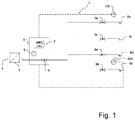
- such a domestic water installation according to the invention with monitoring, in which there is currently no water withdrawal can include a protective filter 3 in the flow direction downstream of the central water supply line 2, which protects the system from coarse contamination in the inflow.
- the indicated storage device for the limit values GW1 and GW1 in the electronic control device 7 can be interpreted as an essential part of a leakage protection device 4.
- valve devices 9a, 9b, 9c, 9d are closed at all tapping points 8a, 8b, 8c, 8d. Therefore, the stricter limit GW1 applies here.
- Fig. 2 shows the house installation 1 Fig. 1 in an operating situation in which water is withdrawn 11 at a tap 8c without a sensor .
- the lower first limit value GW1 also applies here and thus a stricter monitoring mode for the domestic water installation 1.
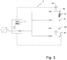
- FIG. 3 finally, house installation 1 shows off Fig. 1 in an operating situation in which water is drawn off 12 at a tap 8a with sensor 10a.
- the sensor 10a detects the water withdrawal 12 at the tap 8a, which is used, for example, for watering the garden or is used as a shower fitting. Since an already larger volume flow is regularly withdrawn here, that is to say in an intended manner, according to the invention the lower first limit value GW1 must be replaced by the higher, second limit value GW2. The monitoring mode defined by the second limit value GW2 is now less strict and takes into account that an intended water withdrawal is taking place.
Landscapes
- Physics & Mathematics (AREA)
- General Physics & Mathematics (AREA)
- Measuring Volume Flow (AREA)
- Water Treatment By Sorption (AREA)
- Investigating Or Analysing Materials By The Use Of Chemical Reactions (AREA)
Applications Claiming Priority (1)
| Application Number | Priority Date | Filing Date | Title |
|---|---|---|---|
| DE102019123268.6A DE102019123268A1 (de) | 2019-08-30 | 2019-08-30 | Überwachung einer Hauswasserinstallation |
Publications (3)
| Publication Number | Publication Date |
|---|---|
| EP3786603A1 true EP3786603A1 (fr) | 2021-03-03 |
| EP3786603C0 EP3786603C0 (fr) | 2023-07-05 |
| EP3786603B1 EP3786603B1 (fr) | 2023-07-05 |
Family
ID=72086704
Family Applications (1)
| Application Number | Title | Priority Date | Filing Date |
|---|---|---|---|
| EP20190825.8A Active EP3786603B1 (fr) | 2019-08-30 | 2020-08-13 | Surveillance d'une installation d'eau domestique |
Country Status (4)
| Country | Link |
|---|---|
| EP (1) | EP3786603B1 (fr) |
| DE (1) | DE102019123268A1 (fr) |
| ES (1) | ES2952566T3 (fr) |
| PL (1) | PL3786603T3 (fr) |
Cited By (1)
| Publication number | Priority date | Publication date | Assignee | Title |
|---|---|---|---|---|
| CN113774992A (zh) * | 2021-09-06 | 2021-12-10 | 中南水务工程有限公司 | 自来水供水管网结构及其施工方法 |
Families Citing this family (1)
| Publication number | Priority date | Publication date | Assignee | Title |
|---|---|---|---|---|
| DE102023121290A1 (de) | 2023-08-09 | 2025-02-13 | Judo Wasseraufbereitung Gmbh | Wasserschadenschutzvorrichtung mit Notentriegelung |
Citations (14)
| Publication number | Priority date | Publication date | Assignee | Title |
|---|---|---|---|---|
| EP0731313B1 (fr) | 1995-03-08 | 1998-11-25 | Judo Wasseraufbereitung GmbH | Dispositif de protection contre les dégats d'eau |
| DE19608527C2 (de) | 1996-03-06 | 1999-10-21 | Judo Wasseraufbereitung | Wasserschadenschutzvorrichtung |
| DE19835621C1 (de) | 1998-08-06 | 2000-01-27 | Flughafen Muenchen Gmbh | Überwachungssystem für ein Pipelinesystem |
| DE19944830A1 (de) | 1999-09-18 | 2001-03-29 | Falk Huhn | Sicherheitseinrichtung zum Absperren von Versorgungsleitungen für flüssige und gasförmige Medien, vorzugsweise für Hauswasserleitungen |
| US20020088491A1 (en) | 1998-06-23 | 2002-07-11 | Gennai Yanagisawa | Fluid leakage monitoring system |
| EP0794381B1 (fr) | 1996-03-06 | 2003-11-12 | Judo Wasseraufbereitung GmbH | Dispositif de protection contre les dégats d'eau |
| WO2006069930A2 (fr) | 2004-12-23 | 2006-07-06 | Endress+Hauser | Reseau de conduites a structure hierarchique pour l'alimentation en eau ou en gaz et/ou pour l'evacuation d'eau sanitaire, procede pour detecter une fuite dans un tel reseau de conduites et procede pour la determination assistee par ordinateur d'une duree de vie theoriquement restante d'une source d'energie renouvelable |
| US20080251131A1 (en) * | 2007-04-12 | 2008-10-16 | Michael Brent Ford | Method and system for detecting water system leaks |
| DE102012211132A1 (de) | 2012-06-28 | 2014-01-02 | Geze Gmbh | Vorrichtung und Verfahren zur Erkennung einer Undichtigkeit einer fluiddurchströmten Leitung |
| DE202015002251U1 (de) | 2015-03-24 | 2015-05-06 | Jörn Kirschner | Warnsystem zum frühzeitigen Erkennen von minimalen Schadstellen innerhalb eines Wasserleitungssystems und ein daraus entstehenden Wasserschaden |
| DE102011055642B4 (de) | 2011-11-23 | 2017-05-11 | Tobias Heckhausen | Verfahren und Vorrichtung zur Vermeidung von Schäden durch Leckagen in unter Druck stehenden offenen Strömungsrohren |
| DE102017005499A1 (de) * | 2017-06-09 | 2018-12-13 | Diehl Metering Gmbh | Verfahren zur Erkennung eines Fluidverlusts in einem Fluidversorgungsnetz |
| DE102017117652A1 (de) | 2017-08-03 | 2019-02-07 | Schell Gmbh & Co. Kg | Verfahren zur Erfassung einer Leckage in einem Gebäude-Trinkwassernetzwerk |
| WO2019052893A1 (fr) * | 2017-09-15 | 2019-03-21 | Grohe Ag | Procédé pour détecter une fuite dans une conduite de liquide et compteur d'eau comportant une commande pour mettre en œuvre le procédé |
Family Cites Families (1)
| Publication number | Priority date | Publication date | Assignee | Title |
|---|---|---|---|---|
| DE102017126400A1 (de) * | 2017-11-10 | 2019-05-16 | Grohe Ag | Verfahren und Vorrichtung zum Betrieb einer Sanitäreinrichtung |
-
2019
- 2019-08-30 DE DE102019123268.6A patent/DE102019123268A1/de not_active Withdrawn
-
2020
- 2020-08-13 EP EP20190825.8A patent/EP3786603B1/fr active Active
- 2020-08-13 ES ES20190825T patent/ES2952566T3/es active Active
- 2020-08-13 PL PL20190825.8T patent/PL3786603T3/pl unknown
Patent Citations (16)
| Publication number | Priority date | Publication date | Assignee | Title |
|---|---|---|---|---|
| EP0731313B1 (fr) | 1995-03-08 | 1998-11-25 | Judo Wasseraufbereitung GmbH | Dispositif de protection contre les dégats d'eau |
| DE19508114C2 (de) | 1995-03-08 | 1999-02-25 | Judo Wasseraufbereitung | Verfahren zum Betrieb einer Wasserschadenschutzvorrichtung |
| DE19608527C2 (de) | 1996-03-06 | 1999-10-21 | Judo Wasseraufbereitung | Wasserschadenschutzvorrichtung |
| EP0794381B1 (fr) | 1996-03-06 | 2003-11-12 | Judo Wasseraufbereitung GmbH | Dispositif de protection contre les dégats d'eau |
| US20020088491A1 (en) | 1998-06-23 | 2002-07-11 | Gennai Yanagisawa | Fluid leakage monitoring system |
| DE19835621C1 (de) | 1998-08-06 | 2000-01-27 | Flughafen Muenchen Gmbh | Überwachungssystem für ein Pipelinesystem |
| DE19944830A1 (de) | 1999-09-18 | 2001-03-29 | Falk Huhn | Sicherheitseinrichtung zum Absperren von Versorgungsleitungen für flüssige und gasförmige Medien, vorzugsweise für Hauswasserleitungen |
| WO2006069930A2 (fr) | 2004-12-23 | 2006-07-06 | Endress+Hauser | Reseau de conduites a structure hierarchique pour l'alimentation en eau ou en gaz et/ou pour l'evacuation d'eau sanitaire, procede pour detecter une fuite dans un tel reseau de conduites et procede pour la determination assistee par ordinateur d'une duree de vie theoriquement restante d'une source d'energie renouvelable |
| US20080251131A1 (en) * | 2007-04-12 | 2008-10-16 | Michael Brent Ford | Method and system for detecting water system leaks |
| DE102011055642B4 (de) | 2011-11-23 | 2017-05-11 | Tobias Heckhausen | Verfahren und Vorrichtung zur Vermeidung von Schäden durch Leckagen in unter Druck stehenden offenen Strömungsrohren |
| DE102012211132A1 (de) | 2012-06-28 | 2014-01-02 | Geze Gmbh | Vorrichtung und Verfahren zur Erkennung einer Undichtigkeit einer fluiddurchströmten Leitung |
| DE202015002251U1 (de) | 2015-03-24 | 2015-05-06 | Jörn Kirschner | Warnsystem zum frühzeitigen Erkennen von minimalen Schadstellen innerhalb eines Wasserleitungssystems und ein daraus entstehenden Wasserschaden |
| DE102017005499A1 (de) * | 2017-06-09 | 2018-12-13 | Diehl Metering Gmbh | Verfahren zur Erkennung eines Fluidverlusts in einem Fluidversorgungsnetz |
| DE102017117652A1 (de) | 2017-08-03 | 2019-02-07 | Schell Gmbh & Co. Kg | Verfahren zur Erfassung einer Leckage in einem Gebäude-Trinkwassernetzwerk |
| WO2019052893A1 (fr) * | 2017-09-15 | 2019-03-21 | Grohe Ag | Procédé pour détecter une fuite dans une conduite de liquide et compteur d'eau comportant une commande pour mettre en œuvre le procédé |
| DE102017121489A1 (de) | 2017-09-15 | 2019-03-21 | Grohe Ag | Verfahren zum Detektieren einer Leckage in einer Flüssigkeitsleitung sowie Wasserzähler mit einer Steuerung zur Durchführung des Verfahrens |
Cited By (1)
| Publication number | Priority date | Publication date | Assignee | Title |
|---|---|---|---|---|
| CN113774992A (zh) * | 2021-09-06 | 2021-12-10 | 中南水务工程有限公司 | 自来水供水管网结构及其施工方法 |
Also Published As
| Publication number | Publication date |
|---|---|
| EP3786603C0 (fr) | 2023-07-05 |
| EP3786603B1 (fr) | 2023-07-05 |
| DE102019123268A1 (de) | 2021-03-04 |
| ES2952566T3 (es) | 2023-11-02 |
| PL3786603T3 (pl) | 2023-11-20 |
Similar Documents
| Publication | Publication Date | Title |
|---|---|---|
| EP3690151B1 (fr) | Système d'eau potable et d'eau sanitaire et son procédé de rinçage | |
| EP2096214B1 (fr) | Dispositif d'alimentation en eau potable d'un bâtiment et dispositif de commande pour celui-ci | |
| WO2014029699A1 (fr) | Dispositif de protection contre les fuites | |
| EP3337931A1 (fr) | Dispositif, système et procédé de rinçage automatique au moyen d'une soupape multiple | |
| EP3786603B1 (fr) | Surveillance d'une installation d'eau domestique | |
| DE1961928B2 (de) | Vorrichtung zum Überwachen einer Rohrleitung auf Rohrbrüche | |
| WO2014040823A1 (fr) | Dispositif pour réaliser un rinçage hygiénique dans une installation hydraulique | |
| DE19706564A1 (de) | Leckwasser-Erfassungs- und Stopeinrichtung für den Haushalt | |
| EP2700756A1 (fr) | Dispositif pour la réalisation d'un rinçage hygiénique dans une installation d'eau et l'installation comprenant un tel dispositif | |
| EP3682217B1 (fr) | Procédé pour détecter une fuite dans une conduite de liquide et compteur d'eau comportant une commande pour mettre en oevre le procédé | |
| DE202013102154U1 (de) | Anordnung zur Durchführung einer Hygienespülung in einer Wasserinstallation | |
| EP3848690A1 (fr) | Dispositif de protection contre les dégâts des eaux, en particulier de détection de petites fuites | |
| EP2993271B1 (fr) | Dispositif de commande et système d'eau potable et/ou sanitaire ayant un tel dispositif de commande | |
| DE9313983U1 (de) | Konfiguration zur komplexen Steuerung sanitärer Anlagen | |
| DE202012012276U1 (de) | Vorrichtung zum Reinigen einer häuslichen Wasserleitung und/oder zur Aufrechterhaltung der Wasserqualität | |
| DE102018001314A1 (de) | Warmwassererzeuger | |
| EP2721376B1 (fr) | Procédé et dispositif pour l'évaluation de la consommation d'un milieu dans un système d'alimentation | |
| EP3666984B1 (fr) | Dispositif de rinçage et système d'eau potable et sanitaire doté d'un tel dispositif de rinçage | |
| EP4310474B1 (fr) | Protection contre les fuites pour la détection de fuites importantes et petites | |
| WO2018192953A1 (fr) | Installation d'extinction d'incendie, système d'extinction d'incendie comportant cette dernière, ainsi que procédé pour la détermination de la propagation d'un feu | |
| EP2885467B1 (fr) | Installation d'eau potable avec détection de fuite | |
| DE202012013037U1 (de) | Trinkwasserleitungsanlage | |
| DE19850588C1 (de) | Durchflußmengenbegrenzer | |
| DE102006036518A1 (de) | Verfahren und Vorrichtung zur Leckerkennung in einer Wasserinstallation | |
| DE102017128553A1 (de) | Verfahren zum Detektieren einer Leckage in einer Flüssigkeitsleitung sowie Wasserzähler mit einer Steuerung zur Durchführung des Verfahrens |
Legal Events
| Date | Code | Title | Description |
|---|---|---|---|
| PUAI | Public reference made under article 153(3) epc to a published international application that has entered the european phase |
Free format text: ORIGINAL CODE: 0009012 |
|
| STAA | Information on the status of an ep patent application or granted ep patent |
Free format text: STATUS: THE APPLICATION HAS BEEN PUBLISHED |
|
| AK | Designated contracting states |
Kind code of ref document: A1 Designated state(s): AL AT BE BG CH CY CZ DE DK EE ES FI FR GB GR HR HU IE IS IT LI LT LU LV MC MK MT NL NO PL PT RO RS SE SI SK SM TR |
|
| AX | Request for extension of the european patent |
Extension state: BA ME |
|
| STAA | Information on the status of an ep patent application or granted ep patent |
Free format text: STATUS: REQUEST FOR EXAMINATION WAS MADE |
|
| 17P | Request for examination filed |
Effective date: 20210305 |
|
| RBV | Designated contracting states (corrected) |
Designated state(s): AL AT BE BG CH CY CZ DE DK EE ES FI FR GB GR HR HU IE IS IT LI LT LU LV MC MK MT NL NO PL PT RO RS SE SI SK SM TR |
|
| GRAP | Despatch of communication of intention to grant a patent |
Free format text: ORIGINAL CODE: EPIDOSNIGR1 |
|
| RIC1 | Information provided on ipc code assigned before grant |
Ipc: G01M 3/28 20060101AFI20221223BHEP |
|
| STAA | Information on the status of an ep patent application or granted ep patent |
Free format text: STATUS: GRANT OF PATENT IS INTENDED |
|
| INTG | Intention to grant announced |
Effective date: 20230202 |
|
| GRAS | Grant fee paid |
Free format text: ORIGINAL CODE: EPIDOSNIGR3 |
|
| GRAA | (expected) grant |
Free format text: ORIGINAL CODE: 0009210 |
|
| STAA | Information on the status of an ep patent application or granted ep patent |
Free format text: STATUS: THE PATENT HAS BEEN GRANTED |
|
| AK | Designated contracting states |
Kind code of ref document: B1 Designated state(s): AL AT BE BG CH CY CZ DE DK EE ES FI FR GB GR HR HU IE IS IT LI LT LU LV MC MK MT NL NO PL PT RO RS SE SI SK SM TR |
|
| REG | Reference to a national code |
Ref country code: CH Ref legal event code: EP |
|
| REG | Reference to a national code |
Ref country code: AT Ref legal event code: REF Ref document number: 1585257 Country of ref document: AT Kind code of ref document: T Effective date: 20230715 |
|
| REG | Reference to a national code |
Ref country code: DE Ref legal event code: R096 Ref document number: 502020004015 Country of ref document: DE |
|
| REG | Reference to a national code |
Ref country code: IE Ref legal event code: FG4D Free format text: LANGUAGE OF EP DOCUMENT: GERMAN |
|
| U01 | Request for unitary effect filed |
Effective date: 20230707 |
|
| U07 | Unitary effect registered |
Designated state(s): AT BE BG DE DK EE FI FR IT LT LU LV MT NL PT SE SI Effective date: 20230719 |
|
| U20 | Renewal fee for the european patent with unitary effect paid |
Year of fee payment: 4 Effective date: 20230823 |
|
| REG | Reference to a national code |
Ref country code: LT Ref legal event code: MG9D |
|
| REG | Reference to a national code |
Ref country code: ES Ref legal event code: FG2A Ref document number: 2952566 Country of ref document: ES Kind code of ref document: T3 Effective date: 20231102 |
|
| PG25 | Lapsed in a contracting state [announced via postgrant information from national office to epo] |
Ref country code: GR Free format text: LAPSE BECAUSE OF FAILURE TO SUBMIT A TRANSLATION OF THE DESCRIPTION OR TO PAY THE FEE WITHIN THE PRESCRIBED TIME-LIMIT Effective date: 20231006 |
|
| PG25 | Lapsed in a contracting state [announced via postgrant information from national office to epo] |
Ref country code: IS Free format text: LAPSE BECAUSE OF FAILURE TO SUBMIT A TRANSLATION OF THE DESCRIPTION OR TO PAY THE FEE WITHIN THE PRESCRIBED TIME-LIMIT Effective date: 20231105 |
|
| PG25 | Lapsed in a contracting state [announced via postgrant information from national office to epo] |
Ref country code: RS Free format text: LAPSE BECAUSE OF FAILURE TO SUBMIT A TRANSLATION OF THE DESCRIPTION OR TO PAY THE FEE WITHIN THE PRESCRIBED TIME-LIMIT Effective date: 20230705 Ref country code: NO Free format text: LAPSE BECAUSE OF FAILURE TO SUBMIT A TRANSLATION OF THE DESCRIPTION OR TO PAY THE FEE WITHIN THE PRESCRIBED TIME-LIMIT Effective date: 20231005 Ref country code: IS Free format text: LAPSE BECAUSE OF FAILURE TO SUBMIT A TRANSLATION OF THE DESCRIPTION OR TO PAY THE FEE WITHIN THE PRESCRIBED TIME-LIMIT Effective date: 20231105 Ref country code: HR Free format text: LAPSE BECAUSE OF FAILURE TO SUBMIT A TRANSLATION OF THE DESCRIPTION OR TO PAY THE FEE WITHIN THE PRESCRIBED TIME-LIMIT Effective date: 20230705 Ref country code: GR Free format text: LAPSE BECAUSE OF FAILURE TO SUBMIT A TRANSLATION OF THE DESCRIPTION OR TO PAY THE FEE WITHIN THE PRESCRIBED TIME-LIMIT Effective date: 20231006 |
|
| REG | Reference to a national code |
Ref country code: DE Ref legal event code: R097 Ref document number: 502020004015 Country of ref document: DE |
|
| PG25 | Lapsed in a contracting state [announced via postgrant information from national office to epo] |
Ref country code: SM Free format text: LAPSE BECAUSE OF FAILURE TO SUBMIT A TRANSLATION OF THE DESCRIPTION OR TO PAY THE FEE WITHIN THE PRESCRIBED TIME-LIMIT Effective date: 20230705 Ref country code: RO Free format text: LAPSE BECAUSE OF FAILURE TO SUBMIT A TRANSLATION OF THE DESCRIPTION OR TO PAY THE FEE WITHIN THE PRESCRIBED TIME-LIMIT Effective date: 20230705 Ref country code: CZ Free format text: LAPSE BECAUSE OF FAILURE TO SUBMIT A TRANSLATION OF THE DESCRIPTION OR TO PAY THE FEE WITHIN THE PRESCRIBED TIME-LIMIT Effective date: 20230705 Ref country code: MC Free format text: LAPSE BECAUSE OF FAILURE TO SUBMIT A TRANSLATION OF THE DESCRIPTION OR TO PAY THE FEE WITHIN THE PRESCRIBED TIME-LIMIT Effective date: 20230705 Ref country code: SK Free format text: LAPSE BECAUSE OF FAILURE TO SUBMIT A TRANSLATION OF THE DESCRIPTION OR TO PAY THE FEE WITHIN THE PRESCRIBED TIME-LIMIT Effective date: 20230705 |
|
| PLBE | No opposition filed within time limit |
Free format text: ORIGINAL CODE: 0009261 |
|
| STAA | Information on the status of an ep patent application or granted ep patent |
Free format text: STATUS: NO OPPOSITION FILED WITHIN TIME LIMIT |
|
| REG | Reference to a national code |
Ref country code: IE Ref legal event code: MM4A |
|
| 26N | No opposition filed |
Effective date: 20240408 |
|
| PG25 | Lapsed in a contracting state [announced via postgrant information from national office to epo] |
Ref country code: IE Free format text: LAPSE BECAUSE OF NON-PAYMENT OF DUE FEES Effective date: 20230813 |
|
| PG25 | Lapsed in a contracting state [announced via postgrant information from national office to epo] |
Ref country code: IE Free format text: LAPSE BECAUSE OF NON-PAYMENT OF DUE FEES Effective date: 20230813 |
|
| U20 | Renewal fee for the european patent with unitary effect paid |
Year of fee payment: 5 Effective date: 20240827 |
|
| PGFP | Annual fee paid to national office [announced via postgrant information from national office to epo] |
Ref country code: PL Payment date: 20250527 Year of fee payment: 6 |
|
| PG25 | Lapsed in a contracting state [announced via postgrant information from national office to epo] |
Ref country code: CY Free format text: LAPSE BECAUSE OF FAILURE TO SUBMIT A TRANSLATION OF THE DESCRIPTION OR TO PAY THE FEE WITHIN THE PRESCRIBED TIME-LIMIT; INVALID AB INITIO Effective date: 20200813 |
|
| PG25 | Lapsed in a contracting state [announced via postgrant information from national office to epo] |
Ref country code: HU Free format text: LAPSE BECAUSE OF FAILURE TO SUBMIT A TRANSLATION OF THE DESCRIPTION OR TO PAY THE FEE WITHIN THE PRESCRIBED TIME-LIMIT; INVALID AB INITIO Effective date: 20200813 |
|
| U20 | Renewal fee for the european patent with unitary effect paid |
Year of fee payment: 6 Effective date: 20250825 |
|
| PGFP | Annual fee paid to national office [announced via postgrant information from national office to epo] |
Ref country code: ES Payment date: 20250917 Year of fee payment: 6 |
|
| PGFP | Annual fee paid to national office [announced via postgrant information from national office to epo] |
Ref country code: GB Payment date: 20250822 Year of fee payment: 6 |
|
| PGFP | Annual fee paid to national office [announced via postgrant information from national office to epo] |
Ref country code: CH Payment date: 20250901 Year of fee payment: 6 |
|
| PG25 | Lapsed in a contracting state [announced via postgrant information from national office to epo] |
Ref country code: TR Free format text: LAPSE BECAUSE OF FAILURE TO SUBMIT A TRANSLATION OF THE DESCRIPTION OR TO PAY THE FEE WITHIN THE PRESCRIBED TIME-LIMIT Effective date: 20230705 |