EP3786805A1 - Architecture de carte e/s basée sur un contrôleur commun - Google Patents
Architecture de carte e/s basée sur un contrôleur commun Download PDFInfo
- Publication number
- EP3786805A1 EP3786805A1 EP20164140.4A EP20164140A EP3786805A1 EP 3786805 A1 EP3786805 A1 EP 3786805A1 EP 20164140 A EP20164140 A EP 20164140A EP 3786805 A1 EP3786805 A1 EP 3786805A1
- Authority
- EP
- European Patent Office
- Prior art keywords
- card
- controller
- storage
- drive
- interface
- Prior art date
- Legal status (The legal status is an assumption and is not a legal conclusion. Google has not performed a legal analysis and makes no representation as to the accuracy of the status listed.)
- Granted
Links
Images

Classifications
-
- G—PHYSICS
- G06—COMPUTING OR CALCULATING; COUNTING
- G06F—ELECTRIC DIGITAL DATA PROCESSING
- G06F13/00—Interconnection of, or transfer of information or other signals between, memories, input/output devices or central processing units
- G06F13/38—Information transfer, e.g. on bus
- G06F13/40—Bus structure
- G06F13/4063—Device-to-bus coupling
- G06F13/4068—Electrical coupling
Definitions
- Network attached storage (NAS) devices may comprise a wide variety of bays for their storage devices.
- the NAS device typically requires more powerful processors and a different motherboard, redundant array of independent disks (RAID), and power and enclosure management architectures to support the different number of drives. This makes the hardware and software development and cost of the different NAS products difficult to manage.
- RAID redundant array of independent disks
- I2C port expanders which have limited addressing capabilities, to detect/control a fixed numbers of drives.
- I2C port expanders are only extensible by adding another port expander at another I2C address.
- These enclosure management topologies use all of the limited I2C addressing space and can only control a limited number of drives.
- the software and control system must be modified or configured differently to address the devices. This makes both hardware and software design more complicated and costly.
- I/O card for a storage device, such as a NAS.
- the I/O card may comprise an interface configured to enable the I/O card to be coupled to a motherboard of the storage device.
- the interface is extensible for multiple ranges of storage.
- a I/O card controller on the I/O card may be configured to identify the interface and determine one or more configurations of the backplane based on the identity of the interface.
- Another embodiment relates to a storage device that is extensible to multiple ranges of storage and that comprises an enclosure; a motherboard; an I/O card coupled to the motherboard and a set of drives coupled to the I/O card.
- the I/O card may be configured to interface with the motherboard over multiple ranges of storage based on a common architecture that can selectively address different numbers of storage devices.
- an I/O card comprising an interface configured to couple to a motherboard of a storage device; a I/O card controller configured to identify the interface and to determine the configuration of a set of modular interfaces provided in the backplane based on the identity of the interface.
- the modular interfaces may relate to power management, enclosure management (ECM) for the drives, LED status/activity, power control/sequencing, controllers for RAID, and switching between Serial Attached Small Computer Systems Interface (SAS) or Serial Advanced Technology Attachment (SATA) interfaces.
- SAS Serial Attached Small Computer Systems Interface
- SATA Serial Advanced Technology Attachment
- known storage devices such as NAS devices, may comprise multiple bays to accommodate a plurality of storage media.
- the embodiments relate to methods and systems that employ a common architecture that may be extended for different ranges of bays for a plurality of storage devices.
- the architecture comprises an extensible interface that may be adapted to a range of numbers of bays.
- the common architecture comprises a backplane architecture that employs serial registers and serial addressing rather than port expanders to connect to the bays.
- each backplane variant may have an identifier that has a format that indicates various characteristics of the backplane, such as its model type, number of interfaces, optional components, and the like.
- the identifier may comprise fields embedded within its format at specific locations that are recognizable by the motherboard. The motherboard may then select or map one or more configuration settings for its operations based on the identifier provided by the I/O card 104.
- the motherboard may thus recognize the I/O card (which may be configured as a riser card) and may configure other components to suit.
- the motherboard controller may be the same for all types of devices.
- the software executing on the motherboard controller may be the same or substantially the same, across configurations.
- auto-detection may be used by the motherboard controller to configure, for example, LED configuration, power sequencing, etc.
- the common architecture is flexible and can be employed with different form factors, such as rack-mounted form factors and pedestal form factors.
- the embodiments enable a common I/O card to be used for any type of motherboard controller, such as Intel's Xeon or Dual Xeon, for example.
- the design and maintenance of the device driver is also simplified because the application programming interface (API) remains relatively unchanged, regardless of the number of bays supported. In other words, the number of drives becomes just a parameter rather than a primary criterion.
- API application programming interface
- the disclosure relates to methods and systems for an I/O card that can be employed across different platforms.
- the I/O card may be configured to determine the personality of the system, such as enclosure management, related to temperature control, fault status to drives, drive presence detect, power sequencing, fan control, etc.
- the system control and storage management RAID
- the I/O card may be controlled as one personality on a single card. This feature simplifies the software design of the device since it eliminates or reduces the need for separate software development of the storage API and enclosure management API. Previously, these separate APIs required corresponding separate software development efforts, which led to delays and increased costs.
- the I/O card according to one embodiment enables, but does not require the integration of enclosure management and RAID management. For example, the embodiments enable customizing which drives are configured as boot drives and which drives are configured as data drives.
- embodiments are described herein in the context of rack-mounted NAS devices. However, the embodiments herein are applicable to any form factor, such as pedestal or desktop form factors. In addition, the embodiments may be applicable to different types of devices, such as servers, routers, etc. Furthermore, the embodiments may be readily deployed for extensibility for Just a Bunch of Ordinary Disks (JBODs) and RAIDBODs.
- JBODs Just a Bunch of Ordinary Disks
- RAIDBODs Just a Bunch of Ordinary Disks
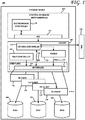
- a device 100 comprises a controller board (also denoted as motherboard) 102, an I/O card 104 (also denoted as extensible backplane herein), and a set of drives or storage devices 106.
- the set of drives 106 may be configured as RAID and the device 100 may be configured as a NAS.
- the same motherboard 102 and motherboard controller 108 may be used on NAS devices having different configurations and numbers of bays.
- the I/O card 104 may be configured for RAID control, power control and enclosure management duties, among other possible functions.
- the I/O card 104 may be physically configured as a riser card coupled to the motherboard 102 so that the motherboard/controller board 102 can accommodate different numbers of drives and different types of interfaces, such as SAS or SATA.
- the I/O card 104 may be a standalone card that is separate from, although coupled to, the motherboard 102.
- the enclosure management and/or other duties may be discharged by a separate, standalone card as well.
- the controller board 102 of device 100 may comprise a motherboard controller 108 coupled to an interface, such as a Peripheral Component Interconnect (PCI) interface or a PCI Express (PCIe) interface 110.
- the interface 110 may be coupled to an extensible backplane or I/O card 104.
- the I/O card 104 may comprise a I/O card controller 112 that may be configured to (among other functions) detect when a storage drive 106 is present on the interface 124 via, for example a serial peripheral interface (SPI) signal 118 and to turn on the power signals 120 to the storage drive 106 via a power controller 116.
- SPI serial peripheral interface
- the power controller 116 may be configured to supply both 5V and 12V, for example, to the drives 106 via, for example, a 16 pin drive power connector on the I/O card 104.
- the power controller 116 may be configured to provide other voltage levels.
- the I/O card 104 may be further configured to control a fan 126.
- the I/O card controller 112 may be coupled to a fan 126 and may be configured to communicate with the motherboard controller 108 via an interface to dynamically control the fan 126.
- the interface 124 may be configured, according to one embodiment, as an extensible drive interface configured to implement a serial addressing scheme to access the storage drives 106.
- the midplane 122 comprising the extensible drive interface 124 may comprise one or more shift registers to implement the serial addressing format.
- the midplane 122 may also be configured to comprise on-board SATA connectors configured to deliver power signals 120 and SATA signals 118 from the I/O card controller 112 and/or RAID controller 114.
- a 1U (rack unit) NAS may be implemented that comprises a common motherboard controller 108 and I/O card 104, which may be extended to, for example, 4 bays and 10 bays, as shown at 128 and 130.
- the architecture shown in Fig. 1 may implement a 2U NAS having a common controller board 102 and I/O card 104, which may be extended to 12 bays and 24 bays, as shown at 132 and 134, respectively.
- Other implementations and configurations are possible.
- the storage devices such as shown in Fig. 1 use a common architecture, which may be scaled from, for example, a 4 bay pedestal to 24 bay - 2U rack mount, the devices (although of different size) may employ the same software for drive power control, sequencing, RAID management, enclosure management, serial addressing, drive detection and/or LED control and the like.
- the motherboard controller 108 may be configured to perform an auto-detect of the I/O card 104 and determine the number of bays that have been configured.
- One embodiment comprises one or more shift registers and a serial addressing scheme to address the drives/bays coupled to the system.
- the serial addressing scheme allows the software to use same protocol for any number of devices.
- the addresses of the drives/bays may be streamed into the shift register(s) in a serial fashion.
- the shift registers may be, according to one implementation, two 74LV594A, which are 8-bit shift registers with output registers from Texas Instruments. The number of shift registers may be adjusted as needed.
- the addresses may be identifiable based on a framing sequence of bits, such as a fixed number of 0 or 1 bits, or some other reserved value known to the motherboard controller 108.
- Such software may be configured to identify the number of drives by reading a drive presence address as a sliding sequence of bits as they are output or otherwise read from the shift register(s).
- the motherboard controller 108 and software may utilize a common protocol to recognize virtually any number of devices and any address, since the addresses are serially-encoded.
- Such an addressing scheme and software design is not possible with I2C port expanders.
- this common architecture enables several changeable features with the same controller and software.
- Storage (drive) management e.g., RAID may now be configured as a changeable feature.
- Storage (drive) power management features such as power sequencing, hot swap control, etc.
- the same motherboard 102 and I/O card 104 may be configured to handle different numbers of drives 106 by swapping one midplane 122 for another midplane configured with a different number and/or type of connectors and interfaces.
- the serial addressing scheme and shift registers enable a common addressing scheme, irrespective of the number of bays and/or drives 106 provided.
- a microcontroller may now be used to control drive power enable (sequencing), drive fault and status LEDs, drive presence sense, fan RPM control, etc. For example, since the drive presence signal indicates the number of drives installed, the microcontroller may use this parameter to determine the number LEDs that need to be controlled, which allows a single microcontroller firmware set to be used across a multiple drive chassis.
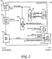
- Fig. 2 is a block diagram of one possible implementation of the midplane 122 of the device of Fig. 1 , according to one embodiment.
- the midplane does not comprise a I/O card controller or a RAID controller, as such functionality is embodied in the I/O card 104.
- the midplane 122 may comprise motherboard-side connectors configured to couple to mating connectors on the motherboard 102 and drive-side connectors configured to couple with mating connectors on the drives 106.
- Such connectors may be configured for power, data, drive indicators (e.g., LEDs) and/or for other purposes.
- the midplane 122 may comprise a Drive SPI connector (a 12 pin connector according to one implementation), configured to connect to LEDs (e.g., fault and status LEDs).
- a power connector 204 e.g., a 20 pin connector
- a data connector e.g., a mini-SAS connector in one implementation
- 206 may be provided and coupled to the I/O card controller 112 and/or the RAID controller 114 of Fig. 1 .
- a shift register 208 may be provided to receive drive presence detect signals from the drives.
- the midplane 122 is configured for four drives, numbered 0-3.
- An 8-bit shift register may indicate to the I/O card controller 112 which of the drives 106 has asserted the drive presence signal during, for example, initialization of the device.
- a shift register 210 may be provided, to drive LEDs 212 on the midplane 122, both to indicate a possible fault (e.g., red LEDs) as well as to indicate the status of the drives (e.g., blue LEDs).
- "Drive active" LEDs 214 e.g., white LEDs
- a drive-side full size data connector may be provided, as shown at 216.
- the connector 216 may be coupled to the motherboard-side connector 206, and may be configured to carry data, drive power signals, drive presence detect signals and drive active LED signals, for example.
- the connector 216 may be a 22 pin SAS connector.
- the midplane 122 shown in Fig. 2 may be readily adapted to other configurations, such as a 1U 10 bay configuration or a 2U 12 or 24 bay configurations, among other possibilities.
- the LEDs 212, 214 (or other indicators) may be powered on and enabled to show the activity, status and/or fault of each of the drives 106.
- the I/O card 122 may, as shown in Fig. 2 , comprise one or more on-board connectors 202 that are configured to deliver storage device activity, storage drive status and storage device fault signals to each storage drive 106 that is detected to be connected to the I/O card 122.
- the midplane 122 does not comprise any backplane or RAID controllers, as such are relegated to the I/O card 104.
- the midplane 122 may be modular, thereby enabling it to be swapped out when a different configuration (such as a 1U 9 bay implementation, for example) is desired.
- the midplane 122 therefore, may be swapped out at modest cost and without requiring software changes.
- the I/O card 104 comprising I/O, RAID, power management and ECM functionalities may be configured as a riser card configured to plug into the controller board (motherboard) 102.
- a riser card may be configured to provide additional connections to allow for additional bays to be added and controlled by the I/O card controller 112.
- the motherboard 102 may also be configured to supply additional expansion slots (for example, PCIe slots) that may be disposed in an orientation that is parallel to the controller board 102 to accommodate for the limited height available in a 1U rack.
- additional expansion slots for example, PCIe slots
- Modular components may be desirable in some embodiments because they are readily replaceable and may be configured to use less power, to be less costly, and to produce less heat.
- devices according to embodiments may employ, for example, modular power management; modular/extensible ECM for the drives, LED or other indicator status/activity, modular controllers for RAID; and switching between SAS or SATA interfaces.
- the I/O card controller 112 and the RAID controller 114 may be separate controllers, as shown in Fig. 1 .
- a suitable RAID controller may be obtained from, for example, Marvell Technology Group, Ltd.
- One such suitable RAID controller is Marvell's 88SE9480, a PCIe 2.0 x8 to 8 SAS/SATA 6 Gb/s ports RAID controller.
- Other RAID controllers may also be used.
- the RAID controller functions to offload many drive-related RAID functions from the I/O card controller 112.
- the RAID controller 114 may be configured to communicate with the motherboard 102 via, for example, an x8 PCIe interface.
- the I/O card controller is a TI MSP430 microcontroller from Texas Instruments, Inc.
- the I/O card controller may be configured to communicate with the motherboard 102 over a SMBus, for example.
- the functionality of the RAID controller 114 may be incorporated into the I/O card controller 112, or vice versa. In some non-RAID embodiments, a RAID controller 114 and/or the functionality thereof may not be provided. According to one embodiment, the I/O card controller 112 and/or the RAID controller 114 may be configured to manage the spin-up sequencing of the drives 106 upon startup thereof. For example, the I/O card controller 112 and/or the RAID controller 114 may be configured to stagger the spin-up of drives to limit the current draw by the drives 106 on startup to some predetermined limit.
- the extensible architecture presented according to one embodiment does not require new software, enclosure management services or power sequencing due to its modularity. This allows the use of a common software design for multiple products since the same addressing scheme is used for any number of drives.
- a RAID Option Read Only Memory may be initialized, whereupon the drives 106 may be detected by the I/O card controller 112 using drive presence signals and powered on. The boot drive(s) may then be identified and the operating system stored thereon may then be loaded. As part of the thermal ECM, the I/O card controller 112 may communicates with the motherboard controller 108 via, for example, a SMBus, to dynamically control the speed of the fan 126 to cool down the system as needed.
- Fig. 3 is a block diagram of a method according to one embodiment. Indeed, Fig. 3 shows a method of powering on a storage device.
- the storage device comprises a first controller on a motherboard, as shown at 108 in Fig. 1 , an I/O card 104 (also called I/O card herein) coupled to the motherboard 102, and a set of drives 106 coupled to the backplane 104.
- block B31 calls for initializing, on the I/O card 104, a second controller 112 in response to a power on request received from the first controller 108 on the motherboard 102.
- the second controller 112 on the I/O card 104 may detect which of the set of drives 106 is/are currently coupled to the I/O card. From the drives 106 detected to be currently coupled to the I/O card 104, a boot drive may be identified or determined, as called for by block B33. As shown at B34, the identified boot drive may then be powered on by the second controller 112. Thereafter, the other drives of the set of drives may be powered on (all at once or one or more sequentially in turn), based on a power signal 120 delivered from the I/O card 104.
- initializing the second controller in block B1 may include initializing a third controller configured as a controller for a redundant array of independent disks (RAID), such as shown at 114 in Fig. 1 .
- the second controller 112 may be configured to deliver power, along with power controller 116, to the other drives 106 based on a power enable signal 120 via a drive interface 124 on the I/O card 104.
- the interface 124 may include a SATA or SAS interface. Other configurations are possible.
- the first controller i.e., motherboard controller 108) may then issue one or more enclosure management commands that are received at the second controller 112.
- the second controller 112 may then execute the received enclosure management commands.
- Such enclosure management commands may comprise, for example, commands to dynamically control the fan or fans 126.
- the fan-controlling commands are executed, according to one embodiment, by the second controller (the I/O card controller 112 in Fig. 1 ), rather than by the motherboard controller 108.
- the active backplane or I/O card 104 may comprise both a RAID controller 114 and drive connectors (e.g., 22 pin SATA connectors).
- drive connectors e.g. 22 pin SATA connectors
- the RAID controller 114 may then drive both boot and data drives directly, without external power and data cables.
- the boot and data drives need not have the same form factor. In one implementation, for example, the boot drives have a 2.5" form factor, while the data drives may have a 3.5" for factor.
- the boot drive or drives may be configured, for example, as JBOD, RAID0 or RAID1 sets, while the data drives may be configured, for example, as RAID1, RAID5 or RAID6 sets. Other configurations are possible.
Landscapes
- Engineering & Computer Science (AREA)
- General Engineering & Computer Science (AREA)
- Theoretical Computer Science (AREA)
- Computer Hardware Design (AREA)
- Physics & Mathematics (AREA)
- General Physics & Mathematics (AREA)
- Power Sources (AREA)
Applications Claiming Priority (4)
| Application Number | Priority Date | Filing Date | Title |
|---|---|---|---|
| US201361866489P | 2013-08-15 | 2013-08-15 | |
| US14/150,615 US9582453B2 (en) | 2013-08-15 | 2014-01-08 | I/O card architecture based on a common controller |
| PCT/US2014/051370 WO2015023998A1 (fr) | 2013-08-15 | 2014-08-15 | Architecture de carte e/s fondée sur un contrôleur commun |
| EP14836837.6A EP3033685B1 (fr) | 2013-08-15 | 2014-08-15 | Architecture de carte e/s fondée sur un contrôleur commun |
Related Parent Applications (2)
| Application Number | Title | Priority Date | Filing Date |
|---|---|---|---|
| EP14836837.6A Division EP3033685B1 (fr) | 2013-08-15 | 2014-08-15 | Architecture de carte e/s fondée sur un contrôleur commun |
| EP14836837.6A Division-Into EP3033685B1 (fr) | 2013-08-15 | 2014-08-15 | Architecture de carte e/s fondée sur un contrôleur commun |
Publications (2)
| Publication Number | Publication Date |
|---|---|
| EP3786805A1 true EP3786805A1 (fr) | 2021-03-03 |
| EP3786805B1 EP3786805B1 (fr) | 2022-06-29 |
Family
ID=52467654
Family Applications (2)
| Application Number | Title | Priority Date | Filing Date |
|---|---|---|---|
| EP14836837.6A Active EP3033685B1 (fr) | 2013-08-15 | 2014-08-15 | Architecture de carte e/s fondée sur un contrôleur commun |
| EP20164140.4A Active EP3786805B1 (fr) | 2013-08-15 | 2014-08-15 | Architecture de carte e/s basée sur un contrôleur commun |
Family Applications Before (1)
| Application Number | Title | Priority Date | Filing Date |
|---|---|---|---|
| EP14836837.6A Active EP3033685B1 (fr) | 2013-08-15 | 2014-08-15 | Architecture de carte e/s fondée sur un contrôleur commun |
Country Status (5)
| Country | Link |
|---|---|
| US (1) | US9582453B2 (fr) |
| EP (2) | EP3033685B1 (fr) |
| CN (1) | CN105453064B (fr) |
| HK (1) | HK1220785A1 (fr) |
| WO (1) | WO2015023998A1 (fr) |
Families Citing this family (7)
| Publication number | Priority date | Publication date | Assignee | Title |
|---|---|---|---|---|
| US9436234B1 (en) * | 2013-09-30 | 2016-09-06 | Emc Corporation | Configurable system board |
| US11055252B1 (en) * | 2016-02-01 | 2021-07-06 | Amazon Technologies, Inc. | Modular hardware acceleration device |
| US10467172B2 (en) * | 2016-06-01 | 2019-11-05 | Seagate Technology Llc | Interconnect for shared control electronics |
| CN107515833B (zh) * | 2016-06-16 | 2021-03-16 | 伊姆西Ip控股有限责任公司 | 用于存储设备的输入输出卡以及存储设备 |
| US10452576B2 (en) | 2016-06-24 | 2019-10-22 | Avago Technologies International Sales Pte. Limited | NVMe drive detection from a SAS/SATA connector |
| CN109697179B (zh) * | 2017-10-24 | 2022-06-24 | 英业达科技有限公司 | 硬件资源扩充系统及热插入管理装置 |
| US10908940B1 (en) | 2018-02-26 | 2021-02-02 | Amazon Technologies, Inc. | Dynamically managed virtual server system |
Citations (2)
| Publication number | Priority date | Publication date | Assignee | Title |
|---|---|---|---|---|
| US20070192637A1 (en) * | 2006-02-10 | 2007-08-16 | Kubo Robert A | Apparatus and method to provide power to a plurality of data storage devices disposed in a data storage system |
| US7685329B1 (en) * | 2007-08-10 | 2010-03-23 | American Megatreads, Inc. | Detecting the presence and activity of a mass storage device |
Family Cites Families (40)
| Publication number | Priority date | Publication date | Assignee | Title |
|---|---|---|---|---|
| US5132635A (en) | 1991-03-05 | 1992-07-21 | Ast Research, Inc. | Serial testing of removable circuit boards on a backplane bus |
| JPH08185248A (ja) | 1994-12-15 | 1996-07-16 | Internatl Business Mach Corp <Ibm> | 電源管理機構、電源管理方法、及び入出力装置用コントローラ |
| US6098146A (en) | 1997-04-11 | 2000-08-01 | Dell Usa, L. P. | Intelligent backplane for collecting and reporting information in an SSA system |
| US20020052994A1 (en) | 1997-08-18 | 2002-05-02 | Liaqat Y. Khan | Section access for pc hard drive and the like |
| US6069293A (en) | 1998-11-05 | 2000-05-30 | De Somma; Carmine R. | Healing pack and applicator and method |
| US7271999B2 (en) | 1999-05-11 | 2007-09-18 | Josef Rabinovitz | Enclosure for computer peripheral devices |
| US6483107B1 (en) | 1999-05-11 | 2002-11-19 | Josef Rabinovitz | Canister having a combined guide rail and light pipe system for use in a computer peripheral enclosure |
| US7032119B2 (en) | 2000-09-27 | 2006-04-18 | Amphus, Inc. | Dynamic power and workload management for multi-server system |
| US6839788B2 (en) | 2001-09-28 | 2005-01-04 | Dot Hill Systems Corp. | Bus zoning in a channel independent storage controller architecture |
| US6856508B2 (en) | 2002-09-23 | 2005-02-15 | Josef Rabinovitz | Modular data storage device assembly |
| US7000037B2 (en) | 2002-10-24 | 2006-02-14 | Josef Rabinovitz | Large array of mass data storage devices connected to a computer by a serial link |
| US6957288B2 (en) | 2003-02-19 | 2005-10-18 | Dell Products L.P. | Embedded control and monitoring of hard disk drives in an information handling system |
| US20040199719A1 (en) | 2003-04-04 | 2004-10-07 | Network Appliance, Inc. | Standalone newtork storage system enclosure including head and multiple disk drives connected to a passive backplane |
| US7334064B2 (en) | 2003-04-23 | 2008-02-19 | Dot Hill Systems Corporation | Application server blade for embedded storage appliance |
| US7042717B2 (en) | 2003-09-12 | 2006-05-09 | Lsi Logic Corporation | Data storage system with a removable backplane having a array of disk drives |
| US7155546B2 (en) | 2003-12-18 | 2006-12-26 | Intel Corporation | Multiple physical interfaces in a slot of a storage enclosure to support different storage interconnect architectures |
| US7009872B2 (en) * | 2003-12-22 | 2006-03-07 | Hewlett-Packard Development Company, L.P. | MRAM storage device |
| US20060136644A1 (en) | 2004-12-20 | 2006-06-22 | Martin Cynthia L | SAS hot swap backplane expander module |
| US8301810B2 (en) | 2004-12-21 | 2012-10-30 | Infortrend Technology, Inc. | SAS storage virtualization controller, subsystem and system using the same, and method therefor |
| US7453707B2 (en) | 2005-07-28 | 2008-11-18 | Dell Products L.P. | Tool-less, translating hard drive bay |
| KR100803005B1 (ko) * | 2006-10-26 | 2008-02-14 | 삼성전자주식회사 | 메모리 인터페이싱 방법과 장치 |
| JP5386931B2 (ja) | 2007-11-15 | 2014-01-15 | 株式会社リコー | メモリカード制御装置およびメモリカード制御方法 |
| US7701705B1 (en) | 2007-12-10 | 2010-04-20 | Western Digital Technologies, Inc. | Information storage device with sheet metal projections and elastomeric inserts |
| US7979589B2 (en) | 2008-03-14 | 2011-07-12 | Silicon Image, Inc. | Method, apparatus, and system for port multiplier enhancement |
| US20090319713A1 (en) | 2008-06-24 | 2009-12-24 | Kwok-Yan Leung | Expansion card for external storage device |
| US8069293B1 (en) | 2009-05-22 | 2011-11-29 | Qlogic Corporation | Flexible server network connection upgrade systems and methods |
| US9377967B2 (en) | 2009-05-27 | 2016-06-28 | Dell Products L.P. | Systems and methods for scalable storage management |
| US8064194B2 (en) | 2009-06-16 | 2011-11-22 | Western Digital Technologies, Inc. | Mechanically decoupled status lens |
| US8113873B1 (en) | 2009-09-22 | 2012-02-14 | Western Digital Technologies, Inc. | Pivot assisted storage device unloading mechanism |
| US8358395B1 (en) | 2010-03-09 | 2013-01-22 | Western Digital Technologies, Inc. | Electronic display assembly comprising a display mount and a flex circuit wrapped around and adhered to the display mount |
| US8133426B1 (en) | 2010-05-28 | 2012-03-13 | Western Digital Technologies, Inc. | Injection molding with controlled part flexing |
| US8693208B2 (en) | 2010-08-06 | 2014-04-08 | Ocz Technology Group, Inc. | PCIe bus extension system, method and interfaces therefor |
| CN102375699A (zh) | 2010-08-23 | 2012-03-14 | 英业达股份有限公司 | 一种存储器系统 |
| US8417979B2 (en) | 2010-12-23 | 2013-04-09 | Western Digital Technologies, Inc. | Method and system for progressive power reduction of inactive device while maintaining ready status with host |
| US8583992B2 (en) | 2011-01-20 | 2013-11-12 | Taejin Info Tech Co., Ltd. | SAS-based semiconductor storage device memory disk unit |
| CN102841633A (zh) | 2011-06-23 | 2012-12-26 | 鸿富锦精密工业(深圳)有限公司 | 硬盘扩展装置及扩展模组 |
| US8498088B1 (en) | 2011-12-21 | 2013-07-30 | Western Digital Technologies, Inc. | Storage device with replaceable protection device |
| US8462460B1 (en) | 2012-03-29 | 2013-06-11 | Western Digital Technologies, Inc. | Shock mount and retainer for a disk drive enclosure |
| US8547658B1 (en) | 2012-10-18 | 2013-10-01 | Western Digital Technologies, Inc. | Data storage device enclosure enabling use of a common shock mount across different products |
| US20150006814A1 (en) * | 2013-06-28 | 2015-01-01 | Western Digital Technologies, Inc. | Dynamic raid controller power management |
-
2014
- 2014-01-08 US US14/150,615 patent/US9582453B2/en not_active Expired - Fee Related
- 2014-08-15 CN CN201480045235.0A patent/CN105453064B/zh active Active
- 2014-08-15 EP EP14836837.6A patent/EP3033685B1/fr active Active
- 2014-08-15 EP EP20164140.4A patent/EP3786805B1/fr active Active
- 2014-08-15 HK HK16108765.8A patent/HK1220785A1/zh unknown
- 2014-08-15 WO PCT/US2014/051370 patent/WO2015023998A1/fr not_active Ceased
Patent Citations (2)
| Publication number | Priority date | Publication date | Assignee | Title |
|---|---|---|---|---|
| US20070192637A1 (en) * | 2006-02-10 | 2007-08-16 | Kubo Robert A | Apparatus and method to provide power to a plurality of data storage devices disposed in a data storage system |
| US7685329B1 (en) * | 2007-08-10 | 2010-03-23 | American Megatreads, Inc. | Detecting the presence and activity of a mass storage device |
Also Published As
| Publication number | Publication date |
|---|---|
| US9582453B2 (en) | 2017-02-28 |
| EP3786805B1 (fr) | 2022-06-29 |
| HK1220785A1 (zh) | 2017-05-12 |
| CN105453064A (zh) | 2016-03-30 |
| EP3033685A4 (fr) | 2017-04-05 |
| EP3033685B1 (fr) | 2020-04-29 |
| WO2015023998A1 (fr) | 2015-02-19 |
| EP3033685A1 (fr) | 2016-06-22 |
| CN105453064B (zh) | 2019-04-05 |
| US20150052275A1 (en) | 2015-02-19 |
Similar Documents
| Publication | Publication Date | Title |
|---|---|---|
| EP3786805B1 (fr) | Architecture de carte e/s basée sur un contrôleur commun | |
| US10162786B2 (en) | Storage node based on PCI express interface | |
| US10452576B2 (en) | NVMe drive detection from a SAS/SATA connector | |
| US20070094472A1 (en) | Method for persistent mapping of disk drive identifiers to server connection slots | |
| JP2015084222A (ja) | サーバシステム及びストレージシステム | |
| US20140359189A1 (en) | Systems and methods for providing connections to an information handling system | |
| JP2009271637A (ja) | ストレージ装置及びそのドライブ起動方法 | |
| US7487372B2 (en) | Remote power sensing for hard disk bridge controller | |
| US8661237B2 (en) | System and method for booting a plurality of servers from a shared boot image stored on a USB boot image sharer | |
| US10853211B2 (en) | System and method for chassis-based virtual storage drive configuration | |
| US10282291B2 (en) | Storage system with data management mechanism and method of operation thereof | |
| CN120256373A (zh) | 设备控制装置、方法、存储介质及电子设备 | |
| CN113190084B (zh) | 一种支持多种位宽硬盘的硬盘背板连接方法及装置 | |
| US20140059370A1 (en) | Wake-on-local-area-network operations in a modular chassis using a virtualized input-output-virtualization environment | |
| US8554974B2 (en) | Expanding functionality of one or more hard drive bays in a computing system | |
| US20180157612A1 (en) | Server | |
| US7051134B2 (en) | Daisy chained ATA host controllers in a single PCI device | |
| US20060168358A1 (en) | Storage control system | |
| US7650447B2 (en) | System and method for a host to access an internal SATA storage device within an accessible host using an external serial ATA connection | |
| TWI252407B (en) | Method, apparatus system and machine readable medium for handling data transfers | |
| US20160353603A1 (en) | Interchangeable modules for cable management | |
| CN110941392A (zh) | 将远程存储设备模拟为本地存储设备的方法和装置 | |
| US9423863B2 (en) | Server system with power distribution board and storage control method thereof | |
| US10180926B2 (en) | Controlling data storage devices across multiple servers | |
| KR20150008828A (ko) | 디바이스 확장 기능을 갖는 확장형 멀티 디바이스 베이 시스템 |
Legal Events
| Date | Code | Title | Description |
|---|---|---|---|
| PUAI | Public reference made under article 153(3) epc to a published international application that has entered the european phase |
Free format text: ORIGINAL CODE: 0009012 |
|
| STAA | Information on the status of an ep patent application or granted ep patent |
Free format text: STATUS: REQUEST FOR EXAMINATION WAS MADE |
|
| 17P | Request for examination filed |
Effective date: 20200319 |
|
| AC | Divisional application: reference to earlier application |
Ref document number: 3033685 Country of ref document: EP Kind code of ref document: P |
|
| AK | Designated contracting states |
Kind code of ref document: A1 Designated state(s): AL AT BE BG CH CY CZ DE DK EE ES FI FR GB GR HR HU IE IS IT LI LT LU LV MC MK MT NL NO PL PT RO RS SE SI SK SM TR |
|
| GRAP | Despatch of communication of intention to grant a patent |
Free format text: ORIGINAL CODE: EPIDOSNIGR1 |
|
| STAA | Information on the status of an ep patent application or granted ep patent |
Free format text: STATUS: GRANT OF PATENT IS INTENDED |
|
| INTG | Intention to grant announced |
Effective date: 20220330 |
|
| GRAS | Grant fee paid |
Free format text: ORIGINAL CODE: EPIDOSNIGR3 |
|
| GRAA | (expected) grant |
Free format text: ORIGINAL CODE: 0009210 |
|
| STAA | Information on the status of an ep patent application or granted ep patent |
Free format text: STATUS: THE PATENT HAS BEEN GRANTED |
|
| AC | Divisional application: reference to earlier application |
Ref document number: 3033685 Country of ref document: EP Kind code of ref document: P |
|
| AK | Designated contracting states |
Kind code of ref document: B1 Designated state(s): AL AT BE BG CH CY CZ DE DK EE ES FI FR GB GR HR HU IE IS IT LI LT LU LV MC MK MT NL NO PL PT RO RS SE SI SK SM TR |
|
| RAP3 | Party data changed (applicant data changed or rights of an application transferred) |
Owner name: WESTERN DIGITAL TECHNOLOGIES, INC. |
|
| REG | Reference to a national code |
Ref country code: CH Ref legal event code: EP |
|
| REG | Reference to a national code |
Ref country code: DE Ref legal event code: R096 Ref document number: 602014084203 Country of ref document: DE |
|
| REG | Reference to a national code |
Ref country code: AT Ref legal event code: REF Ref document number: 1501801 Country of ref document: AT Kind code of ref document: T Effective date: 20220715 |
|
| REG | Reference to a national code |
Ref country code: IE Ref legal event code: FG4D |
|
| REG | Reference to a national code |
Ref country code: LT Ref legal event code: MG9D |
|
| PG25 | Lapsed in a contracting state [announced via postgrant information from national office to epo] |
Ref country code: SE Free format text: LAPSE BECAUSE OF FAILURE TO SUBMIT A TRANSLATION OF THE DESCRIPTION OR TO PAY THE FEE WITHIN THE PRESCRIBED TIME-LIMIT Effective date: 20220629 Ref country code: NO Free format text: LAPSE BECAUSE OF FAILURE TO SUBMIT A TRANSLATION OF THE DESCRIPTION OR TO PAY THE FEE WITHIN THE PRESCRIBED TIME-LIMIT Effective date: 20220929 Ref country code: LT Free format text: LAPSE BECAUSE OF FAILURE TO SUBMIT A TRANSLATION OF THE DESCRIPTION OR TO PAY THE FEE WITHIN THE PRESCRIBED TIME-LIMIT Effective date: 20220629 Ref country code: HR Free format text: LAPSE BECAUSE OF FAILURE TO SUBMIT A TRANSLATION OF THE DESCRIPTION OR TO PAY THE FEE WITHIN THE PRESCRIBED TIME-LIMIT Effective date: 20220629 Ref country code: GR Free format text: LAPSE BECAUSE OF FAILURE TO SUBMIT A TRANSLATION OF THE DESCRIPTION OR TO PAY THE FEE WITHIN THE PRESCRIBED TIME-LIMIT Effective date: 20220930 Ref country code: FI Free format text: LAPSE BECAUSE OF FAILURE TO SUBMIT A TRANSLATION OF THE DESCRIPTION OR TO PAY THE FEE WITHIN THE PRESCRIBED TIME-LIMIT Effective date: 20220629 Ref country code: BG Free format text: LAPSE BECAUSE OF FAILURE TO SUBMIT A TRANSLATION OF THE DESCRIPTION OR TO PAY THE FEE WITHIN THE PRESCRIBED TIME-LIMIT Effective date: 20220929 |
|
| REG | Reference to a national code |
Ref country code: NL Ref legal event code: MP Effective date: 20220629 |
|
| REG | Reference to a national code |
Ref country code: AT Ref legal event code: MK05 Ref document number: 1501801 Country of ref document: AT Kind code of ref document: T Effective date: 20220629 |
|
| PG25 | Lapsed in a contracting state [announced via postgrant information from national office to epo] |
Ref country code: RS Free format text: LAPSE BECAUSE OF FAILURE TO SUBMIT A TRANSLATION OF THE DESCRIPTION OR TO PAY THE FEE WITHIN THE PRESCRIBED TIME-LIMIT Effective date: 20220629 Ref country code: LV Free format text: LAPSE BECAUSE OF FAILURE TO SUBMIT A TRANSLATION OF THE DESCRIPTION OR TO PAY THE FEE WITHIN THE PRESCRIBED TIME-LIMIT Effective date: 20220629 |
|
| PG25 | Lapsed in a contracting state [announced via postgrant information from national office to epo] |
Ref country code: NL Free format text: LAPSE BECAUSE OF FAILURE TO SUBMIT A TRANSLATION OF THE DESCRIPTION OR TO PAY THE FEE WITHIN THE PRESCRIBED TIME-LIMIT Effective date: 20220629 |
|
| PG25 | Lapsed in a contracting state [announced via postgrant information from national office to epo] |
Ref country code: SM Free format text: LAPSE BECAUSE OF FAILURE TO SUBMIT A TRANSLATION OF THE DESCRIPTION OR TO PAY THE FEE WITHIN THE PRESCRIBED TIME-LIMIT Effective date: 20220629 Ref country code: SK Free format text: LAPSE BECAUSE OF FAILURE TO SUBMIT A TRANSLATION OF THE DESCRIPTION OR TO PAY THE FEE WITHIN THE PRESCRIBED TIME-LIMIT Effective date: 20220629 Ref country code: RO Free format text: LAPSE BECAUSE OF FAILURE TO SUBMIT A TRANSLATION OF THE DESCRIPTION OR TO PAY THE FEE WITHIN THE PRESCRIBED TIME-LIMIT Effective date: 20220629 Ref country code: PT Free format text: LAPSE BECAUSE OF FAILURE TO SUBMIT A TRANSLATION OF THE DESCRIPTION OR TO PAY THE FEE WITHIN THE PRESCRIBED TIME-LIMIT Effective date: 20221031 Ref country code: ES Free format text: LAPSE BECAUSE OF FAILURE TO SUBMIT A TRANSLATION OF THE DESCRIPTION OR TO PAY THE FEE WITHIN THE PRESCRIBED TIME-LIMIT Effective date: 20220629 Ref country code: EE Free format text: LAPSE BECAUSE OF FAILURE TO SUBMIT A TRANSLATION OF THE DESCRIPTION OR TO PAY THE FEE WITHIN THE PRESCRIBED TIME-LIMIT Effective date: 20220629 Ref country code: AT Free format text: LAPSE BECAUSE OF FAILURE TO SUBMIT A TRANSLATION OF THE DESCRIPTION OR TO PAY THE FEE WITHIN THE PRESCRIBED TIME-LIMIT Effective date: 20220629 |
|
| PG25 | Lapsed in a contracting state [announced via postgrant information from national office to epo] |
Ref country code: PL Free format text: LAPSE BECAUSE OF FAILURE TO SUBMIT A TRANSLATION OF THE DESCRIPTION OR TO PAY THE FEE WITHIN THE PRESCRIBED TIME-LIMIT Effective date: 20220629 Ref country code: IS Free format text: LAPSE BECAUSE OF FAILURE TO SUBMIT A TRANSLATION OF THE DESCRIPTION OR TO PAY THE FEE WITHIN THE PRESCRIBED TIME-LIMIT Effective date: 20221029 |
|
| REG | Reference to a national code |
Ref country code: DE Ref legal event code: R097 Ref document number: 602014084203 Country of ref document: DE |
|
| PG25 | Lapsed in a contracting state [announced via postgrant information from national office to epo] |
Ref country code: MC Free format text: LAPSE BECAUSE OF FAILURE TO SUBMIT A TRANSLATION OF THE DESCRIPTION OR TO PAY THE FEE WITHIN THE PRESCRIBED TIME-LIMIT Effective date: 20220629 Ref country code: AL Free format text: LAPSE BECAUSE OF FAILURE TO SUBMIT A TRANSLATION OF THE DESCRIPTION OR TO PAY THE FEE WITHIN THE PRESCRIBED TIME-LIMIT Effective date: 20220629 |
|
| REG | Reference to a national code |
Ref country code: CH Ref legal event code: PL |
|
| PG25 | Lapsed in a contracting state [announced via postgrant information from national office to epo] |
Ref country code: LU Free format text: LAPSE BECAUSE OF NON-PAYMENT OF DUE FEES Effective date: 20220815 Ref country code: LI Free format text: LAPSE BECAUSE OF NON-PAYMENT OF DUE FEES Effective date: 20220831 Ref country code: DK Free format text: LAPSE BECAUSE OF FAILURE TO SUBMIT A TRANSLATION OF THE DESCRIPTION OR TO PAY THE FEE WITHIN THE PRESCRIBED TIME-LIMIT Effective date: 20220629 Ref country code: CZ Free format text: LAPSE BECAUSE OF FAILURE TO SUBMIT A TRANSLATION OF THE DESCRIPTION OR TO PAY THE FEE WITHIN THE PRESCRIBED TIME-LIMIT Effective date: 20220629 Ref country code: CH Free format text: LAPSE BECAUSE OF NON-PAYMENT OF DUE FEES Effective date: 20220831 |
|
| REG | Reference to a national code |
Ref country code: BE Ref legal event code: MM Effective date: 20220831 |
|
| PLBE | No opposition filed within time limit |
Free format text: ORIGINAL CODE: 0009261 |
|
| STAA | Information on the status of an ep patent application or granted ep patent |
Free format text: STATUS: NO OPPOSITION FILED WITHIN TIME LIMIT |
|
| 26N | No opposition filed |
Effective date: 20230330 |
|
| P01 | Opt-out of the competence of the unified patent court (upc) registered |
Effective date: 20230606 |
|
| PG25 | Lapsed in a contracting state [announced via postgrant information from national office to epo] |
Ref country code: IE Free format text: LAPSE BECAUSE OF NON-PAYMENT OF DUE FEES Effective date: 20220815 Ref country code: FR Free format text: LAPSE BECAUSE OF NON-PAYMENT OF DUE FEES Effective date: 20220829 |
|
| PG25 | Lapsed in a contracting state [announced via postgrant information from national office to epo] |
Ref country code: SI Free format text: LAPSE BECAUSE OF FAILURE TO SUBMIT A TRANSLATION OF THE DESCRIPTION OR TO PAY THE FEE WITHIN THE PRESCRIBED TIME-LIMIT Effective date: 20220629 |
|
| PG25 | Lapsed in a contracting state [announced via postgrant information from national office to epo] |
Ref country code: BE Free format text: LAPSE BECAUSE OF NON-PAYMENT OF DUE FEES Effective date: 20220831 |
|
| PG25 | Lapsed in a contracting state [announced via postgrant information from national office to epo] |
Ref country code: IT Free format text: LAPSE BECAUSE OF FAILURE TO SUBMIT A TRANSLATION OF THE DESCRIPTION OR TO PAY THE FEE WITHIN THE PRESCRIBED TIME-LIMIT Effective date: 20220629 |
|
| PG25 | Lapsed in a contracting state [announced via postgrant information from national office to epo] |
Ref country code: CY Free format text: LAPSE BECAUSE OF FAILURE TO SUBMIT A TRANSLATION OF THE DESCRIPTION OR TO PAY THE FEE WITHIN THE PRESCRIBED TIME-LIMIT Effective date: 20220629 |
|
| PG25 | Lapsed in a contracting state [announced via postgrant information from national office to epo] |
Ref country code: MK Free format text: LAPSE BECAUSE OF FAILURE TO SUBMIT A TRANSLATION OF THE DESCRIPTION OR TO PAY THE FEE WITHIN THE PRESCRIBED TIME-LIMIT Effective date: 20220629 Ref country code: HU Free format text: LAPSE BECAUSE OF FAILURE TO SUBMIT A TRANSLATION OF THE DESCRIPTION OR TO PAY THE FEE WITHIN THE PRESCRIBED TIME-LIMIT; INVALID AB INITIO Effective date: 20140815 |
|
| PG25 | Lapsed in a contracting state [announced via postgrant information from national office to epo] |
Ref country code: TR Free format text: LAPSE BECAUSE OF FAILURE TO SUBMIT A TRANSLATION OF THE DESCRIPTION OR TO PAY THE FEE WITHIN THE PRESCRIBED TIME-LIMIT Effective date: 20220629 |
|
| PG25 | Lapsed in a contracting state [announced via postgrant information from national office to epo] |
Ref country code: MT Free format text: LAPSE BECAUSE OF FAILURE TO SUBMIT A TRANSLATION OF THE DESCRIPTION OR TO PAY THE FEE WITHIN THE PRESCRIBED TIME-LIMIT Effective date: 20220629 |
|
| PG25 | Lapsed in a contracting state [announced via postgrant information from national office to epo] |
Ref country code: BG Free format text: LAPSE BECAUSE OF FAILURE TO SUBMIT A TRANSLATION OF THE DESCRIPTION OR TO PAY THE FEE WITHIN THE PRESCRIBED TIME-LIMIT Effective date: 20220629 |
|
| PG25 | Lapsed in a contracting state [announced via postgrant information from national office to epo] |
Ref country code: BG Free format text: LAPSE BECAUSE OF FAILURE TO SUBMIT A TRANSLATION OF THE DESCRIPTION OR TO PAY THE FEE WITHIN THE PRESCRIBED TIME-LIMIT Effective date: 20220629 |
|
| PGFP | Annual fee paid to national office [announced via postgrant information from national office to epo] |
Ref country code: DE Payment date: 20250708 Year of fee payment: 12 |
|
| PGFP | Annual fee paid to national office [announced via postgrant information from national office to epo] |
Ref country code: GB Payment date: 20250710 Year of fee payment: 12 |