EP3786895A1 - Verfahren, vorrichtung und einrichtung zur neupositionierung in einem kameraausrichtungsverfolgungsverfahren und speichermedium - Google Patents
Verfahren, vorrichtung und einrichtung zur neupositionierung in einem kameraausrichtungsverfolgungsverfahren und speichermedium Download PDFInfo
- Publication number
- EP3786895A1 EP3786895A1 EP19794077.8A EP19794077A EP3786895A1 EP 3786895 A1 EP3786895 A1 EP 3786895A1 EP 19794077 A EP19794077 A EP 19794077A EP 3786895 A1 EP3786895 A1 EP 3786895A1
- Authority
- EP
- European Patent Office
- Prior art keywords
- image
- end program
- relocalization
- target image
- pose parameter
- Prior art date
- Legal status (The legal status is an assumption and is not a legal conclusion. Google has not performed a legal analysis and makes no representation as to the accuracy of the status listed.)
- Granted
Links
Images




Classifications
-
- G—PHYSICS
- G06—COMPUTING OR CALCULATING; COUNTING
- G06T—IMAGE DATA PROCESSING OR GENERATION, IN GENERAL
- G06T7/00—Image analysis
- G06T7/70—Determining position or orientation of objects or cameras
- G06T7/73—Determining position or orientation of objects or cameras using feature-based methods
- G06T7/74—Determining position or orientation of objects or cameras using feature-based methods involving reference images or patches
-
- G—PHYSICS
- G06—COMPUTING OR CALCULATING; COUNTING
- G06T—IMAGE DATA PROCESSING OR GENERATION, IN GENERAL
- G06T7/00—Image analysis
- G06T7/20—Analysis of motion
- G06T7/246—Analysis of motion using feature-based methods, e.g. the tracking of corners or segments
- G06T7/248—Analysis of motion using feature-based methods, e.g. the tracking of corners or segments involving reference images or patches
-
- G—PHYSICS
- G06—COMPUTING OR CALCULATING; COUNTING
- G06T—IMAGE DATA PROCESSING OR GENERATION, IN GENERAL
- G06T7/00—Image analysis
- G06T7/20—Analysis of motion
- G06T7/269—Analysis of motion using gradient-based methods
-
- G—PHYSICS
- G06—COMPUTING OR CALCULATING; COUNTING
- G06T—IMAGE DATA PROCESSING OR GENERATION, IN GENERAL
- G06T2207/00—Indexing scheme for image analysis or image enhancement
- G06T2207/10—Image acquisition modality
- G06T2207/10016—Video; Image sequence
-
- G—PHYSICS
- G06—COMPUTING OR CALCULATING; COUNTING
- G06T—IMAGE DATA PROCESSING OR GENERATION, IN GENERAL
- G06T2207/00—Indexing scheme for image analysis or image enhancement
- G06T2207/30—Subject of image; Context of image processing
- G06T2207/30204—Marker
-
- G—PHYSICS
- G06—COMPUTING OR CALCULATING; COUNTING
- G06T—IMAGE DATA PROCESSING OR GENERATION, IN GENERAL
- G06T2207/00—Indexing scheme for image analysis or image enhancement
- G06T2207/30—Subject of image; Context of image processing
- G06T2207/30244—Camera pose
Definitions
- Embodiments of this application relate to the field of augmented reality (AR), and in particular, to a relocalization method and apparatus in a camera pose tracking process, a device, and a storage medium.
- AR augmented reality
- a subject equipped with a camera needs to track a movement pose of the camera in the real environment during movement without a priori information of the environment.
- a previous image of the current image is switched to an (i+1) th anchor image, and an (i+1) th tracking process is started, i being a positive integer.
- Embodiments of this application provide a relocalization method and apparatus in a camera pose tracking process, a device, and a storage medium, to resolve a problem that a relocalization process consumes a relatively long time, and as a result a main thread may be blocked and a relocalization result may be obtained only after several frames of image.
- the technical solutions are as follows:
- a relocalization method in a camera pose tracking process applied to a device on which a front-end program and a back-end program are run, the front-end program being used to sequentially perform a camera pose tracking process on a plurality of anchor images, the method including:
- a relocalization apparatus in a camera pose tracking process including a front-end program module and a back-end program module, the front-end program module being configured to sequentially perform a camera pose tracking process on a plurality of anchor images; the front-end program module being further configured to obtain a target image acquired after an i th anchor image in the plurality of anchor images, i being a positive integer; the front-end program module being further configured to: switch the target image to an (i+1) th anchor image in a case that the target image satisfies a relocalization condition, and transmit the target image to the back-end program module; the front-end program module being further configured to: obtain a current image acquired after the target image, and perform feature point tracking on the current image relative to the target image to obtain a first pose parameter, the first pose parameter being used to represent a change amount of a camera pose from the target image to the current image; the back-end program module being configured to: perform relocalization
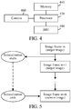
- a front-end program switches a target image to an (i+1) th anchor image.
- the front-end program performs camera pose tracking based on the (i+1) th anchor image in parallel to obtain a first pose parameter.
- the first pose parameter and the second pose parameter are used to correct a positioning result of a current image in a case that a relocalization result (a second pose parameter) is obtained during processing of the current image by the front-end program, thereby resolving a problem that the back-end program cannot control the time of obtaining a successful relocalization result, and a relocalization result obtained several frames of image before cannot be directly used for relocalization of the current image.
- Even if it takes a relatively long time for the back-end program to obtain a relocalization result two pose change amounts can be added to correct the positioning result of the current image, thereby ensuring a relatively adequate relocalization effect.
- AR is a technology that as a camera acquires an image, a camera pose parameter of the camera in the real world (or referred to as the three-dimensional world or the actual world) is calculated in real time, and a virtual element is added according to the camera pose parameter to the image acquired by the camera.
- the virtual element includes, but is not limited to, an image, a video, and a three-dimensional model.
- the objective of the AR technology is to overlay the virtual world on a screen onto the real world to perform interaction.
- the camera pose parameter includes a rotation matrix and a displacement vector.
- the rotation matrix is used to represent a rotation angle of the camera in the real world.
- the displacement vector is used to represent a displacement distance of the camera in the real world.
- a device adds a figure of a virtual human to an image photographed by a camera.
- the image photographed by the camera changes, and a photographing position of the virtual human also changes, thereby simulating an effect that the virtual human is still in the image and the camera photographs the image and the virtual human while the position and pose are changing, so as to present a realistic three-dimensional picture to a user.
- An anchor-switching AR system is an AR system that determines a camera pose parameter in a natural scene based on camera pose tracking of a plurality of consecutive anchor images and overlays the virtual world according to the camera pose parameter onto an image acquired by a camera.
- An inertial measurement unit is an apparatus configured to measure tri-axial attitude angles (or angular velocities) and accelerations of an object.
- the IMU includes three uniaxial accelerometers and three uniaxial gyroscopes.
- the accelerometer is configured to detect an acceleration signal of an object on each coordinate axis of a three-dimensional coordinate system, to calculate the displacement vector (errors may accumulate as time elapses).
- the gyroscopes are configured to detect a rotation matrix of the object in the three-dimensional coordinate system.
- the IMU includes a gyroscope, an accelerometer, and a geomagnetic sensor.
- a manner of establishing a three-dimensional coordinate system is as follows: 1.
- the X axis is defined by a vector product Y ⁇ Z, and a direction tangential to the ground at a current position of the device on the X axis points to the east. 2.
- a direction tangential to the ground at the current position of the device on the Y axis points to the north pole of the geomagnetic field.
- the Z axis points to the sky and is perpendicular to the ground.
- the processor 420 includes one or more processing cores, for example, a 4-core processor, an 8-core processor, and the like.
- the processor 420 is configured to execute at least one of an instruction, a code, a code segment, and a program stored in the memory 440.
- Normal tracking process ( FIG. 7 ): In a camera pose tracking process based on an i th anchor image, it is set that the i th anchor image has a pose change amount including R _i_old and T _i_old relative to the first anchor image.
- the back-end program performs relocalization on the target image relative to the first anchor image, to obtain the second pose parameter.
- the foregoing step 605 includes the following sub-steps:
- Step 605b Perform feature point tracking on the target image relative to the first anchor image, to obtain a target feature point matching the initial feature point.
- each matching feature point pair includes one initial feature point and one target feature point that match each other.
- a tracking algorithm based on visual odometry may be used for feature point tracking. This is not limited in this application.
- a Kanade-Lucas (KLT) optical flow tracking algorithm is used for feature point tracking.
- a SIFT feature descriptor extracted based on a scale-invariant feature transform (SIFT) algorithm and an ORB feature descriptor extracted based on an oriented FAST and rotated BRIEF (ORB, fast feature point extraction and description) algorithm are used to perform feature point tracking.
- SIFT scale-invariant feature transform
- ORB fast feature point extraction and description
- a specific algorithm for feature point tracking is not limited, and a feature point method or a direct method may be used for a feature point tracking process.
- the device calculates a homography matrix between two frames of image according to the initial feature point and the target feature point; and decomposes the homography matrix to obtain a pose change amount including R relocalize and T relocalize of the change of the camera from the initial pose parameter to the target pose parameter.
- relocalization is performed on a target image relative to the first anchor image.
- relocalization may fail in some scenarios. For example, in a case that a photographing pose corresponding to the target image is greatly different from a photographing pose of the first anchor image, relocalization implemented by directly establishing a match between the target image and the first anchor image may fail.
- the picture (1) in FIG. 10 is the first anchor image
- the picture (2) in FIG. 10 is the target image. Because there is an excessively small overlapping area between the target image and the first anchor image, and a sufficient matching degree is not reached, relocalization directly performed on the target image and the first anchor image fails.
- the picture (3) in FIG. 10 is introduced as a first-order keyframe, and relocalization is performed on the target image relative to a first-order keyframe, so that the success probability of relocalization can be improved.
- the back-end program chooses a target keyframe from the keyframe database.
- the target keyframe is an image at the smallest image distance from the target image in the keyframe database.
- the image distance can be represented by any form of an image similarity, an image feature similarity, and a distance between matching feature points. This is not limited in this embodiment of this application.
- the device chooses a target keyframe from the keyframe database by using a similarity between the first global descriptor of the keyframe and the second global descriptor of the target image.
- the device chooses a target keyframe from the keyframe database by using the similarity between the first pose parameter of the keyframe and the reference pose parameter of the target image.
- Step 6052 Perform relocalization on the target image relative to the target keyframe, to obtain a second relocalization result.
- a process of relocalization includes the following steps:
- the device calculates a homography matrix between two frames of image according to the keyframe feature point and the target feature point; and decomposes the homography matrix to obtain the pose change amount including R cm and T cm of the change of the camera from the keyframe pose parameter to the second pose parameter, and use the pose change amount including R cm and T cm as the second relocalization result.
- Step 6053 Calculate a second pose parameter of the camera during acquisition of the target image according to the first relocalization result and the second relocalization result.
- the keyframe database includes: a first-order keyframe with successful first-order relocalization relative to the first anchor image, and/or, and an nth-order keyframe with successful nth order relocalization relative to the (n-1) th -order keyframe in the keyframe database, n being an integer greater than 1.
- a projected feature point obtained after the front-end program maps an initial feature point in the first anchor image onto the target image, and a process of calculating a scale corresponding to the target image according to an average depth of the projected feature point is as follows:
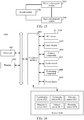
- a result module is provided between the front-end program and the back-end program between.
- the result module is a storage space shared by the front-end program and the back-end program.
- the result module includes a relocalization list, a result-flag, and a result storage location.
- the result module further includes an expand-map list, an abandon time.
- the relocalization list is used to store a target image that requires relocalization.
- the target image is written into the relocalization list.
- the result storage location is used to store the second pose parameter including R relocalize and T relocalice in a case that relocalization succeeds.
- the expand-map list is used to store a candidate image of a keyframe database.
- the front-end program imports an image into the expand-map list during a normal camera tracking process for the back-end program to expand the keyframe database.
- the abandon time is used to store the time at which the front-end program switches an anchor image the last time. For example, in a case that the front-end program sets the target image as the (i+1) th anchor image, the front-end program records the switching time of the (i+1) th anchor image to the abandon time.
- the back-end program monitors the relocalization list and the expand-map list in the result module.
- Step 1201 Determine whether the relocalization list is empty.
- step 1202 it is determined that the front-end program does not have a target image that requires relocalization, and step 1202 is performed.
- step 1204 it is determined that the front-end program has a target image that requires relocalization, and step 1204 is performed.
- Step 1202 Determine whether the expand-map list is empty.
- Step 1203 is performed in a case that the expand-map list is not empty.
- Step 1200 is performed again in a case that the expand-map list is empty.
- Step 1203 Expand a keyframe database.
- the back-end program uses the candidate image in the expand-map list to expand keyframes in the keyframe database, so that keyframes in the keyframe database are added or updated.
- Step 1204 Set the result-flag to still-running.
- Step 1205 Perform relocalization on a target image that requires relocalization.
- Step 1206 Determine whether the relocalization process succeeds.
- Step 1207 is performed in a case that relocalization succeeds.
- Step 1208 is performed in a case that relocalization fails.
- the back-end program sets the result-flag to fail.
- Step 1209 Set the result-flag to success.
- Step 1301 Determine whether there is a tracking result.
- the front-end program obtains a target image acquired after the i th anchor image and after feature point tracking is performed on a target image relative to the i th anchor image, and determines whether there is a tracking result.
- Step 1302 is performed in a case that there is a tracking result.
- Step 1303 is performed in a case that there is no tracking result.
- Step 1302 Set flag1 to false.
- the camera pose tracking process in step 1300 continues to be performed.
- Step 1303 Set flag1 to true.
- the front-end program sets flagl to true, representing that relocalization needs to be performed on the target image.
- Step 1304 Detect the status of flag1.
- the front-end program During processing of each frame of image, the front-end program further detects the status of flag1.
- Step 1305 is performed in a case that the status of flag1 is false.
- the front-end program transmits the target image to the expand-map list for use by the back-end program to expand the keyframe database.
- Step 1306 is performed in a case that the status of flag1 is true.
- the front-end program considers that the target image being processed requires relocalization and detects the state of flag2.
- Step 1307 is performed in a case that the status of flag2 is false, representing that the last relocalization succeeds.
- Step 1313 is performed in a case that the status of flag2 is true, representing that the last relocalization fails.
- the front-end program reads the result-flag in the result module.
- the result-flag is ready, it indicates that the back-end program is in an idle state, and relocalization may be performed on the target image.
- Step 1308 Switch to an (i+1) th anchor image, transmit the abandon time, and transmit the target image to the relocalization list.
- the front-end program switches the target image to the (i+1) th anchor image, and writes the switching time into the abandon time in the result module.
- the front-end program reads the result-flag in the result module.
- Step 1310 is performed in a case that the result-flag is still-running.
- Step 1311 is performed in a case that the result-flag is have-result_ok.
- Step 1312 is performed in a case that the result-flag is have-result_fails.
- Step 1310 Conduct another transaction.
- the front-end program may perform a feature point tracking process on a current image after a target image in a calculation process in which the back-end program performs relocalization on the target image.
- Step 1311 Set flag 1 to fail.
- flagl is set to fail in a case that relocalization of the target image succeeds, representing that relocalization is not required, and a camera tracking process based on the (i+1) th anchor image is performed.
- flag2 is set to success in a case that relocalization of the target image fails.
- Step 1313 Switch to an (i+2) th anchor image, and transmit the abandon time.
- the front-end program obtains a current image after a target image
- flag1 is true and flag2 is true
- a relocalization process of the target image fails.
- the front-end program needs to transmit the current image after the target image to the relocalization list, so that the back-end program initiates a relocalization process on the current image.
- the front-end program switches the current image to an (i+2) th anchor image, and write the switching time into the abandon time in the result module again.
- the back-end program uses the candidate image in the expand-map list to expand a keyframe in a keyframe database, including the following steps: Step 1: Obtain a latest candidate image with successful relocalization.
- the keyframe database may be empty, and the back-end program only uses the first anchor image as an anchor image for relocalization.
- the back-end program only uses the first anchor image as an anchor image for relocalization.
- the back-end program uses the image with successful relocalization as a candidate image that may be added to the keyframe database.
- the successful relocalization includes: successful relocalization relative to the first anchor image, or, successful relocalization relative to an existing keyframe in the keyframe database.
- Step 2 Determine whether the candidate image satisfies an addition condition, the addition condition including: a first distance between the candidate image and the first anchor image is greater than a first threshold, and/or, a second distance between the candidate image and a keyframe added last time is greater than a second threshold.
- the back-end program calculates the first distance between the candidate image and the first anchor image.
- the first distance is used to represent an image similarity or a camera pose similarity between the candidate image and the first anchor image.
- a specific calculation manner of the first distance is not limited.
- for an initial feature point in the first anchor image a target feature point matching the initial feature point exists in the candidate image.
- One initial feature point and a corresponding target feature point constitute a matching feature point pair.
- An L2 distance (a Euclidean distance corresponding to the norm of L2) is calculated according to each matching feature point pair.
- An average value of all L2 distances is used as the first distance between the candidate image and the first anchor image.
- the first threshold is 50 pixels. In a case that the first distance between the candidate image and the first anchor image is greater than 50 pixels, the candidate image is added to the keyframe database.
- the back-end program calculates the second distance between the candidate image and the keyframe added last time.
- the second distance is used to represent an image similarity or a camera pose similarity between the candidate image and the keyframe added last time.
- a specific calculation manner of the second distance is not limited.
- a quantity of relocalization images between the candidate image and the keyframe added last time is used as the second distance.
- the second threshold is 10. In a case that the quantity of relocalization images between the candidate image and the keyframe added last time exceeds 10, the candidate image is added to the keyframe database.
- Step 3 Add the candidate image to the keyframe database in a case that the candidate image satisfies the addition condition.
- the candidate image is added to the keyframe database as a keyframe.
- a first global descriptor of the keyframe, a keyframe feature point, a positioning result of the first relocalization are stored in the keyframe database.
- the first global descriptor is used to represent the image of the keyframe feature by using a small data amount, and the positioning result of the first relocalization may be represented by a keyframe pose parameter of the camera during acquisition of a keyframe or may be represented by the pose change amount of the change of the camera from the initial pose parameter to the keyframe pose parameter.
- Step 4 Skip adding the candidate image to the keyframe database in a case that the candidate image does not satisfy the addition condition.
- the candidate image is not added to the keyframe database in a case that the first distance between the candidate image and the first anchor image is less than the first threshold, or, the second distance between the candidate image and the keyframe added last time is less than the second threshold.
- the keyframe satisfying the foregoing addition condition may be used to expand the keyframe database, but too many keyframes cause calculation amount load to a relocalization process, making it difficult to find a desired image, and therefore are not recommended in the keyframe database.
- a similarity between the candidate image and an existing keyframe is calculated in a case that the candidate image satisfies the addition condition and a quantity of keyframes in the keyframe database reaches a maximum value (for example, 1000).
- a maximum value for example, 1000.
- the foregoing relocalization method in a camera pose tracking process may be used in an AR program.
- a pose of a camera on an electronic device can be tracked in real time according to scene information in the real world, and a display position of an AR element in an AR application is adjusted and changed according to a tracking result.
- An AR program run on the mobile phone in FIG. 1 or FIG. 2 is used as an example.
- a still cartoon character standing on a book needs to be displayed, no matter how a user moves the mobile phone, it is only necessary to change a display position of the cartoon character according to a pose change of a camera on the mobile phone, so that the standing position of the cartoon character on the book can be kept unchanged.
- FIG. 15 is a block diagram of a relocalization apparatus in a camera pose tracking process according to an exemplary embodiment of this application.
- the relocalization apparatus may be implemented by software, hardware or a combination of software and hardware as an entire electronic device (or referred to as a mobile electronic device) or a part of the electronic device.
- the relocalization apparatus includes a front-end program module 1520 and a back-end program module 1540.
- the front-end program module 1520 is configured to sequentially perform a camera pose tracking process on a plurality of anchor images.
- the front-end program module 1520 is further configured to obtain a target image acquired after an i th anchor image in the plurality of anchor images, i being a positive integer.
- the front-end program module 1520 is further configured to: switch the target image to an (i+1) th anchor image in a case that the target image satisfies a relocalization condition, and transmit the target image to the back-end program module.
- the front-end program module 1520 is further configured to: obtain a current image acquired after the target image, and perform feature point tracking on the current image relative to the target image to obtain a first pose parameter, the first pose parameter being used to represent a change amount of a camera pose from the target image to the current image.
- the front-end program module 1520 is configured to calculate a current pose parameter of the current image according to the first pose parameter and the second pose parameter.
- the back-end program module 1540 is configured to perform relocalization on the target image relative to the first anchor image, to obtain the second pose parameter; and/or, the back-end program module 1540 is configured to perform relocalization on the target image relative to a keyframe in a keyframe database, to obtain the second pose parameter, the keyframe being an image the has successful relocalization and has a relocalization result relative to the first anchor image.
- the front-end program module 1520 is configured to calculate a current pose parameter of the current image according to the first pose parameter and the second pose parameter, including:
- the front-end program module 1520 is configured to map an initial feature point in the first anchor image onto the target image to obtain a projected feature point, and calculate a scale corresponding to the target image according to an average depth of the projected feature point.
- the apparatus further includes a result module 1560, the result module 1560 being a storage space shared by the front-end program module and the back-end program module, where the front-end program module 1520 is configured to write the target image into a relocalization image list in the result module 1560; and the back-end program module 1540 is configured to read the target image from the relocalization image list.
- the front-end program module 1520 configured to detect whether a result status bit in the result module 1560 is a ready state; the front-end program module 1520 is configured to write the target image into the relocalization image list in the result module 1560 in a case that a detection result is that the result status bit is the ready state.
- the back-end program module 1540 is configured to write the second pose parameter into a result storage location in the result module, the result module 1560 being a storage space shared by the front-end program module 1520 and the back-end program module 1540; and the front-end program module 1520 is configured to read the second pose parameter from the result storage location.
- the front-end program module 1520 is configured to write the target image into an expand-map list in the result module; and the back-end program module 1540 is configured to: read the target image from the expand-map list in a case that the target image has successful relocalization and satisfies a preset condition, and add the target image to the keyframe database.
- the relocalization apparatus in a camera pose tracking process provided in the foregoing embodiments implements relocalization
- only divisions of the foregoing functional modules are described by using an example.
- the foregoing functions may be allocated to and completed by different functional modules according to requirements, that is, the internal structure of the device is divided into different functional modules, to complete all or some of the foregoing described functions.
- the relocalization apparatus provided in the foregoing embodiments belongs to the same concept as the embodiments of the relocalization method. For a specific implementation process of the relocalization apparatus, refer to the method embodiments for details. Details are not described herein again.
- FIG. 16 is a structural block diagram of an electronic device 1600 according to an exemplary embodiment of this application.
- the electronic device 1600 may be a smart phone, a tablet computer, a Moving Picture Experts Group Audio Layer III (MP3) player, a Moving Picture Experts Group Audio Layer IV (MP4) player, a laptop computer or a desktop computer.
- MP3 Moving Picture Experts Group Audio Layer III
- MP4 Moving Picture Experts Group Audio Layer IV
- the electronic device 1600 may also be referred to as a user device, a portable electronic device, a laptop electronic device, and a desktop electronic device, among other names.
- the electronic device 1600 includes a processor 1601 and a memory 1602.
- the processor 1601 may include one or more processing cores, for example, a 4-core processor, an 8-core processor, and the like.
- the processor 1601 may be implemented in at least one hardware form of a digital signal processor (DSP), a field-programmable gate array (FPGA), and a programmable logic array (PLA).
- the processor 1601 may also include a main processor and a co-processor.
- the main processor is a processor configured to process data in a wake-up state or is referred to as a central processing unit (CPU).
- the co-processor is a low power consumption processor configured to process data in a standby state.
- the processor 1601 may be integrated with a graphics processing unit (GPU).
- the GPU is configured to render and draw content that needs to be displayed on a display.
- the processor 1601 may further include an artificial intelligence (AI) processor.
- the AI processor is configured to process a computing operation related to machine learning.
- the memory 1602 may include one or more computer-readable storage media.
- the computer-readable storage medium may be non-transient.
- the memory 1602 may further include a high-speed random access memory (RAM) and a non-volatile memory such as one or more magnetic disk storage devices or flash memory storage devices.
- the non-transient computer-readable storage medium in the memory 1602 is configured to store at least one instruction.
- the at least one instruction is executed by the processor 1601 to implement the relocalization method in a camera pose tracking process provided in the method embodiments of this application.
- the electronic device 1600 further optionally includes a peripheral interface 1603 and at least one peripheral.
- the processor 1601, the memory 1602, and the peripheral interface 1603 may be connected by a bus or a signal line.
- Peripherals may be connected to the peripheral interface 1603 by a bus, a signal line or a circuit board.
- the peripheral includes at least one of a radio frequency (RF) circuit 1604, a touch display 1605, a camera component 1606, an audio circuit 1607, a positioning component 1608, and a power supply 1609.
- RF radio frequency
- the peripheral interface 1603 may be configured to connect at least one peripheral related to an input/output (I/O) to the processor 1601 and the memory 1602.
- the processor 1601, the memory 1602, and the peripheral interface 1603 are integrated in one same chip or circuit board.
- any one or two of the processor 1601, the memory 1602, and the peripheral interface 1603 may be separately implemented on a chip or circuit board. This is not limited in this embodiment.
- the RF circuit 1604 is configured to receive and transmit an RF signal, which is also referred to as electromagnetic signal.
- the RF circuit 1604 communicates with a communications network and another communication device by using an electromagnetic signal.
- the RF circuit 1604 converts an electrical signal into an electromagnetic signal for transmission, or, converts a received electromagnetic signal into an electrical signal.
- the RF circuit 1604 includes an antenna system, an RF transceiver, one or more amplifiers, a tuner, an oscillator, a DSP, a CODEC chip set, a subscriber identity module card, and the like.
- the RF circuit 1604 may communicate with another electronic device by using at least one wireless communication protocol.
- the wireless communication protocol includes, but is not limited to, a World Wide Web, a metropolitan area network, an intranet, various generations of mobile communications networks (2G, 3G, 4G, and 5G), a wireless local area network and/or a Wireless Fidelity (Wi-Fi) network.
- the RF circuit 1604 may further include a Near Field Communication (NFC)-related circuit. This is not limited in this application.
- NFC Near Field Communication
Landscapes
- Engineering & Computer Science (AREA)
- Computer Vision & Pattern Recognition (AREA)
- Physics & Mathematics (AREA)
- General Physics & Mathematics (AREA)
- Theoretical Computer Science (AREA)
- Multimedia (AREA)
- Studio Devices (AREA)
- Image Analysis (AREA)
Applications Claiming Priority (2)
| Application Number | Priority Date | Filing Date | Title |
|---|---|---|---|
| CN201810392872.5A CN108876854B (zh) | 2018-04-27 | 2018-04-27 | 相机姿态追踪过程的重定位方法、装置、设备及存储介质 |
| PCT/CN2019/079781 WO2019205868A1 (zh) | 2018-04-27 | 2019-03-27 | 相机姿态追踪过程的重定位方法、装置、设备及存储介质 |
Publications (3)
| Publication Number | Publication Date |
|---|---|
| EP3786895A1 true EP3786895A1 (de) | 2021-03-03 |
| EP3786895A4 EP3786895A4 (de) | 2022-01-19 |
| EP3786895B1 EP3786895B1 (de) | 2025-12-10 |
Family
ID=64326671
Family Applications (1)
| Application Number | Title | Priority Date | Filing Date |
|---|---|---|---|
| EP19794077.8A Active EP3786895B1 (de) | 2018-04-27 | 2019-03-27 | Verfahren, vorrichtung und einrichtung zur neupositionierung in einem kameraausrichtungsverfolgungsverfahren und speichermedium |
Country Status (4)
| Country | Link |
|---|---|
| US (1) | US11276183B2 (de) |
| EP (1) | EP3786895B1 (de) |
| CN (1) | CN108876854B (de) |
| WO (1) | WO2019205868A1 (de) |
Cited By (1)
| Publication number | Priority date | Publication date | Assignee | Title |
|---|---|---|---|---|
| WO2025228736A1 (de) * | 2024-04-29 | 2025-11-06 | Robert Bosch Gmbh | Verfahren zum korrigieren einer pose eines mobilen geräts |
Families Citing this family (19)
| Publication number | Priority date | Publication date | Assignee | Title |
|---|---|---|---|---|
| CN108876854B (zh) | 2018-04-27 | 2022-03-08 | 腾讯科技(深圳)有限公司 | 相机姿态追踪过程的重定位方法、装置、设备及存储介质 |
| CN110544280B (zh) | 2018-05-22 | 2021-10-08 | 腾讯科技(深圳)有限公司 | Ar系统及方法 |
| CN110008856B (zh) * | 2019-03-20 | 2021-08-17 | 联想(北京)有限公司 | 定位方法和电子设备 |
| JP7222120B2 (ja) * | 2019-05-03 | 2023-02-14 | トヨタ モーター ヨーロッパ | 対象探索用画像取得手段 |
| US11145083B2 (en) * | 2019-05-21 | 2021-10-12 | Microsoft Technology Licensing, Llc | Image-based localization |
| CN110307838B (zh) * | 2019-08-26 | 2019-12-10 | 深圳市优必选科技股份有限公司 | 机器人重定位方法、装置、计算机可读存储介质及机器人 |
| JP7404011B2 (ja) * | 2019-09-24 | 2023-12-25 | 東芝テック株式会社 | 情報処理装置 |
| US11315326B2 (en) * | 2019-10-15 | 2022-04-26 | At&T Intellectual Property I, L.P. | Extended reality anchor caching based on viewport prediction |
| CN111339228B (zh) * | 2020-02-18 | 2023-08-11 | Oppo广东移动通信有限公司 | 一种地图更新方法、设备、云服务器和存储介质 |
| CN111552757B (zh) * | 2020-04-30 | 2022-04-01 | 上海商汤临港智能科技有限公司 | 生成电子地图的方法、装置、设备及存储介质 |
| CN112164114B (zh) * | 2020-09-23 | 2022-05-20 | 天津大学 | 一种基于天际线匹配的室外主动相机重定位方法 |
| CN113358665A (zh) * | 2021-05-25 | 2021-09-07 | 同济大学 | 一种无人机隧洞缺陷检测方法及系统 |
| CN115760584B (zh) * | 2021-09-03 | 2026-03-24 | 华为技术有限公司 | 一种图像处理方法及相关设备 |
| CN113792639B (zh) * | 2021-09-07 | 2025-04-18 | 北京沃东天骏信息技术有限公司 | 视频关键帧提取方法、电子设备及存储介质 |
| CN114022560A (zh) * | 2021-10-14 | 2022-02-08 | 浙江商汤科技开发有限公司 | 标定方法及相关装置、设备 |
| CN114415839B (zh) * | 2022-01-27 | 2025-12-02 | 歌尔科技有限公司 | 一种信息显示方法、装置、设备及存储介质 |
| CN116193099A (zh) * | 2023-02-21 | 2023-05-30 | 联想(北京)有限公司 | 一种裸眼3d显示控制方法、装置及电子设备 |
| CN117033769B (zh) * | 2023-07-07 | 2026-01-13 | 中国平安人寿保险股份有限公司 | 一种前端组件检索方法、装置、设备及存储介质 |
| US20250027773A1 (en) * | 2023-07-18 | 2025-01-23 | Qualcomm Incorporated | Inertial navigation aided with multi-interval pose measurements |
Family Cites Families (17)
| Publication number | Priority date | Publication date | Assignee | Title |
|---|---|---|---|---|
| US6787750B1 (en) * | 2000-06-29 | 2004-09-07 | Siemens Corporate Research, Inc. | Method and apparatus for robust optical tracking with beacon markers |
| CN104243833B (zh) * | 2014-09-30 | 2017-12-08 | 精宸智云(武汉)科技有限公司 | 一种相机姿态的调整方法及装置 |
| US10802147B2 (en) * | 2016-05-18 | 2020-10-13 | Google Llc | System and method for concurrent odometry and mapping |
| US20170374256A1 (en) * | 2016-06-24 | 2017-12-28 | Qualcomm Incorporated | Method and apparatus for rolling shutter compensation |
| CN106595601B (zh) * | 2016-12-12 | 2020-01-07 | 天津大学 | 一种无需手眼标定的相机六自由度位姿精确重定位方法 |
| CN106708048B (zh) * | 2016-12-22 | 2023-11-28 | 清华大学 | 机器人的天花板图像定位方法和系统 |
| CN106885574B (zh) * | 2017-02-15 | 2020-02-07 | 北京大学深圳研究生院 | 一种基于重跟踪策略的单目视觉机器人同步定位与地图构建方法 |
| CN107300917B (zh) * | 2017-05-23 | 2019-07-09 | 北京理工大学 | 一种基于分层架构的视觉slam后端优化方法 |
| CN107633536B (zh) * | 2017-08-09 | 2020-04-17 | 武汉科技大学 | 一种基于二维平面模板的相机标定方法及系统 |
| CN109542093B (zh) * | 2017-09-22 | 2022-06-07 | 华为技术有限公司 | 一种处理数据的方法和装置 |
| CN110555883B (zh) | 2018-04-27 | 2022-07-22 | 腾讯科技(深圳)有限公司 | 相机姿态追踪过程的重定位方法、装置及存储介质 |
| CN108876854B (zh) * | 2018-04-27 | 2022-03-08 | 腾讯科技(深圳)有限公司 | 相机姿态追踪过程的重定位方法、装置、设备及存储介质 |
| CN110599549B (zh) | 2018-04-27 | 2023-01-10 | 腾讯科技(深圳)有限公司 | 界面显示方法、装置及存储介质 |
| CN108596976B (zh) | 2018-04-27 | 2022-02-22 | 腾讯科技(深圳)有限公司 | 相机姿态追踪过程的重定位方法、装置、设备及存储介质 |
| CN108615248B (zh) | 2018-04-27 | 2022-04-05 | 腾讯科技(深圳)有限公司 | 相机姿态追踪过程的重定位方法、装置、设备及存储介质 |
| CN108537845B (zh) | 2018-04-27 | 2023-01-03 | 腾讯科技(深圳)有限公司 | 位姿确定方法、装置及存储介质 |
| CN108682038B (zh) | 2018-04-27 | 2021-12-14 | 腾讯科技(深圳)有限公司 | 位姿确定方法、装置及存储介质 |
-
2018
- 2018-04-27 CN CN201810392872.5A patent/CN108876854B/zh active Active
-
2019
- 2019-03-27 WO PCT/CN2019/079781 patent/WO2019205868A1/zh not_active Ceased
- 2019-03-27 EP EP19794077.8A patent/EP3786895B1/de active Active
-
2020
- 2020-07-01 US US16/919,059 patent/US11276183B2/en active Active
Cited By (1)
| Publication number | Priority date | Publication date | Assignee | Title |
|---|---|---|---|---|
| WO2025228736A1 (de) * | 2024-04-29 | 2025-11-06 | Robert Bosch Gmbh | Verfahren zum korrigieren einer pose eines mobilen geräts |
Also Published As
| Publication number | Publication date |
|---|---|
| US20200334836A1 (en) | 2020-10-22 |
| US11276183B2 (en) | 2022-03-15 |
| CN108876854A (zh) | 2018-11-23 |
| EP3786895B1 (de) | 2025-12-10 |
| WO2019205868A1 (zh) | 2019-10-31 |
| EP3786895A4 (de) | 2022-01-19 |
| CN108876854B (zh) | 2022-03-08 |
Similar Documents
| Publication | Publication Date | Title |
|---|---|---|
| US11276183B2 (en) | Relocalization method and apparatus in camera pose tracking process, device, and storage medium | |
| US11205282B2 (en) | Relocalization method and apparatus in camera pose tracking process and storage medium | |
| US11189037B2 (en) | Repositioning method and apparatus in camera pose tracking process, device, and storage medium | |
| US11481923B2 (en) | Relocalization method and apparatus in camera pose tracking process, device, and storage medium | |
| US11798190B2 (en) | Position and pose determining method, apparatus, smart device, and storage medium | |
| CN110148178B (zh) | 相机定位方法、装置、终端及存储介质 | |
| CN111897429B (zh) | 图像显示方法、装置、计算机设备及存储介质 | |
| WO2019154231A1 (zh) | 图像处理方法、电子设备及存储介质 | |
| WO2022042425A1 (zh) | 视频数据处理方法、装置、计算机设备及存储介质 | |
| CN110986930A (zh) | 设备定位方法、装置、电子设备及存储介质 | |
| CN108682037B (zh) | 相机姿态追踪过程的重定位方法、装置、设备及存储介质 | |
| CN110570465B (zh) | 实时定位与地图构建方法、装置及计算机可读存储介质 | |
| CN110633336B (zh) | 激光数据搜索范围的确定方法、装置及存储介质 | |
| KR102084161B1 (ko) | 이미지를 보정하는 전자 장치 및 그 제어 방법 | |
| CN113409235B (zh) | 一种灭点估计的方法及装置 | |
| WO2019233299A1 (zh) | 地图构建方法、装置及计算机可读存储介质 | |
| CN112669291B (zh) | 图片处理方法、装置、设备及计算机可读存储介质 | |
| CN111354032B (zh) | 一种生成视差图的方法及装置 | |
| CN116502382A (zh) | 传感器数据的处理方法、装置、设备及存储介质 | |
| CN115457047A (zh) | 天空分割方法、装置、计算机设备及存储介质 |
Legal Events
| Date | Code | Title | Description |
|---|---|---|---|
| STAA | Information on the status of an ep patent application or granted ep patent |
Free format text: STATUS: THE INTERNATIONAL PUBLICATION HAS BEEN MADE |
|
| PUAI | Public reference made under article 153(3) epc to a published international application that has entered the european phase |
Free format text: ORIGINAL CODE: 0009012 |
|
| STAA | Information on the status of an ep patent application or granted ep patent |
Free format text: STATUS: REQUEST FOR EXAMINATION WAS MADE |
|
| 17P | Request for examination filed |
Effective date: 20200929 |
|
| AK | Designated contracting states |
Kind code of ref document: A1 Designated state(s): AL AT BE BG CH CY CZ DE DK EE ES FI FR GB GR HR HU IE IS IT LI LT LU LV MC MK MT NL NO PL PT RO RS SE SI SK SM TR |
|
| AX | Request for extension of the european patent |
Extension state: BA ME |
|
| DAV | Request for validation of the european patent (deleted) | ||
| DAX | Request for extension of the european patent (deleted) | ||
| A4 | Supplementary search report drawn up and despatched |
Effective date: 20211217 |
|
| RIC1 | Information provided on ipc code assigned before grant |
Ipc: G06T 7/269 20170101ALI20211213BHEP Ipc: G06T 7/73 20170101AFI20211213BHEP |
|
| RAP3 | Party data changed (applicant data changed or rights of an application transferred) |
Owner name: TENCENT TECHNOLOGY (SHENZHEN) COMPANY LIMITED |
|
| GRAP | Despatch of communication of intention to grant a patent |
Free format text: ORIGINAL CODE: EPIDOSNIGR1 |
|
| STAA | Information on the status of an ep patent application or granted ep patent |
Free format text: STATUS: GRANT OF PATENT IS INTENDED |
|
| INTG | Intention to grant announced |
Effective date: 20250225 |
|
| GRAJ | Information related to disapproval of communication of intention to grant by the applicant or resumption of examination proceedings by the epo deleted |
Free format text: ORIGINAL CODE: EPIDOSDIGR1 |
|
| STAA | Information on the status of an ep patent application or granted ep patent |
Free format text: STATUS: REQUEST FOR EXAMINATION WAS MADE |
|
| GRAP | Despatch of communication of intention to grant a patent |
Free format text: ORIGINAL CODE: EPIDOSNIGR1 |
|
| STAA | Information on the status of an ep patent application or granted ep patent |
Free format text: STATUS: GRANT OF PATENT IS INTENDED |
|
| INTC | Intention to grant announced (deleted) | ||
| INTG | Intention to grant announced |
Effective date: 20250703 |
|
| GRAS | Grant fee paid |
Free format text: ORIGINAL CODE: EPIDOSNIGR3 |
|
| GRAA | (expected) grant |
Free format text: ORIGINAL CODE: 0009210 |
|
| STAA | Information on the status of an ep patent application or granted ep patent |
Free format text: STATUS: THE PATENT HAS BEEN GRANTED |
|
| AK | Designated contracting states |
Kind code of ref document: B1 Designated state(s): AL AT BE BG CH CY CZ DE DK EE ES FI FR GB GR HR HU IE IS IT LI LT LU LV MC MK MT NL NO PL PT RO RS SE SI SK SM TR |
|
| REG | Reference to a national code |
Ref country code: CH Ref legal event code: F10 Free format text: ST27 STATUS EVENT CODE: U-0-0-F10-F00 (AS PROVIDED BY THE NATIONAL OFFICE) Effective date: 20251210 Ref country code: GB Ref legal event code: FG4D |
|
| REG | Reference to a national code |
Ref country code: DE Ref legal event code: R096 Ref document number: 602019079085 Country of ref document: DE |
|
| REG | Reference to a national code |
Ref country code: IE Ref legal event code: FG4D |
|
| PGFP | Annual fee paid to national office [announced via postgrant information from national office to epo] |
Ref country code: GB Payment date: 20260324 Year of fee payment: 8 |
|
| PG25 | Lapsed in a contracting state [announced via postgrant information from national office to epo] |
Ref country code: ES Free format text: LAPSE BECAUSE OF FAILURE TO SUBMIT A TRANSLATION OF THE DESCRIPTION OR TO PAY THE FEE WITHIN THE PRESCRIBED TIME-LIMIT Effective date: 20251210 |
|
| REG | Reference to a national code |
Ref country code: LT Ref legal event code: MG9D |
|
| PG25 | Lapsed in a contracting state [announced via postgrant information from national office to epo] |
Ref country code: NO Free format text: LAPSE BECAUSE OF FAILURE TO SUBMIT A TRANSLATION OF THE DESCRIPTION OR TO PAY THE FEE WITHIN THE PRESCRIBED TIME-LIMIT Effective date: 20260310 |
|
| PGFP | Annual fee paid to national office [announced via postgrant information from national office to epo] |
Ref country code: DE Payment date: 20260320 Year of fee payment: 8 |
|
| PG25 | Lapsed in a contracting state [announced via postgrant information from national office to epo] |
Ref country code: FI Free format text: LAPSE BECAUSE OF FAILURE TO SUBMIT A TRANSLATION OF THE DESCRIPTION OR TO PAY THE FEE WITHIN THE PRESCRIBED TIME-LIMIT Effective date: 20251210 Ref country code: HR Free format text: LAPSE BECAUSE OF FAILURE TO SUBMIT A TRANSLATION OF THE DESCRIPTION OR TO PAY THE FEE WITHIN THE PRESCRIBED TIME-LIMIT Effective date: 20251210 |
|
| REG | Reference to a national code |
Ref country code: NL Ref legal event code: MP Effective date: 20251210 |
|
| PG25 | Lapsed in a contracting state [announced via postgrant information from national office to epo] |
Ref country code: RS Free format text: LAPSE BECAUSE OF FAILURE TO SUBMIT A TRANSLATION OF THE DESCRIPTION OR TO PAY THE FEE WITHIN THE PRESCRIBED TIME-LIMIT Effective date: 20260310 |
|
| PG25 | Lapsed in a contracting state [announced via postgrant information from national office to epo] |
Ref country code: LV Free format text: LAPSE BECAUSE OF FAILURE TO SUBMIT A TRANSLATION OF THE DESCRIPTION OR TO PAY THE FEE WITHIN THE PRESCRIBED TIME-LIMIT Effective date: 20251210 |